static and dynamic load generator based on induction...
TRANSCRIPT

1
Static and Dynamic Load Generator based on Induction Motor
H.Azizi , A.Vahedi and GH.papi Power Engineering Department
Iran University of Science &Technology
Abstract: Implementation of complex test for electrical machines usually demands special experimental equipments. To meet this end, electrical machines test benchs are designed and constructed. In this system different industrial load characteristic are generated for test machine and its drive using a dynamometer . In this paper an induction motor vector controlled load generator based on torque tracking control method, is proposed as load generator. In this method, a direct power control PWM rectifier, guarantee the four-quadrant operation of dynamometer. For investigation of proposed dynamometer performance, different parts of this system are simulated in SIMULINK/MATLAB and the Simulation results are presented. Keywords: Dynamometer, Indirect vector control, direct controlled PWM rectifier, Test bench
1 Introduction Modern industrial variable speed drive systems are a complex combination of an electrical machine ,a power electronic device, and a digital processor system, executing a control algorithm. Such device can be used in applications where open loop control is employed, or alternately they can be used in applications where high precision servo performance is desired. industrial process often contain non-linear mechanical loads drived by electrical drives. It is desirable to be able to test the overall performance of the total drive system combination, under controlled conditions, in the laboratory for desired industrial load profile. For this purpose a electrical machine test faculties have been used. Test bench of electric machines made of three part: dynamometer and its control system, data acquisition system and motor (or drive) under test [1,2,3]. dynamometer are commonly used during the development process of a drive system in order to assess its performance ,in part because it is not always practical to test it directly with the actual load. Hence rotating machinery can be tested on this dynamometer to determine their transient and steady-stead characteristic with a practical load. In Classical dynamometer the load is adjusted by altering the frictional drag or the electrical output of the generator ,or by varying the slip of the clutch .in both case ,the load is passive and the machine under test can only be tested under steady –stat loading
condition. In [1,2] dynamic load generator (dynamometer) implemented using a DC motor and based on reference model control. In this methods, it is necessary to know the accurate model of the under test motor. In [4,5,6] dynamometer control done in closed loop manner. In this way under test motor and drive is a component part of the closed loop control system and required to measurement the motor under test electrical torque. In this method the electric torque of under test motor should be measured, that isn’t desired. In this paper at first, static and dynamic characteristics of mechanical load are studied. In order to produce arbitrary loads profile, it is assumed that torque characteristics of arbitrary load versus speed is known, and The user inputs the desired load characteristic by selecting polynomial and inertia coefficient. Then by measuring speed, the reference torque is produced. For tracking such reference torque, an indirect vector control drive system force the torque of load generator motor on reference value. To achieve four-quadrant operation of the dynamometer, the load generator drive must capable to send the power back to the grid in generator mode. For this purpose, a direct control PWM rectifier topology is used. To study of the proposed method ,a precise model of different parts of such system are simulated in SIMULINK/MATLAB and some typical industrial load, both static and dynamic, generate and imposed on under test motor . Several Simulation results show that the static or dynamic characteristic of industrial linear or nonlinear loads can be modeled, precisely, for motor and drive under test.
Proceedings of the 5th WSEAS Int. Conf. on Power Systems and Electromagnetic Compatibility, Corfu, Greece, August 23-25, 2005 (pp558-563)
2
Drive Load 2 Static and dynamic characteristic of typical load To produce desired load profile, first different component part of the load must be known. Basically, torque characteristics of the load can be divided to two component part which are: static and dynamic component. So according to[7,8,9] we can written as:
(1) sdl TTT += Static component, present load torque in any steady state speed. Static torque characteristics as stated in equation(2) is a function of speed.
(2) ∑
∞
−∞=
=n
nmnl AT ω
In this equation lT is the static torque of the load in mN. , mω is angular speed of the motor in
secrad and nA are constants that are chosen according to the load characteristics manually . For any load the nA constants must be chosen in such way that can describe torque speed characteristics for whole speed range. The dynamic characteristics of the load show the load torque in the accelerating and decelerating duration. Following equation gives dynamic torque for the rotational body.
(3)
dtdJT Lldω
=
Where mω is angular speed and dtd mω is angular acceleration and lJ is the inertia moment of the body. angular acceleration value in accelerating duration is positive and this dynamic torque is added to the load torque. In the deceleration duration, this term is negative and resultant dynamic torque is added to the dynamometer torque and in steady state, this term of load torque is zero. The general equation for torque-speed characteristics of the load is:
(4) ∑∞
−∞=
+=+=n
nmn
mlsldl A
dtdJTTT ωω
As shown in fig.1 if the electric drive rotated a mechanical load , we have:
(5) mmmlm D
dtdJTT ωω
+=−
(6) ∑∞
−∞=
++=n
mmnmn
mll DA
dtdJT ωωω
Where lT and eT are load and motor torque,
lJ and mJ are load and motor inertia moment
and lD and mD are load and motor friction constant respectively. Substituting 5 in 6 results:
(7) ml
nm
nn
mlmm
mmm DA
dtd
JDdt
dJT ω+ω+
ω+ω+
ω= ∑
∞
−∞=
(8)
nm
nn
mTm A
dtdJT ω+ω
= ∑∞
−∞=
Where mlDω and mmD ω can be combined in term
∑+∞
∞−
nmnA ω .
As result, above mentioned equation could be stated as:
(9) nm
nn
mte A
dtdJt ω+ω
= ∑∞
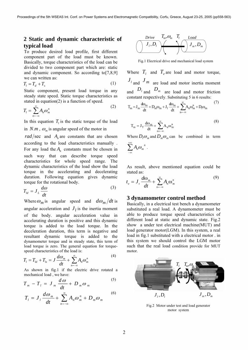
−∞= 3 dynamometer control method Basically, in a electrical test bench a dynamometer substituted a real load. A dynamometer must be able to produce torque speed characteristics of different load at static and dynamic state. Fig.2 show a under test electrical machine(MUT) and load generator motor(LGM). In this system, a real load in fig.1 substituted with a electrical motor . in this system we should control the LGM motor such that the real load condition provide for MUT motor.
mmT ω,lT
mm DJ ,ll DJ ,
Fig.2 Motor under test and load generator motor system
Fig.1 Electrical drive and mechanical load system
ll DJ , mm DJ ,mmT ω, lT
Proceedings of the 5th WSEAS Int. Conf. on Power Systems and Electromagnetic Compatibility, Corfu, Greece, August 23-25, 2005 (pp558-563)

3
Regarding to equation (4) the arbitrary mechanical load can be expressed as:
(10)
memm
em
mmmload
Ddt
dJ
AAAAT
ωω
ωωω
++
++++= ......33
2210
*
Where, nAAA ,...,, 10 are constants, emJ is inertia moment that dynamometer must generate and
mω is a measured angular velocity ( secrad ). The block diagram of an induction motor vector controlled load generator based on torque tracking control method is shown in fig.3. in this system the shaft speed is measured and nAAA ,...,, 10 and
emJ defined by operator. hence we can calculate the reference torque (that dynamometer must model for under test motor), determined from eq.(10). This torque consist of static and dynamic term, that are proportional with angular speed and its derivative respectively. For such system can write:
(11) ( ) mlm
mlmlsm DD
dtd
JJTT ωω
)( +++=−
Where mT is electric torque of the MUT and lST is static torque of the LGM. The actual torque that dynamometer yields to the shaft is:
(12) ml
mllrealload D
dtd
JTT ωω
++=−
Where mlm
l Ddt
dJ ω
ω+ , is dynamic torque
results from the inherent behavior of LGM. If the desired dynamic torque that dynamometer must
produced be memm
em Ddt
dJ ω
ω+ then the actual
reference dynamic torque that dynamometer must produce will be:
(13)
)(
)(
mlm
l
memm
emrealdynamic
Ddt
dJ
Ddt
dJT
ωω
ωω
+
−+=−
So the total reference torque must be:
(14)
)()(
......* 33
2210
mlm
lmemm
em
mmmrealload
Ddt
dJDdt
dJ
AAAAT
ωωωωωωω
+−++
++++=−
Final equation will be as follow:
(15) mm
mmrealloadm D
dtdJTT ωω
+=− −
Where: (16)
)()()(
1lm
lmLmm TT
DDsJJ−
+++=ω
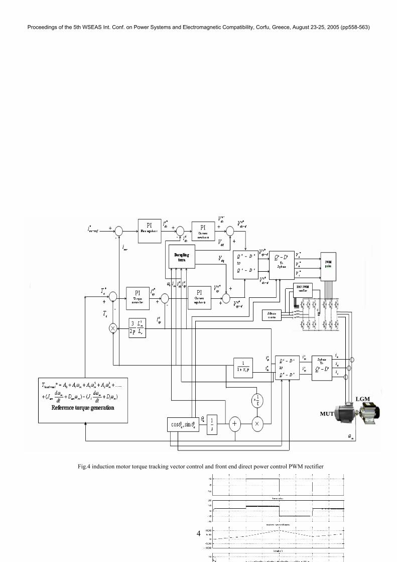
4 Load generator controller structure As explain before, in proposed method, for any arbitrary load characteristics, a reference torque product from eqs. 11 to 16 according to block diagram of fig.3. In this paper a three phase squirrel cage induction motor is used as load generator. To track this reference torque, an indirect vector control strategy using VSI-inverter is implemented. Fig.4 shows the control structure of LGM’s control system. In order to test the MUT motor in any conditions it is important that The LGM motor drive be capable to operate at four-quadrant of the torque speed plan. Because of well known advantage of PWM rectifier, we implement a direct power controlled PWM rectifier as rectifier in front-end of drive system. The DPC/PWM rectifier has many advantages than classical rectifier (diode rectifier), such as: DC link voltage control at different operating condition, power recovery capability, sinusoidal input current and high power factor at AC side. Hence The proposed fast dynamic four-quadrant torque tracking system, provide an appropriate controller for LGM in industrial load generation. 5 Modeling and simulation results To investigate performance of dynamometer Control system shown in fig.3, such system is simulated in SIMULINK/MATLAB and simulation result for several typical load presented in each case. In this study an induction motor with parameters given in index is used. To verify the performance of torque tracking control strategy, the simulation performed for a time varying reference torque. Fig.5 show the reference torque, electrical torque , speed and stator current in this condition. Simulation result shows that the indirect vector control torque tracking strategy have appropriate accuracy and fast dynamic. For investigate the operation of LGM’s control method ,some typical industrial load profile is generate to test a similar squirrel cage induction motor which fed bye a nominal three-phase voltage.
Proceedings of the 5th WSEAS Int. Conf. on Power Systems and Electromagnetic Compatibility, Corfu, Greece, August 23-25, 2005 (pp558-563)
4
MUT
LGM
Fig.4 induction motor torque tracking vector control and front end direct power control PWM rectifier
Proceedings of the 5th WSEAS Int. Conf. on Power Systems and Electromagnetic Compatibility, Corfu, Greece, August 23-25, 2005 (pp558-563)

5
Fig.6 shows simulation result of MUT test under time varying dynamic torque and time varying static constant torque. Simulation result constitute reference load ,LGM’s electrical torque, MUT’s electrical torque, MUT’s speed,LGM’s stator current and MUT’s stator current.LGM’s active power during test priod is shown in fig.7
Fig.8,9 show the Simulation result for Induction motor free run test .in fig .8 the command inertia is less than the of LGM’s moment inertia( lJ ). As shown in fig.8 in this condition the LGM motor operate as motor and product negative breaking dynamic torque during acceleration .as shown in fig.9 for command inertia larg than the of LGM’s moment inertia, the LGM product positive
breaking dynamic torque during acceleration and increase acceleration time.
In another study (not shown) a constant torque load is simulated for two command inertia. When the command inertia is equal to the LGM’s inertia, dynamic torque reference equal to zero. Hence the LGM’s only product steady state torque that equal to 10N.m. But for less command inertia the dynamic torque is negative and adds to steady state torque. this shown that the acceleration is faster than the former case. the simulation result show that for very low dynamic torque command, the PI current controller of LGM will be saturated and practically it is impossible to achieve a very fast acceleration. To over came this problem it is necessary select a load generator motor with low inertia and large nominal value. Conclusion
Fig.6 LGM’s electrical torque, MUT’s electrical torque, MUT’s speed, LGM’s stator current and
MUT’s stator current
Fig.7 LGM’s active power during test period
Fig.8 MUT free run test for dynamic load equal to:
dt
dJT mlload
ω5.0** =
Fig.9 MUT free run test for dynamic load equal to:
dtd
JT mlload
ω10** =
Proceedings of the 5th WSEAS Int. Conf. on Power Systems and Electromagnetic Compatibility, Corfu, Greece, August 23-25, 2005 (pp558-563)

6
In this paper an induction motor vector controlled load generator based on torque tracking control method is used to modeling real industrial mechanical load for electrical machine test bed. This dynamometer utilized indirect vector control strategy and PWM rectifier, thus four-quadrant operation in torque speed plan is feasible. Considering good dynamic of this system, production of high order, linear or nonlinear load profile is possible in steady stead or dynamic condition. After simulation of dynamometer, several programmed load profile implemented. Simulation result for linear and nonlinear load profile in static and dynamic state illustrate that this system can model the arbitrary load profile with good accuracy. Reference [1] Robert Wendel Newton ,Robert E.Betz ,and H.Bruce Penflod”Emulation Dynamic Load Characteristics Using Dynamic Dynamomete r”IEEE.conference, vo3.2, ,199 [2]R.W.Newton,R.E.Betz,and H.Bpefond,"Local vector control of an AC drive system load simulator ," in proc.IEEE conference,control application ,vol.1,pp.721-726 ,1994 [3] S.Carmeli ,F.Castelli Dezza,A,Monti ,″A new platform for real time testing of electrical drive digital control″,IEEE, Computers in Power Electronics, Pages:75 – 80, July 1998. [4]Z.Hakan AKpolat,Greg M.Asher,"Dynamic Emulation of Mechanical Loads Using a Vector-Controlled Induction Moto-Gnetrator Set",IEEE transaction on industrial electronics ,vol.46,no.2,APPRIL 1999 [5]E.R.Collins and Y.Hung ,"A programmable dynamometer for testing rotating machinery using a three-phase induction machine,"transaction energy convertion ,vol.9,pp.IEEE,sept,1994 [6] J.J Carrol,D.M.Dawson and E.R Collins "A non-linier control technique for development of a computer controlled dynampmeter ,"in proc,Dynamic system and control division,vol,53,pp.31-36,1993,IEEE [7]P.Khatun, C.M.Bingham ,N.Schofield, ″An Experimental Laboratory Bench setup to Traction system and their control",IEEE, Vehicular Technology Conference, vol.3,. Sept. 2002 [8] Robert Wendel, h.bruce penflop, ″A Dynamic Dynamometer For Testing Variable Speed Drives″,IEEE ,trans on Industry Applications Society, vol.1,Oct.1994
[9] SHekhar Kapoor ,Jammes R.Armstrong ,″An Automatic Test Bench Generation System″, VHDL International Users Forum. Spring Conference, Pages:8 – 17, May 1994 [10] Marian P.Kazmierkowski, "Control strategies for PWM rectifier/inverter-fed induction motors" ,IEEE conference, Volume: 1 , Page(s): TU15 -TU23 vol.1 , june2000 index:
load generator and motor under test parameter: Vn =380v,Rs=8.28 Ω , Rr=6.16Ω , Ls=9.91Ω , Lm=244.232Ω , J=0.02 Kg.m2, D=.001 n.m.s, Pn=3kw, pf =0.83
Proceedings of the 5th WSEAS Int. Conf. on Power Systems and Electromagnetic Compatibility, Corfu, Greece, August 23-25, 2005 (pp558-563)