static and dynamic wind load test report 1.2m ka … ka-band 3122 series wind load tr-537 test...
TRANSCRIPT
Static and Dynamic Wind Load Test Report 1.2M Ka-Band 3122 Series Antenna
TR-537
Revision -
Company: General Dynamics SATCOM Technologies
Legal Notice
Prodelin's drawings, sketches, computer programs, plans, specifications, technical data, prototype products, blueprints, photographs, instructions, diagrams, models, formulae, tables, engineering designs, diskettes, tapes, software, other electronic media (defined to include, but not be limited to, the system functional design, logic flow, algorithms, application programs, operating systems, software design implementation, tests, test results, operation, diagnosis, repair...) and/or documents (collectively "Proprietary Materials") are confidential and proprietary in nature and are considered by it to constitute "trade secrets" as defined by N.C. Gen. Stat. 66-152 (3)(a) and (b) of the North Carolina Uniform Trade Secrets Act, by the Uniform Trade Secrets Act and by any other states'/countries' Trade Secrets Acts regardless if some of the information or documents that were incorporated into such drawings, sketches, computer programs, plans, specifications, technical data, prototype products, blueprints, photographs, instructions, diagrams, models, formulae, tables, engineering designs, diskettes, tapes, software, other electronic media (defined to include, but not be limited to, the system functional design, logic flow, algorithms, application programs, operating systems, software design, implementation, tests, test results, operation, diagnosis repair...) and/or documents or other information that was incorporated into the Proprietary Materials came from a customer or third party and whether such Proprietary Materials do or do not constitute intellectual property, patent, trademark or copyright rights or material. THESE "PROPRIETARY MATERIALS" MAY NOT BE COPIED, REPRODUCED, DISCLOSED OR DISTRIBUTED IN WHOLE OR IN PART TO OTHER PARTIES EITHER VERBALLY OR IN WRITING WITHOUT PRIOR WRITTEN APPROVAL BEING OBTAINED FROM THE PRODELIN DOCUMENTATION SUPERVISOR OR A DULY AUTHORIZED REPRESENTATIVE.
1.2M Ka-BAND 3122 SERIES WIND LOAD TR-537
TEST REPORT Revision -
Prodelin Corporation Page 2 10/27/2011
TABLE OF CONTENTS
LIST OF FIGURES..................................................................................................................... 3
LIST OF TABLES ...................................................................................................................... 3
1. OBJECTIVES...................................................................................................................... 4
2. STATIC WIND LOAD TEST ................................................................................................ 4
SETUP ................................................................................................................................................................. 4 WIND LOADS ...................................................................................................................................................... 6 RESULTS ............................................................................................................................................................. 9 SUMMARY .......................................................................................................................................................... 9
3. DYNAMIC WIND LOAD TEST............................................................................................10
ANTENNA WIND LOAD SETUP ........................................................................................................................... 10 MAST PIPE DEFLECTION MEASUREMENT ........................................................................................................... 13 RESULTS ........................................................................................................................................................... 16 SUMMARY ........................................................................................................................................................ 20
4. WIND LOAD MARGIN OF SAFETY...................................................................................20
SETUP ............................................................................................................................................................... 20 RESULTS ........................................................................................................................................................... 20 SUMMARY ........................................................................................................................................................ 21
5. CONCLUSIONS.................................................................................................................21
1.2M Ka-BAND 3122 SERIES WIND LOAD TR-537
TEST REPORT Revision -
Prodelin Corporation Page 3 10/27/2011
List of Figures
FIGURE 1: STATIC WIND LOAD TEST SETUP DIAGRAM ............................................................................................. 5 FIGURE 2: STATIC WIND LOAD TEST SETUP ............................................................................................................. 5 FIGURE 3: 50MPH OPERATIONAL STATIC WIND LOAD .............................................................................................. 6 FIGURE 4: 125MPH FUNCTIONAL SURVIVAL STATIC WIND LOAD .............................................................................. 7 FIGURE 5: 150MPH STATIC WIND LOAD 1 ................................................................................................................ 7 FIGURE 6: 150MPH STATIC WIND LOAD 2 ................................................................................................................ 8 FIGURE 7: 150MPH STATIC WIND LOAD 3 ................................................................................................................ 8 FIGURE 8: DYNAMIC WIND LOAD FRONT ............................................................................................................... 11 FIGURE 9: DYNAMIC WIND LOAD SIDE .................................................................................................................. 11 FIGURE 10: DYNAMIC WIND SETUP ....................................................................................................................... 12 FIGURE 11: MAST PIPE DEFLECTION TEST SETUP DIAGRAM ................................................................................... 13 FIGURE 12: MAST PIPE DEFLECTION TEST SETUP 1................................................................................................. 14 FIGURE 13: MAST PIPE DEFLECTION TEST SETUP 2................................................................................................. 14 FIGURE 14: MAST PIPE DEFLECTION TEST SETUP 3................................................................................................. 15 FIGURE 15: DYNAMIC WIND LOAD DATA – WIND FROM REAR ............................................................................... 17 FIGURE 16: DYNAMIC WIND LOAD DATA – WIND FROM FRONT.............................................................................. 18 FIGURE 17: DYNAMIC WIND LOAD DATA – WIND FROM SIDE ................................................................................ 19
List of Tables TABLE 1: TABLE OF WIND LOADS............................................................................................................................ 6 TABLE 2: OPERATIONAL STATIC WIND LOAD RESULTS ............................................................................................ 9 TABLE 3: TEST PIPE DEFLECTION TEST RESULTS.................................................................................................... 15 TABLE 4: DYNAMIC WIND LOAD TEST RESULTS .................................................................................................... 16 TABLE 5: WIND LOAD BPE RESULTS WITHOUT TEST MAST PIPE............................................................................ 16 TABLE 6: OPERATIONAL STATIC WIND LOAD RESULTS .......................................................................................... 20
1.2M Ka-BAND 3122 SERIES WIND LOAD TR-537
TEST REPORT Revision -
Prodelin Corporation Page 4 10/27/2011
1. OBJECTIVES • Complete static wind load testing
o Operational: Report gain loss for 40, 45, and 50mph wind loads. o Operational Survival: Determine if the antenna needs re-pointing after 80mph
wind exposure. o Functional Survival: Determine if the antenna will survive 125mph wind load
and remain functional or be able to be re-pointed. o Ultimate Survival: Determine if the antenna will survive 150mph wind load
without any break yielding or buckling failures or any failures that could cause a wind blown hazard.
• Complete dynamic wind load testing. o Operational: Report gain losses at 40, 45, and 50mph wind exposures. o Operational Survival: Determine if the antenna needs re-pointing after 80mph
wind exposure. • Complete static survival wind loading to determine the survival capabilities and
calculate the margin of safety.
2.STATIC WIND LOAD TEST
Setup
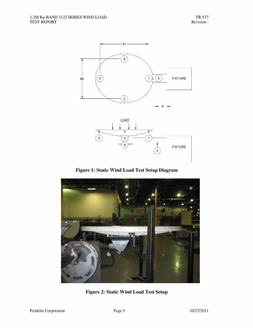
Install a reflector mount on to General Dynamic’s static wind loading fixture in the zenith position. Place digital indicators under the reflector at the major and minor extents. Measure and record the distance between the major dials and the distance between the minor dials. Place another indicator under the mast of the fixture to monitor fixture movement. See Figure 1 and Figure 2. For survival cases, the dials were removed and the antenna was inspected for failures after loading.
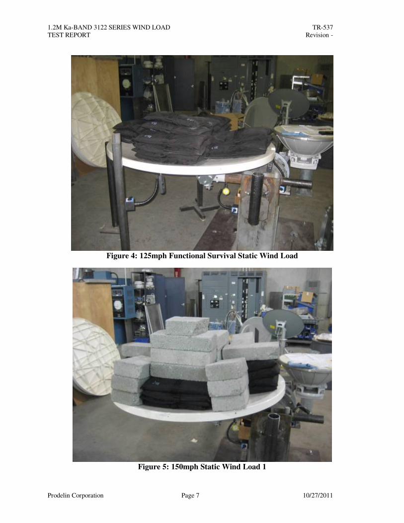
Operational: Apply wind load to the face of the reflector and record the dial indicator readings. Use these displacements to calculate an angular beam pointing error and operational gain loss. See Figure 3. Operational Survival: Apply wind load to the face of the reflector for 2 minutes. Remove the load and record the dial indicator readings. Use these displacements to calculate an angular beam pointing error and operational gain loss. Functional Survival (no damage preventing re-pointing): Apply 125mph wind load to the face of the reflector. After a minimum of 2 minutes, remove the load. Inspect the antenna system for any damage. See Figure 4. Ultimate Survival (no yielding or buckling failures): Apply 150mph wind load to the face of the reflector. After a minimum of 2 minutes, remove the load. Inspect the antenna system for any damage. See Figures 5, 6, and 7.
1.2M Ka-BAND 3122 SERIES WIND LOAD TR-537
TEST REPORT Revision -
Prodelin Corporation Page 5 10/27/2011
Figure 1: Static Wind Load Test Setup Diagram
Figure 2: Static Wind Load Test Setup
1.2M Ka-BAND 3122 SERIES WIND LOAD TR-537
TEST REPORT Revision -
Prodelin Corporation Page 6 10/27/2011
Wind Loads
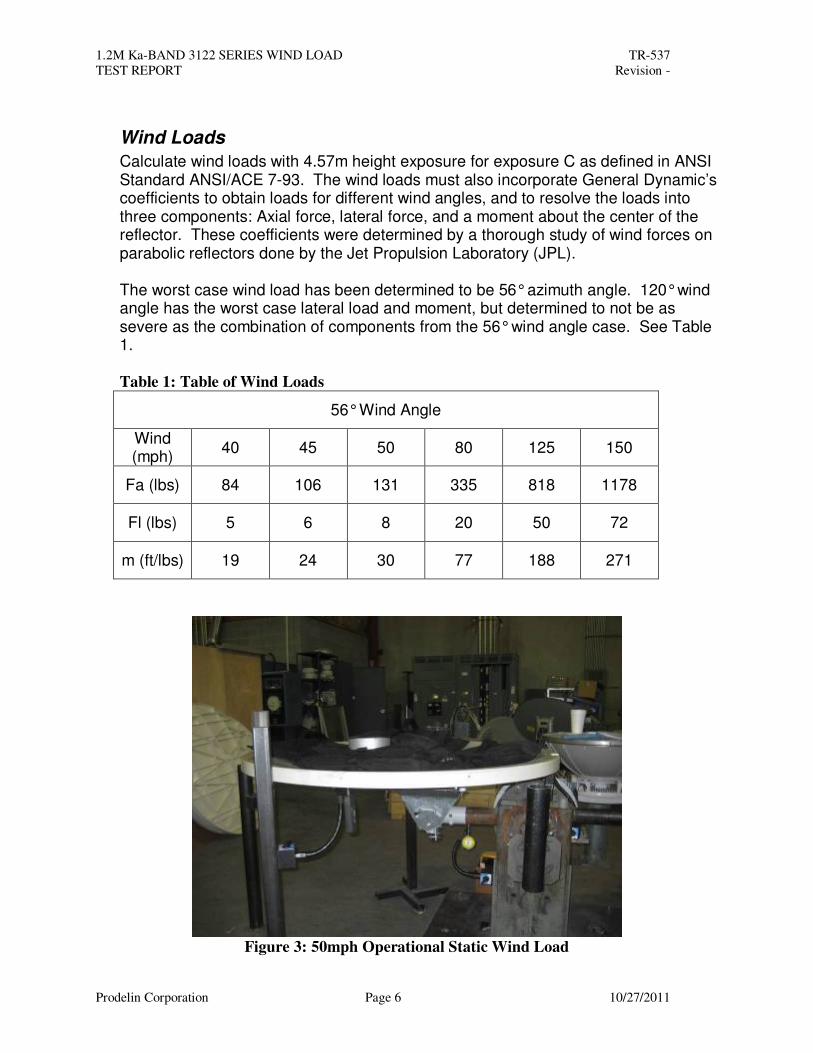
Calculate wind loads with 4.57m height exposure for exposure C as defined in ANSI Standard ANSI/ACE 7-93. The wind loads must also incorporate General Dynamic’s coefficients to obtain loads for different wind angles, and to resolve the loads into three components: Axial force, lateral force, and a moment about the center of the reflector. These coefficients were determined by a thorough study of wind forces on parabolic reflectors done by the Jet Propulsion Laboratory (JPL). The worst case wind load has been determined to be 56° azimuth angle. 120° wind angle has the worst case lateral load and moment, but determined to not be as severe as the combination of components from the 56° wind angle case. See Table 1. Table 1: Table of Wind Loads
56° Wind Angle
Wind (mph)
40 45 50 80 125 150
Fa (lbs) 84 106 131 335 818 1178
Fl (lbs) 5 6 8 20 50 72
m (ft/lbs) 19 24 30 77 188 271
Figure 3: 50mph Operational Static Wind Load
1.2M Ka-BAND 3122 SERIES WIND LOAD TR-537
TEST REPORT Revision -
Prodelin Corporation Page 7 10/27/2011
Figure 4: 125mph Functional Survival Static Wind Load
Figure 5: 150mph Static Wind Load 1
1.2M Ka-BAND 3122 SERIES WIND LOAD TR-537
TEST REPORT Revision -
Prodelin Corporation Page 8 10/27/2011
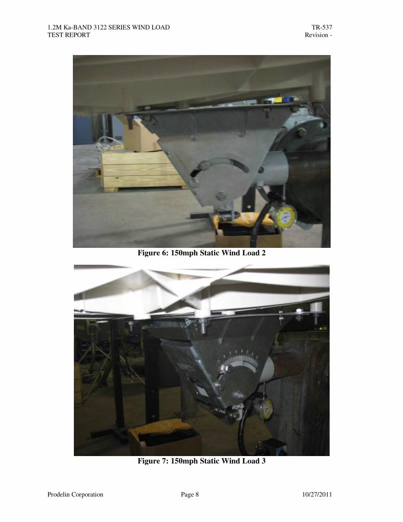
Figure 6: 150mph Static Wind Load 2
Figure 7: 150mph Static Wind Load 3
1.2M Ka-BAND 3122 SERIES WIND LOAD TR-537
TEST REPORT Revision -
Prodelin Corporation Page 9 10/27/2011
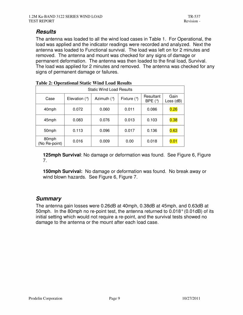
Results
The antenna was loaded to all the wind load cases in Table 1. For Operational, the load was applied and the indicator readings were recorded and analyzed. Next the antenna was loaded to Functional survival. The load was left on for 2 minutes and removed. The antenna and mount was checked for any signs of damage or permanent deformation. The antenna was then loaded to the final load, Survival. The load was applied for 2 minutes and removed. The antenna was checked for any signs of permanent damage or failures.
Table 2: Operational Static Wind Load Results
Static Wind Load Results
Case Elevation (°) Azimuth (°) Fixture (°) Resultant BPE (°)
Gain Loss (dB)
40mph 0.072 0.060 0.011 0.086 0.26
45mph 0.083 0.076 0.013 0.103 0.38
50mph 0.113 0.096 0.017 0.136 0.63
80mph (No Re-point)
0.016 0.009 0.00 0.018 0.01
125mph Survival: No damage or deformation was found. See Figure 6, Figure 7.
150mph Survival: No damage or deformation was found. No break away or wind blown hazards. See Figure 6, Figure 7.
Summary
The antenna gain losses were 0.26dB at 40mph, 0.38dB at 45mph, and 0.63dB at 50mph. In the 80mph no re-point test, the antenna returned to 0.018° (0.01dB) of its initial setting which would not require a re-point, and the survival tests showed no damage to the antenna or the mount after each load case.
1.2M Ka-BAND 3122 SERIES WIND LOAD TR-537
TEST REPORT Revision -
Prodelin Corporation Page 10 10/27/2011
3. Dynamic Wind Load Test
Antenna Wind Load Setup
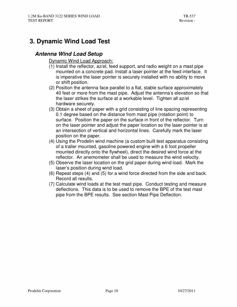
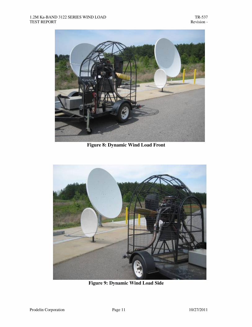
Dynamic Wind Load Approach: (1) Install the reflector, az/el, feed support, and radio weight on a mast pipe
mounted on a concrete pad. Install a laser pointer at the feed interface. It is imperative the laser pointer is securely installed with no ability to move or shift position.
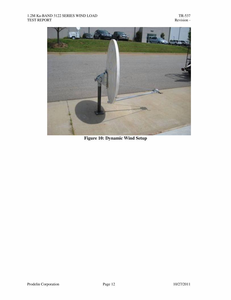
(2) Position the antenna face parallel to a flat, stable surface approximately 40 feet or more from the mast pipe. Adjust the antenna’s elevation so that the laser strikes the surface at a workable level. Tighten all az/el hardware securely.
(3) Obtain a sheet of paper with a grid consisting of line spacing representing 0.1 degree based on the distance from mast pipe (rotation point) to surface. Position the paper on the surface in front of the reflector. Turn on the laser pointer and adjust the paper location so the laser pointer is at an intersection of vertical and horizontal lines. Carefully mark the laser position on the paper.
(4) Using the Prodelin wind machine (a custom built test apparatus consisting of a trailer mounted, gasoline powered engine with a 6 foot propeller mounted directly onto the flywheel), direct the desired wind force at the reflector. An anemometer shall be used to measure the wind velocity.
(5) Observe the laser location on the grid paper during wind load. Mark the laser’s position during wind load.
(6) Repeat steps (4) and (5) for a wind force directed from the side and back. Record all results.
(7) Calculate wind loads at the test mast pipe. Conduct testing and measure deflections. This data is to be used to remove the BPE of the test mast pipe from the BPE results. See section Mast Pipe Deflection.
1.2M Ka-BAND 3122 SERIES WIND LOAD TR-537
TEST REPORT Revision -
Prodelin Corporation Page 11 10/27/2011
Figure 8: Dynamic Wind Load Front
Figure 9: Dynamic Wind Load Side
1.2M Ka-BAND 3122 SERIES WIND LOAD TR-537
TEST REPORT Revision -
Prodelin Corporation Page 12 10/27/2011
Figure 10: Dynamic Wind Setup
1.2M Ka-BAND 3122 SERIES WIND LOAD TR-537
TEST REPORT Revision -
Prodelin Corporation Page 13 10/27/2011
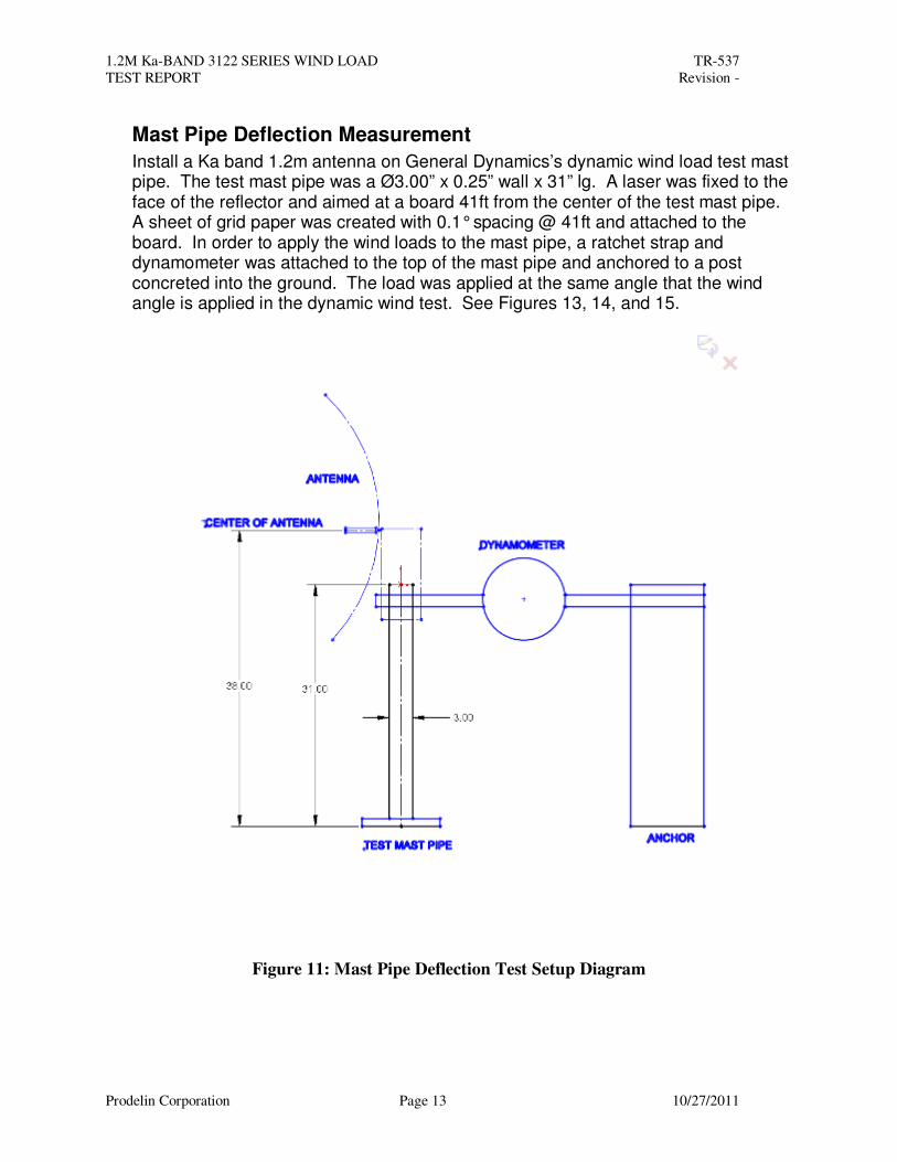
Mast Pipe Deflection Measurement
Install a Ka band 1.2m antenna on General Dynamics’s dynamic wind load test mast pipe. The test mast pipe was a Ø3.00” x 0.25” wall x 31” lg. A laser was fixed to the face of the reflector and aimed at a board 41ft from the center of the test mast pipe. A sheet of grid paper was created with 0.1° spacing @ 41ft and attached to the board. In order to apply the wind loads to the mast pipe, a ratchet strap and dynamometer was attached to the top of the mast pipe and anchored to a post concreted into the ground. The load was applied at the same angle that the wind angle is applied in the dynamic wind test. See Figures 13, 14, and 15.
Figure 11: Mast Pipe Deflection Test Setup Diagram
1.2M Ka-BAND 3122 SERIES WIND LOAD TR-537
TEST REPORT Revision -
Prodelin Corporation Page 14 10/27/2011
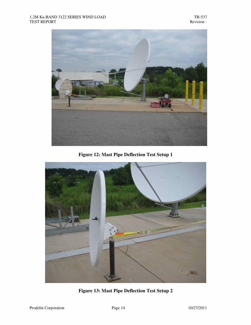
Figure 12: Mast Pipe Deflection Test Setup 1
Figure 13: Mast Pipe Deflection Test Setup 2
1.2M Ka-BAND 3122 SERIES WIND LOAD TR-537
TEST REPORT Revision -
Prodelin Corporation Page 15 10/27/2011
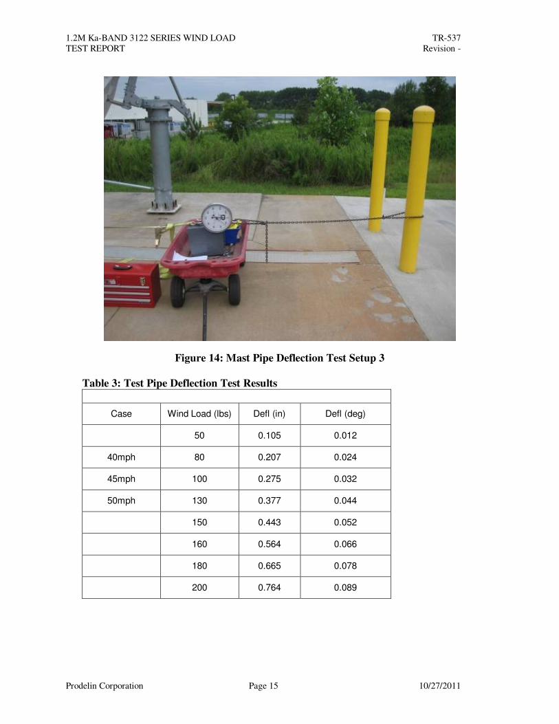
Figure 14: Mast Pipe Deflection Test Setup 3
Table 3: Test Pipe Deflection Test Results
Case Wind Load (lbs) Defl (in) Defl (deg)
50 0.105 0.012
40mph 80 0.207 0.024
45mph 100 0.275 0.032
50mph 130 0.377 0.044
150 0.443 0.052
160 0.564 0.066
180 0.665 0.078
200 0.764 0.089
1.2M Ka-BAND 3122 SERIES WIND LOAD TR-537
TEST REPORT Revision -
Prodelin Corporation Page 16 10/27/2011
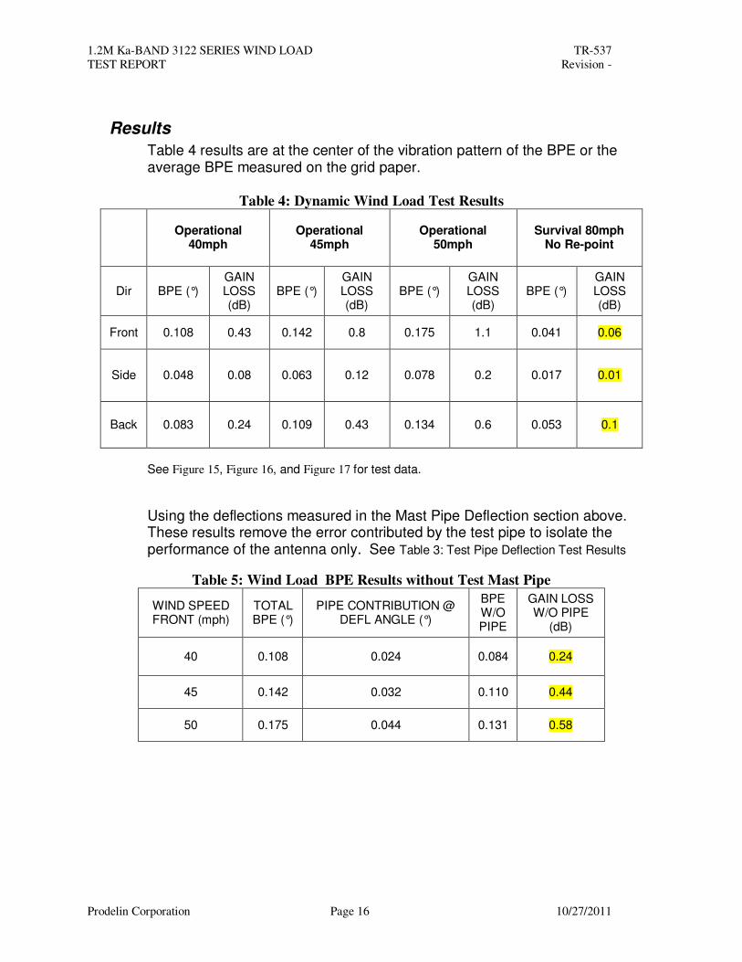
Results
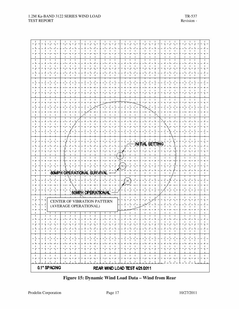
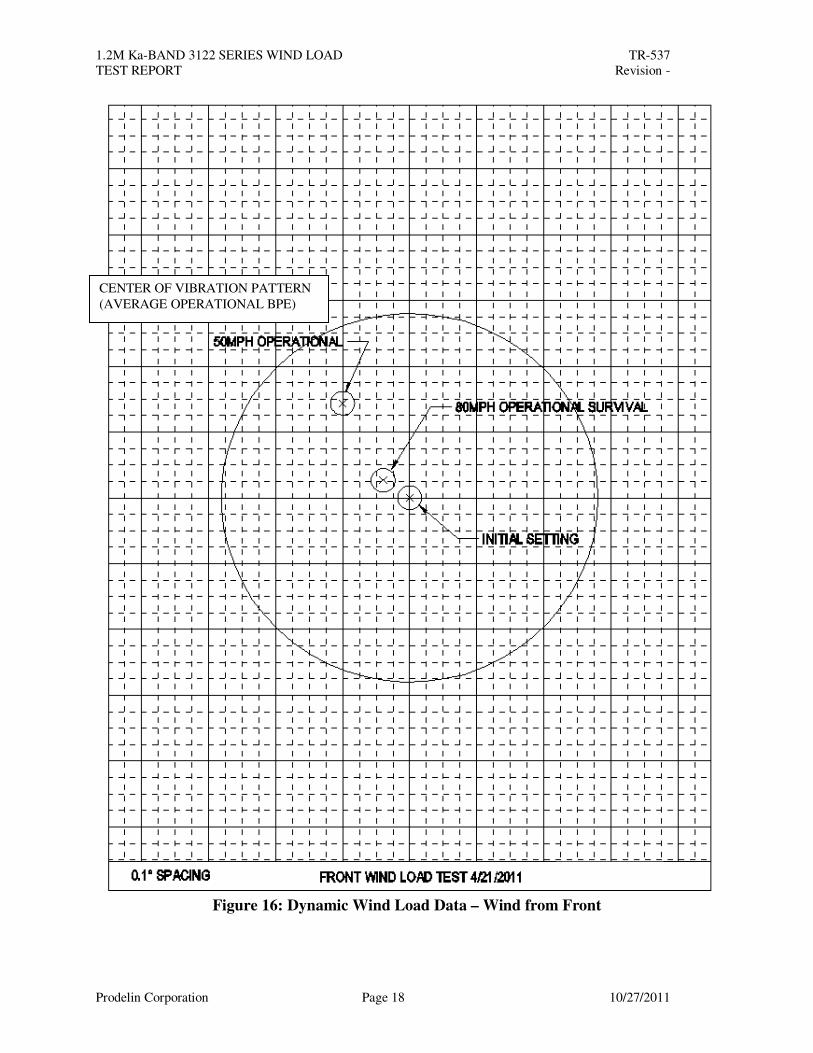
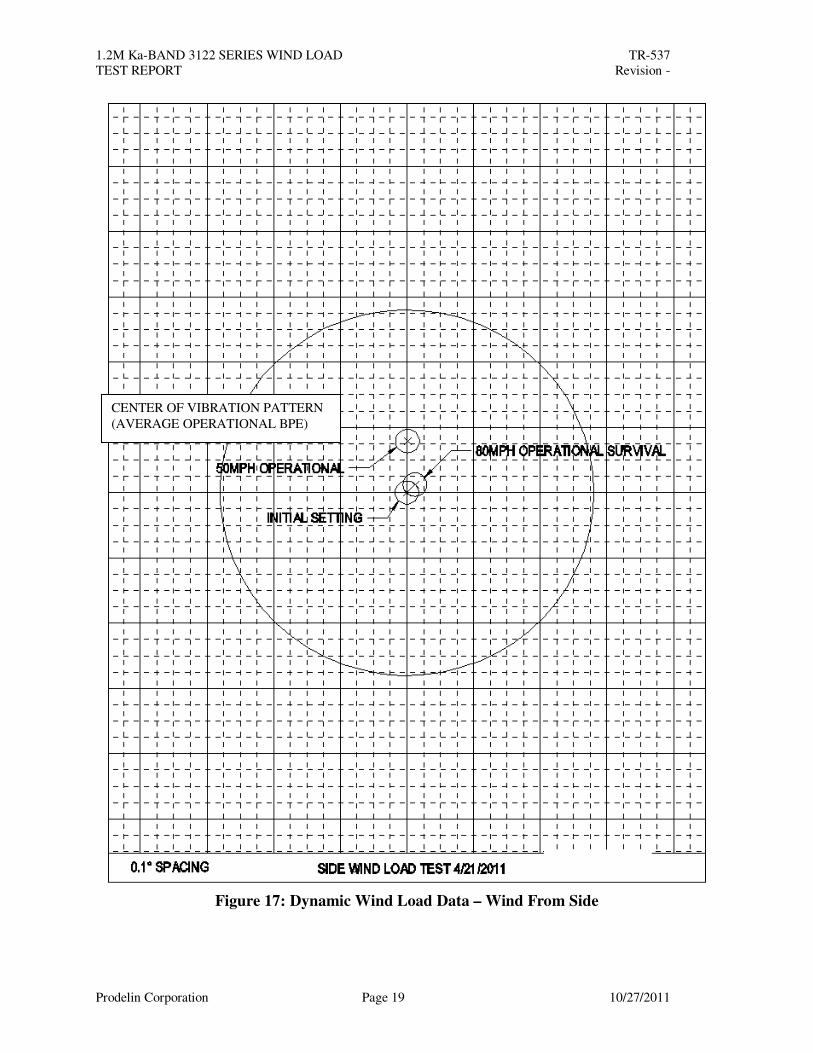
Table 4 results are at the center of the vibration pattern of the BPE or the average BPE measured on the grid paper.
Table 4: Dynamic Wind Load Test Results
Operational
40mph Operational
45mph Operational
50mph Survival 80mph
No Re-point
Dir BPE (°) GAIN LOSS (dB)
BPE (°) GAIN LOSS (dB)
BPE (°) GAIN LOSS (dB)
BPE (°) GAIN LOSS (dB)
Front 0.108 0.43 0.142 0.8 0.175 1.1 0.041 0.06
Side 0.048 0.08 0.063 0.12 0.078 0.2 0.017 0.01
Back 0.083 0.24 0.109 0.43 0.134 0.6 0.053 0.1
See Figure 15, Figure 16, and Figure 17 for test data.
Using the deflections measured in the Mast Pipe Deflection section above. These results remove the error contributed by the test pipe to isolate the performance of the antenna only. See Table 3: Test Pipe Deflection Test Results
Table 5: Wind Load BPE Results without Test Mast Pipe
WIND SPEED FRONT (mph)
TOTALBPE (°)
PIPE CONTRIBUTION @ DEFL ANGLE (°)
BPE W/O PIPE
GAIN LOSS W/O PIPE
(dB)
40 0.108 0.024 0.084 0.24
45 0.142 0.032 0.110 0.44
50 0.175 0.044 0.131 0.58
1.2M Ka-BAND 3122 SERIES WIND LOAD TR-537
TEST REPORT Revision -
Prodelin Corporation Page 17 10/27/2011
Figure 15: Dynamic Wind Load Data – Wind from Rear
CENTER OF VIBRATION PATTERN
(AVERAGE OPERATIONAL)
1.2M Ka-BAND 3122 SERIES WIND LOAD TR-537
TEST REPORT Revision -
Prodelin Corporation Page 18 10/27/2011
Figure 16: Dynamic Wind Load Data – Wind from Front
CENTER OF VIBRATION PATTERN
(AVERAGE OPERATIONAL BPE)
1.2M Ka-BAND 3122 SERIES WIND LOAD TR-537
TEST REPORT Revision -
Prodelin Corporation Page 19 10/27/2011
Figure 17: Dynamic Wind Load Data – Wind From Side
CENTER OF VIBRATION PATTERN
(AVERAGE OPERATIONAL BPE)
1.2M Ka-BAND 3122 SERIES WIND LOAD TR-537
TEST REPORT Revision -
Prodelin Corporation Page 20 10/27/2011
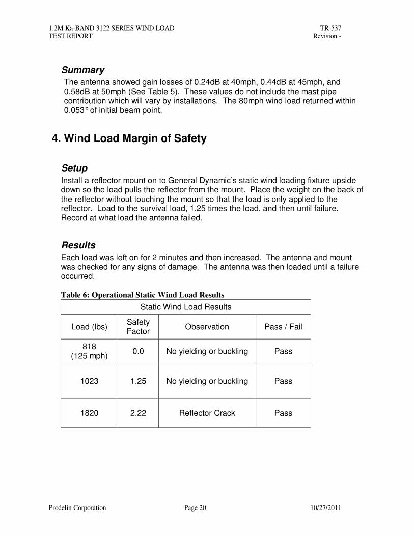
Summary
The antenna showed gain losses of 0.24dB at 40mph, 0.44dB at 45mph, and 0.58dB at 50mph (See Table 5). These values do not include the mast pipe contribution which will vary by installations. The 80mph wind load returned within 0.053° of initial beam point.
4. Wind Load Margin of Safety
Setup
Install a reflector mount on to General Dynamic’s static wind loading fixture upside down so the load pulls the reflector from the mount. Place the weight on the back of the reflector without touching the mount so that the load is only applied to the reflector. Load to the survival load, 1.25 times the load, and then until failure. Record at what load the antenna failed.
Results
Each load was left on for 2 minutes and then increased. The antenna and mount was checked for any signs of damage. The antenna was then loaded until a failure occurred.
Table 6: Operational Static Wind Load Results
Static Wind Load Results
Load (lbs) Safety Factor
Observation Pass / Fail
818 (125 mph)
0.0 No yielding or buckling Pass
1023 1.25 No yielding or buckling Pass
1820 2.22 Reflector Crack Pass
1.2M Ka-BAND 3122 SERIES WIND LOAD TR-537
TEST REPORT Revision -
Prodelin Corporation Page 21 10/27/2011
Summary
Survival 1.25 Safety Factor: The antenna was loaded to a factor of 1.25 times the survival load and had no yielding or buckling.
Survival Margin of Safety: The antenna was loaded until a failure occurred. The antenna was loaded to 1820lbs at which reflector ribs began to crack. This is considered to be a failure, however the antenna still did not break apart or become a wind blown hazard. The reflector failed at a safety factor of 2.22 times the survival load requirement.
5. Conclusions This document reports the 1.2m Ka band antenna performance at 40, 45, and 50mph and its survival capabilities. The antenna has worst case gain losses of 0.26dB at 40mph, 0.38dB at 45mph, and 0.63dB at 50mph. After being introduced to an 80mph wind, the antenna returned within 0.053 (0.1dB), which should not warrant a re-point condition. For survival, the antenna exceeded 125mph wind loading by a safety factor of 2.22.