statistical analysis of mux-based physical unclonable
TRANSCRIPT

1
Statistical Analysis of MUX-based PhysicalUnclonable Functions
Yingjie Lao, Student Member, IEEE, and Keshab K. Parhi, Fellow, IEEE
Abstract—Physical unclonable functions (PUFs) can store se-cret keys in integrated circuits (ICs) by exploiting the uncon-trollable randomness due to manufacturing process variations.These PUFs can be used for authentication of devices and forkey generation in security applications. This paper presents arigorous statistical analysis of various types of multiplexer-based(MUX-based) PUFs including the original MUX PUF, the feed-forward MUX PUFs, the modified feed-forward MUX PUFs, andmultiplexer-demultiplexer (MUX/DeMUX) PUF. The modifiedfeed-forward MUX PUF structure is a new structure that isintroduced in this paper. Three types of feed-forward PUFs areanalyzed in this paper. These include feed-forward overlap, feed-forward cascade and feed-forward separate. The performanceanalysis quantifies inter-chip and intra-chip variations as afunction of the number of stages, the process variation variance,the environmental noise variance, and the arbiter skew fordifferent PUFs. Three other metrics of performance are alsointroduced and analyzed in this paper; these include reliability,uniqueness and randomness. A PUF is more reliable if it hasless intra-chip variation. A PUF is more unique if the inter-chip variation is closer to 50%. A PUF is more random if itsresponse bit is 0 or 1 with equal probability. Our statisticalanalysis shows that the intra-chip variation is less dependenton the number of stages, N, if N is greater than 10. However,the inter-chip variation is dependent on N if N is less than 100.It is shown that the feed-forward PUFs have higher intra-chipvariation than MUX PUFs; however, the modified feed-forwardPUFs have significantly lower intra-chip variation than the feed-forward PUFs. It is shown that the modified feed-forward cascadeMUX PUF has the best uniqueness and randomness, while theoriginal MUX PUF has the best reliability. The analysis presentedin this paper can be used by the designer to choose an appropriatePUF based on the application’s requirement. This eliminates theneed for fabrication and testing of many PUFs for selecting anappropriate PUF.
Index Terms—Physical Unclonable Function, Multiplexer-based Structures, Statistical Analysis, Feed-Forward MUXPUF, Reliability, Randomness, Uniqueness, Intra-Chip Variation,Inter-Chip Variation.
I. INTRODUCTION
Physical Unclonable Functions (PUFs) [1]–[3] are novelsecurity primitives which store secret keys in physical objectsby exploiting the uncontrollable randomness due to manufac-turing process variations. PUFs generate signatures based onthe unique intrinsic uncontrollable physical features, which canthen be used for hardware authentication or the generationof secret keys. Contrary to standard digital systems, PUFsextract secrets from complex properties of a physical materialrather than storing them in a non-volatile memory. It is nearlyimpossible to predict, clone or duplicate PUFs. Furthermore,an adversary cannot easily mount an attack to counterfeit the
The authors are with the Department of Electrical and Computer En-gineering, University of Minnesota, Minneapolis, MN 55455 USA (email:[email protected]; [email protected]).
Copyright (c) 2013 IEEE. Personal use of this material is permitted.However, permission to use this material for any other purposes must beobtained from the IEEE by sending an email to [email protected].
secret information without changing the physical randomness.Based on these advantages, PUFs can efficiently and reliablygenerate volatile secret keys for cryptographic operations andenable lightweight and cost-effective authentication of ICs.
The performance of a PUF depends on both process varia-tions and environmental conditions. Designing a PUF that isclose to truly random in nature and that can operate reliablyover a wide range of operating conditions is still a challenge.Some metrics have been introduced to evaluate the perfor-mances of PUFs by analyzing the outputs of PUF instances.These considered metrics include reliability, uniqueness, andrandomness. PUF reliability captures how efficient a PUFis in reproducing the response bits of an IC chip. Whenthe same challenge is applied repetitively to a MUX-basedPUF, the responses are expected to be identical. Uniquenessrepresents the ability of a PUF to uniquely distinguish aparticular chip among a group of chips of the same type.When the same challenge sets are applied to different PUFs,the output responses are expected to be different. Ideally, theHamming distances between the responses of different PUFsshould be 50%. Randomness indicates the unbiasedness of thePUF response. However, these metrics need to be characterizedover a large population of chips to validate the effectiveness ofPUFs. This can involve a long and costly chip manufacturingprocess followed by many measurements after the circuitsare fabricated. Furthermore, since the manufacturing processvariation and the environmental variation are uncontrollable,it is hard to get a very accurate estimation of the performanceduring the design stage. Note that security is another perfor-mance metric of PUFs, which is not addressed in this paper.A PUF is more secure, if an adversary finds it harder to breakin.
Knowledge about the circuit-level behavior such as pro-cess variation pattern, variation of circuit parameters (e.g.,delay, threshold voltage) over changing operating conditionscould help designers to predict the performance comparisonsamong different PUF designs. Conducting the performancecomparison among detailed PUF designs before fabricationwould guarantee robust on-chip PUF performance. Monte-Carlo simulations of netlists that take process and environmentvariations into account can be used for this purpose. Thesesimulations can provide approximate results, which can beused as indicators of the true performances of different PUFs.An alternate approach to evaluate the performance of thePUFs is by modeling the physical components of PUFs ina statistical manner. A number of such efforts have beendeveloped in the literature. Statistical analysis on CoatingPUF has been presented in [4]. In [5], entropy analysis ofOptical PUF has been discussed. The statistical models ofRing Oscillator PUF [6], [7] and MUX PUFs [8]–[10] havealso been studied in the literature. Additionally, the workin [11] relates the statistical analysis of PUFs to circuit-level optimization and architecture-level optimization, which

2
leads to interesting results that could improve the design andimplementation of reliable and efficient PUFs.
The objective of this paper is to theoretically comparethe performances of different MUX-based PUFs to predictthe relative advantages of various MUX-based PUF designs.In previous works, such as the efforts in [8]–[10], only thestatistical modeling with respect to the input-output mappingsof PUF structures was presented. However, theoretical per-formances of PUFs based on these models were not studied.Additionally, there seems little consensus about which PUF ismore suitable for a specific application or a particular device inthe existing literature. The work presented in this paper differsfrom existing efforts in several respects. First, to the best of ourknowledge, this paper, for the first time, presents a systematicstatistical analysis of the performances of various MUX-basedPUFs. These include the original MUX PUF, feed-forwardMUX PUFs, and multiplexer-demultiplexer (MUX/DeMUX)PUF. Moreover, the focus of our work is on the comparisonof performance of various MUX PUFs, which could help thedesigner to select an appropriate PUF during the design stage.Finally, instead of only modeling the structures of variousMUX-based PUFs, statistical analysis is performed to providea deeper insight into the nature of these PUFs. Equations aboutthe PUF performances are derived; these equations allow thedesigner to estimate the PUF performance metrics theoreti-cally. In addition, we also introduce a class of modified feed-forward MUX PUFs obtained by modifying the standard feed-forward path. These structures are also analyzed statistically. Itis shown that the modified feed-forward MUX PUFs have lessintra-chip variations than standard feed-forward MUX PUFs.
The rest of the paper is organized as follows. In SectionII, we introduce the background of MUX-based PUFs andtheir applications. In Section III, we present several modifiedfeed-forward PUF structures by employing the proposed novelmodified feed-forward path. Section IV defines the metricindicators of PUF performance. Section V describes statisticalmodeling of the physical components in a MUX-based PUF,and then presents the statistical analysis results of the originalMUX PUF. These results are also validated by comparing withexperimental results. In Section VI, we analyze the statisticalproperties of feed-forward MUX PUFs and MUX/DeMUXPUF from the perspectives of the defined performance indica-tors. We summarize the performance comparisons of variousMUX-based PUFs in Section VII. Section VIII validates thestatistical analysis results by experimental results using SPICEsimulations. Finally, Section IX concludes the paper.
II. BACKGROUND
A. Silicon MUX PUF
There are several subtypes of PUFs, each with its ownapplications and security features. A major type is the so-called silicon PUFs, which exploit the delay variations ofcircuit components to generate a unique signature for each IC.Silicon PUFs can be integrated into chips very conveniently,since these are implemented with standard digital logic and donot require any special fabrication. The examples of SiliconPUFs include: Multiplexer (MUX) PUF [12], Ring OscillatorPUF [2], SRAM PUF [13] and Butterfly PUF [14].
A MUX PUF is an example of a ”Strong” PUF [15] that isunclonable due to manufacturing process variations, and canaccommodate many possible challenge-response pairs (CRPs).
As illustrated in Fig. 1, in a MUX PUF, each challenge createstwo paths through the circuit that are excited simultaneously.The output is generated according to the delay differencebetween the two paths. A MUX PUF consists of N stagesof MUXs and one arbiter which connects the last stage ofthe two paths. MUXs in each stage act as a switch to eithercross or straight propagate the rising edge signals, basedon the corresponding challenge bit. Each MUX should bedesigned equivalently, while variations will be introducedduring manufacturing process. Finally, the arbiter translatesthe analog timing difference into a digital value. For instance,if the rising edge signal arrives at the top input of the arbiterearlier than the signal arriving at the bottom input, the outputwill be one; otherwise, if it reaches the bottom path first,the output will be zero. The output response depends on theapplied challenge bits and will be permanent for each IC afterfabrication or only vary in a small range due to environmentalvariations.
For transistors, manufacturing randomness exists due tovariations in transistor length, width, gate oxide thickness,doping concentration density, body bias, metal width, metalthickness, and ILD (inter-level dielectric) thickness, etc [16].These manufacturing variations lead to a significant amountof variability for the MUX-based PUFs, which are sufficientto generate unique challenge-response pairs for each IC bycomparing the delays of two paths.
0
0 0
1 1
0
1 1
0
0
1
1
. . .
Challenge
ArbiterOutput
Fig. 1. Silicon MUX Physical Unclonable Function.
B. Feed-Forward MUX PUF
In order to improve the security, a feed-forward structurehas been proposed in [17] to add non-linearity into the originalMUX PUF. In a feed-forward MUX PUF, the output of afeed-forward arbiter (FF arbiter) from an intermediate stage isused as a challenge to a subsequent stage. Fig. 2 shows onebasic structure of the feed-forward MUX PUF, which uses theracing result of an intermediate stage as the select signal fora later MUX stage. This structure increases the complexity ofnumerical modeling attacks [18]. However, the reliability ofthe PUF has been degraded since some select signals of theMUXs may also be affected by environmental variations.
0
0 0
1 1
0
1 1
0
0
1
1
. . .
ChallengeFF Arbiter
0
0
1
1
ArbiterOutput
. . .
Fig. 2. Feed-Forward MUX PUF Structure.

3
C. MUX-based Reconfigurable PUFs
Based on the MUX PUF and its feed-forward variants,we have proposed several novel reconfigurable PUFs [19],[20], where the challenge-response pairs (CRPs) can be re-configured. Reconfigurable PUFs satisfy the updatable keyrequirement for PUF-based authentication systems. Further-more, reconfigurability improves the security against modelingattacks by limiting the amount of information leaked foreach configuration. Such architectures are classified into twocategories:
(a) CRP-Reconfigurable PUF: The challenge-response pairsare reconfigured directly by adding some additionalconfigure circuits into the structure, but without con-figuring the main PUF structure. This can be achievedby pre-processing the challenge before applying to thePUF or pre-processing the response before using it forauthentication.
(b) Logic-Reconfigurable PUF: The underlying logic of thePUF circuit is reconfigured in these structures; therefore,the challenge-response pairs are reconfigured.
Logic-Reconfigurable PUFs have better performance froma security perspective, as reconfiguration leads to a d-ifferent mathematical model of the PUF circuit, whilethe CRP-Reconfigurable PUFs only update the CRPs. TheCRP-Reconfigurable PUFs are not studied in this paper.The examples of Logic-Reconfigurable PUFs include Logic-Reconfigurable Feed-Forward MUX PUF, and MUX/DeMUXPUF.
1) Logic-Reconfigurable Feed-Forward MUX PUF:In [19], [20], we had introduced three different types of feed-forward MUX PUFs. These structures include Feed-ForwardOverlap (FFO), Feed-Forward Cascade (FFC), and Feed-Forward Separate (FFS). These structures are classified by thenature of interconnections of various feed-forward patterns inthese PUFs. We had also shown that the performance of a feed-forward MUX PUF depends on locations and the number offeed-forward paths (sometimes referred as feed-forward loopsin the literature [18]). The three feed-forward structures aredescribed below.
(a) Feed-Forward Overlap (FFO): this structure has at leastone stage overlap between two feed-forward paths asillustrated in Fig. 3.
(b) Feed-Forward Cascade (FFC): the ending stage of afeed-forward path will be the starting stage of anotherfeed-forward path. This is illustrated in Fig. 4.
(c) Feed-Forward Separate (FFS): different feed-forwardpaths are separate; thus, no stage overlap exists betweenthe two feed-forward paths. This is illustrated in Fig. 5.
0
0 0
1 1
0
1 1
0
0
1
1
. . .
Challenge FF Arbiter
0
0
1
1
ArbiterOutput
. . .
0
0
1
1
FF Arbiter
0
0
1
1
. . . . . .
Fig. 3. Feed-Forward MUX PUF Overlap Structure.
We have simulated these three feed-forward structures andhave shown that these structures satisfy different inter-chip andintra-chip characteristics [19], [20]. Based on this property,we have proposed a Logic-Reconfigurable Feed-forward MUX
0
0 0
1 1
0
1 1
0
0
1
1
. . .
ChallengeFF Arbiter
0
0
1
1
ArbiterOutput
. . .
0
0
1
1
FF Arbiter
. . .
Fig. 4. Feed-Forward MUX PUF Cascade Structure.
0
0 0
1 1
0
1 1
0
0
1
1
. . .
ChallengeFF Arbiter
0
0
1
1
ArbiterOutput
. . .
0
0
1
1
FF Arbiter
0
0
1
1
. . . . . .
Fig. 5. Feed-Forward MUX PUF Separate Structure.
PUF, which can be configured to any of these three differentstructures (i.e., FFO, FFC, and FFS) [19], [20].
2) MUX/DeMUX PUF: Another MUX-based Logic-Reconfigurable PUF is the MUX/DeMUX PUF, which altersthe PUF logic by using DeMUX. DeMUX enables the circuitto select the direction of the propagating signals, and makesthe original MUX PUF reconfigurable.
A basic structure is shown in Fig. 6. Instead of propagatingthe rising edge signal successively, some stages can be skippedby the DeMUX, which allows the challenge-response behaviorto be reconfigurable.
0
0 0
1 1
0
1 1
0
0
1
1
Challenge
0
0
1
1
ArbiterOutput
. . .
0
0
1
1
0
0
1
1
. . .
0
0
1
1
Select Signal
Fig. 6. MUX/DeMUX PUF.
III. MODIFIED FEED-FORWARD MUX PUFS
A. Modified Feed-Forward PathIn this paper, we propose a novel modified feed-forward
MUX PUF structure shown in Fig. 7, which is motivated byour statistical analysis results. In this structure, the output ofa feed-forward arbiter from an intermediate stage is inputas the challenge bit to two consecutive late MUX stages.By employing this modified feed-forward path, the reliabilityof the feed-forward PUF structure can be improved, whilethe same level of security will be retained. This structure isanalyzed statistically in this paper.
0
0 0
1 1
0
1 1
0
0
1
1
. . .
FF Arbiter
0
0
1
1
ArbiterOutput
. . .
0
0
1
1
Fig. 7. Modified Feed-Forward MUX PUF Structure.
The complexity of the modified feed-forward MUX PUFscan be further improved by using several modified feed-forward paths in a PUF circuit. Note that if we want to
4
maintain the length of challenge bits as N , we need to increasethe number of MUX stages to N +2M for the modified feed-forward structure, compared to N +M of the standard feed-forward PUF, where M represents the number of feed-forwardpaths. Additionally, the design overhead will also include Marbiters for both the standard feed-forward MUX PUF and themodified feed-forward MUX PUF.
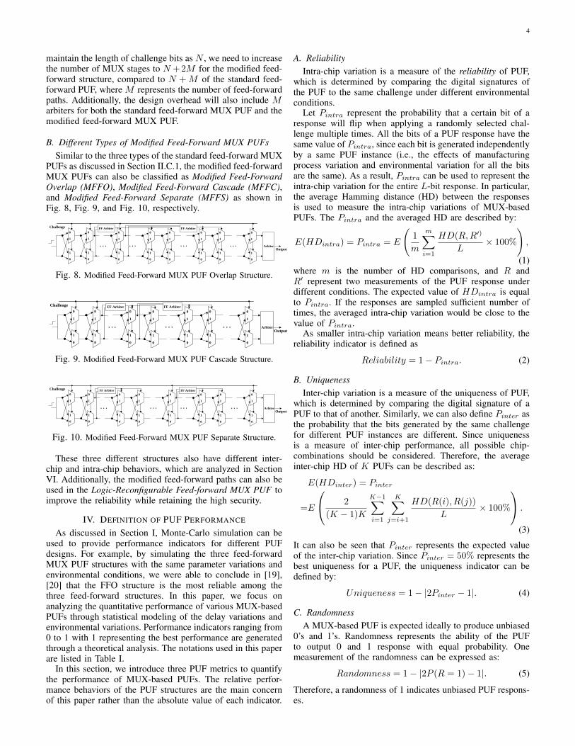
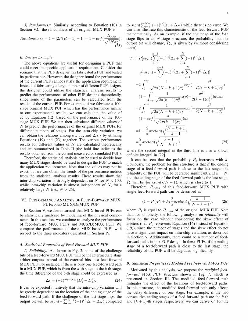
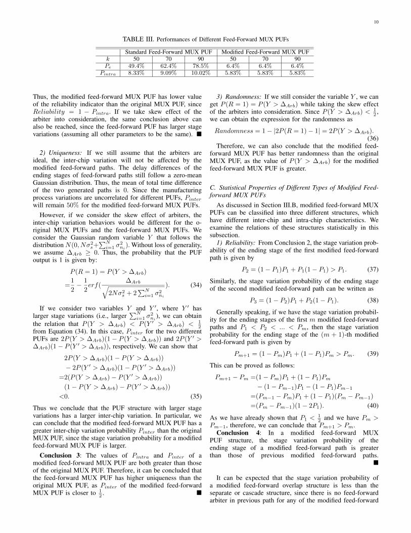
B. Different Types of Modified Feed-Forward MUX PUFsSimilar to the three types of the standard feed-forward MUX
PUFs as discussed in Section II.C.1, the modified feed-forwardMUX PUFs can also be classified as Modified Feed-ForwardOverlap (MFFO), Modified Feed-Forward Cascade (MFFC),and Modified Feed-Forward Separate (MFFS) as shown inFig. 8, Fig. 9, and Fig. 10, respectively.
0
0 0
1 1
0
1 1
0
0
1
1
. . .
Challenge FF Arbiter
0
0
1
1
ArbiterOutput
. . .
0
0
1
1
FF Arbiter
0
0
1
1
. . . . . .
0
0
1
1
0
0
1
1
Fig. 8. Modified Feed-Forward MUX PUF Overlap Structure.
0
0 0
1 1
0
1 1
0
0
1
1
. . .
Challenge FF Arbiter
0
0
1
1
ArbiterOutput
. . .
0
0
1
1
FF Arbiter
. . .
0
0
1
1
0
0
1
1
Fig. 9. Modified Feed-Forward MUX PUF Cascade Structure.
0
0 0
1 1
0
1 1
0
0
1
1
. . .
ChallengeFF Arbiter
0
0
1
1
ArbiterOutput
. . .
0
0
1
1
FF Arbiter
0
0
1
1
. . . . . .
0
0
1
1
0
0
1
1
Fig. 10. Modified Feed-Forward MUX PUF Separate Structure.
These three different structures also have different inter-chip and intra-chip behaviors, which are analyzed in SectionVI. Additionally, the modified feed-forward paths can also beused in the Logic-Reconfigurable Feed-forward MUX PUF toimprove the reliability while retaining the high security.
IV. DEFINITION OF PUF PERFORMANCE
As discussed in Section I, Monte-Carlo simulation can beused to provide performance indicators for different PUFdesigns. For example, by simulating the three feed-forwardMUX PUF structures with the same parameter variations andenvironmental conditions, we were able to conclude in [19],[20] that the FFO structure is the most reliable among thethree feed-forward structures. In this paper, we focus onanalyzing the quantitative performance of various MUX-basedPUFs through statistical modeling of the delay variations andenvironmental variations. Performance indicators ranging from0 to 1 with 1 representing the best performance are generatedthrough a theoretical analysis. The notations used in this paperare listed in Table I.
In this section, we introduce three PUF metrics to quantifythe performance of MUX-based PUFs. The relative perfor-mance behaviors of the PUF structures are the main concernof this paper rather than the absolute value of each indicator.
A. ReliabilityIntra-chip variation is a measure of the reliability of PUF,
which is determined by comparing the digital signatures ofthe PUF to the same challenge under different environmentalconditions.
Let Pintra represent the probability that a certain bit of aresponse will flip when applying a randomly selected chal-lenge multiple times. All the bits of a PUF response have thesame value of Pintra, since each bit is generated independentlyby a same PUF instance (i.e., the effects of manufacturingprocess variation and environmental variation for all the bitsare the same). As a result, Pintra can be used to represent theintra-chip variation for the entire L-bit response. In particular,the average Hamming distance (HD) between the responsesis used to measure the intra-chip variations of MUX-basedPUFs. The Pintra and the averaged HD are described by:
E(HDintra) = Pintra = E
(1
m
m∑i=1
HD(R,R′)
L× 100%
),
(1)where m is the number of HD comparisons, and R andR′ represent two measurements of the PUF response underdifferent conditions. The expected value of HDintra is equalto Pintra. If the responses are sampled sufficient number oftimes, the averaged intra-chip variation would be close to thevalue of Pintra.
As smaller intra-chip variation means better reliability, thereliability indicator is defined as
Reliability = 1− Pintra. (2)
B. UniquenessInter-chip variation is a measure of the uniqueness of PUF,
which is determined by comparing the digital signature of aPUF to that of another. Similarly, we can also define Pinter asthe probability that the bits generated by the same challengefor different PUF instances are different. Since uniquenessis a measure of inter-chip performance, all possible chip-combinations should be considered. Therefore, the averageinter-chip HD of K PUFs can be described as:
E(HDinter) = Pinter
=E
2
(K − 1)K
K−1∑i=1
K∑j=i+1
HD(R(i), R(j))
L× 100%
.
(3)
It can also be seen that Pinter represents the expected valueof the inter-chip variation. Since Pinter = 50% represents thebest uniqueness for a PUF, the uniqueness indicator can bedefined by:
Uniqueness = 1− |2Pinter − 1|. (4)
C. RandomnessA MUX-based PUF is expected ideally to produce unbiased
0’s and 1’s. Randomness represents the ability of the PUFto output 0 and 1 response with equal probability. Onemeasurement of the randomness can be expressed as:
Randomness = 1− |2P (R = 1)− 1|. (5)
Therefore, a randomness of 1 indicates unbiased PUF respons-es.

5
TABLE I. Notation Used in the Paper
Notation ExplanationN Number of MUX stages in a PUF instanceM Number of feed-forward pathsL Length of a responseCi Challenge bit of the i-th MUX stageDt
i Delay of the top element of the i-th MUX stageDb
i Delay of the bottom element of the i-th MUX stage∆i Delay difference between top and bottom elements of the i-th MUX stage
∆Arb Skew effect of the arbiterrN Delay difference of N stagesR Response
V. PERFORMANCE ANALYSIS OF THE ORIGINAL MUXPUF
A. Physical Component Modeling of MUX-based PUFsAs shown in Fig. 1, a MUX PUF consists of a sequence of
MUXs and an arbiter. The rising edge signal excites the twopaths at the first stage simultaneously. The actual propagatedpaths are determined by the external challenge bits. After thelast stage, the arbiter will generate the output bit by comparingthe arrival time of the two paths at its input. It has becomestandard to model the MUX PUF via an additive linear delaymodel [8], [9]. According to the efforts in the field of statisticalstatic timing analysis (SSTA) [16], the manufacturing processvariations for the parameters of transistors can be modeled asGaussian distributions. As a result, the variations of the delayswill also be approximately Gaussian.
Process variations are classified as follows: inter-die vari-ations are the variations from die to die, while intra-dievariations correspond to variability within a single chip. Inter-die variations affect all devices on the same chip similarly,while intra-die variations affect different devices differentlyon the same chip. A very widely used model for delayspatial correlation is the ”grid model” [16], which assumesperfect correlations among the devices in the same grid, highcorrelations among those in nearby grids, and low or zerocorrelations in faraway grids, since devices close to each otherare more likely to have similar characteristics than those placedfar away.
Additionally, experimental results in [12] have alreadyshown that the inter-chip variation for MUX PUF across thewafers is similar to that within a single wafer, as the outputof the arbiter in silicon MUX PUF is only based on thedifference of two selected paths. Therefore, these die-to-die,wafer-to-wafer, and lot-to-lot manufacturing variations willhave minimum effect on the output response.
Based on the facts discussed above, for simplicity, we canmodel the delay of each single MUX as an independentidentically distributed (i.i.d.) random variable Di, modeled bya Gaussian random variable N(µ, σ2), where µ represents themean and σ represents the standard deviation of the delayof each MUX. Therefore, the total delay of the N stages ismodeled by N(Nµ,Nσ2). The delay difference between topand bottom MUXs of the i-th stage will also follow a Gaussiandistribution, and can be expressed as:
∆i = Dti −Db
i ∼ N(0, 2σ2). (6)
For the original MUX PUF, the response is dependent onthe delay difference of the two selected paths. The sign of thedelay difference of each stage is determined by the external
challenge bits. Consequently, the delay difference after the laststage can be modeled as
rN =
N∑i=1
(−1)C′i∆i, (7)
where C ′i = ⊕Nj=i+1Cj and C ′N = 0. The output bit isgenerated by
R = sign(rN ) =
{1, rN ≥ 0
0, rN < 0. (8)
It can be seen that the original MUX PUF forms an additivelinear model.
In a real PUF circuit, the arbiter would not be ideal. Theskew effect of the arbiters also affects the performance ofMUX-based PUFs by reducing the uniqueness, producing abiased response, and even degrading the security. If we assumethat the threshold of the arbiter is ∆Arb, the response is givenby
R = sign(rN ) =
{1, rN ≥ ∆Arb
0, rN < ∆Arb, (9)
since the arbiter is preset to 0 and requires a setup timeconstraint to switch to 1.
B. Probability Distribution of Output Delay Difference
Fig. 11 shows a scatter plot of output samples from thesimulations of 100-stage original MUX PUFs. Note that thereare overlaps between the regions of output 1’s and output 0’s,which makes it difficult to estimate ∆Arb accurately. Thiscould be because the measured delay differences (measuredfor each path at the 50% point in the transition) and the actualdelay differences that the arbiter operates at are different. Sincethe delay difference can be modeled by N(0, 2Nσ2), we fita Gaussian distribution to the delay differences, as shownin Fig. 12. The standard deviation
√2Nσ2 of the generated
Gaussian distribution is 5.2936×10⁻¹¹. It can be seen that theskew effect of the arbiter leads to biased outputs with 32.8%1’s and 67.2% 0’s.
Moreover, the average of the total delay of one path is1.2667 × 10−8s in our simulation results. Therefore, thepercent of delay deviation of 100 stages is about 0.4%(i.e., 5.2936×10⁻¹¹
1.2667×10⁻⁸ ), which conforms with other published re-sults of 65nm technology (e.g., [21]).

6
Delay Differences (s) Delay Difference (s)
Out
put
Fig. 11. Scatter Plot of Outputs.
32.8%output = 1
32.8%output = 0
67.2%
Delay Difference (s)
Gau
ssia
n F
it P
rob
Fig. 12. Gaussian Fit Curve of Delay Difference Distribution.
C. Effect of Number of StagesThe probability that the output is equal to 1 can be derived
as:
P (R = 1) = P (
N∑i=1
(−1)C′i∆i ≥ ∆Arb)
=
∫ ∞∆Arb
1√2πN2σ2
exp(−x2
2N2σ2)dx
=1
2− 1
2erf(
∆Arb√2N2σ2
). (10)
It can be seen that P (R = 1) is also dependent on the numberof stages in a MUX PUF. If we only consider the number ofstages N as a variable, the above equation can be rewritten as
P (R = 1) =1
2− 1
2erf(
K√N
), (11)
where K is a constant and is equal to ∆Arb√4σ2
. Thus, althoughthe value of ∆Arb is unclear, we can still estimate the K basedon the experimental results:
K =√N × erfinv(1− 2P (R = 1)). (12)
In our simulations, the 50-stage MUX PUF structure is onlyable to generate 1’s with probability 25.6%, which is veryclose to the value of P (R = 1) = 26.4% that is calculatedtheoretically from Equation (11).
D. Statistical Properties of the Original MUX PUF
1) Reliability: In order to analyze the reliability, we need toconsider the effect of environmental noise. As a usual practice,we assume that the noise ni of the i-th stage follows a zero-mean Gaussian distribution with variance σ2
n. Then, Pintra canbe described as:
Pintra =P [sign(
N∑i=1
(−1)C′i∆i +
N∑i=1
ni)
6= sign(
N∑i=1
(−1)C′i∆i +
N∑i=1
n′i)], (13)
where ni and n′i represent the noise under different environ-mental conditions. As each individual stage follows the zero-mean i.i.d. Gaussian distribution, then the intra-chip variationprobability is equivalent to a single stage intra-chip variationprobability:
Pintra = P [sign(si + ni) 6= sign(si + n′i)] (14)
where si = (−1)Ci(Dti −Db
i ) has a variance that is equal to2σ2.
As manufacturing process variation and environmental noiseof the delay difference both follow zero-mean Gaussian dis-tribution, their probability density functions (PDF) are givenby:
fs(s) =1√
2πσ2s
exp(− s2
2σ2s
), fn(n) =1√
2πσ2n
exp(− n2
2σ2n
).
(15)Note that σ2
s = 2σ2 in Equation (6). Pintra of an originalMUX PUF can be calculated as
Pintra =P [sign(si + ni) 6= sign(si + n′i)]
=4
∫ ∞0
1√2πσ2
s
exp(− s2
2σ2s
)
∫ −s−∞
1√2πσ2
n
exp(− n2
2σ2n
)dn∫ ∞−s
1√2πσ2
n
exp(− n′2
2σ2n
)dn′ds
=4
∫ ∞0
1√2πσ2
s
exp(− s2
2σ2s
)(1
4− 1
4erf2(
s√2σ2
n
))ds
=
∫ ∞0
1√2πσ2
s
exp(− s2
2σ2s
)ds−∫ ∞0
1√2πσ2
s
exp(− s2
2σ2s
)erf2(s√2σ2
n
)ds
=1
2− 1
πarctan(
√σ4s
2σ2sσ
2n + σ4
n
), (16)
where the first of the two integrals in the fourth line representsintegrating just a Gaussian over half of the space, and thesecond is a known definite integral [22].
It can be seen that by increasing the ratio of manufacturingprocess variation to environmental variation, the intra-chipvariation can be reduced to close to 0.
If we consider the Pintra of the PUF response with a givenchallenge, the conditional probability can be derived as
P [sign(si + ni) 6= sign(si + n′i)|si] =1
2− 1
2erf2(
|si|√2σ2
n
).
(17)

7
The reliability for a certain challenge-response pair is greatlydependent on the manufacturing process variation between thetwo generated paths. If a challenge selects two paths withrN ≈ 0, the variation is large, since the above equationachieves maximum at si = 0. Otherwise, if |rN | is relativelylarge, the manufacturing process variation would be the prima-ry factor to determine the output and the noise would hardlyflip the response.
However, if we take the skew effect of non-ideal arbitersinto consideration, the intra-chip variation behaviors wouldalso be dependent on the number of stages and the perfor-mance of the arbiter. The response then can be described assign(
∑Ni=1(si + ni)−∆Arb). Therefore, Pintra is given by
P [sign(
N∑i=1
(si +ni)−∆Arb) 6= sign(
N∑i=1
(si +n′i)−∆Arb)].
(18)If we combine
∑Ni=1 si and ∆Arb as a variable X ∼
(∆Arb, Nσ2s), Pintra can be expressed as P [sign(x + n) 6=
sign(x+ n′)], where x ∼ N(−∆Arb√N, σ2s) and n ∼ N(0, σ2
n).Therefore, according to Equation (18), the intra-chip variationprobability decreases with the increase of ∆Arb. Intuitivelywe would expect this as when ∆Arb is relatively large and thenumber of stages is small,
∑Ni=1(si + ni) will have a high
probability of unaltered sign() value. However, if the numberof stages is relatively large that ∆Arb√
Napproaches to 0, Pintra
will be reduced to Equation (16).A closed-from expression for Pintra (i.e., Equation (18))
does not exist, but we can derive the expression by using afirst-order approximation of the exponential function:
P [sign(
N∑i=1
(si + ni)−∆Arb) 6= sign(
N∑i=1
(si + n′i)−∆Arb)]
=2
∫ ∞−∞
1√2πσ2
s
exp(− s2
2σ2s
)(1
4− 1
4erf2(
|s− ∆arb√N|√
2σ2n
))ds
=2
∫ ∞−∞
1√2πσ2
s
exp(−(x+ ∆arb√
N)2
2σ2s
)(1
4− 1
4erf2(
|x|√2σ2
n
))dx
≈2
∫ ∞−∞
1√2πσ2
s
exp(− x2
2σ2s
)(1− ∆Arb
σ2s
√Nx)
(1
4− 1
4erf2(
|x|√2σ2
n
))dx
=1
2− 1
πarctan(
√σ4s
2σ2sσ
2n + σ4
n
)−
4∆Arb
σ2s
√N
∫ ∞0
x√2πσ2
s
exp(− x2
2σ2s
)(1
4− 1
4erf2(
x√2σ2
n
))dx
=1
2− 1
πarctan(
√σ4s
2σ2sσ
2n + σ4
n
)−
∆Arb√2πNσ2
s
(1− 2
π
√σ2s
σ2s + σ2
n
arctan(
√σ2s
σ2s + σ2
n
)
)(19)
It can be seen that Pintra increases with the num-ber of stages, since 2
π
√σ2s
σ2s+σ2
narctan(
√σ2s
σ2s+σ2
n)) is less
than 1. Additionally, the term of√
σ2s
σ2s+σ2
nis close to
1, while the ratio of σs
σnis relatively large. As a result,
(1− 2
π
√σ2s
σ2s+σ2
narctan(
√σ2s
σ2s+σ2
n))
will be close to 0. There-fore, in this case, the number of the stages only has a minorinfluence on the intra-chip variation of the original MUX PUF.
Conclusion 1: The reliability indicator of an original MUXPUF is
Reliability = 1− Pintra
=1
2+
1
πarctan(
√σ4s
2σ2sσ
2n + σ4
n
)
+∆Arb√2πNσ2
s
(1− 2
π
√σ2s
σ2s + σ2
n
arctan(
√σ2s
σ2s + σ2
n
)
)(20)
where σs is the standard deviation of manufacturing processvariation for a single stage, σn is the standard deviation ofenvironmental noise, ∆Arb is the skew effect of the arbiter,and N is the number of stages in an original MUX PUF. �
2) Uniqueness: In order to compute inter-chip variationbased on the same mathematical model, we need to comparethe responses of different PUFs. The Gaussian fit curve forthe inter-chip variations of the 100-stage MUX PUF is shownin Fig. 13. The average of the inter-chip variation is 43.2%.
Gau
ssia
n F
it P
rob
Inter-Chip Variation (%)
Fig. 13. Gaussian Fit Curve of Inter-Chip Variation Distribution.
Theoretically, if the PUFs are uncorrelated, the expectedinter-chip variation of the original MUX PUF is simply givenby
Pinter = 2P (R = 1)(1− P (R = 1))
=1
2− 1
2erf2(
K√N
), (21)
where K = ∆Arb√4σ2
= ∆Arb√2σ2
s
. Therefore, the value of uniqueness
indicator can be expressed as
Uniqueness =1− |2Pinter − 1| = 4P (R = 1)(1− P (R = 1))
=1− erf2(∆Arb√2Nσ2
s
). (22)
According to the value of P (R = 1), we could expect theaverage of the inter-chip variation to be 2 × 0.328 × (1 −0.328) = 44%, which is also consistent with our experimentalresults.
8
3) Randomness: Similarly, according to Equation (10) inSection V.C, the randomness of an original MUX PUF is
Randomness = 1− |2P (R = 1)− 1| = 1− erf(∆Arb√2Nσ2
s
).
(23)
E. Design ExampleThe above equations are useful for designing a PUF that
could meet the specific application requirement. Consider thescenario that the PUF designer has fabricated a PUF and testedits performance. However, the designer found the performanceof the current PUF cannot satisfy the application requirement.Instead of fabricating a large number of different PUF designs,the designer could utilize the statistical analysis results topredict the performances of other PUF designs theoretically,since some of the parameters can be calculated from theresults of the current PUF. For example, if we fabricate a 100-stage original MUX PUF which has the performance similarto our experimental results, we can calculate the value ofK by Equation (12) based on the performance of the 100-stage MUX PUF. We can then substitute different values ofN to predict the performances of the original MUX PUFs fordifferent numbers of stages. For the intra-chip variation, wecan obtain the relations among σs, σn, and ∆Arb by utilizingEquations (19) and (23) together. The various performanceresults for different values of N are calculated theoreticallyand are summarized in Table II (the bold line indicates theresults obtained from the current measured or simulated PUF).
Therefore, the statistical analysis can be used to decide howmany MUX stages should be used to design the PUF to matchthe application requirements. Note that the values may not beexact, but we can obtain the trends of the performance metricsfrom the statistical analysis results. These results show thatinter-chip variation is strongly dependent on N for N < 100,while intra-chip variation is almost independent of N , for arelatively large N (i.e., N > 25).
VI. PERFORMANCE ANALYSIS OF FEED-FORWARD MUXPUFS AND MUX/DEMUX PUF
In Section V, we demonstrated that MUX-based PUFs canbe statistically analyzed by modeling of the physical compo-nents. In this section, we continue to analyze the performanceof feed-forward MUX PUFs and MUX/DeMUX PUF. Wecompare the performance of these MUX-based PUFs withrespect to the three indicators described in Section IV.
A. Statistical Properties of Feed-Forward MUX PUF1) Reliability: As shown in Fig. 2, some of the challenge
bits of a feed-forward MUX PUF will be the intermediate stagearbiter outputs instead of the external bits in a feed-forwardMUX PUF. For instance, if there is only one feed-forward pathin a MUX PUF, which is from the a-th stage to the b-th stage,the time difference of the b-th stage could be expressed as:
∆b = (−1)sign(ra)(Dtb −Db
b). (24)
It can be expected intuitively that the intra-chip variation willbe greatly dependent on the location of the ending stage of thefeed-forward path. If the challenge of the last stage flips, theoutput bit will be sign(−
∑N−1i=1 (−1)C
′i∆i + ∆N ) compared
to sign(∑N−1i=1 (−1)C
′i∆i + ∆N ) while there is no error. We
can also illustrate this characteristic of the feed-forward PUFmathematically. As an example, if the challenge of the k-thstage flips in an N -stage structure, the probability that theoutput bit will change, Pe, is given by (without consideringnoise):
Pe =P [sign(
k−1∑i=1
(−1)C′i∆i +
N∑i=k
(−1)C′i∆i)
6= sign(−k−1∑i=1
(−1)C′i∆i +
N∑i=k
(−1)C′i∆i)]
=2
∫ ∞0
1√2π(N − k + 1)σ2
s
exp(− s2
2(N − k + 1)σ2s
)
(1−∫ s
−s
1√2π(k − 1)σ2
s
exp(− w2
2(k − 1)σ2s
))dwds
=2
∫ ∞0
1√2π(N − k + 1)σ2
s
exp(− s2
2(N − k + 1)σ2s
)
(1− erf(s√
2π(k − 1)σ2s
))ds
=1− 2
πarctan(
√N − k + 1
k − 1)
=2
πarctan(
√k − 1
N − k + 1) (25)
where the second integral in the third line is also a knowndefinite integral in [22].
It can be seen that the probability Pe increases with k.Obviously, the problem for this structure is that if the endingstage of a feed-forward path is close to the last stage, thereliability of the PUF will be degraded significantly. If k = N ,i.e., the ending stage of the feed-forward path is the last stage,Pe will be 2
πarctan(√N − 1), which is close to 1.
Therefore, Pintra of this feed-forward MUX PUF withsingle feed-forward path can be described as
(1− P1)P1 + P12
πarctan(
√k − 1
N − k + 1), (26)
where P1 is equal to Pintra of the original MUX PUF. Notethat, for simplicity, the following analysis on reliability willfocus on the case without considering the skew effect ofarbiters (i.e., P1 represents Equation (16) instead of Equation(19)), since the number of stages and the skew effect do nothave a significant impact on intra-chip variation, as describedin Section V. Additionally, there could be a number of feed-forward paths in one PUF design. In these PUFs, if the endingstage of a feed-forward path is close to the last stage, thereliability of the PUF will be degraded significantly.
B. Statistical Properties of Modified Feed-Forward MUX PUF
Motivated by this analysis, we propose the modified feed-forward MUX PUF structure shown in Fig. 7, which ispresented in Section III. The modified feed-forward pathmitigates the effect of the locations of feed-forward paths.In this structure, the modified feed-forward path only affectsthe delay difference of one stage. For example, if the twoconsecutive ending stages of a feed-forward path are the k-thand (k + 1)-th stages respectively, we can derive C ′ for the

9
TABLE II. Predicted Performance of the Original MUX PUFs for Different Number of Stages (N) Obtained by Statistical Analysis Usingthe Model Derived from Experimental Results with N=100.
N Intra-chip Variation Reliability Inter-chip Variation Uniqueness P (R = 1) Randomness25 5.3% 94.7% 30.3% 60.7% 18.7% 37.3%50 5.6% 94.4% 38.9% 77.8% 26.4% 52.9%75 5.7% 94.3% 42.3% 84.6% 30.4% 60.7%
100 5.8% 94.2% 44.1% 88.2% 32.8% 65.6%150 5.9% 94.1% 46.0% 91.9% 35.8% 71.6%200 5.9% 94.1% 46.9% 93.9% 37.7% 75.3%
modified feed-forward MUX PUF as follows:
C ′k−1 = ⊕Nj=k+2Cj ⊕ Ck ⊕ Ck+1, (27)
C ′k = ⊕Nj=k+2Cj ⊕ Ck+1, (28)
C ′k+1 = ⊕Nj=k+2Cj . (29)
Since Ck = Ck+1 in this structure, the modified feed-forwardpath will only affect the value of C ′k.
As a result, by employing this modified feed-forward path,only one stage will be affected by each feed-forward arbiter.Thus, this structure will have lower intra-chip variation, com-pared to the standard feed-forward MUX PUF. However, thenonlinearity of mathematical models for the modified feed-forward MUX PUF and the standard feed-forward MUX PUFare similar, except the challenge mapping C ′i. Therefore, wecan conclude that one benefit of using the proposed modifiedfeed-forward path is that the reliability of the feed-forwardMUX PUF can be improved. Furthermore, the modified feed-forward path can lead to higher security, as the degree ofnonlinearity can be increased without significant increase ofintra-chip variation.
The designer can predict the performances of differentimplementations of the feed-forward MUX PUFs based onabove statistical analysis results. For example, we considerthe 100-stage feed-forward MUX PUFs with one feed-forwardpath (assuming that the feed-forward path starts from theoutput of the 20th stage, and the ends at the k-th stage). Iferror occurs in the feed-forward path, the probabilities thatthe output bit will change Pe and the intra-chip variationprobabilities, Pintra, are summarized in Table III (P1 is equalto 5.8% in our experimental results). Note that the probabilitiesof errors in the feed-forward paths are the same for all thefeed-forward MUX PUFs with single feed-forward path, sincethere is no feed-forward path in previous stages.
It can be seen that the modified feed-forward path canreduce the intra-chip variation of the feed-forward MUXPUF. Compared to the original MUX PUF, the intra-chipvariation of the modified feed-forward MUX PUF with singlefeed-forward path is only increased very slightly. Based onTable III, it can also be concluded that if the designer want todesign a standard feed-forward MUX PUF, the designer couldadjust the locations of the feed-forward paths according to theparticular design performance requirement.
1) Reliability: In this structure, the delay difference of theending stage of the first feed-forward path (from stage a tostage b) will be (−1)C
′b+1(Dt
b −Dbb) with probability 1−P1,
and will be −(−1)C′b+1(Dt
b − Dbb) with probability P1. We
define the stage variation probability as the probability thatthe sign of the delay difference for each stage changes frompositive to negative or vice versa. Note that the stage variation
probability is a good indicator of the effect of the noise at eachMUX stage. The greater the stage variation probability, the lessreliable the response. It is obvious that for the MUX PUF,the stage variation probability for each stage is equal to theintra-chip variation probability Pintra = P1. For the modifiedfeed-forward structure, the stage variation probability for thestage whose select signal is from the first feed-forward arbitercan be calculated as
P [sign(si + ni)sign(sb + nb) 6= sign(si + n′i)sign(sb + n′b)]
=2(1− P1)P1 =1
2− 2
π2arctan2(
√σ4s
2σ2sσ
2n + σ4
n
). (30)
Since arctan(√
σ4s
2σ2sσ
2n+σ4
n) ≤ π
2 , we can conclude that
1
2− 2
π2arctan2(
√σ4s
2σ2sσ
2n + σ4
n
)
=1
2− 2
πarctan(
√σ4s
2σ2sσ
2n + σ4
n
)1
πarctan(
√σ4s
2σ2sσ
2n + σ4
n
)
≥1
2− 1
πarctan(
√σ4s
2σ2sσ
2n + σ4
n
). (31)
Therefore, it can be concluded that the stage variation prob-ability is increased by introducing feed-forward arbiters. Thisis similar to the scenario where the environmental noise cancause large variations of the time difference to the endingstages of feed-forward paths. The intra-chip variation proba-bility of a feed-forward MUX PUF can be expressed as
Pintra =1
2− 1
πarctan(
√σ4s
2σ2s σ
2 + σ4), (32)
where σ2 = σ2n+ 1
N
∑Mk=1 σ
′2k , and M is the number of feed-
forward paths and σ′k is the additional deviation introduced bythe feed-forward paths. The value of σ′k for each feed-forwardpath is different, which is dependent on the noise in previousstages. Therefore, unlike the original MUX PUF, the feed-forward MUX PUF structure has large number of variants.The differences in both the number and the locations of thefeed-forward paths result in different mathematical models,which will lead to different values of Pintra.
Conclusion 2: Although a general expression cannot bederived for Pintra of the modified feed-forward MUX PUF,we can still conclude from Equation (32) and Table III that
Pintra(feed-forward MUX PUF)
>Pintra(modified feed-forward MUX PUF)
>Pintra(original MUX PUF). (33)
10
TABLE III. Performances of Different Feed-Forward MUX PUFs
Standard Feed-Forward MUX PUF Modified Feed-Forward MUX PUFk 50 70 90 50 70 90Pe 49.4% 62.4% 78.5% 6.4% 6.4% 6.4%
Pintra 8.33% 9.09% 10.02% 5.83% 5.83% 5.83%
Thus, the modified feed-forward MUX PUF has lower valueof the reliability indicator than the original MUX PUF, sinceReliability = 1 − Pintra. If we take skew effect of thearbiter into consideration, the same conclusion above canalso be reached, since the feed-forward PUF has larger stagevariations (assuming all other parameters to be the same). �
2) Uniqueness: If we still assume that the arbiters areideal, the inter-chip variation will not be affected by themodified feed-forward paths. The delay differences of theending stages of feed-forward paths still follow a zero-meanGaussian distribution. Thus, the mean of total time differenceof the two generated paths is 0. Since the manufacturingprocess variations are uncorrelated for different PUFs, Pinterwill remain 50% for the modified feed-forward MUX PUFs.
However, if we consider the skew effect of arbiters, theinter-chip variation behaviors would be different for the o-riginal MUX PUFs and the feed-forward MUX PUFs. Weconsider the Gaussian random variable Y that follows thedistribution N(0, Nσ2
s+∑Ni=1 σ
2ni
). Without loss of generality,we assume ∆Arb ≥ 0. Thus, the probability that the PUFoutput is 1 is given by:
P (R = 1) = P (Y > ∆Arb)
=1
2− 1
2erf(
∆Arb√2Nσ2
s + 2∑Ni=1 σ
2ni
). (34)
If we consider two variables Y and Y ′, where Y ′ haslarger stage variations (i.e., larger
∑Ni=1 σ
2ni
), we can obtainthe relation that P (Y > ∆Arb) < P (Y ′ > ∆Arb) < 1
2from Equation (34). In this case, Pinter for the two differentPUFs are 2P (Y > ∆Arb)(1 − P (Y > ∆Arb)) and 2P (Y ′ >∆Arb)(1− P (Y ′ > ∆Arb)), respectively. We can show that
2P (Y > ∆Arb)(1− P (Y > ∆Arb))
− 2P (Y ′ > ∆Arb)(1− P (Y ′ > ∆Arb))
=2(P (Y > ∆Arb)− P (Y ′ > ∆Arb))
(1− P (Y > ∆Arb)− P (Y ′ > ∆Arb))
<0. (35)
Thus we conclude that the PUF structure with larger stagevariations has a larger inter-chip variation. In particular, wecan conclude that the modified feed-forward MUX PUF has agreater inter-chip variation probability Pinter than the originalMUX PUF, since the stage variation probability for a modifiedfeed-forward MUX PUF is larger.
Conclusion 3: The values of Pintra and Pinter of amodified feed-forward MUX PUF are both greater than thoseof the original MUX PUF. Therefore, it can be concluded thatthe feed-forward MUX PUF has higher uniqueness than theoriginal MUX PUF, as Pinter of the modified feed-forwardMUX PUF is closer to 1
2 . �
3) Randomness: If we still consider the variable Y , we canget P (R = 1) = P (Y > ∆Arb) while taking the skew effectof the arbiters into consideration. Since P (Y > ∆Arb) <
12 ,
we can obtain the expression for the randomness as
Randomness = 1− |2P (R = 1)− 1| = 2P (Y > ∆Arb).(36)
Therefore, we can also conclude that the modified feed-forward MUX PUF has better randomness than the originalMUX PUF, as the value of P (Y > ∆Arb) for the modifiedfeed-forward MUX PUF is greater.
C. Statistical Properties of Different Types of Modified Feed-forward MUX PUFs
As discussed in Section III.B, modified feed-forward MUXPUFs can be classified into three different structures, whichhave different inter-chip and intra-chip characteristics. Weexamine the relations of these structures statistically in thissubsection.
1) Reliability: From Conclusion 2, the stage variation prob-ability of the ending stage of the first modified feed-forwardpath is given by
P2 = (1− P1)P1 + P1(1− P1) > P1. (37)
Similarly, the stage variation probability of the ending stageof the second modified feed-forward path can be written as
P3 = (1− P2)P1 + P2(1− P1). (38)
Generally speaking, if we have the stage variation probabil-ity for the ending stages of the first m modified feed-forwardpaths and P1 < P2 < ... < Pm, then the stage variationprobability for the ending stage of the (m + 1)-th modifiedfeed-forward path is given by
Pm+1 = (1− Pm)P1 + (1− P1)Pm > Pm. (39)
This can be proved as follows:
Pm+1 − Pm =(1− Pm)P1 + (1− P1)Pm
− (1− Pm−1)P1 − (1− P1)Pm−1
=(Pm−1 − Pm)P1 + (1− P1)(Pm − Pm−1)
=(Pm − Pm−1)(1− 2P1). (40)
As we have already shown that P1 <12 and we have Pm >
Pm−1, therefore, we can conclude that Pm+1 > Pm.Conclusion 4: In a modified feed-forward MUX
PUF structure, the stage variation probability of theending stage of a modified feed-forward path is greaterthan those of previous modified feed-forward paths.
�
It can be expected that the stage variation probability ofa modified feed-forward overlap structure is less than theseparate or cascade structure, since there is no feed-forwardarbiter in previous path for any of the modified feed-forward

11
paths in the overlap structure. We can show this property bycombining the feed-forward paths and other stages together.The stage variation probability of the first feed-forward arbiteris equal to P1, since there is no feed-forward path involved.Then, the stage variation probability of the second feed-forward arbiter is given by (assuming there are K2 stagesbefore the second feed-forward path and the b-th stage is theending stage of the first feed-forward path):
P2 =P [sign(
K2∑i=1,i6=b
si + sb +
K2∑i=1
ni)
6= sign(
K2∑i=1,i6=b
si + xb +
K2∑i=1
n′i)] (41)
where xb = sb, with probability 1− P1, and xb = −sb, withprobability P1.
In the expression above, we have∑K2
i=1,i6=b si ∼N(0, (K2 − 1)σ2
s), sb ∼ N(0, σ2s) and
∑K2
i=1 ni ∼N(0,K2σ
2n). This involves triple integrals over Gaussian dis-
tributions and does not have a closed-form expression. There-fore, we use Monte-Carlo simulation method to examine theperformance. Fig. 14 shows the stage variation probabilitiesof the second feed-forward arbiter for different K2.
P
5 10 15 200.02
0.04
0.06
0.08
0.1
0.12
0.14
0.16
0.18
K2
σs/σn=2σs/σn=5σs/σn=10
2
Fig. 14. Stage Variation Probability of the Ending Stage of theSecond Feed-Forward Arbiter.
It can be observed from Fig. 14 that the stage variationprobability is decreased with the increase of K2, since theerror in feed-forward path is more likely to be averaged outby more stages. For the third feed-forward arbiter, the stagevariation probability is
P3 =P [sign(
K3∑i=1,i6=b,d
si + sb + sd +
K3∑i=1
ni)
6= sign(
K3∑i=1,i6=b,d
si + xb + xd +
K3∑i=1
n′i)] (42)
where xb = sb, with probability 1− P1, and xb = −sb, withprobability P1; xd = sd, with probability 1 − P2, and xd =−sd, with probability P2. We can find that P3 also decreaseswith K3.
In the modified feed-forward separate structure, Ki isgreater than the corresponding Ki in the cascade structure.Therefore, the stage variations of the ending stages of feed-forward paths in the cascade structure are larger. Furthermore,large stage variation probability in previous path is more likelyto lead to a large stage variation probability of the followingfeed-forward arbiters. As a result, we can conclude that the
modified feed-forward separate structure is more reliable thanthe modified feed-forward cascade structure.
Conclusion 5: Based on the stage variation properties, weconclude that Pintra of the three structures satisfy
Pintra(MFFO) < Pintra(MFFS) < Pintra(MFFC).(43)
The MFFO structure has the best reliability, while theMFFC structure is the least reliable. Note that the abovestatistical analysis approach can also be applied to the threedifferent types of standard feed-forward MUX PUFs. Thesefeed-forward MUX PUFs exhibit similar characteristics asthe modified feed-forward MUX PUFs. �
2) Uniqueness: According to the derivation in SectionVI.B.2, the MFFC structure has the largest stage variationprobability and, thus, has the best uniqueness, while the MFFOhas the lowest value of the uniqueness indicator among thethree modified feed-forward structures.
3) Randomness: Similarly, as discussed in Section VI.B.3,the randomness of the three structures satisfy the relation:
Randomness(MFFC)
>Randomness(MFFS)
>Randomness(MFFO). (44)
D. Statistical Properties of MUX/DeMUX PUF1) Reliability: The analysis of the MUX/DeMUX PUF is
similar to the feed-forward structure. If the select signal of aDeMUX flips, the intra-chip variation of the response is givenby (assuming the DeMUX acts as skipping K stages, whilethere are N stages in total):
P [sign(
N∑si + ni) 6= sign(
N−K∑si + ni)]
=2
∫ ∞0
1√2π(N −K)(σ2
s + σ2n)exp(− x2
2(N −K)(σ2s + σ2
n))∫ −x
−∞
1√2πK(σ2
s + σ2n)2
exp(− y2
2K(σ2s + σ2
n))dydx
=2
∫ ∞0
1√2π(N −K)(σ2
s + σ2n)exp(− x2
2(N −K)(σ2s + σ2
n))
(1
2− 1
2erf(
x√2K(σ2
s + σ2n)
))dx
=1
2− 1
πarctan(
√N −KK
). (45)
It can be seen that the probability P [sign(∑N
si + ni) 6=sign(
∑N−Ksi + ni)] increases with K.
If we also employ feed-forward path to generate the selectsignal of the DeMUXs, then Pintra of the MUX/DeMUX PUFwith a single feed-forward path can be expressed as
Pintra = (1− P1)P1 + P1 ×
(1
2− 1
πarctan(
√N −KK
)
),
(46)where P1 = 1
2 −1πarctan(
√σ4s
2σ2sσ
2n+σ4
n), which is equal to
Pintra of the original MUX PUF. If N−KK <
σ4s
2σ2sσ
2n+σ4
n,
Pintra of MUX/DeMUX PUF will be greater than Pintra ofthe original MUX PUF. Therefore, similar to the feed-forward

12
MUX PUF, the intra-chip variation of the MUX/DeMUX PUFwill also depend on the number and the locations of the signalpropagation paths.
2) Uniqueness: As shown in Section V, the greater of thenumber of stages in the original MUX PUF, the less biased theoutput will be. Therefore, the MUX/DeMUX PUF will haveless uniqueness, as some stages will be skipped under certainconfigurations. In other words, Pinter of the MUX/DeMUXPUF is expected to be smaller than the Pinter of the originalMUX PUF, if their total numbers of stages are the same.
3) Randomness: Since the output will be more biased, wecan conclude that the randomness will also be degraded byintroducing DeMUXs into the original MUX PUF.
VII. PERFORMANCE COMPARISON OF VARIOUSMUX-BASED PUFS
Based on the statistical analysis results, the performancecomparisons of the MUX-based PUFs are summarized inTable IV.
These analysis results enable deeper understandings of theMUX-based PUFs, which could be exploited to improve theperformance during PUF design. A number of claims are listedbelow:
(a) In a MUX PUF, if we increase the number of stages, u-niqueness and randomness will improve while reliabilitywill be degraded.
(b) Smaller skew of the arbiter will lead to higher unique-ness and randomness.
(c) The stage variation probability will increase with thenumber of previous feed-forward paths in a feed-forwardstructure, as the error in previous path would propagateto later stages.
(d) When designing the feed-forward PUF, an appropriatetradeoff point should be achieved based on the particularapplication and the performance requirement. Designershould be careful in selecting the type, the number, andthe locations of feed-forward paths.
(e) The number and the locations of the paths in theMUX/DeMUX PUF also provide a tradeoff betweenreliability and uniqueness.
VIII. EXPERIMENTS
A. Experimental SetupExperiments were carried out by SPICE simulations on a
65-nm technology process. We use the Monte-Carlo methodto simulate the effect of process variations and environmentalvariations. In our simulation, we set up the transistor parame-ters and process variations based on a major industrial standardmodel, according to the findings in the area of statistical statictiming analysis [16], [23]. All of the simulated MUX-basedPUFs have 100 MUX stages. We placed 10 feed-forward pathsregularly on the MUX stages for each PUF structure with feed-forward paths and 10 DeMUXs regularly for MUX/DeMUXPUFs. We generated 100-bit responses for measurement in ourexperiments. All the structures were tested by at least 1000Monte-Carlo runs.
The inter-chip variations and the intra-chip variations arecomputed according to the Hamming distances obtained fordifferent chips and the same chip under different readouts,respectively. Part of these results have already been presentedin [19], [20]. The randomness values are calculated based on
the total numbers of 0’s and 1’s for each MUX-based PUFstructure.
B. ResultsTable V presents the results of inter-chip variations, intra-
chip variations, and the percentage of 1’s in the response.,while Table VI presents the results of the three performanceindicators: reliability, uniqueness, and randomness. First, itcan be observed that the minimum inter-chip variation islarger than the maximum intra-chip variation for all of thesimulated structures. Thus, we can conclude that the variationscaused by the randomness in manufacturing process are moresignificant than the variations under different environmentalconditions. Therefore, these PUFs can be used as reliablesecret keys with some error correcting techniques. Second, itcan also be observed that by adding feed-forward arbiters intothe MUX PUF circuit, the inter-chip variations and intra-chipvariations are both increased, since the noise influences theselect signals of some of the intermediate stages. Furthermore,it can be seen that the modified feed-forward structures lead tobetter reliability than the standard feed-forward MUX PUFs.Compared to the original MUX PUF, the intra-chip variationof the standard feed-forward MUX PUF is increased by 68%on average. But the intra-chip variation of the modified feed-forward MUX PUF is only increased by 17% on average,which is only 1
4 of the standard feed-forward PUFs. Therefore,we can conclude that the reliability is improved by adoptingthe proposed modified feed-forward path. Finally, it can alsobe observed that the randomness is improved by introducingfeed-forward paths into the original MUX PUF.
C. DiscussionBy comparing the experimental results presented in Table V
and Table VI, it can be concluded that the relations betweenthe performances of different types of MUX-based PUFs areconsistent with the theoretical results shown in Table IV. Notethat the value of P (R = 1) which is more close to 0.5indicates better randomness. It can also be observed fromTable V and Table VI that the feed-forward separate structureis the most reliable structure while the feed-forward cascade isthe least reliable one among the three feed-forward structures.Moreover, the MUX/DeMUX PUF has relatively low inter-chip variations; as a result, the uniqueness of this structure isdecreased.
These experimental results validate the correctness of ourstatistical analysis. Overall, all the MUX-based PUF struc-tures can be used as reliable secret keys for authenticationand identification within certain error tolerance, as the PUFsexhibit sufficient gaps between the minimum of the inter-chipvariations and the maximum of intra-chip variations.
IX. CONCLUSION AND FUTURE WORK
We have presented a systematic statistical approach toquantitatively evaluate various types of MUX-based PUFs. Wedefined three performance indicators - reliability, uniqueness,and randomness - to compare the performances of theseMUX-based PUFs. These indicators are also validated bythe corresponding simulation results. The experimental resultsshow that the proposed statistical analysis approach effectivelyreflects the characteristics of various PUF designs. We have

13
TABLE IV. Theoretical Performance Indicators Comparison
Indicator Expression RelationReliability 1− Pintra original MUX > MFFO > MFFS > MFFCUniqueness 1− |2Pinter − 1| MFFC > MFFS > MFFO > original MUX > MUX/DeMUXRandomness 1− |2P (R = 1)− 1| MFFC > MFFS > MFFO > original MUX > MUX/DeMUX
TABLE V. Results of Inter-Chip and Intra-Chip Variations for 100-Stage PUFs
Structures Inter-Chip Variation Intra-Chip VariationP (R = 1)Max Min Max Avg
Original MUX 59% 22% 13% 5.8% 32.8%Feed-forward Overlap 66% 27% 15% 8.7% 38.8%Feed-forward Cascade 64% 25% 20% 10.7% 42.1%Feed-forward Separate 65% 26% 17% 9.9% 40.3%
Modified Feed-forward Overlap 61% 25% 14% 6.6% 37.3%Modified Feed-forward Cascade 64% 25% 15% 7.0% 39.9%Modified Feed-forward Separate 61% 27% 15% 6.9% 38.4%
MUX/DeMUX 57% 23% 16% 7.1% 29.9%
TABLE VI. Results of Performance Indicators for 100-Stage PUFs
Structures Reliability Uniqueness RandomnessOriginal MUX 94.2% 88.2% 65.6%
Feed-forward Overlap 91.3% 95.0% 77.6%Feed-forward Cascade 89.3% 97.5% 84.2%Feed-forward Separate 90.1% 96.2% 80.6%
Modified Feed-forward Overlap 93.4% 93.5% 74.6%Modified Feed-forward Cascade 93.0% 95.9% 79.8%Modified Feed-forward Separate 93.1% 94.6% 76.8%
MUX/DeMUX 92.9% 83.8% 59.8%
also proposed a novel modified feed-forward MUX PUFstructure, which has better reliability than the standard feed-forward MUX PUF. Future work will be directed towards theevaluation of MUX-based PUFs from a security perspectiveby various types of modeling attacks. We also would like toverify our findings with fabricated PUFs in future.
REFERENCES
[1] R. Pappu, B. Recht, J. Taylor, and N. Gershenfeld, “Physical one-wayfunctions,” Science, vol. 297(5589), pp. 2026–2030, 2002.
[2] B. Gassend, D. Clarke, M. van Dijk, and S. Devadas, “Silicon physicalrandom functions,” in Proceedings of ACM Conference on Computerand Communications Security, 2002, pp. 148–160.
[3] B. Gassend, D. Clarke, M. van Dijk, and S. Devadas, “Controlledphysical unclonable functions,” in Proceedings of 18th Annual ComputerSecurity Application Conference, 2002, pp. 149–160.
[4] B. Skoric, S. Maubach, T. Kevenaar, and P. Tuyls, “Information-theoreticanalysis of capacitive physical unclonable functions,” Journal of Appliedphysics, vol. 100, no. 2, pp. 024 902–024 902, 2006.
[5] B. Skoric, “On the entropy of keys derived from laser speckle; statisticalproperties of gabor-transformed speckle,” Journal of Optics A: Pure andApplied Optics, vol. 10, no. 5, p. 055304, 2008.
[6] A. Maiti, J. Casarona, L. McHale, and P. Schaumont, “A large scalecharacterization of RO-PUF,” in Proceedings of IEEE InternationalSymposium on Hardware-Oriented Security and Trust (HOST), 2010,pp. 94–99.
[7] R. Maes, P. Tuyls, and I. Verbauwhede, “Statistical analysis of siliconPUF responses for device identification,” in Proceedings of SECSIWorkshop, vol. 2008, 2008.
[8] Z. C. Jouini, J. Danger, and L. Bossuet, “Performance evaluation ofphysically unclonable function by delay statistics,” in Proceedings ofIEEE 9th International New Circuits and Systems Conference (NEW-CAS), 2011, pp. 482–485.
[9] Z. Tariguliyev and B. Ors, “Reliability and security of arbiter-basedphysical unclonable function circuits,” International Journal of Com-munication Systems, 2012.
[10] Y. Hori, T. Yoshida, T. Katashita, and A. Satoh, “Quantitative and statis-tical performance evaluation of arbiter physical unclonable functions onFPGAs,” in Proceedings of International Conference on ReconfigurableComputing and FPGAs (ReConFig), 2010, pp. 298–303.
[11] I. Kim, A. Maiti, L. Nazhandali, P. Schaumont, V. Vivekraja, andH. Zhang, “From statistics to circuits: Foundations for future physicalunclonable functions,” Towards Hardware-Intrinsic Security, pp. 55–78,2010.
[12] D. Lim, J. W. Lee, B. Gassend, G. E. Suh, M. van Dijk, and S. Devadas,“Extracting secret keys from integrated circuits,” IEEE Transaction onVery Large Scale Integration Systems, vol. 13(10), pp. 1200–1205, 2005.
[13] J. Guajardo, S. S. Kumar, G.-J. Schrijen, and P. Tuyls, “FPGA intrinsicPUFs and their use for IP protection,” in Proceedings of CryptographicHardware and Embedded Systems (CHES 2007), 2007, pp. 10–13.
[14] S. Kumar, J. Guajardo, R. Maesyz, G. Schrijen, and P. Tuyls, “Extendedabstract: The butterfly PUF protecting IP on every FPGA,” in Proceed-ings of Hardware-Oriented Security and Trust (HOST 2008), 2008, pp.67–70.
[15] U. Ruhrmair, H. Busch, and S. Katzenbeisser, “Strong PUFs: models,constructions, and security proofs,” Towards Hardware-Intrinsic Securi-ty, pp. 79–96, 2010.
[16] H. Chang and S. Sapatnekar, “Statistical timing analysis consideringspatial correlation in a pert-like traversal,” in Proceedings of IEEEInternational Conference Computer-Aided Design Integrated Circuitsand Systems, 2003, pp. 621–625.
[17] J.-W. Lee, D. Lim, B. Gassend, G. E. Suh, M. van Dijk, and S. De-vadas, “A technique to build a secret key in integrated circuits withidentification and authentication applications,” in Proceedings of IEEEInternational Conference Computer-Aided Design Integrated Circuitsand Systems, 2003, pp. 621–625.
[18] U. Ruhrmair, F. Sehnke, J. Solter, G. Dror, S. Devadas, and J. Schmid-huber, “Modeling attacks on physical unclonable functions,” in Proceed-ings of Conference on RFID Security, 2010, pp. 237–249.
[19] Y. Lao and K. K. Parhi, “Novel reconfigurable silicon physical un-clonable functions,” in Proceedings of Workshop on Foundations ofDependable and Secure Cyber-Physical Systems (FDSCPS), 2011, pp.30–36.
[20] Y. Lao and K. K. Parhi, “Reconfigurable architectures for siliconphysical unclonable functions,” in Proceedings of IEEE InternationalConference on Electro Information Technology, 2011.
[21] M. Majzoobi, F. Koushanfar, and M. Potkonjak, “Techniques for designand implementation of secure reconfigurable PUFs,” ACM Transactionson Reconfigurable Technology and Systems, vol. 2, no. 1, pp. 1–33, 2009.
[22] Y. A. Prudnikov, A. P. Brychkov, and O. L. Marichev, “Integrals andseries, vol. 2: Special functions,” Gordon and Breach Science Publishers,1990.
[23] H. Chang and S. Sapatnekar, “Statistical timing analysis under spatialcorrelations,” IEEE Transactions on Computer-Aided Design of Integrat-ed Circuits and Systems, vol. 24, no. 9, pp. 1467–1482, 2005.