statistics-computer building hvac studycpp.ucr.edu/statisics hvac study.pdf · university of...
TRANSCRIPT
UNIVERSITY OF CALIFORNIA, RIVERSIDE
STATISTICS-COMPUTER BUILDINGHVAC STUDY
FINAL REPORT
Goss Engineering, Inc.320 S. Main St., Suite 102Corona, California 92882
April 2008
107-12-01

University of California, Riverside Statistics-Computer Building HVAC Study
Goss Engineering, Inc. Page i
TABLE OF CONTENTS
CHAPTER 1 - EXECUTIVE SUMMARYBACKGROUND..........................................................................................1-1RECOMMENDATIONS ..............................................................................1-1CHAPTER OUTLINE..................................................................................1-1
CHAPTER 2 - BACKGROUNDEXISTING BUILDING.................................................................................2-1PREVIOUS HVAC MODIFICATIONS .........................................................2-1CURRENT CHALLENGES .........................................................................2-2PRESENT PLANS......................................................................................2-2STUDY SCOPE..........................................................................................2-2
CHAPTER 3 - EXISTING HVAC SYSTEMSAIR HANDLING UNITS ..............................................................................3-1
AHU Supply Fans.............................................................................3-4Casing..............................................................................................3-4Outside Air Intake.............................................................................3-4Coils.................................................................................................3-5Control Valves..................................................................................3-5Zone Dampers .................................................................................3-5Filters...............................................................................................3-5Condition..........................................................................................3-5
EXHAUST FANS........................................................................................3-6EXISTING AIRFLOW..................................................................................3-6DUCT WORK AND INSULATION...............................................................3-6STEAM-TO-HHW HEAT EXCHANGER......................................................3-6PUMPS ......................................................................................................3-7PIPING.......................................................................................................3-8FAN-COIL UNITS .......................................................................................3-8COMPUTER ROOM AIR CONDITIONING UNITS......................................3-10CONTROLS ...............................................................................................3-10
CHAPTER 4 –HVAC SYSTEM ANALYSISSYSTEM AIR FLOW...................................................................................4-1
Required HVAC System Air Flow .....................................................4-1Airflow Comparison..........................................................................4-2
PIPING SYSTEM........................................................................................4-3THERMAL CHALLENGES ANALYSIS........................................................4-3
Existing HVAC System Lowered Cooling and Heating Capacity

University of California, Riverside Statistics-Computer Building HVAC Study
Goss Engineering, Inc. Page ii
Than Design.....................................................................................4-3Lack of Air Balancing and Duct Cleaning..........................................4-3Improper Return-Air Path .................................................................4-4Excessive Outside Air ......................................................................4-4Existing Old and Less Responsive Pneumatic Controls....................4-4Failed DX Split Systems...................................................................4-4Improper Zoning and Locations of Thermostats................................4-4
CHAPTER 5 –PROPOSED HVAC SYSTEM MODIFICATIONSPROPOSED HVAC SYSTEM MODIFICATIONS ........................................5-1
Replace Existing Heating and Cooling Coils and SupplyFans with Larger Capacity in AH-1, AH-2, and AH-3 ........................5-1
Option 1: Replace existing coils and fan only in AH-1,AH-2, and AH-3 in place of existing with new.........................5-1Option 2: Replace Existing AH-1, AH-2 and AH-3 with new ...5-1Option 3 - Replace Existing AH-1, AH-2 and AH-3 with New .Cooling Only Units and Install Terminal Zone Reheat Coils ...5-2
Rebalance OSA and SA to Meet Room Load...................................5-2Completely Clean Existing Ductwork................................................5-2Eliminate RA Transfer Paths and Install Fire-CeilingRA Plenum or Return Duct...............................................................5-3
Option 1: Install new 2-hour fire-rated ceiling on the firstAnd second floor corridor areas.............................................5-3Option 2: Install new return duct to each space......................5-3
Replace Existing Controls with Direct Digital Controls (DDC) ...........5-3Replace Failed DX Split Systems with New Chilled WaterFan Coil Units ..................................................................................5-3
CHAPTER 6 – OTHER FINDINGS AND PROPOSED MODIFICATIONSCHILLED WATER 3-WAY CONTROL VALVES..........................................6-1LOW CHILLED AND HEATING HOT WATER TEMPERATUREDIFFERENTIAL..........................................................................................6-1HEATING HOT WATER PIPING ................................................................6-1ECONOMIZER ...........................................................................................6-1RECOMMENDATIONS ..............................................................................6-2
CHAPTER 7 – BUDGET CONSTRUCTION COST ESTIMATEBUDGET CONSTRUCTION COSTS..........................................................7-1

University of California, Riverside Statistics-Computer Building HVAC Study
Goss Engineering, Inc. Page iii
Tables
Table 3-1: Existing Air Handling Units Summary ...................................................3-2Table 3-2: Existing Air Handling Unit Detailed Information.....................................3-2Table 3-3: Existing Air Handling Units Performance Information............................3-3Table 3-4: Existing HVAC System Airflow..............................................................3-11Table 3-5: Existing Exhaust Fan Summery............................................................3-6Table 3-6: Heat Exchanger Specifications.............................................................3-7Table 3-7: Pump Specifications.............................................................................3-8Table 3-8: Pump Actual Flow Measurement ..........................................................3-8Table 3-9: DX Split Systems..................................................................................3-9Table 3-10: Computer Room Air Conditioning Units ..............................................3-10Table 4-1: HVAC System Air Flow and Water Flow Calculated Requirement.........4-2Table 4-2: HVAC System Air Flow Comparison.....................................................4-2
Figures
Figure 3-1: North Basement Existing HVAC Plan ..................................................3-15Figure 3-2: South Basement Existing HVAC Plan..................................................3-16Figure 3-3: North Fist Floor Existing HVAC Plan ...................................................3-17Figure 3-4: South First Floor Existing HVAC Plan..................................................3-18Figure 3-5: North Second Floor Existing HVAC Plan .............................................3-19Figure 3-6: South Second Floor Existing HVAC Plan.............................................3-20Figure 3-7: Chilled Water Piping Diagram..............................................................3-21Figure 3-8: Heating Hot Water Piping Diagram......................................................3-22Figure 5-1: AH-1 Proposed Thermal Reheat Plan .................................................5-5Figure 5-2: AH-2 Proposed Thermal Reheat First Floor Plan – North ....................5-6Figure 5-3: AH-2 Proposed Thermal Reheat First Floor Plan – South....................5-7Figure 5-4: AH-3 Proposed Thermal Reheat Second Floor Plan – North ............... 5-8Figure 5-5: AH-3 Proposed Thermal Reheat Second Floor Plan – South ..............5-9
Appendix
Appendix A: Load Calculations
Appendix B: Transfer Duct Path Static Pressure Calculations

University of California, Riverside Statistics-Computer Building HVAC Study
Goss Engineering, Inc. DRAFT Page 1-1
CHAPTER 1EXECUTIVE SUMMARY
The University of California, Riverside (UCR) commissioned Goss Engineering, Inc.(GEI) to analyze the Statistics-Computer Building existing HVAC system issues and todevelop recommendations to alleviate the existing HVAC systems issues.
BACKGROUND
Statistics-Computer Building was originally constructed in the 1970s. Since then, manymodifications have been made to the building, including room additions, and roomconversions to a different usage. The building is currently experiencing thermaldiscomfort in some of the rooms.
RECOMMENDATIONS
GEI evaluated and analyzed the existing HVAC systems and recommends the followingoptions to resolve the current thermal challenges:
Replace the existing air-handling units with new cooling only units and terminalreheat coils
Rebalance existing system Clean duct system Install fire-rated ceiling in corridors on the first and second floor Install direct digital controls (DDC) Install chilled water fan coil units for computer rooms on the second floor
The estimated budget construction cost for the recommended option is approximately$1,100,000.
CHAPTER OUTLINE
Chapter 2 provides a background on the Statistics-Computer building and the existingHVAC system.
Chapter 3 provides brief a description of the existing HVAC system.
Chapter 4 presents the existing HVAC system analysis.
Chapter 5 provides the recommended HVAC system modifications.
Chapter 6 provides other findings and recommended modifications.

University of California, Riverside Statistics-Computer Building HVAC Study
Goss Engineering, Inc. DRAFT Page 1-2
Chapter 7 provides estimated budget construction cost for the recommendedmodification options.
Cooling load calculations are provided in the appendix.

University of California, Riverside Statistics-Computer Building HVAC Study
Goss Engineering, Inc. DRAFT Page 2-1
CHAPTER 2
BACKGROUND
This chapter provides a background information on the Statistics-Computer Building andits occupancy as well as some of the current thermal discomfort complaints, which leadto this HVAC study. Chapter 3 provides detailed information and reviews the existingbuilding HVAC system.
EXISTING BUILDING
The Statistics-Computer Building is a Type1 construction, “B” Occupancy building andwas originally constructed in the 1970s to house the Computer Science Department.
The building has two floors plus a basement. The first floor is mainly occupied by thecomputer server room, Division of Biomedical Science offices and InternationalEducational Center. The second floor houses the Statistics Department. The basementhouses laboratories, exam rooms and classrooms in the Biomedical Science Division.
Currently four (4) major multizone air-handling units (AHU) serve the entire building.Two AHUs installed in the second floor mechanical room serve the second floor andfirst floor. The other two AHUs installed in the two mechanical rooms in the basementlevel provide air conditioning to the biomedical offices, labs and classrooms in thebasement.
PREVIOUS HVAC MODIFICATIONS
Over the years, some modifications have been made to the building HVAC system toaccount for the operational and functional changes to the building.
The building was originally served by three AHUs. In the mid 1970s, a separate AHUwas installed in the basement to provide air conditioning to the biomedical exam rooms,laboratories, and classrooms in the north side of basement.
In early 1980s, three direct expansion (DX) split systems with ceiling mounted fan coilunits were installed in Room 2690 and Room 2686 to provide additional space coolingdue to the addition of new computers to the rooms. There are also two 20-ton downflowchilled water air conditioning units and a 20-ton DX air conditioning unit installed in theserver room (1601).
In the late 1990s, the 20-ton DX unit was replaced with a new 20-ton DX cooling onlyunit and the two 20-ton chilled water units were each replaced with new 26-ton chilledwater units to meet the growing demand.

University of California, Riverside Statistics-Computer Building HVAC Study
Goss Engineering, Inc. DRAFT Page 2-2
CURRENT CHALLENGES
Presently, the building is experiencing some thermal discomfort. For example, thetemperature in the computer rooms 2686 and 2690 are very close to 90 degrees Fwhen the computers are turned on. Room 2680 becomes very hot when occupied andcomputers on. Occupants have complained that some of the rooms are too cold, toohot, too much air flow, or too stuffy.
PRESENT PLANS
The university is planning to modify the spaces on the first floor and basement. In thebasement, the existing biomedical area is planned to be modified to meet the rapid growthof student enrollment. On the first floor, the International Education Center is planned toconvert into smaller offices. Any modifications of the existing facilities may requiremodifications of the existing HVAC systems.
STUDY SCOPE
UCR commissioned Goss Engineering, Inc (GEI) to determine the causes of thermaldiscomfort issues and to provide options to alleviate the current thermal discomfort issuesas well as modifications to accommodate future occupant growth. This study included thefollowing scope of work:
Analyze existing and future building loads requirements Analyze the existing HVAC equipment, control and duct systems Analyze the current thermal discomfort in the building Develop options to resolve the issues Estimate budget construction costs for the recommended options, and Provide recommendations.

University of California, Riverside Statistics-Computer Building HVAC Study
Goss Engineering, Inc. DRAFT Page 3-1
CHAPTER 3EXISTING HVAC SYSTEMS
This chapter provides information on the existing HVAC system for the Statistics-Computer Building, which includes air handling units (AHU), exhaust fans, existingairflow, ductwork, heat exchanger, pumps, piping, fan-coil units, computer room airconditioning units, and controls.
Figure 3-1 to Figure 3-6 at the end of this chapter show the existing HVAC floor plans.
AIR HANDLING UNITS
Currently four air-handling units provide heating, cooling, and ventilation to the building.These units are blow-through, constant volume, multi-zone air handling units containingoutside air/return air mixing sections, 30% filters, supply fans, chilled and heating hotwater coils, heating deck, cooling deck, and zone supply air mixing dampers. AH-1,AH-2 and AH-3 are single wall construction with liner insulation. AH-4 is double wallconstruction. These existing air handling units do not have a return for economizers.
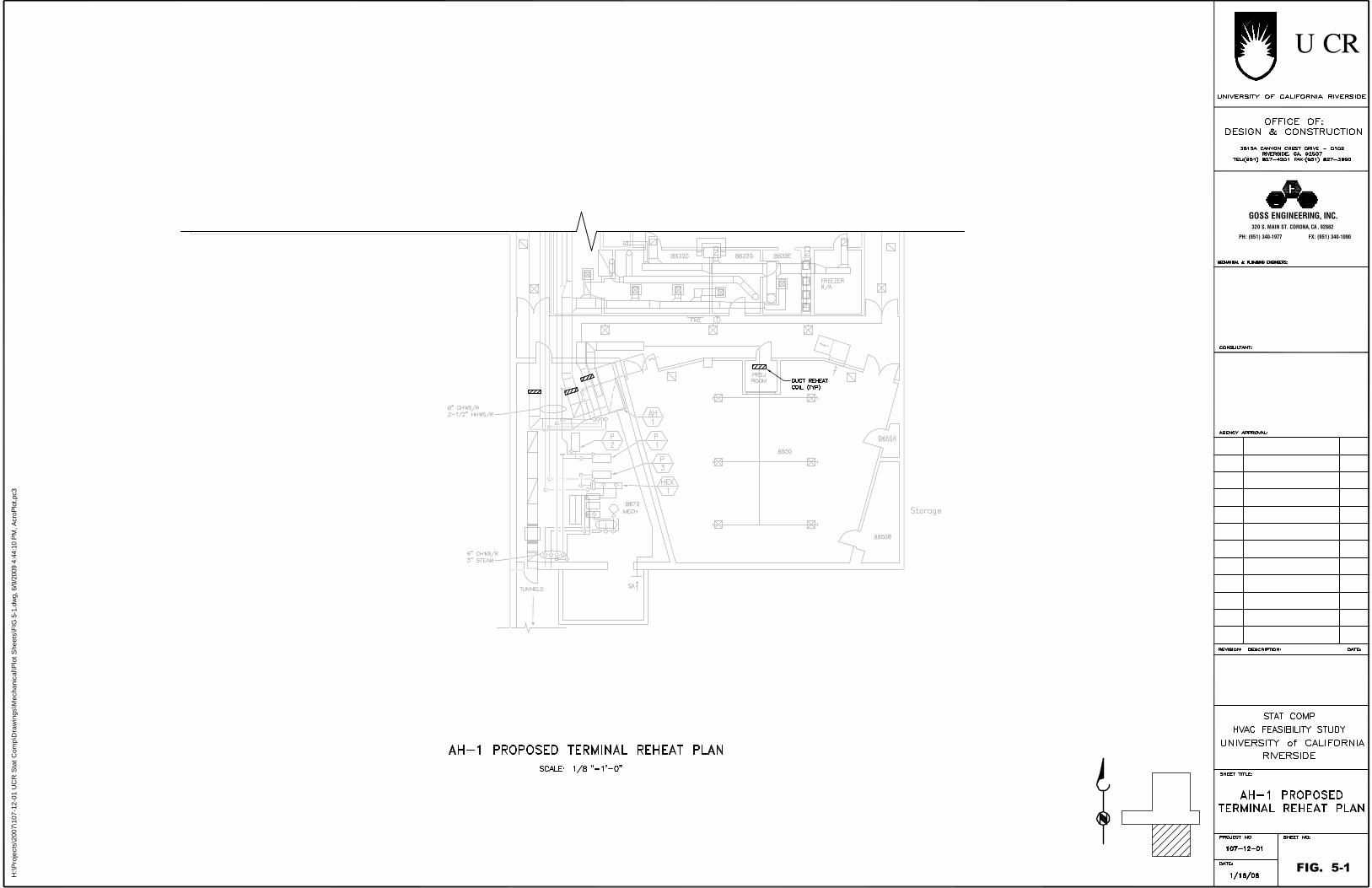
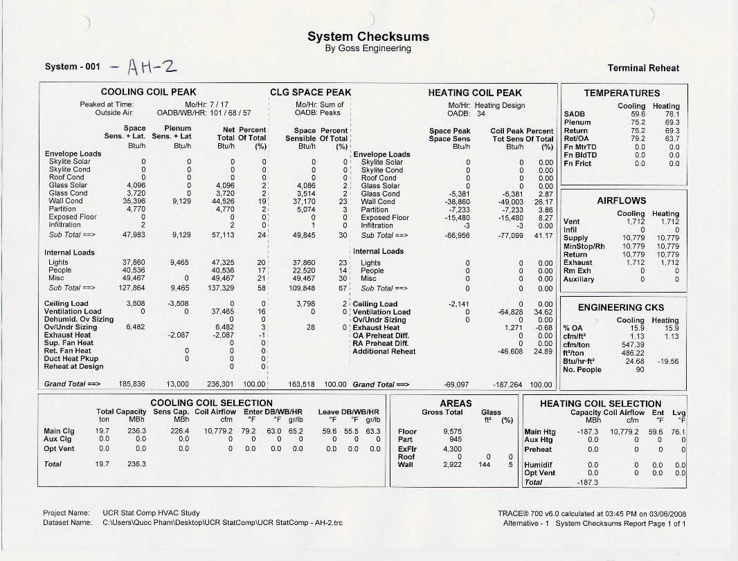
As shown in Figure 3-1 and Figure 3-2, AH-1 serves 3 temperature control zones,which include classroom, corridors and supporting areas for the Anatomy Lab in thebasement south. The unit is located in the Mechanical Room B670 shown on Figure 3-2.
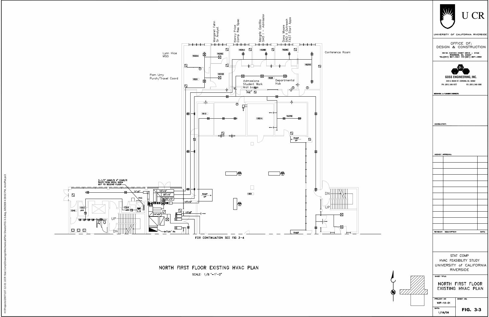
As shown in Figure 3-3, Figure 3-4, and Figure 3-5, AH-2 serves 9 temperaturecontrol zones, which includes offices, corridors and the server room on the first floor.The unit is located in the Mechanical Room 2590 on the second floor shown in Figure 3-5.
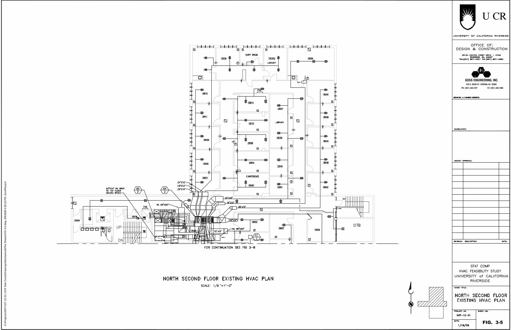
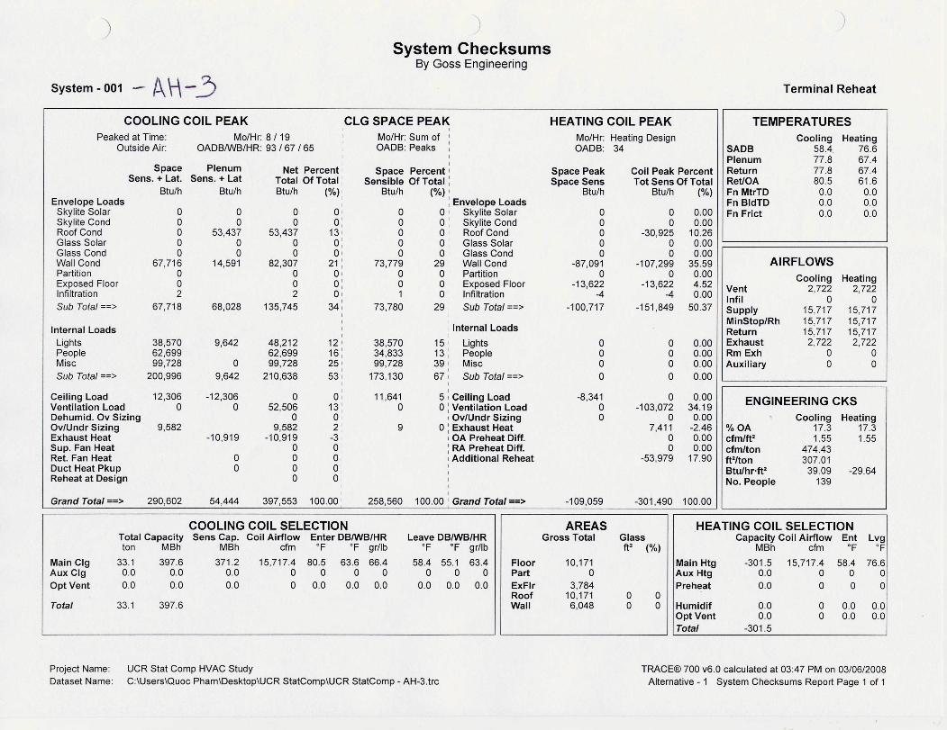
In Figure 3-5 and Figure 3-6, AH-3 serves 13 temperature control zones, whichincludes offices, computer labs, corridors and classrooms on the second floor. The unitis located in the Mechanical Room 2590 on second floor shown in Figure 3-5.
As shown in Figure 3-1, AH-4 serves 8 temperature control zones, which includes theoffice, exam rooms, corridors, Anatomy Lab, conference room and classroom on thebasement north. The unit is located in the Mechanical Room B625 in the basement.
AH-1, AH-2 and AH-3 were installed in mid 1970s when the building was constructed.AH-4 was installed in later the 1990s to replace the unit originally installed in mid the1970s.
Table 3-1 below summarizes the existing air-handling units. The airflows and staticpressures shown were obtained from available as-built information. As shown, the total

University of California, Riverside Statistics-Computer Building HVAC Study
Goss Engineering, Inc. DRAFT Page 3-2
building supply air was designed to be approximately 48,000 cfm. Detailed informationis presented in Table 3-2.
Table 3-1: Existing Air Handling Unit Summary
TagNo. Location Area Served
Design fanCapacity
(cfm @ in. w.g.TSP)
Motor HP OverallCondition
AH-1 Room B670 SouthBasement 7,800 @ 2.125 7.5 Poor
AH-2 Room 2590 First Floor 14,575 @ 2.375 15 Poor
AH-3 Room 2590 Second Floor 16,350 @ 2.125 20 Poor
AH-4 Room B625 NorthBasement 9,130 @ 2.5 7.5 Good
Table 3-2: Existing Air Handling Unit Detailed InformationAHU ID AH-1 AH-2 AH-3 AH-4
Area Served BASEMENTNORTH
FIRSTFLOOR
SECONDFLOOR
BASEMENTSOUTH
Make and Model MCQUAY MCQUAY MCQUAY HUNTAIR
TYPEBLOW-THRUMULTI-ZONE
BLOW-THRUMULTI-ZONE
BLOW-THRUMULTI-ZONE
BLOW-THRUMULTI-ZONE
Design SA CFM 7,800 14,575 16,350 9,130BLOWER TSP (IN
WC) 2.125 2.375 2.125 2.500
MOTOR HP 7.5 15 20 7.5OSA CFM 4,825 2,900 3,500 3,200RA CFM 2,975 11,675 12,850 4,730
ROW/FPI 8/8 8/8 8/8 5/8
CFM 7,070 13,225 15,250 7,800EAT
(DB/WB) 81.3/65.2 81.4/64.2 86/68.4 85/67
LAT(DB/WB) 53/51.8 53/51.2 53/51.8 55/54
TOTALMBH 270 476 616 310
APD(IN WC) 1.125 1.25 1.06 1.05
EWT (F) 43 43 43 44LWT (F) 54 57 59 54
GPM 49 68 77 62
COOLINGCOIL
WPD(FT WC) 3.9 10.5 8.4 10
University of California, Riverside Statistics-Computer Building HVAC Study
Goss Engineering, Inc. DRAFT Page 3-3
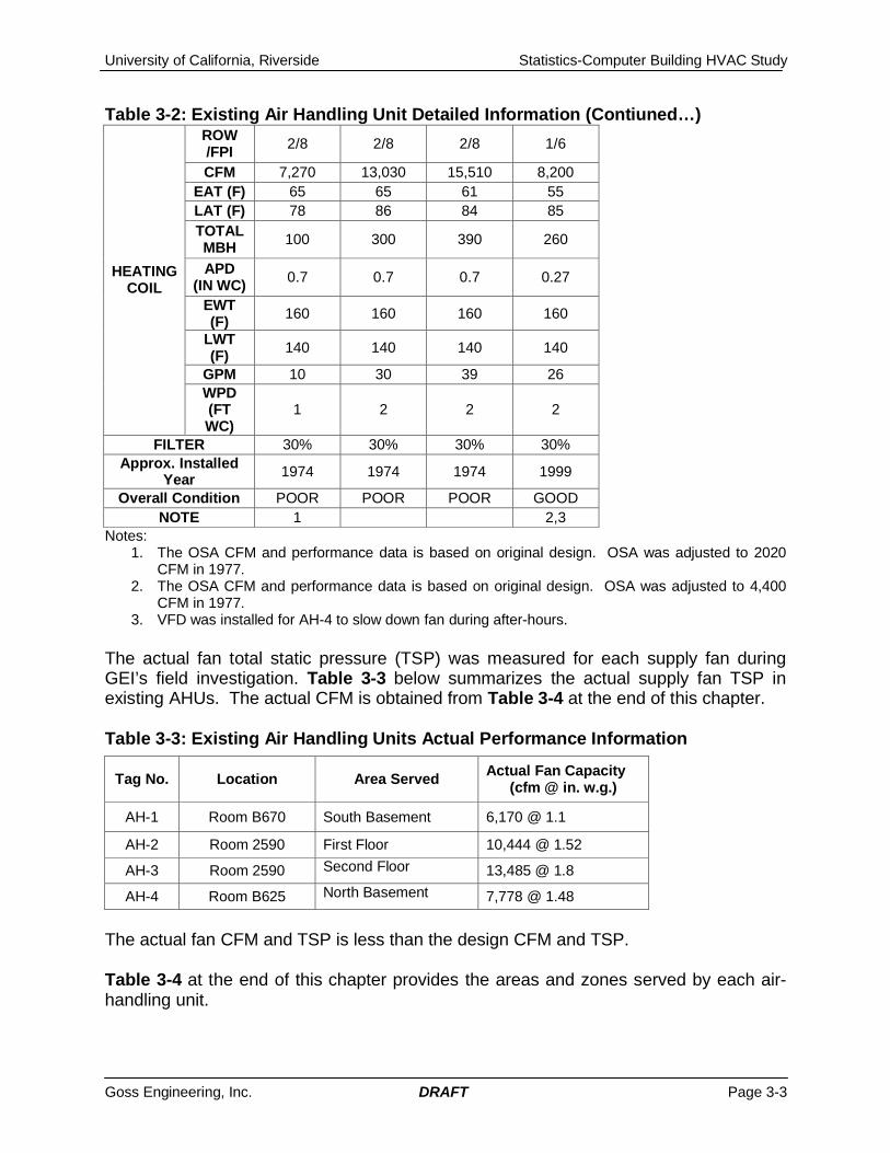
Table 3-2: Existing Air Handling Unit Detailed Information (Contiuned…)ROW/FPI 2/8 2/8 2/8 1/6
CFM 7,270 13,030 15,510 8,200EAT (F) 65 65 61 55LAT (F) 78 86 84 85TOTALMBH 100 300 390 260
APD(IN WC) 0.7 0.7 0.7 0.27
EWT(F) 160 160 160 160
LWT(F) 140 140 140 140
GPM 10 30 39 26
HEATINGCOIL
WPD(FTWC)
1 2 2 2
FILTER 30% 30% 30% 30%Approx. Installed
Year 1974 1974 1974 1999
Overall Condition POOR POOR POOR GOODNOTE 1 2,3
Notes:1. The OSA CFM and performance data is based on original design. OSA was adjusted to 2020
CFM in 1977.2. The OSA CFM and performance data is based on original design. OSA was adjusted to 4,400
CFM in 1977.3. VFD was installed for AH-4 to slow down fan during after-hours.
The actual fan total static pressure (TSP) was measured for each supply fan duringGEI’s field investigation. Table 3-3 below summarizes the actual supply fan TSP inexisting AHUs. The actual CFM is obtained from Table 3-4 at the end of this chapter.
Table 3-3: Existing Air Handling Units Actual Performance Information
The actual fan CFM and TSP is less than the design CFM and TSP.
Table 3-4 at the end of this chapter provides the areas and zones served by each air-handling unit.
Tag No. Location Area Served Actual Fan Capacity(cfm @ in. w.g.)
AH-1 Room B670 South Basement 6,170 @ 1.1
AH-2 Room 2590 First Floor 10,444 @ 1.52
AH-3 Room 2590 Second Floor 13,485 @ 1.8
AH-4 Room B625 North Basement 7,778 @ 1.48

University of California, Riverside Statistics-Computer Building HVAC Study
Goss Engineering, Inc. DRAFT Page 3-4
AHU Supply Fans
The supply fans are squirrel cage type, belt driven, forward curved, and double inletdual fans. For AH-1, AH-2, and AH-3, fan motors are mounted outside the unit while forAH-4, the motor is internal. The fans appear to be in poor condition. Figure 3-1 belowshows the old dusty dual squirrel cage fans in AH-2.
Figure 3-1: Existing Supply Fans in AH-2
The fact that the motors were mounted outside the air stream eliminates motor heatgains to the airflow, but increases air leakage through the fan shaft penetrations at theAHU casing.
Casing
The casing for AH-1, 2 and 3 appear to be in fair condition externally. However, theinternal casing liner appear to be peeled off and the downstream cooling coil internalcasing appears to be rusted. Some leakage were found through panel gaps and casingholes. The filters were installed upstream of the supply fans. Debris and dust insidethe AHUs were blown through the duct to the occupied areas.
Outside Air Intake
The outside air (OSA) is obtained through exterior wall louvers on the second floor forAH-2 and AH-3. For AH-4, OSA is obtained through the OSA wells, which are covered
University of California, Riverside Statistics-Computer Building HVAC Study
Goss Engineering, Inc. DRAFT Page 3-5
at the top with mesh grills, on grade level for AH-4. For AH-1, OSA is obtained from theexterior wall louvers at the basement level.
Coils
The heating and cooling cools appear to be in fair condition. The drain pans and coilframes are rotted allowing air to bypass the coil.
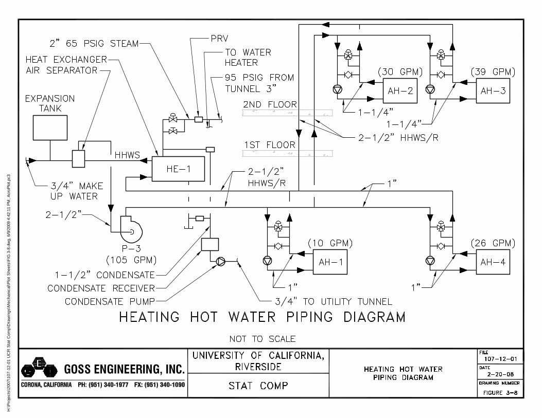
The cooling coils are served with chilled water (CHW) from the campus physical plant.The heating coils are served with building heating-hot-water (HHW) that is generated ina heat exchanger located in Room B670 with high pressure steam (~65 psig) from thecampus central plant.
Control Valves
The chilled and hot water control valves are three-way pneumatic control valves. Thevalves appear to be in fair condition at the time of GEI’s field investigation.
Zone Dampers
Multiple temperature zone mixing dampers were installed at each AHU hot and colddeck discharge. A thermostat located in the typical space within the zone modulates thedamper position (adjusts the cold deck and hot deck airflow ratio) to maintain spacetemperature. These zone dampers are pneumatic type and appear to be in faircondition.
Currently, 3 zone dampers were installed for AH-1, 9 zone dampers were installed forAH-2, 13 zone dampers were installed for AH-3, and 8 zone dampers were installed forAH-4.
Filters
The air handling units use 30% 2-inch thick throwaway filters.
Condition
Air-handling units AH-1, AH-2 and AH-3 are all now approximately 35 years old, and arein poor condition. As the expected median useful fan and coil service life is about 25years (2007 ASHRAE HVAC Applications, Table 4, page 36.3, Akalin 1978), the AHUhave exceeded their expected median service life by 10 years. The maintenancestaff should be commended for their efforts in keeping these units running for this long.
However, AH-4 was installed in the 1990s and appears to be in good condition.

University of California, Riverside Statistics-Computer Building HVAC Study
Goss Engineering, Inc. DRAFT Page 3-6
EXHAUST FANS
Three roof exhaust fans (EF) were installed to serve the building general and laboratoryexhaust. EF-1 serves restroom exhaust. EF-2 and EF-3 provides exhaust for theAnatomy Lab (Room B632) in basement. Table 3-5 below summarizes the existing roofexhaust fans.
Table 3-5: Existing Exhaust Fan Summary
Tag No. Location Area Served Capacity(cfm @ in wc)
MotorHP Type
EF-1 Roof General exhaust 3,175 CFM @0.5 0.75 Roof Exhauster
EF-2 Roof Anatomy Lab B632 3,800 CFM @ 1 1.5 Utility
EF-3 Roof Anatomy Lab B632 2,000 CFM @ 1 0.75 Utility
EXISTING AIRFLOW
Table 3-4 at the end of this chapter provides the design and actual supply, return, andexhaust air flows for each occupied space in the building.
The measured space supply air flow was typically less than the design air flow, as wellas the system outside air flow was more than the designed outside-air flow.
In a few cases the return air plenum has more pressure than the room causing reverseairflow.
DUCTWORK AND INSULATION
All the supply and return ducts are constructed with galvanized sheet metal. Ductsexposed in the mechanical room are internally insulated with duct liners. However, theducts in the concealed ceiling space is externally insulated with fiberglass blanket.Periodical duct cleaning is essential to keep the ductwork interior surfaces clean andsmooth to reduce debris from entering the occupied space and reduce air staticpressure loss and fan energy.
STEAM-TO-HHW HEAT EXCHANGER
High pressure steam at 60 psig is supplied to the building Mechanical Room B670 fromthe central plant through the underground tunnel. The steam-to-HHW (heating hotwater) heat exchanger was originally installed in mid 1970s. As the expected median

University of California, Riverside Statistics-Computer Building HVAC Study
Goss Engineering, Inc. DRAFT Page 3-7
useful heat exchanger service life is about 24 years (2007 ASHRAE HVAC Applications,Table 4, page 36.3, Akalin 1978), the original heat exchanger has exceeded itsexpected median service life by 10 years. Table 3-6 below shows the specificationsfor the heat exchanger.
Table 3-6: Heat Exchanger SpecificationsLocation Mechanical Room B670Type Shell and TubeManufacturer Bell & GossettModel No. SU 83-2HHW Flow (gpm) 80HHW Supply Temp (ºF) 180HHW Return Temp (ºF) 140Steam Pressure (psig) 65Steam Temperature (ºF) >300Service Building HeatingYear Installed 1974
PUMPS
The building has one HHW primary pump (P-3) and two chilled water (CHW) pumps (P-1 and P-2) in Room B670. The HHW primary pump circulates heating hot water in theprimary loop to the AHUs. A secondary pump installed at the AHU circulates the HHWthrough heating coils in the AHU.
The chilled water pump serves as a booster pump to circulate chilled water, from thephysical plant, to cooling coils in the AHUs. It appears that the two chilled water pumpswere installed later and appear to be good condition.
The heating hot water pump appears to be the original pump and is very old. All threepumps operate at constant speed to provide cooling and heating for the building.
Table 3-7 below provides a summary of the pumps.
University of California, Riverside Statistics-Computer Building HVAC Study
Goss Engineering, Inc. DRAFT Page 3-8
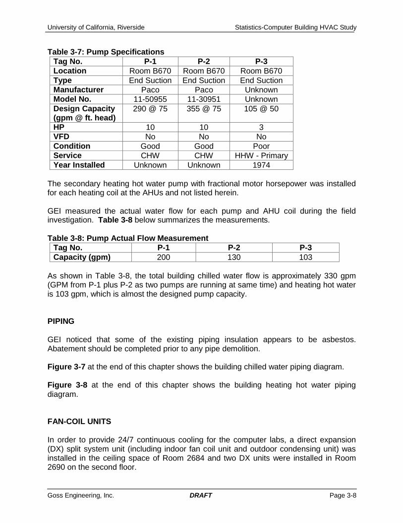
Table 3-7: Pump SpecificationsTag No. P-1 P-2 P-3Location Room B670 Room B670 Room B670Type End Suction End Suction End SuctionManufacturer Paco Paco UnknownModel No. 11-50955 11-30951 UnknownDesign Capacity(gpm @ ft. head)
290 @ 75 355 @ 75 105 @ 50
HP 10 10 3VFD No No NoCondition Good Good PoorService CHW CHW HHW - PrimaryYear Installed Unknown Unknown 1974
The secondary heating hot water pump with fractional motor horsepower was installedfor each heating coil at the AHUs and not listed herein.
GEI measured the actual water flow for each pump and AHU coil during the fieldinvestigation. Table 3-8 below summarizes the measurements.
Table 3-8: Pump Actual Flow MeasurementTag No. P-1 P-2 P-3Capacity (gpm) 200 130 103
As shown in Table 3-8, the total building chilled water flow is approximately 330 gpm(GPM from P-1 plus P-2 as two pumps are running at same time) and heating hot wateris 103 gpm, which is almost the designed pump capacity.
PIPING
GEI noticed that some of the existing piping insulation appears to be asbestos.Abatement should be completed prior to any pipe demolition.
Figure 3-7 at the end of this chapter shows the building chilled water piping diagram.
Figure 3-8 at the end of this chapter shows the building heating hot water pipingdiagram.
FAN-COIL UNITS
In order to provide 24/7 continuous cooling for the computer labs, a direct expansion(DX) split system unit (including indoor fan coil unit and outdoor condensing unit) wasinstalled in the ceiling space of Room 2684 and two DX units were installed in Room2690 on the second floor.

University of California, Riverside Statistics-Computer Building HVAC Study
Goss Engineering, Inc. DRAFT Page 3-9
Table 3-9 below summarizes the existing DX split systems.
Table 3-9: DX Split SystemTag No. FC-1/CU-1 FC-2/CU-2 FC-3/CU-3Location Ceiling/Roof Ceiling/Roof Ceiling/RoofType DX DX DXManufacturer Unknown Unknown UnknownModel No. Unknown Unknown UnknownCooling Tons 0.5 1.5 0.5Design CFM 200 550 200Condition Not working Not Working Not workingService Room 2690 Room 2684 Room 2684Year Installed 1980 1988 1980
These fan-units supplied no air to the room when the room temperature was as high as86 degree F during GEI’s field investigation. A huge ice block was found at the fan-coilunit above the ceiling as shown in Figure 3-9 below.
Figure 3-9: Ice block at Fan Coil Unit FCU-1 in Room 2690

University of California, Riverside Statistics-Computer Building HVAC Study
Goss Engineering, Inc. DRAFT Page 3-10
COMPUTER ROOM AIR CONDITIONING UNITS
Three computer room air conditioning (CRAC) units were installed to serve the ServerRoom 1601. All the units are bottom discharge and top return units. The room supplyair is discharged to the raised floor. Table 3-10 below provides the specifications of thethree CRAC units.
Table 3-10: Computer Room Air Conditioning UnitsTag No. CRAC-1 CRAC-2 CRAC-3Location Room 1601 Room 1601 Room 1601Type Chilled Water Chilled Water DXManufacturer DataAire DataAire DataAireModel No. DACD2631 DACD2631 DAAD2034Cooling Tons 26 26 20CFM 10,000 10,000 8,000Chilled Water Temp 45 - 55 45-55 -Chilled Water GPM 48 48 -Condition Fair Fair FairService Room 1601 Room 1601 Room 1601Year Installed Unknown Unknown Unknown
It appears that the room temperature is well controlled within the desired temperaturerange.
CONTROLS
The existing HVAC controls are stand-alone pneumatic controls. The controlmanufacturer for AH-1, 2 and 3 is unknown.
For AH-4, the pneumatic controls were provided by Johnson Controls. A variablefrequency drive (VFD) was installed for AH-4, which operates on a 24/7 schedule toprovide continuous ventilation for the areas including the Anatomy Lab. As an energysaving measure, the VFD slows down the fan to provide minimum required airflow whenthe building is unoccupied.
The existing temperature and pressure gauges are not operating correctly. Sometemperature gauges show inconsistent temperature readings and some pressuregauges show no pressure readings across the pump while the pump is running.

H:\P
roje
cts\
2007
\107
-12-
01 U
CR
Sta
t Com
p\D
raw
ings
\Mec
hani
cal\P
lot S
heet
s\FI
G 3
-1.d
wg,
6/9
/200
9 4:
38:4
6 PM
, Acr
oPlo
t.pc3
FIG. 3-1
320 S. MAIN ST. CORONA, CA , 92882
PH: (951) 340-1977 FX: (951) 340-1090
GOSS ENGINEERING, INC.

H:\P
roje
cts\
2007
\107
-12-
01 U
CR
Sta
t Com
p\D
raw
ings
\Mec
hani
cal\P
lot S
heet
s\FI
G 3
-2.d
wg,
6/9
/200
9 4:
38:5
4 PM
, Acr
oPlo
t.pc3
FIG. 3-2
320 S. MAIN ST. CORONA, CA , 92882
PH: (951) 340-1977 FX: (951) 340-1090
GOSS ENGINEERING, INC.
H:\P
roje
cts\
2007
\107
-12-
01 U
CR
Sta
t Com
p\D
raw
ings
\Mec
hani
cal\P
lot S
heet
s\FI
G 3
-3.d
wg,
6/9
/200
9 4:
39:0
2 PM
, Acr
oPlo
t.pc3
FIG. 3-3
320 S. MAIN ST. CORONA, CA , 92882
PH: (951) 340-1977 FX: (951) 340-1090
GOSS ENGINEERING, INC.

H:\P
roje
cts\
2007
\107
-12-
01 U
CR
Sta
t Com
p\D
raw
ings
\Mec
hani
cal\P
lot S
heet
s\FI
G 3
-4.d
wg,
6/9
/200
9 4:
39:1
0 PM
, Acr
oPlo
t.pc3
FIG. 3-4
320 S. MAIN ST. CORONA, CA , 92882
PH: (951) 340-1977 FX: (951) 340-1090
GOSS ENGINEERING, INC.
H:\P
roje
cts\
2007
\107
-12-
01 U
CR
Sta
t Com
p\D
raw
ings
\Mec
hani
cal\P
lot S
heet
s\FI
G 3
-5.d
wg,
6/9
/200
9 4:
39:1
8 PM
, Acr
oPlo
t.pc3
FIG. 3-5
320 S. MAIN ST. CORONA, CA , 92882
PH: (951) 340-1977 FX: (951) 340-1090
GOSS ENGINEERING, INC.

H:\P
roje
cts\
2007
\107
-12-
01 U
CR
Sta
t Com
p\D
raw
ings
\Mec
hani
cal\P
lot S
heet
s\FI
G 3
-6.d
wg,
6/9
/200
9 4:
39:2
7 PM
, Acr
oPlo
t.pc3
FIG. 3-6
320 S. MAIN ST. CORONA, CA , 92882
PH: (951) 340-1977 FX: (951) 340-1090
GOSS ENGINEERING, INC.

H:\P
roje
cts\
2007
\107
-12-
01 U
CR
Sta
t Com
p\D
raw
ings
\Mec
hani
cal\P
lot S
heet
s\FI
G 3
-7.d
wg,
6/9
/200
9 4:
42:0
4 PM
, Acr
oPlo
t.pc3
GOSS ENGINEERING, INC.
H:\P
roje
cts\
2007
\107
-12-
01 U
CR
Sta
t Com
p\D
raw
ings
\Mec
hani
cal\P
lot S
heet
s\FI
G 3
-8.d
wg,
6/9
/200
9 4:
42:1
1 PM
, Acr
oPlo
t.pc3
GOSS ENGINEERING, INC.
University of California, Riverside Statistics-Computer Building HVAC Study
Goss Engineering, Inc. DRAFT Page 4-1
CHAPTER 4
HVAC SYSTEM ANALYSIS
This chapter analyzes the existing HVAC system, including room air flows, existingductwork, and existing piping. The existing system analysis identifies the problems withthe existing HVAC system. The existing HVAC system is described in Chapter 3.
SYSTEM AIRFLOW
This paragraph presents the existing HVAC system airflow comparison with thedesigned, required (or calculated) and actual airflow.
Required HVAC System Air Flow
The required airflow for the existing system is determined by the required systemcooling and heating load. The HVAC cooling and heating load for a typical system isdetermined by the heat gains through the space enclosure such as walls, windows, roof,as well as occupants, outside air ventilation, lighting, and equipment (i.e. computers,etc).
California Title-24 climate zone for the City of Riverside is 10. The weather is hot in thesummer and mild in the winter. Per California Title-24, the 0.1% summer designoutdoor temperature used for a critical facility (such as AH-1 and AH-4 serving labs) is110 degrees F dry-bulb and coincident 75 degrees F wet-bulb, and 0.5% summerdesign outdoor temperature for non-critical facility (such as AH-2 and AH-3 systems) is104 degree F dry-bulb and coincident 69 degree F wet-bulb. For both facilities, thewinter minimum temperature is 34 degrees F.
In addition to the temperatures described above, the following criteria, based ongoverning code requirements (for occupancy, ventilation, temperature, etc), equipmentnameplate data (computers, etc), and industry-wide used defaults (when actual load isnot available), were used as a basis for each system load calculation:
Ventilation: 20 cfm per person or 0.15 cfm per square foot of gross floor area,whichever is larger.
Lighting load: 1.5 watts per square foot for offices. Occupant number: counting seats or averaged 100 square feet per person,
whichever is larger. 250 btu per hour for sensible and latent heat gainrespectively.
Equipment (computer, printer, and etc) heat gain: counting computer quantity or2 watts per square foot of enclosed space floor area, whichever is larger.
Design indoor temperature: summer 75 F and winter 70 F for typical officeareas; 72 F for typical computer labs in both summer and winter.

University of California, Riverside Statistics-Computer Building HVAC Study
Goss Engineering, Inc. DRAFT Page 4-2
SA temperature at 55 F is used for CFM calculations.
GEI used the Trane Trace 700 load calculation software for this study to estimate thebuilding HVAC system cooling and heating load requirements. The following buildingenclosure information, based on GEI’s field investigation and as-built drawings, wasused for system load calculations:
4.5-inch thick concrete roof with R11 rigid insulation 10-inch thick brick exterior wall without insulation Uninsulated clear window without shading– 1.1 btuh/sqft per degree F for “U”
factor, 0.8 for shading coefficient (SC).
Table 4-1 below summarizes the HVAC system/space cooling load calculation output.Detailed calculation outputs are provided in Appendix A at the end of this report.
Table 4-1: HVAC System Air Flow and Water Flow Calculated Requirement
Airflow Comparison
Due to lack of the HVAC system air balancing report, in early January 2008, GEImeasured the actual supply airflow rate to the all the spaces by using a digital flowhood. The flow hood has a +/- 3% accuracy. Table 3-4 in chapter 3 summarizes andcompares the measured supply airflow rate to the rooms versus the design flow rate.Table 4-2 below presents the calculated, designed and actual system airflowcomparison. All the calculated airflow rates were based on the 55 degree F supply airtemperature.
Table 4-2: HVAC System Air Flow Comparison
Tag No. Location Area ServedRequired CFM @55 F supply airtemp
Required ChilledWater GPM @ 15 Fdelta-T
AH-1 Room B670 South Basement 6,840 45
AH-2 Room 2590 First Floor 10,780 32
AH-3 Room 2590 Second Floor 15,710 53
AH-4 Room B625 North Basement 8,788 31
Tag No. Location Actual CFMRequired CFM @55 F supply airtemp
Design CFM
AH-1 Room B670 6,170 6,840 7,800
AH-2 Room 2590 10,444 10,780 14,575
AH-3 Room 2590 13,485 15,710 16,350
AH-4 Room B625 7,778 8,788 9,130

University of California, Riverside Statistics-Computer Building HVAC Study
Goss Engineering, Inc. DRAFT Page 4-3
As shown in Table 4-2, except for AH-2, the actual supply air rates from other systemare 10 to 20 percent less than the calculated rates. For AH-2, the actual CFM is withinthe 5% range and appears to be reasonable.
PIPING SYSTEM
The Statistics-Computer Building is served by 6-inch chilled water supply and returnpipes from the Central Plant. The calculated total chilled water required is 161 gpm forthe four AHUs, based on supply/return at 45/60 degree F, shown in Table 4-1. Theactual total pump capacity is approximately 330 gpm for chilled water (including CRACunit 96 gpm total) and 103 gpm for heating hot water. The existing chilled water andheating hot water pumps and piping are adequate to serve the load.
THERMAL CHALLENGES ANALYSIS
GEI believes that the following factors listed below are the cause of the building thermaldiscomfort issues:
Existing HVAC system lowered cooling and heating capacity than design. Lack of air balancing and duct cleaning. Improper return-air path Excessive outside air Existing old and less responsive pneumatic controls Failed DX split system Improper zoning and locations of thermostats
The above items are described below.
Existing HVAC System Lowered Cooling and Heating Capacity than Design. Theexisting coils in AH-1, AH-2 and AH-3 are very old and have less heat transfercapacities than as designed. During the summer and winter, the coil leaving airtemperature set point is difficult to maintain. Also, AH-1, AH-3 and AH-4 deliver lessthan required airflow to the occupied space. Therefore, the space temperature cannotbe maintained at design ranges.
Lack of Air Balancing and Duct Cleaning Although the current total airflow supply tothe spaces are adequate for system AH-2, the existing supply air was not properlybalanced for each individual occupied space. Some rooms have more supply air thanneeded while other rooms have less supply air than needed. Some room function hasbeen changed while the supply air had never been re-balanced to meet the new loadrequirement. As a result, thermal discomfort problem occurs in these rooms.

University of California, Riverside Statistics-Computer Building HVAC Study
Goss Engineering, Inc. DRAFT Page 4-4
Also, it appears that the existing duct system was never cleaned. The duct systemswere installed more than 30 years ago. Dust and debris build-up creates extra airpressure drop (resistance) along the ductwork and reduces the supply air flow.
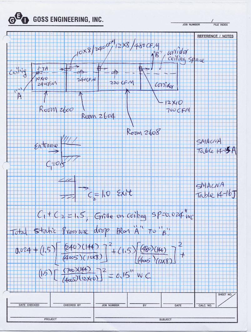
Improper Return-Air Path Existing return corridor ceiling space is used as a return airplenum. Return air was designed to be transferred through ductwork from one room tothe ceiling space of the adjacent room, and then transferred to the corridor ceiling spacethrough a fire damper protected corridor wall. Some return air is transferred more than3 times in series from room to room. For example, return air is designed to betransferred from Room 2066 through ceiling the grille to its ceiling space, then in seriesto the ceiling space of Room 2604 and 2608 then through the fire damper-protectedopening to the corridor ceiling space.
While the existing return-air paths to the plenum seems to be operable at first glance,the actual existing RA path of travel has a very high static pressure (SP) required tomove air from Room 2600 to 2604 to 2608 then to the corridor ceiling space iscalculated and shown in Appendix B. As indicated, a minimum SP is 0.15-in watercolumn (W.C.). The plenum cannot be maintained at such a negative pressure (the T-bar ceiling is not sealed air tight) and therefore, the air is never completely returnedfollowing the existing RA paths. Instead, only a small part of the room air is returned tothe system, resulting in room over-pressurization. On the other hand, the return air tothe AHU includes space return air and outside air.
Excessive Outside Air The existing system has excessive OSA due to minimum returnair and lack of system air balancing. Too much OSA increases the coil heating andcooling load causing the coil leaving-air-temperature to be difficult to control within thepreset range.
Existing Old and Less Responsive Pneumatic Controls The existing controls are allout dated pneumatic controls and less responsive. The space mounted thermostatmodulates the zone damper at the unit discharge through a pneumatic signal to controlroom temperature. It takes a while to communicate between the damper and thethermostat. Therefore, the space temperature is nearly impossible to control within therequired range unless the space load is relatively stable.
Failed DX Split Systems Three direct expansion split systems currently serving Room2686 and 2690 (computer labs) are not working properly. These units are in very badcondition and appear to be in already-failed condition. The dedicated space temperaturesensors (not the wall mounted pneumatic thermostats which control zone dampers),which are installed in the house-air ceiling return grilles, fail to energize the split systemfor cooling causing the room temperature to reach as high as 85 degree F.
Improper Zoning and Locations of Thermostats Some temperature control zonesinclude many spaces have only one thermostat in one of the rooms. Due to the variouscooling and heating load profiles among these rooms, the temperature of the room withthe thermostat is under control while the other rooms, with different load profiles,
University of California, Riverside Statistics-Computer Building HVAC Study
Goss Engineering, Inc. DRAFT Page 4-5
experience thermal discomfort. For example, Room 1626A, 1626B, 1626C (3 offices)share a zone with Room 1626D (conference room). Room 1626D is a conference roomwith a different cooling load profile than basic office areas.
University of California, Riverside Statistics-Computer Building HVAC Study
Goss Engineering, Inc. DRAFT Page 5-1
CHAPTER 5
PROPOSED HVAC SYSTEM MODIFICATIONS
This chapter discusses the proposed HVAC system modifications to resolve the currentthermal discomfort issues in the building.
PROPOSED HVAC SYSTEM MODIFICATIONS
As discussed in Chapter 4, the existing HVAC system is experiencing inadequatecooling and heating, out dated controls, lack of balancing, excessive OSA, and spaceover-pressurization. GEI proposed the following modifications to resolve the currentthermal discomfort issues:
Replace existing heating and cooling coils and supply fans with larger capacity inAH-1, AH-2 and AH-3
Rebalance OSA, RA and SA to meet room loads Completely clean existing ductwork Eliminate RA transfer paths and install fire-ceiling RA plenum or return duct Replace existing controls with direct digital controls (DDC) Replace Failed DX split systems with new
The following paragraphs describe the modifications in more details.
Replace Existing Heating and Cooling Coils and Supply Fans with LargerCapacity in AH-1, AH-2 and AH-3
As discussed in Chapter 4, the existing fans and coils are very old, have lower capacity,and should be replaced with new. GEI proposed three options for this modification.
Option 1 - Replace existing coils and fans only with new. New fans areproposed to be more energy efficient and have larger airflow capacity. The fanmotors are proposed to be installed inside the air handling units to prevent airleakage through fan shaft penetrations. With new cooling and heating coils, theheat transfer will be improved and the coil leaving air temperature can bemaintained at the desired range. As the existing unit casings are very old andleaking air, GEI does not recommend this option. This option is presentedhere is to show this as a basis for option comparison purposes.
Option 2 - Replace Existing AHUs with new. As described in Chapter 3, theexisting casings have air leakage and interior casing liners are peeled off. Newcustom-made field-built-up AHUs are proposed to have double wall constructionwith perforated metal liner instead of existing fiberglass liners. Compared with
University of California, Riverside Statistics-Computer Building HVAC Study
Goss Engineering, Inc. DRAFT Page 5-2
option 1, this option includes the replacement of the entire unit and therefore costmore than option 1. However, the advantages includes more energy savings dueto less or no air leakage and better casing insulation.
Option 3 - Replace Existing AH-1, AH-2 and AH-3 with New Cooling OnlyUnits and Install Terminal Zone Reheat Coils. The supply air temperature isproposed to be maintained at 55 degree F prior to the terminal heating hot waterreheat coils. The space thermostat then modulates the reheat coil control valveto maintain the space temperature. Compared with option 2, this option havethe following advantages:
1. Zoning flexibility. It is impossible to add new duct zones to the existingAH system if more zones are added. However, with reheat coil optionand some ductwork modifications, additional zones can be added tothe existing ductwork. This is best suited for the future room functionchanges or current zoning addition.
2. Better temperature controls. Space thermostats modulate the reheatcoil valves to control room temperature. Temperature controls aremore responsive.
The disadvantages are high construction cost. AH-4 is in good condition and isnot proposed to be replaced.
GEI recommends Option 3.
Figure 5-1shows the proposed AH-1 system floor plan.
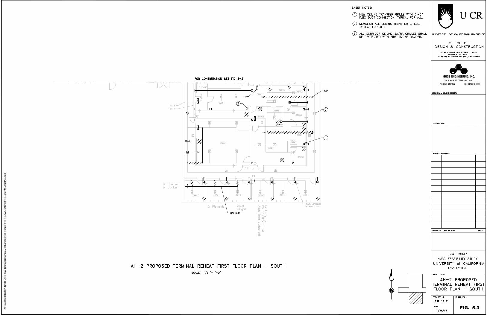
Figure 5-2 and Figure 5-3 show the proposed AH-2 system floor plan.
Figure 5-4 and Figure 5-5 show the proposed AH-3 system floor plan.
Rebalance OSA and SA to Meet Room Load
The existing building OSA and supply air to the occupied spaces is not properlybalanced as described in Chapter 4. The space supply air should be rebalanced tomeet the space load requirements. The building OSA should be reset to the minimumrequirements set by the 2007 California Mechanical Code and Title-24.
Completely Clean Existing Ductwork
The existing building supply and return duct and diffusers should be completelycleaned.

University of California, Riverside Statistics-Computer Building HVAC Study
Goss Engineering, Inc. DRAFT Page 5-3
Eliminate RA Transfer Paths and Install Fire-Ceiling RA Plenum or Return Duct
The existing return air transfer duct is proposed to be removed to eliminate thereturn/transfer air paths. Two options were developed to provide the required air return.
Option 1 – Install new 2-hour fire-rated ceiling on the first and second floorcorridor areas. The existing corridor walls are full height fire-rated wall. Thecorridor ceiling is a typical non-rated T-bar ceiling. The corridor ceiling spacecurrently serves as a return-air plenum. The existing return-air enters the plenumthrough the corridor wall openings protected with fire dampers. GEI proposes a2-hour rated hard ceiling installed in the corridor to make the corridor a fire exittunnel. The corridor ceiling space can be used as a return air plenum. Theopenings on the corridor walls do not require fire protection. Each room canhave a direct opening to the ceiling return plenum instead of passing through areturn/transfer air path. By eliminating the paths, building pressurization andOSA leakage problems may be resolved.
There is no need for a 2-hour fire-rated ceiling for the area served by AH-1 andAH-4 in the basement.
Figure 5-2 and 5-3 shows proposed first floor plan. Figure 5-4 and 5-5 showsproposed second floor plan.
Option 2 – Install new return duct to each space To remove the transfer airpaths, return air ducts to each room can be installed. However, the very limitedexisting corridor ceiling space (approximately 18 inches between bottom ofstructure and ceiling), existing ceiling supply ducts, electrical conduits and pipesmakes the new duct installation very difficult and virtually impossible. Figure 5-6shows first floor plan. Figure 5-7 shows second floor plan. GEI does notrecommend this option.
Replace Existing Controls with Direct Digital Controls (DDC)
The existing pneumatic controls are too old and out dated. GEI proposed to replace theexisting controls with new DDC controls. The DDC is very responsive and easy tomonitor and adjust.
Replace Failed DX Split Systems with New Chilled Water Fan Coil Units
The existing three DX split systems are not working properly. GEI proposed to replacethe three units with new chilled water units with the cooling capacity to meet the currentload. When larger delta-T cooling coils are installed to replace the existing coils in theAHUs, less chilled waterflow (in gpm) is required and therefore, existing pipe size isadequate.
Figure 5-4 and Figure 5-5 show chilled water unit locations and piping routes.
H:\P
roje
cts\
2007
\107
-12-
01 U
CR
Sta
t Com
p\D
raw
ings
\Mec
hani
cal\P
lot S
heet
s\FI
G 5
-1.d
wg,
6/9
/200
9 4:
44:1
0 PM
, Acr
oPlo
t.pc3
FIG. 5-1
320 S. MAIN ST. CORONA, CA , 92882
PH: (951) 340-1977 FX: (951) 340-1090
GOSS ENGINEERING, INC.

H:\P
roje
cts\
2007
\107
-12-
01 U
CR
Sta
t Com
p\D
raw
ings
\Mec
hani
cal\P
lot S
heet
s\FI
G 5
-2.d
wg,
6/9
/200
9 4:
44:1
7 PM
, Acr
oPlo
t.pc3
FIG. 5-2
320 S. MAIN ST. CORONA, CA , 92882
PH: (951) 340-1977 FX: (951) 340-1090
GOSS ENGINEERING, INC.
H:\P
roje
cts\
2007
\107
-12-
01 U
CR
Sta
t Com
p\D
raw
ings
\Mec
hani
cal\P
lot S
heet
s\FI
G 5
-3.d
wg,
6/9
/200
9 4:
44:2
5 PM
, Acr
oPlo
t.pc3
FIG. 5-3
320 S. MAIN ST. CORONA, CA , 92882
PH: (951) 340-1977 FX: (951) 340-1090
GOSS ENGINEERING, INC.

H:\P
roje
cts\
2007
\107
-12-
01 U
CR
Sta
t Com
p\D
raw
ings
\Mec
hani
cal\P
lot S
heet
s\FI
G 5
-4.d
wg,
6/9
/200
9 4:
44:3
3 PM
, Acr
oPlo
t.pc3
FIG. 5-4
320 S. MAIN ST. CORONA, CA , 92882
PH: (951) 340-1977 FX: (951) 340-1090
GOSS ENGINEERING, INC.

H:\P
roje
cts\
2007
\107
-12-
01 U
CR
Sta
t Com
p\D
raw
ings
\Mec
hani
cal\P
lot S
heet
s\FI
G 5
-5.d
wg,
6/9
/200
9 4:
44:4
2 PM
, Acr
oPlo
t.pc3
FIG. 5-5
320 S. MAIN ST. CORONA, CA , 92882
PH: (951) 340-1977 FX: (951) 340-1090
GOSS ENGINEERING, INC.

University of California, Riverside Statistics-Computer Building HVAC Study
Goss Engineering, Inc. DRAFT Page 6-1
CHAPTER 6
OTHER FINDINGS AND PROPOSED MODIFICATIONS
This chapter discusses other findings related to potential energy conservation duringGEI’s field investigation and proposed modifications for energy savings.
CHILLED WATER 3-WAY CONTROL VALVES
The existing 4” chilled water control valves (one for each AHU) are all 3-way mixingcontrol valves. The two chilled water pumps are running at constant speed to supplychilled water. The 3-way chilled water control valves should be avoided. Thedisadvantages for the 3-way valves are as follows:
Constant speed pumps (each with 10 hp motor) consumes a constant amount ofenergy even at partial load which occur most of time.
The mixing valves decrease the chilled water return temperature at partial load.The higher chilled water return temperature is, the more efficient the thermalstorage tank in the Physical Plant would be.
LOW CHILLED AND HEATING HOT WATER TEMPERATURE DIFFERENTIAL
The existing design chilled and heating hot water temperature difference appears to bevery low. The chilled water temperature difference was designed to be ranging from 10to 16 degree F and the heating hot water temperature difference was designed to beapproximately 20 degree F. Lower temperature differential across coils results in largerpumps, motors and pipes.
HEATING HOT WATER PIPING
The existing HHW piping system is a primary-secondary system. The primary pump P-3 is always running at constant speed to supply water to the AHUs. A secondary smallpump is installed at the AHU to circulate HHW to heating coil when heating is required.As the HHW is generated by a steam-to-water heat exchanger (not a boiler whichrequires minimum 120 degree F return water temperature to avoid condensation), aconstant water flow in the loop is unnecessary and wasting energy.
ECONOMIZER
The existing HVAC system has a constant return and outside air system. No modulatingdampers (economizer) were installed in the return and outside air duct. When outside

University of California, Riverside Statistics-Computer Building HVAC Study
Goss Engineering, Inc. DRAFT Page 6-1
temperature is between 55 and 75 degree F, the space air (usually more than 75degree F in summer) is still returned to the AHUs and wasting chiller energy.
RECOMMENDATIONS
GEI recommended the following modification for energy conservations:
Replace existing 3-way valves with new 2-way valves Install variable frequency drives (VFD) on the chilled and heating hot water
primary pumps. At partial load, the 2-way control valves close and water flow isreduced. The VFDs then slow down the chilled and heating hot water pumpsand energy is saved.
Remove all secondary heating hot water pumps. Install economizers for all air handling units. Install roof exhaust fans to relieve
building pressure during economizer cycles Select cooling and heating coils with large temperature differential. Use
minimum of 20 degree F temperature differential for the chilled water coils toimprove thermal storage efficiency and reduce pump energy consumption.Minimum of 60 degree F temperature differential should be used for heating coilselections. Compared to existing 20-degree F, the pump energy is reduced by atleast 65%.

University of California, Riverside Statistics-Computer Building HVAC Study
Goss Engineering, Inc. DRAFT Page 7-1
CHAPTER 7
BUDGET CONSTRUCTION COST ESTIMATE
This chapter describes the estimated budget construction cost for the proposed HVACmodifications options described in Chapter 5.
BUDGET CONSTRUCTION COSTS
The estimated budget construction costs for the Statistics-Computer Building HVACModifications include the following work:
Mechanical Work. In general the mechanical work includes the demolition andinstallation of the existing equipment and ductwork.
Electrical Work. All work associated with conveying electrical power to the newequipment.
Structural Work. All structural work associated with supporting new equipment.
In addition to the direct costs associated with the above-mentioned work theconstruction costs include the following:
7.75% sales tax on the cost of all materials. 5% General Requirements on the total direct construction cost, including sales
tax. 20% contingency on the total direct construction cost, including sales tax and
General Requirements. 15% of construction cost (direct construction cost, sales tax, General
Requirements, contingency, midpoint escalation, and insurance and bond) forcontractor’s overhead and profit.
Table 7-1 at the end of the chapter provides a detailed budget construction costestimate for Option 2 – Replace existing AH-1, AH-2 and AH-3 with new.
Table 7-2 at the end of the chapter provides a detailed budget construction costestimate for Option 3 – Replace existing AH-1, AH-2 and AH-3 with new cooling onlyunits and terminal reheat coils.
The estimated total budget construction cost estimate for Option 2 is approximately$930,000.
The estimated total budget construction cost estimate for Option 3 is approximately$1,100,000.

University of California, Riverside Statistics-Computer Building HVAC Study
Goss Engineering, Inc. DRAFT Page 7-2
GEI recommends adding 20% of the construction cost for engineering (10%),construction admin (5%), owner construction contingency (4%), and testing (1%) tocover project costs.

APPENDIX A
Load Calculations


APPENDIX B
Transfer Duct Path Static Pressure Calculations