status of the alma antenna production · the messenger 130 – december 2007 15 status of the alma...
TRANSCRIPT

15The Messenger 130 – December 2007
Status of the ALMA Antenna Production
Stefano Stanghellini (ESO)
The design of the ALMA antennas began in 1999 with a prototyping phase. Two antenna prototypes were built, extensively tested at the VLA site in New Mexico and evaluated in 2003. It was decided to proceed to procurement with two parallel calls for tenders based on the two prototypes. In 2005 contracts were placed with the US VertexRSI and the European AEM Consortium for 25 antennas each. An update on the two designs and the production progress is presented. The Japanese antennas (both 7 and 12 m) are being built by Mitsubishi, which also built an additional antenna prototype. The first antennas have re cently arrived at the integration facility at the ALMA Operations Support Facility (OSF).
As reported in previous editions of The Messenger (e.g. Haupt and Rykaczewski, The Messenger, 128, 25, 2007), the ALMA observatory will be equipped with fifty-four 12-m dish antennas and twelve 7-m dish antennas. Of the 12-m antennas, 25 will be provided by North America through Associated Universities Incorpo-rated (AUI) and 25 will be provided by Europe through ESO. Four 12-m antennas, as well as all the 7-m antennas, will be provided by Japan through the National Astronomical Observatory of Japan (NAOJ). The process leading to the pro-curement of the antennas started in 1999 when the decision was taken to prove the feasibility of the science-driven antenna specifications by prototyping. This occurred shortly after Europe and the U.S., until that time pursuing separately the Large Southern Array (LSA) and the Millimiter Array (MMA) respectively, had signed a formal agreement on collabora-tion for the development phase of ALMA. The National Radio Astronomy Observa-tory (NRAO), operated by AUI under a cooperative agreement with the National Science Foundation, and ESO initiated therefore the procurement of two antenna prototypes, to be installed at the Very Large Array (VLA) premises of the NRAO in New Mexico. It was decided that these two prototypes would be evaluated on an agreed test programme by a joint team of experts, the Antenna Evaluation
Group (AEG). The National Astronomical Observ atory of Japan (NAOJ) engaged in a pro ject of this kind, the Large Millimetre and Submillimitre Array (LMSA), also decided to procure a 12-m antenna pro-totype and to test it at the VLA.
Procurement strategy and contracting process
Originally it was envisaged to use the blueprints of one prototype antenna for the serial production, if one of the two de signs had been found superior to the other. However, the testing of key perfor-mance of these prototype antennas proved to be harder than anticipated, due to the intrinsic limitations at the VLA site and the incomplete debugging of anten-nas and evaluation equipment (receivers, holography systems, subreflector nutator, optical pointing telescopes), so no clear conclusion could be reached in the antic-ipated time frame.
To avoid a delay of the project by awaiting the final results of the prototype evalu-ation, parallel calls for tender to industry were issued in December 2003 by AUI and ESO for the supply of the serial antennas based on revised antenna func-tional specification. The call for tender was not restricted to a particular design and information on the design of the two prototypes was included as background information to potential industrial bidders. In May 2004 the bids were opened and the evaluation and discussions with the bidders started. The bidders based their proposals on the design of the prototypes. Therefore further test campaigns were launched to integrate the data and the preliminary conclusions were collected by the Antenna Evaluation Group. The tests of the prototypes, performed by panels of specialists including ESO personnel, involved verification methods different from those adopted by the AEG (photo-grammetry, quadrant detector, out of focus measurements) and included 100 000 cycles of fast switching to stress-test the antenna and the primary reflec-tors. The tests were concluded in April 2005, with the final conclusion that anten-nas based on both prototype designs
are expected to be able to fulfil the ALMA specification. This result brought a cam-paign of tests, spanning over two years, to its end. Testing these state-of-the-art antennas had involved a great deal of effort from the persons involved in pre-paring the test equipment, those collect-ing the data and finally, from the various groups interpreting the data with analysis and simulation.
Shortly after the completion of the tests, in July 2005, AUI concluded negotiations with VertexRSI, a subsidiary of General Dynamics, and signed a contract for the supply of up to 25 antennas with options for up to 32 antennas. ESO followed in December 2005 with the signature of the contract for 25 antennas, also with options for up to 32 antennas, with the AEM Consortium (Alcatel Alenia Space, European Industrial Engineering and MT-Aerospace1). These two contracts are to date the largest contracts for ground-based astronomy projects.
Both contracts, based on identical tech-nical specification and statement of work, foresee an initial design phase terminated by a design review. The design phase allows the antenna vendors to incorpo-rate in the design of the serial antennas modifications demanded by the new ALMA specification, and, equally impor-tant, improvements consequent on the findings discovered during testing and operating the antennas. The vendors are asked to perform qualification activities in the technological areas sensibly differ-ing from those validated on the prototype antennas.
In a separate process NAOJ ordered four 12-m antennas from Mitsubishi Electric Corporation on the basis of an almost identical specification to that of the bilat-eral project. Minor differences are related to the fact that the four Japanese anten-nas will perform total power measurement and are equipped with individual nutating subreflectors.
1 After signature of the contract Alcatel Alenia Space was absorbed by Thales to form the company Thales Alenia. Similarly the obligations of MT-Aero-space have been transferred to MT Mechatronics.
Telescopes and Instrumentation

16 The Messenger 130 – December 2007
Telescopes and Instrumentation
Design update
The ALMA antenna team, consisting of members of the three organisations, have conveyed to the manufacturers the expe-rience accumulated in at least two years of testing and operation. This precious experience extended well beyond the assessment of the science-related pefor-mance of the antennas: much more it was related to the reliability and the main-tainability aspects of the designs, rec-ognised to be of fundamental importance for the efficient and economical operation of a large array at 5 000 m altitude. Each design modification required by ALMA, or proposed by the Contractors, was re -viewed in depth during the design phase. For all three serial antennas the design phase was terminated by formal Pre- Production Design Reviews (PPDR) which saw the participation of a large reviewer group beyond the antenna team staff. The respective PPDRs for the three sup-pliers were held between November 2005 and February 2007.
The design of the North American anten-na was jointly performed by Vertex Anten-nentechnik (VA) in Duisburg, Germany, and VertexRSI in Kilgore, Texas. VA is also the designer of the APEX Telescope. The Vertex antenna is equipped with a rim pinion drive system with double motors on both axes and a control sys-tem based on absolute encoders. The Carbon Fibre Reinforced Plastic (CFRP) Backup Structure (BUS) is joined to a steel cabin by means of a large Invar support cone. This cone decouples the effect of thermal expansion of the steel cabin from the thermally stable BUS, which is manufactured from CFRP. It is significant that the ALMA antennas oper-ate in an outdoor environment and will be subjected to strong temperature varia-tions and gradients. Any thermal stresses in the structure would affect the main specifications like the surface accuracy (25 μm RMS), the pointing accuracy (2 arcsec RMS absolute pointing, 0.6 arc-sec RMS differential pointing) and the path length stability (15 μm over a 3-minute period).
The main reflector panels are lightweight, machined from aluminium and supported in a quasi-isostatic way by means of 8
Invar adjusters. To allow the antenna to perform solar pointing, a scattering effect is implemented on the primary reflector panel with a proprietary chemical etching process. Design changes from the proto-type which should be mentioned are: the new architecture of the control system, now based on a single Antenna Control Unit taking care of the antenna control and of the interface to the ALMA common software; the implementation of an auto-matic greasing system for the rim pinion drives; and a simplification of the temper-ature control system of the receiver cabin.
Both the Mitsubishi and AEM antennas have undergone major design changes. The cylindrical pedestal of the prototypes was substituted by a conical base, a shape more in conformity with the geom-etry of the new triple-point attachment interface to the antenna stations. Mitsubishi introduced a major change by adopting linear drives for both azimuth and elevation axes, produced internally by Mitsubishi Electric Corporation.
The AEM antenna has changed visibly in many areas from the AEC prototype design on which it is based. The azimuth axis is the one with the most changes and it now employs: a three-roller bear-ing, a tape encoder with eight reading heads in azimuth; a more compact cable wrap, providing more space for access and maintenance in the base; and finally a completely new azimuth motor design. This azimuth linear motor design, pro-duced by Phase Motion Control, incor po -rates various features of existing linear motors for industrial machines, such as a distributed drive system, and an epoxy resin encapsulation for environmental protection (see Figure 1). The linear motor segments are now located outside the base, produce a larger torque and can be easily accessed for maintenance.
The CFRP truss structure used on the prototype was found not to be optimal in terms of the first eigenfrequency, and excitations were recorded sporadically during the test period. This has led to
Figure 1: Two views of the linear azimuth motor of the AEM antenna inside the qualification test bench. (Courtesy of EIE/AEM Consortium/Phase Motion Control).
Stanghellini S., Status of the ALMA Antenna Production

17The Messenger 130 – December 2007
a new, simplified single beam design of increased cross section. This, together with a lighter subreflector mechanism, now based on a customised, industrial hexapod, has contributed to significantly increase the first eigenfrequency. The complete antenna has been the subject of detailed fluid dynamical studies to assess the deformation of the main dish and of the quadripod structure to assess the effect on the surface accuracy and the pointing performance (see Figure 2). The fluid dynamical simulation has also been used to validate the heat exchange coefficient, for computing the gradients of temperature in the steel structure, and hence derive effects on path length and pointing accuracy.
Figure 2: Computational Fluid Dynamics simulation of the wind impingement on the AEM antenna and determination of the static pressure fields. (Courtesy of the AEM Consortium).
Static Pressure (Pa)
Air velocity (m/s)
15
13
12
10
8.7
7.3
5.8
4.4
2.9
1.5
0
–28–20–11–2.65.9
–36
23314048
14
–45–53–62–70–79–87–96–1e + 02–1.1e + 02–1.2e + 02
z x
y
Finally, all three antenna manufacturers revised the design of their respective metrology systems. The metrology sys-tem of the antennas is used to measure internal deflection caused by temperature and wind, in order to compute, at micro-metric level, the path length difference and to keep the pointing accuracy to sub-arcsec level despite temperature changes, sun irradiation and possible strong wind at Chajnantor. Such a system poses a considerable challenge both to the designers and to the people who will later be in charge of commissioning it in the field. At the time of the evaluation testing of the antenna prototypes, the metrology systems had not been suffi-ciently investigated by the vendors and
their ability to achieve the demanded accuracy could not be demonstrated. Proceeding to the serial production phase without additional experiments would have represented a considerable risk. Consequently the vendors elected to perform dedicated missions for checking the metrology of the prototypes in New Mexico prior to freezing their designs. The results of the test campaigns were presented to the ALMA teams in charge of following the design and the proposed modifications were discussed.
The metrology of the VertexRSI and Mitsubishi antennas is now based on a stable internal reference structure, complemented by a number of thermal
18 The Messenger 130 – December 2007
Telescopes and Instrumentation Stanghellini S., Status of the ALMA Antenna Production
sensors. The AEM antenna uses distrib-uted thermal sensors and a proprietary developed inclinometer. Unlike com-mercial systems, the AEM inclinometer combines sub-arcsec accuracy with fast response, making its use possible also during fast switching and scanning.
Production Status
The production schedule and status of the three vendors differs significantly, with both Mitsubishi and VertexRSI being sensibly more advanced than the AEM Consortium. AEM was the last to be contracted for serial antenna production and has a relatively long design phase in their project plan, due to the extensive amount of redesign since the prototype. Further, the production techniques employed with the AEM prototype for the CFRP parts were not optimised for serial production and they have now been revisited in view of sustaining a produc-tion rate of about one antenna per month after the delivery of the initial units.
The production of the North American antennas is carried out at the VertexRSI
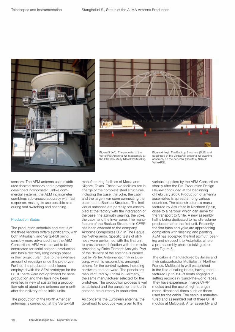
Figure 3 (left): The pedestal of the VertexRSI Antenna #2 in assembly at the OSF (Courtesy NRAO/VertexRSI).
manufacturing facilities of Mexia and Kilgore, Texas. These two facilities are in charge of the complete steel structures, including the base, the yoke, the cabin and the large Invar cone connecting the cabin to the Backup Structure. The indi-vidual antennas are partially pre-assem-bled at the factory with the integration of the base, the azimuth bearing, the yoke, the cabin and the Invar cone. The manu-facture of the Backup Structure in CFRP has been awarded to the company Airborne Composites B.V. in The Hague, the Netherlands. Specific tests of stiff-ness were performed with the first unit to cross-check deflection with the results provided by Finite Element Analysis. Part of the delivery of the antenna is carried out by Vertex Antennentechnik in Duis-burg, which is responsible, amongst others, for the control system, including hardware and software. The panels are manufactured by Zrinski in Germany, the same manufacturer selected for the prototype. The production process is well established and the panels for the fourth antenna are currently in production.
As concerns the European antenna, the go-ahead to produce was given to the
various suppliers by the AEM Consortium shortly after the Pre-Production Design Review concluded at the beginning of February 2007. Production of antenna assemblies is spread among various countries. The steel structure is manu-factured by Asturfeito in Northern Spain, close to a harbour which can serve for the transport to Chile. A new assembly hall is being dedicated to handle volume production after the first unit. Presently, the first base and yoke are approaching completion with finishing and painting. AEM has accepted the first azimuth bear-ing and shipped it to Asturfeito, where a pre-assembly phase is taking place (see Figure 5).
The cabin is manufactured by Jallais and their subcontractor Multiplast in Northern France. Multiplast is well established in the field of sailing boats, having manu-factured up to 120-ft boats engaged in setting records in round-the-world races. They have experience in large CFRP moulds and the use of high-strength mono-directional fibres such as those used for the cabin. The cabin is manufac-tured and assembled out of three CFRP moulds at Multiplast. After assembly and
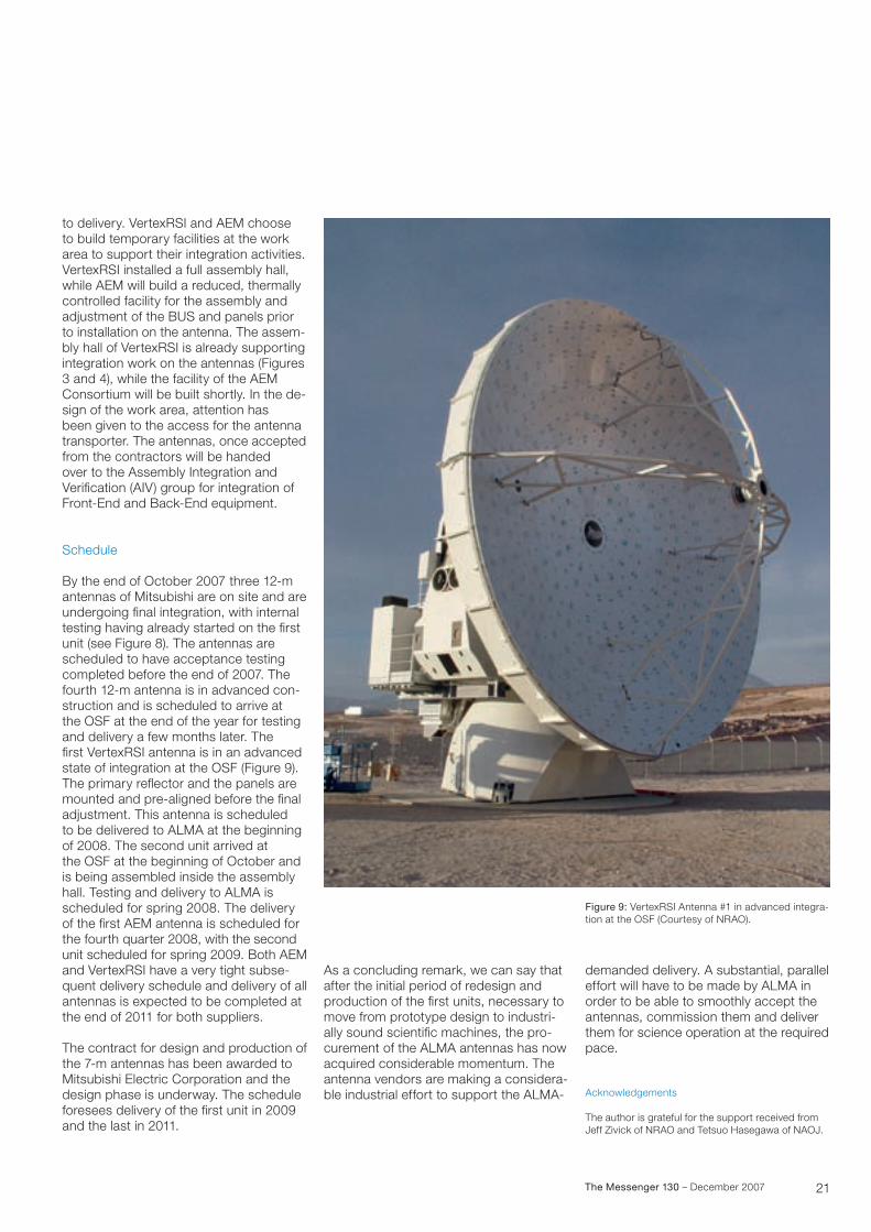
Figure 4 (top): The Backup Structure (BUS) and quadripod of the VertexRSI antenna #2 awaiting assembly on the pedestal (Courtesy NRAO/ VertexRSI).

19The Messenger 130 – December 2007
installation of stiffeners, it is shipped to Jallais in Nantes where all the metallic interfaces are assembled and machined on special jigs. The internal walls of the receiver room will be protected by flame-sprayed aluminium for electromagnetic compatibility, and the cabin will be e quipped with cabin floor, air conditioning heat exchanger, lights and various other fixtures. At the time of writing the first cabin is being equipped with linear motor interfaces (as shown in Figure 6), the floor and other installations, prior to transport to Asturfeito for mounting on the steel structure. Manufacturing of the second and third units has started.
The BUS of the AEM antenna is manufac-tured by Duqueine Composite in France. The first slices have been produced and the integration of the BUS has started (see Figure 7). Special tools have been developed from those originally used for assembling the prototype BUS, demand-ing less manual adjustment to reach the defined precision level. Once assembled, the BUS will be equipped with the panel adjusters, produced by RUAG in Switzer-land. A pre-assembly of the panels and the apex structure is planned in Europe. The BUS will then be separated in two halves and prepared for transport. The production of the nickel-deposited repli-cated panel is proceeding at full speed, clearly profiting from the fact that the design remains unchanged from the pro-totype design. The Italian-based supplier, Media Lario Technologies, has increased its manufacturing facilities to be able to serve the demanded delivery schedule. The panels for the third antenna are now in production.
Finally, the remaining equipment is being produced by various suppliers, with con-trol system and metrology delivered by Microgate, the linear motors by Phase Motion Control in Italy and the quadripod legs manufactured in Germany by Xperion. The equipment is first internally accepted by AEM, in a process which is closely mon itored by ESO, prior to integration into the antenna.
Figure 5: AEM base (upper) and yoke (lower) in manufacturing (Courtesy of AEM Consortium/Astrurfeito).
Figure 6: Mounting of the elevation linear motor on the AEM antenna cabin (Courtesy of AEM Consortium/Jallais).

20 The Messenger 130 – December 2007
The Mitsubishi 12-m antennas are cur-rently the most advanced. Three anten-nas have been produced so far, almost completely assembled at the Osaka factory, and then shipped to Chile where they arrived in July 2007. The fourth antenna is in production and is close to being shipped.
On-site assembly
A large work area at the OSF was put at the disposal of the three contractors by ALMA to perform their integration activities. ALMA has reviewed the design of the respective work areas, levelled the surface and installed a number of antenna pads, identical to those to be constructed at the high site, for perform-ing erection work and final acceptance. In each of the work areas, more than one antenna station can be used for the test-ing and acceptance of the antennas. In particular, the front antenna pad(s) can be illuminated with the holography trans-mitter mounted on the holography tower for setting the surface accuracy prior Figure 8: Mitsubishi Antennas in testing at the OSF
(Courtesy NAOJ/Mitsubishi Electric Corporation).
Telescopes and Instrumentation Stanghellini S., Status of the ALMA Antenna Production
Figure 7: Assembly of the BUS of the first AEM antenna. (Courtesy of AEM Consortium/Duqueine Composites).
21The Messenger 130 – December 2007
Figure 9: VertexRSI Antenna #1 in advanced integra-tion at the OSF (Courtesy of NRAO).
to delivery. VertexRSI and AEM choose to build temporary facilities at the work area to support their integration activities.VertexRSI installed a full assembly hall, while AEM will build a reduced, thermally controlled facility for the assembly and adjustment of the BUS and panels prior to installation on the antenna. The assem -bly hall of VertexRSI is already supporting integration work on the antennas (Figures 3 and 4), while the facility of the AEM Consortium will be built shortly. In the de -sign of the work area, attention has been given to the access for the antenna transporter. The antennas, once accepted from the contractors will be handed over to the Assembly Integration and Verification (AIV) group for integration of Front-End and Back-End equipment.
Schedule
By the end of October 2007 three 12-m antennas of Mitsubishi are on site and are undergoing final integration, with internal testing having already started on the first unit (see Figure 8). The antennas are scheduled to have acceptance testing completed before the end of 2007. The fourth 12-m antenna is in advanced con-struction and is scheduled to arrive at the OSF at the end of the year for testing and delivery a few months later. The first VertexRSI antenna is in an advanced state of integration at the OSF (Figure 9). The primary reflector and the panels are mounted and pre-aligned before the final adjustment. This antenna is scheduled to be delivered to ALMA at the beginning of 2008. The second unit arrived at the OSF at the beginning of October and is being assembled inside the assembly hall. Testing and delivery to ALMA is scheduled for spring 2008. The delivery of the first AEM antenna is scheduled for the fourth quarter 2008, with the second unit sched uled for spring 2009. Both AEM and VertexRSI have a very tight subse-quent delivery schedule and delivery of all antennas is expected to be completed at the end of 2011 for both suppliers.
The contract for design and production of the 7-m antennas has been awarded to Mitsubishi Electric Corporation and the design phase is underway. The schedule foresees delivery of the first unit in 2009 and the last in 2011.
As a concluding remark, we can say that after the initial period of redesign and production of the first units, necessary to move from prototype design to industri-ally sound scientific machines, the pro-curement of the ALMA antennas has now acquired considerable momentum. The antenna vendors are making a considera-ble industrial effort to support the ALMA-
demanded delivery. A substantial, parallel effort will have to be made by ALMA in order to be able to smoothly accept the antennas, commission them and deliver them for science operation at the required pace.
Acknowledgements
The author is grateful for the support received from Jeff Zivick of NRAO and Tetsuo Hasegawa of NAOJ.

Ast
rono
mic
al S
cien
ce
Near-infrared image of the Tarantula nebula (30 Doradus,NGC 2070) in the Large Magellanic Cloud taken by HAWK-I during commissioning. The colour composite is composed of three exposures in the filters J, K and Brackett-g. Image taken by the HAWK-I team and processed by Hans Hermann Heyer (ESO)