status on monalisa presented by d. urner 6 th stabilization day 9. june 09
TRANSCRIPT

Status onMONALISA
presented by D. Urner
6th stabilization day
9. June 09

Progress on mechanical setup
• Double bellow system:
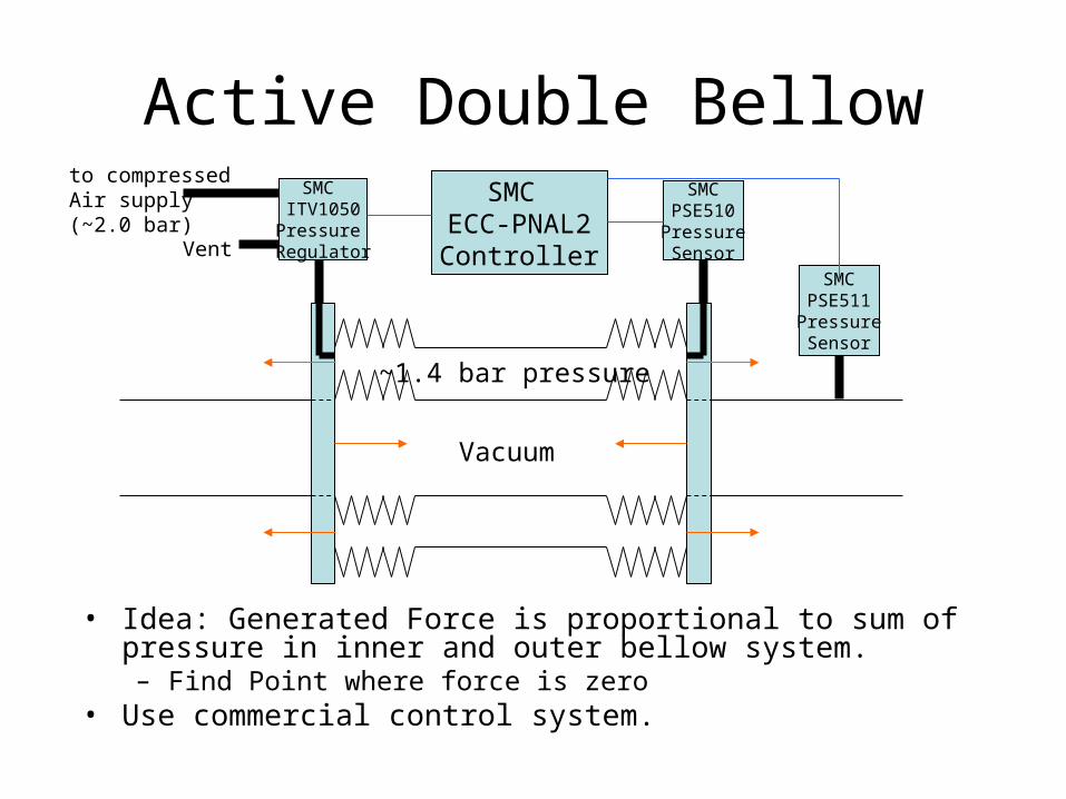
Vacuum
~1.4 bar pressure
SMC ITV1050Pressure Regulator
to compressedAir supply(~2.0 bar)
Vent
SMCPSE510PressureSensor
SMCPSE511PressureSensor
SMC ECC-PNAL2
Controller
• Idea: Generated Force is proportional to sum of pressure in inner and outer bellow system. – Find Point where force is zero
• Use commercial control system.
Active Double Bellow

Progress on mechanical setup
• Double bellow system:– development geared
towards minimal force system
– development with Platine Prcision Ltd. started Sep 08
– full assembly of double bellow to double flanges this week
– shipped to Oxford by end of week
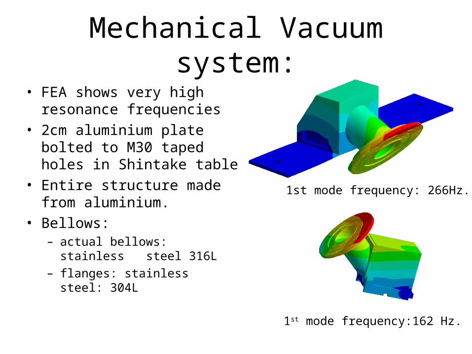
Mechanical Vacuum system:
1st mode frequency: 266Hz.
• FEA shows very high resonance frequencies
• 2cm aluminium plate bolted to M30 taped holes in Shintake table
• Entire structure made from aluminium.
• Bellows: – actual bellows: stainless
steel 316L– flanges: stainless steel: 304L
1st mode frequency:162 Hz.

How to insert optics
• Insert optics platform– rests on very thin
aluminium floor– essential a square
piece of carbon-fibre loaded peak (plastic) holding retro-reflectors
– easy to change to different (optics) geometries
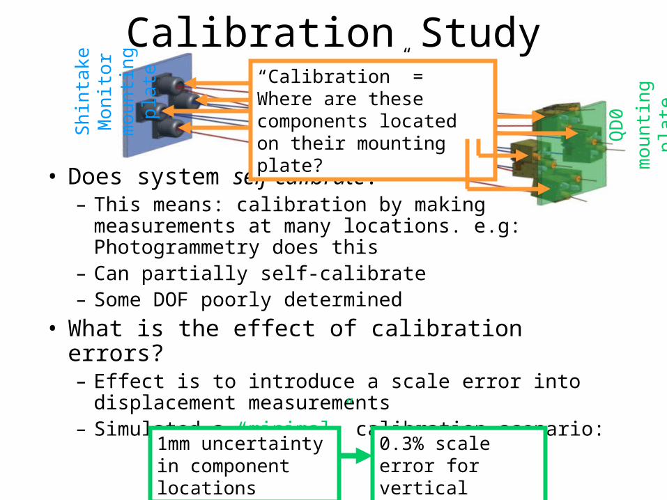
Calibration Study
• Does system self-calibrate?– This means: calibration by making measurements at
many locations. e.g: Photogrammetry does this– Can partially self-calibrate– Some DOF poorly determined
• What is the effect of calibration errors?– Effect is to introduce a scale error into displacement
measurements– Simulated a “minimal” calibration scenario:
“Calibration” = Where are these components located on their mounting plate?
Sh
inta
ke M
oni
tor
mo
un
ting
pla
te
QD
0
mo
un
ting
pla
te
1mm uncertainty in component locations
0.3% scale error for vertical motion

Calibration Study
• What is the effect of calibration errors?– Effect is to introduce a scale error into displacement
measurements– Simulated a “minimal” calibration scenario:
– e.g vibrations with amplitude 1μm would be limited in reconstructed accuracy to 3nm from calibration
– a long-term shift of 100 μm would be limited in reconstructed accuracy to 300nm
“Calibration” = Where are these components located on their mounting plate?
Sh
inta
ke M
oni
tor
mo
un
ting
pla
te
QD
0
mo
un
ting
pla
te
1mm uncertainty in component locations
0.3% scale error for vertical motion

MONALISA at CLIC
• Start with 3 vertical lines– launch heads will be produced for KEK and CLIC by end of year– Need vertical tubes, ideally of 200 mm diameter
• Later add horizontal measurement – Need 200 mm horzontal tube– As much space at intersection as we can get.