std-spe-g-009 supplement to as 1657-2013 fixed …
TRANSCRIPT
ABN 86 069 381 960
STD-SPE-G-009
SUPPLEMENT TO AS 1657-2013 FIXED PLATFORMS, WALKWAYS, STAIRWAYS AND LADDERS – DESIGN,
CONSTRUCTION AND INSTALLATION

© 2017 Icon Water Limited (ABN 86 069 381 960) This publication is copyright and contains information that is the property of Icon Water Limited. It may be used and reproduced only for the purposes of designing and constructing assets which will, if accepted by Icon Water, form part of Icon Water’s water/wastewater networks and facilities (Icon Water Purposes).
Disclaimer
This document has been prepared for Icon Water Limited for the Icon Water Purposes only. Icon Water does not make any warranties or representations in relation to or assume any duty of care with respect to, and is otherwise not responsible for the suitability of this document for any purpose other than the Icon Water Purposes.

Table of Contents Abbreviations ............................................................................................................................ i 1 Background ........................................................................................................................ 1 2 Scope ................................................................................................................................. 2 3 Purpose .............................................................................................................................. 2 4 Referenced documents ...................................................................................................... 3 5 Amendments and additions to AS 1657 .............................................................................. 4

STD-SPE-G-009 Supplement to AS 1657-2013 Page i
Abbreviations
AS, AS/NZS Australian standard; joint Australian and New Zealand standard
Icon Icon Water Limited
NCC National Construction Code
SiD Safety in Design
WSA, WSAA Water Services Association of Australia

STD-SPE-G-009 Supplement to AS 1657-2013 Page 1 of 20
1 Background Like many Australian urban water utilities, Icon Water specifies the use of AS 1657 as a basis for the design, construction and installation of fixed platforms, walkways, stairways and ladders. AS 1657 is referenced within Icon Water’s suite of design standards. This suite of standards comprises standard drawings, specifications, integrated WSAA codes, supplements to WSAA codes, supplements to Australian and international standards as well as rules.
The issue of full compliance with AS 1657 for assets located within, and forming part of water and sewerage networks and facilities does cause some debate and differing interpretations amongst designers and Icon Water staff. The committee of AS 1657 has acknowledged that full compliance with the Australian standard may not always be possible within the urban water utility environment. This is evidenced by the note on page 5 of AS 1657 located after Section 1.1 point (c) which states that:
This standard may also be used for guidance in providing access to some parts of mobile plant, light and telecommunications towers, wind turbine towers and water and sewerage facilities. While such access may not be capable of complying with all the requirements of this standard, the principles and imposed actions should be followed.
An example of where AS 1657 cannot be fully complied with is the situation relating to maintenance holes located within the sewerage network...
• In such a situation, full compliance with AS 1657 would require the top rung of the fixed internal ladder to finish level with the top of the maintenance hole. This cannot be achieved due to the requirement that the top of the removable cover finishes flush with its surrounds.
• Similarly, specific ladder clearances are required which cannot be achieved with an industry standard 600 mm nominal diameter removable cover or within a standard DN1050 maintenance hole. Larger covers and larger maintenance holes would add significant extra cost for a hard-to-quantify decrease in likelihood of a potential worker injury given that (i) the use of limited free-fall arrest systems are standard operating practice when accessing and egressing such assets, and (ii) Icon safety records do not show any difference in injury rates when accessing pits, chambers, wells and maintenance holes through different sized openings.
• Furthermore, traversing the ladder to the bottom of the maintenance hole would require the worker to ultimately stand on a benched rather than flat landing – this situation is not catered for in the specific requirements of AS 1657.
This supplement aids to address these types of issues so that AS 1657, in-conjunction with this supplement, is the only document set which specifies mandatory requirements for the design and construction of stairways, ladders, platforms and walkways for assets found within Icon Water’s water/sewerage networks and facilities. Typically, these types of issues relate predominantly to buried maintenance structures which may or may not protrude above ground level and have some form of cover and access hatch arrangement.
It should be noted that there are requirements within this document that are not strictly prescribed in AS 1657. These requirements have been chosen as the most appropriate way to apply the principles and imposed actions of AS 1657 within an urban water utility environment given that full compliance with AS 1657 in such an environment may not be reasonably practicable in all situations (as acknowledged on page 5 of AS 1657).
STD-SPE-G-009A AS 1657-2013 Supplement Page 2 of 20
2 Scope This supplement:
a) Shall apply to the design, construction and installation of permanently fixed guardrails, platforms, walkways, stairways, ladders and step-irons.
b) Must be fully complied with by designers, suppliers, specifiers and constructors.
c) Is applicable to the asset areas shown in the Document Applicability Table. Note: This table is located in the section immediately prior to the table of contents.
d) Must be read in-conjunction with the documents listed in Table 4.1.
3 Purpose The purpose of this supplement is to outline amendments and additions to AS 1657 (2013 version incorporating Amendment No.1 issued in 2016) for cases where:
a) Icon Water has more stringent requirements, or has implemented other remedies which provide the same or a lower rating of risk with respect to a worker fall which may cause injury.
b) Where AS 1657 is effectively “silent” with respect to stairway, ladder, platform and walkway requirements for certain types of water and sewerage assets (such as buried maintenance structures).
c) The National Construction Code (NCC) provides alternative requirements which have been assessed by Icon Water as being more applicable/suitable than AS 1657 for a particular asset type.

STD-SPE-G-009A AS 1657-2013 Supplement Page 3 of 20
4 Referenced documents The documents listed in Table 4.1 are either referenced by this supplement, or shall be read in-conjunction with this specification. Note: The latest versions should be consulted.
Table 4.1 Referenced Documents
Item Document number Title
Australian standards
1 AS 1657 Fixed platforms, walkways, stairways and ladders – Design, construction and installation
2 AS/NZS 1891.4 Industrial fall-arrest systems and devices – Selection, use and maintenance
3 AS 2865
Safe working in a confined space
4 AS 4586
Slip resistance classification of new pedestrian surface materials
5 AS/NZS 5532 Manufacturing requirements for single-point anchor device for harness-based work at height
SafeWork Australia (and WorkSafe ACT) Codes of Practice
6 Not provided
Managing the risk of falls at workplaces
WSAA codes and publications
7 WSA 201 Manual for the selection and application of protective coatings
Icon standards and work instructions
8 STD-SPE-G-005 Supplement to WSA 201 Manual for the selection and application of protective coatings
9 STD-SPE-G-008 Technical specification - Design requirements for safe access, egress and working at heights
10 WI7.1.1 Risk assessment tables

STD-SPE-G-009A AS 1657-2013 Supplement Page 4 of 20
5 Amendments and additions to AS 1657 This section provides amendments and additions to AS 1657 (2013 version incorporating Amendment No. 1 issued in 2016). These amendments and additions shall be treated by designers, suppliers, specifiers and constructors as being mandatory requirements which either supersede or supplement (as applicable) the requirements of AS 1657.
It is noted that AS 1657 with or without these amendments and additions may not be able to be fully complied with when fixed ladders, platforms, walkways and guardrails etc. are being designed, constructed and installed for Icon Water’s existing assets. In such circumstances, the principles and imposed actions of AS 1657, in-conjunction with this supplement shall be followed. Furthermore, in such circumstances, the Icon Water SiD process which incorporates systematic hazard analysis and risk assessment, shall be used to eliminate, or if it is not possible to eliminate, to at least mitigate the level of risk associated with the design of such assets to as low as reasonably practicable.
Table 5.1 Amendments and additions to AS 1657
No. AS 1657 Ref. Amendment and/or addition
1 Page 5 Section 1.1
Re-word the note directly after point (c) as follows… NOTE: This standard, without a supplement, may not be able to be fully complied with for the design and construction of access methods for structures and equipment found within the urban water industry such as but not limited to buried maintenance structures, reservoirs and similar assets. In such instances, the principles and imposed actions should be followed.
2 Page 7 Section 1.5
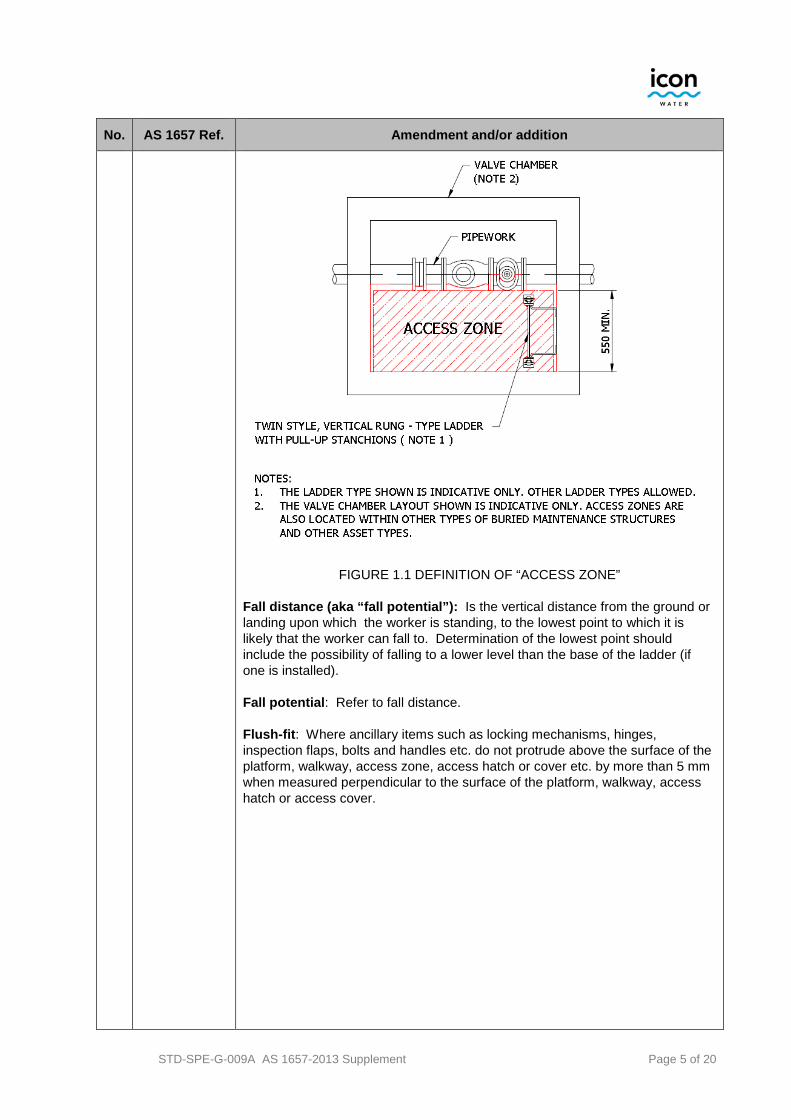
Add the following definitions… Access zone: The bottom floor (i.e. surface) of a buried maintenance structure (e.g. flowmeter chamber, valve chamber or water meter pit). Access zones shall have a minimum unencumbered width of 550 mm. An access zone is not a walkway. Note: The internal surfaces of tanks, pipes, launders etc. may at times of maintenance activity be classes as temporary access zones. Note: When a ladder is located within an access zone, the landing area shall extend at least 600 mm in front of the ladder. Refer to Table 5.1 Item No. 43 for further details.
STD-SPE-G-009A AS 1657-2013 Supplement Page 5 of 20
No. AS 1657 Ref. Amendment and/or addition
FIGURE 1.1 DEFINITION OF “ACCESS ZONE” Fall distance (aka “fall potential”): Is the vertical distance from the ground or landing upon which the worker is standing, to the lowest point to which it is likely that the worker can fall to. Determination of the lowest point should include the possibility of falling to a lower level than the base of the ladder (if one is installed). Fall potential: Refer to fall distance. Flush-fit: Where ancillary items such as locking mechanisms, hinges, inspection flaps, bolts and handles etc. do not protrude above the surface of the platform, walkway, access zone, access hatch or cover etc. by more than 5 mm when measured perpendicular to the surface of the platform, walkway, access hatch or access cover.
STD-SPE-G-009A AS 1657-2013 Supplement Page 6 of 20
No. AS 1657 Ref. Amendment and/or addition
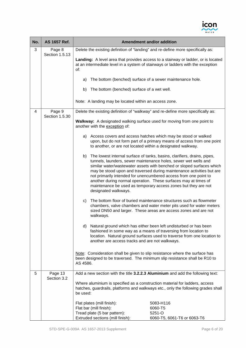
3 Page 8 Section 1.5.13
Delete the existing definition of “landing” and re-define more specifically as: Landing: A level area that provides access to a stairway or ladder, or is located at an intermediate level in a system of stairways or ladders with the exception of:
a) The bottom (benched) surface of a sewer maintenance hole.
b) The bottom (benched) surface of a wet well.
Note: A landing may be located within an access zone.
4 Page 9 Section 1.5.30
Delete the existing definition of “walkway” and re-define more specifically as: Walkway: A designated walking surface used for moving from one point to another with the exception of:
a) Access covers and access hatches which may be stood or walked upon, but do not form part of a primary means of access from one point to another, or are not located within a designated walkway.
b) The lowest internal surface of tanks, basins, clarifiers, drains, pipes,
tunnels, launders, sewer maintenance holes, sewer wet wells and similar water/wastewater assets with benched or sloped surfaces which may be stood upon and traversed during maintenance activities but are not primarily intended for unencumbered access from one point to another during normal operation. These surfaces may at times of maintenance be used as temporary access zones but they are not designated walkways.
c) The bottom floor of buried maintenance structures such as flowmeter
chambers, valve chambers and water meter pits used for water meters sized DN50 and larger. These areas are access zones and are not walkways.
d) Natural ground which has either been left undisturbed or has been fashioned in some way as a means of traversing from location to location. Natural ground surfaces used to traverse from one location to another are access tracks and are not walkways.
Note: Consideration shall be given to slip resistance where the surface has been designed to be traversed. The minimum slip resistance shall be R10 to AS 4586.
5 Page 13 Section 3.2
Add a new section with the title 3.2.2.3 Aluminium and add the following text: Where aluminium is specified as a construction material for ladders, access hatches, guardrails, platforms and walkways etc., only the following grades shall be used: Flat plates (mill finish): 5083-H116 Flat bar (mill finish): 6060-T5 Tread plate (5 bar pattern): 5251-O Extruded sections (mill finish): 6060-T5, 6061-T6 or 6063-T6

STD-SPE-G-009A AS 1657-2013 Supplement Page 7 of 20
No. AS 1657 Ref. Amendment and/or addition
6 Page 15 Section 3.3.4
Add an additional note as follows: This does not apply to access hatches which are not located in designated walkways or access zones. For example, access hatches which are not located within walkways delineated by a yellow painted line or access hatches which are protected by bollards, fencing or guardrails.
7 Page 17 Section 4.3
Add a note after point (f) as follows: This does not apply to access hatches which are not located in designated walkways. Otherwise, if an access hatch is located within a designated walkway on a platform surface, it must be designed such that it fully complies with Section 4.3 points (a) to (f) inclusive and it must also be flush-fit (as defined in Section 1.5).
8 Page 17 Section 4.4
Amend point (c) onwards as follows…
c) On the top surface of a buried maintenance structure (such as a valve chamber) which is higher than the surrounding area and meets all of the following four criteria:
i. the top surface of the buried maintenance structure has a
minimum diameter of 1200 mm or, in the case of non-circular maintenance structures, a minimum width and length combination of 1200 mm x 1200 mm (for hinged access hatches) or 1200 x 2400 mm (for lift-off circular access hatches).
ii. the fall potential from the top surface of the buried maintenance
structure to the surrounding area is limited to a maximum of 600 mm.
iii. the surrounding area (which would be landed on in the event of
a worker fall) has a maximum cross-slope and/or slope away from the chamber of 15°. Note: The surrounding area extends to a maximum of 1500 mm perpendicular to any face of the maintenance structure.
iv. the surrounding area (as defined in Item (iii) above) is free of
any permanently installed sharp-edged objects (including plants and bushes) which protrude above the surface as well as any environmental hazards.
d) On the sides and edges of a platform (which is not the top surface of a
buried maintenance structure), the level of which is not greater than 300 mm above that of an adjacent platform or floor, provided –
i. the smallest dimension of the upper platform is not less than
1200 mm; and
ii. the distance from any edges of the unprotected upper platform to the protection on the edge of the lower platform is not less than 1000 mm.

STD-SPE-G-009A AS 1657-2013 Supplement Page 8 of 20
No. AS 1657 Ref. Amendment and/or addition
C4.4: The requirements of Item 4(c) have been provided in an effort to maintain some consistency with the NCC. This is due the fact that buried maintenance structures are commonly located within the urban environment as are building structures such as retaining walls, decks, platforms, benches and stages, all of which must meet the requirements of the NCC. The fall potential (and hence risk rating) arising from a fall from a 600 mm high deck without guardrailing (which is allowed under the requirements of the NCC) is the same as that of a fall from a buried maintenance structure protruding 600 mm above ground level. Grassed areas, concrete, pavers, hardstand and natural ground (which has been cleared and grubbed) can be taken to be in compliance with the requirements of Item 4(c). Icon Water requires temporary barriers (or other suitable remedies such as approved restraint systems) to be installed when the fall potential has been risk-assessed by workers as being such that the likelihood and consequence of injury is at least “unlikely” and “minor” respectively. Note: Where it is not possible to apply the requirement of Item (d)(ii) above, the minimum height of the protection at the edge of the lower platform shall be increased by 300 mm. The unprotected edges of such platforms shall be marked so that they are clearly visible in their surroundings. Refer to Figure 4.1 for graphical details of guardrails on various platforms (excluding the top surface of buried maintenance structures). Refer to Figures 4.2, 4.3A and 4.3B for graphical details relating to buried maintenance structures with respect to guardrails (i.e. point (c) above).

STD-SPE-G-009A AS 1657-2013 Supplement Page 9 of 20
No. AS 1657 Ref. Amendment and/or addition
9 Page 18 Section 4.4
Add the following graphics…
FIGURE 4.2 GUARDRAIL EXEMPTIONS – CIRCULAR BURIED MAINTENANCE STRUCTURES
FIGURE 4.3A GUARDRAIL EXEMPTIONS – NON-CIRCULAR BURIED MAINTENANCE STRUCTURES WITH HINGED ACCESS HATCHES

STD-SPE-G-009A AS 1657-2013 Supplement Page 10 of 20
No. AS 1657 Ref. Amendment and/or addition
FIGURE 4.3B GUARDRAIL EXEMPTIONS – NON-CIRCULAR BURIED MAINTENANCE STRUCTURES WITH LIFT-OFF CIRCULAR HATCHES
10 Page 19
Section 4.6
Delete all text and reword as follows… Where it has been determined in accordance with Section 4.4 that guardrailing is a requirement, then a toeboard complying with Clause 6.1.2 shall also be provided unless (i) the fall potential is limited to a maximum of 600 mm, or if the fall potential is greater than 600 mm (ii) there is a permanent structure within 10 mm of the edge of the platform or landing which will prevent an object falling onto an area below or the area below is non trafficable. Note: With respect to toeboards, “fall potential” refers to how far (measured in the vertical) an object (which is of a size and weight which makes it capable of being accidently kicked over an edge) will fall to land on a worker below.
C4.6 Toeboards have the primary purpose of preventing tools and other small objects (which are of such a weight that they will move when accidently kicked) from falling on to a worker below. The injury potential of a small object such as a hand tool which falls 600 mm onto a worker’s leg or foot has been pre-assessed in accordance with Icon Water’s risk assessment procedures as being “negligible”.

STD-SPE-G-009A AS 1657-2013 Supplement Page 11 of 20
No. AS 1657 Ref. Amendment and/or addition
11 Page 19 (new section
4.8 to be added)
Add a new section below Section 4.7 Edges with the title Section 4.8 Self-Closing Gates. Add the following text (including commentary) for this new section as follows… A self-closing gate shall be installed at the point of access at the top of every twin style rung and step ladder when fixed guardrailing is also installed along the same edge that a worker would have to cross when accessing the ladder. Self-closing gates are not required when permanently fixed guardrailing is not installed. Self-closing gates shall always open in a direction away from the worker when the worker is standing on the ladder. Self-closing gates shall always close so that a worker who leans or falls onto the gate whilst standing on the landing will not cause the gate to open due to the force associated with leaning or falling. C4.8 Self-closing gates are not required when permanently installed guardrailing is not installed as Icon Water requires approved temporary barrier systems, and/or approved restraint systems to be used by workers in such instances.
12 Page 24 Section 5.5
Delete all text and reword as follows… Toeboards are not required if the fall potential is limited to a maximum of 600 mm. Otherwise, a toeboard complying with Clause 6.1.2 shall be installed on the edge of a walkway where there is no permanent structure within 10 mm of the edge, and from which an object could fall to where persons have access to the area below and to the side of the walkway. Any gap between the underside of the toeboard and the walkway surface shall not be greater than 10 mm. The top of the toeboard shall not be less than 100 mm above the floor. C5.5 As per Section 4.6, the injury potential of a small object such as a hand tool which falls 600 mm onto a worker’s lower leg and/or foot has been pre-assessed in accordance with Icon Water’s risk assessment procedures as being “negligible”. This is based on Icon Water’s requirement for fully enclosed footwear with protective (steel) toecaps being worn in-conjunction with long pants or overalls.

STD-SPE-G-009A AS 1657-2013 Supplement Page 12 of 20
No. AS 1657 Ref. Amendment and/or addition
13 Page 31 Section 7.1.2
Add the following text immediately below the title 7.1.2 Fixed Ladders… Fixed ladders and step irons located within environments determined to be “High” or “Immersion” in accordance with Table 2.1 of WSA 201 Manual for the selection and application of protective coatings shall be constructed of grade 316 stainless steel. This includes all fixings and ancillaries. Fixed ladders and step irons located within environments determined to be “Low” or “Moderate” in accordance with Table 2.1 of WSA 201 Manual for the selection for the selection and application of protective coatings may be constructed of hot-dipped galvanised carbon steel or grade 316 stainless steel. Aluminium may also be used within these environments but not for the construction of step irons. C7.1.2 Ladders located within an enclosed sewer environment where corrosive gases are present in sufficient volumes such as sewer pump station wet wells and sewerage maintenance holes require the use of grade 316 stainless steel.
14 Page 31 Section 7.1.2.2
Delete all text beneath the title 7.1.2.2 Single-stile ladders and replace with the following text… Single-stile ladders shall not be used.
15 Page 31 Section 7.1.2.3
Add the following text below the first paragraph… With the exception of sewer maintenance holes of a nominal diameter of 1050 mm, step-irons shall not be used. C7.1.2.3 Whilst some urban water utilities have stopped the practice of installing step irons due to corrosion-related weakness and failure issues, Icon Water maintenance personnel prefer to have the option of using step irons as a secondary means of egress from 1050 mm nominal diameter maintenance holes in the event of an emergency. This is even though workers are lowered into and out of such structures, and Type 3 SRLs are used in conjunction with davits or tripods complying with Icon Water’s Approved Products List as part of emergency response plans.
16 Page 32 Figure 7.1
Delete Figure 7.1.
17 Page 39 Section 7.3.6
Re-word Item (b) as follows: The width of the landing shall not be less than the width of the ladder or 600 mm, whichever is the greater, except for when the landing is located within an access zone. In such instances, the minimum width of the landing shall be 600 mm, or if this is not possible, it shall be the width of the access zone.

STD-SPE-G-009A AS 1657-2013 Supplement Page 13 of 20
No. AS 1657 Ref. Amendment and/or addition
18 Page 40 Section 7.4.3.3
Delete all text beneath the title 7.4.3.3 Variation of top rung/tread spacing and replace with the following text… The top rung/tread shall be level with the top landing, as shown in Figure 7.5 with the exception of installations which require a permanently installed access hatch with its top surface at the same level or higher than the top landing. In such circumstances, the pitch of the rungs shall be evenly spaced with the final step from the top ladder rung to the top landing as shown in Figure 7.5A or Figure 7.5B as applicable. C7.4.3.3 Whilst it is commonplace for portable ladders, it should be noted that a worker who is forced to take an uneven step onto a landing from a ladder has a higher risk of falling. If an access hatch or cover prevents the top rung from sitting level with the top of the landing, then the rungs shall be evenly spaced and such that a step from the final rung of the ladder onto the landing will not result in an uneven step (with the exception of sewer maintenance holes fitted with 600 mm nominal diameter access covers where such a requirement is impracticable).
19 Page 41 Section 7.4.3.3
Add the following graphics…
FIGURE 7.5A VARIATION OF RUNG/TREAD SPACING WITH PERMANENTLY INSTALLED ACCESS HATCHES.

STD-SPE-G-009A AS 1657-2013 Supplement Page 14 of 20
No. AS 1657 Ref. Amendment and/or addition
FIGURE 7.5B VARIATION OF RUNG/TREAD SPACING WITH SEWER MAINTENANCE HOLES.
20 Page 42
Section 7.4.3.4
Delete the first paragraph and replace with the following text… The distance between the bottom rung/tread and the bottom landing shall not be less than 90% and not greater than 100% of the rung/tread spacing (see Figure 7.5) with the exception of sewer maintenance holes, sewer pump station wet wells and other assets which have their lower surface benched. In such instances, the bottom rung of the ladder shall finish wherever practicable 90% to 100% of the rung/tread spacing but not outside the limits of 200 to 300 mm above the surface immediately below the ladder (upon which a worker will stand when stepping off the ladder).
21 Page 42 Section 7.4.5
Delete the first sentence and replace with the following text: With the exception of sewer maintenance holes and scour chambers which have access covers of dia. 600 mm nominal and 600 x 600 mm nominal respectively, the minimum clearances between the ladder and all permanent objects that are not part of the ladder installation shall be the following:
22 Add a new paragraph directly above the note as follows… For sewer maintenance holes and scour chambers which have covers of the sizes nominated above, once the worker has accessed through the cover, the minimum clearances must be in accordance with all of the above-mentioned details in this section.

STD-SPE-G-009A AS 1657-2013 Supplement Page 15 of 20
No. AS 1657 Ref. Amendment and/or addition
23 Page 43 Section 7.4.7
Re-word the third paragraph (directly above the notes) as follows… Where the installation of a ladder cage is not possible (e.g. sewer maintenance holes, scour chambers, wet wells and the like) a fall arrest system meeting the requirements of Icon Water’s Approved Products List shall be provided.
24 Page 48 Section 7.4.8.2
Re-word the first paragraph as follows… Where it is necessary for a person to step sideways from a ladder, the ladder stiles and rungs shall extend not less than 1000 mm above the top landing except when a wall, guardrailing or other such barrier is behind the ladder which would prevent the worker from falling through the ladder. Refer to Figure 7.10A. Include Figure 7.10A. directly below Figure 7.10 as follows…
FIGURE 7.10A TYPICAL SIDE ACCESS LADDER WITH BARRIER TO PREVENT FALLING THROUGH
25 Page 48
Section 7.4.8.3
Re-word the first paragraph as follows… With the exception of sewer maintenance holes, when access is provided through a horizontal opening of any type –
26 Add commentary below the last paragraph as follows… C7.4.8.3 Sewer maintenance holes are fitted with industry standard 600 mm nominal diameter access covers. These covers make the use of extendable or removable stanchions above the top of the ladder impracticable. Icon Water requires the use of limited free fall arrest equipment when accessing these structures for fall potentials greater than 2.0 metres.

STD-SPE-G-009A AS 1657-2013 Supplement Page 16 of 20
No. AS 1657 Ref. Amendment and/or addition
27 Page 49 Section 7.4.8.4
Re-word the first paragraph at the top of page 49 as follows… Where the ladder provides access to a landing, the top rung/tread shall be level with the top landing, as shown in Figure 7.11(a) with the exception of installations which require a permanently installed access hatch with its top surface at the same level or higher than the top landing. In such circumstances, the pitch of the rungs shall be evenly spaced with the final step from the top ladder rung to the top landing as shown in Figure 7.5A or Figure 7.5B as applicable.
28 Add a commentary directly under the last note in this section as follows… C7.4.8.4 A worker who is forced to take an uneven step onto a landing from a ladder has a higher risk of falling. If an access hatch or cover prevents the top rung from sitting level with the top of the landing, then the rungs shall be evenly spaced and such that a step from the final run of the ladder onto the landing will not result in an uneven step (with the exception of sewer maintenance holes fitted with 600 mm nominal diameter access covers where such a requirement is impracticable).
29 Page 51 Section 7.5
Delete sections 7.5.1 through 7.5.9 inclusive and replace with the following text directly underneath the title 7.5 SINGLE STILE LADDERS… Single-stile ladders shall not be used.
30 Page 79 Appendix G Section G1
Add the following paragraph directly underneath the title G1 GENERAL… This section shall be read in-conjunction with Icon Water technical specification STD-SPE-G-008 Design requirements for safe access, egress and working at heights. The details contained within STD-SPE-G-008 are specific to Icon Water and take precedence over the information provided in Appendix G.
31 Page 81 Table G1
Amend Table G1 as follows… For 60° to 70° step-type ladders, for “Other issues”, add the following sentence… For covered buried maintenance structures such as valve pits, consider the need for a second access hatch separate from the access hatch used to access the step-type ladder. This second hatch may be required as part of an emergency response plan if the buried maintenance structure is classified as a confined space in accordance with AS 2865.

STD-SPE-G-009A AS 1657-2013 Supplement Page 17 of 20
No. AS 1657 Ref. Amendment and/or addition
32 Page 82 Table G1
Amend Table G1 as follows… For 70° to 90° rung-type ladders (twin styles), for “Other issues”, delete the existing text and replace with the following…
Ladders at angles greater than 75° require the use of Icon Water approved limited free-fall arrest equipment when the fall potential exceeds 3.0 metres. Ladders exceeding 6 metres in fall distance require a cage or fall protection device. Intended only for single person use. Consider the need for restricted access or locking-off.
For 85° to 90° rung-type ladders (single styles), delete the existing text in the “Considerations”, “Other issues” and “Application” cells, merge all cells together and insert the following text…
Single-style rung-type ladders shall not be used. For 80° to 90° individual rung-type ladders (step irons), for “Other issues”, delete the existing text and replace with the following…
Step irons located within sewer maintenance holes require the use of Icon Water approved limited free-fall arrest equipment for a fall potential greater than 2.0 metres. Single person use only. Must be restricted access and locked off. Only grade 316 stainless steel shall be used. Note: Step irons shall not be used as an anchor as part of a fall arrest system.
33 Page 83
Appendix H
Directly under the title APPENDIX H FALL PROTECTION, delete the word (Informative) and replace with the word (Mandatory).
34 Page 83 Section H1
Directly under the title H1 GENERAL, add the following text… Appendix H provides mandatory requirements which shall be read in-conjunction with Icon Water technical specification STD-SPE-G-008 Design requirements for safe access, egress and working at heights.
35 Re-word the (existing) third paragraph as follows… Once the type of access system is selected, additional fall protection measures may be appropriate. Requirements for fall protection are provided in Table H1 in-conjunction with Icon Water specification STD-SPE-G-008 for the various types of access.

STD-SPE-G-009A AS 1657-2013 Supplement Page 18 of 20
No. AS 1657 Ref. Amendment and/or addition
36 Page 83 Section H3
Re-word the third paragraph as follows… Design loads for fall arrest shall be in accordance with the requirements of AS/NZS 5532 as amended by Icon Water specification STD-SPE-G-008.
37 Page 84 Section H4
Re-word the third paragraph as follows… Where a fall arrest system is specified, it shall comply with Icon Water’s Approved Products List and specification STD-SPE-G-008.
38 Pages 85 & 86 Table H1
Amend the columns of Table H1 so that for “Fall protection for a fall distance of”, the categories are now… 0 m to 3.0 m >3.0 m to 6 m >6 m
39 For 85° to 90° rung-type ladders (single styles), delete the existing text in the “Fall protection for…”, “Platforms and landings” and “Other measures” cells, merge all cells together and insert the following text… Single-style rung-type ladders shall not be used.
40 Add commentary below Note 2(g) as follows… CH4 Icon Water requires that limited free-fall arrest systems are used when (i) accessing twin style rung ladders fixed at angles greater than 75° for fall potentials greater than 3.0 metres, and (ii) for a fall potential greater than 2.0 metres when accessing ladders and step-irons within sewer maintenance holes. This is why the fall distances in Table H1 have been amended to show that harness-based fall-arrest systems are required for fall distances greater than 3.0 metres rather than 3.5 metres.
41 Page 88 Section I2
Replace the word “Informative” with the word “Mandatory” directly under the appendix title and re-word item (a) as follows… (a) Unless access hatches make it impracticable, step-type ladders should
incorporate continuous handrails from the base all the way to the landing, so that the user does not have to let go on the way up (see Figure I1). Where access hatches are installed at the top landing, the use of pull-up stanchions or fixed stanchions at the top landing (which can be rotated out-of-the way as required) should be considered.
42 Re-word item (c) as follows… (b) Unless access hatches make it impracticable and pull-up stanchions are
used, the extended vertical stiles on vertical rung ladders should incorporate “D” shaped handrails, to assist the user during access and egress (see Figure I3).

STD-SPE-G-009A AS 1657-2013 Supplement Page 19 of 20
No. AS 1657 Ref. Amendment and/or addition
43 Page 91 Section I8
Re-word the first paragraph immediately below the title I8 TOP AND BOTTOM LADDER LANDINGS as follows… The landing at the top and bottom of a rung ladder or step-type ladder should be:
a) Level (within a range of 0° to 3°) and flat with the exception of maintenance structures which have benched surfaces such as sewer maintenance holes and sewage pump station wet wells.
b) Of a width not less than 600 mm, except for when the landing is located
within an access zone. In such instances, the minimum width of the landing shall be 600 mm, or if this is not possible, it shall be the width of the access zone.
c) Of a length extending in front of the ladder of not less than 600 mm if
located within an access zone otherwise not less than 900 mm. Refer to Figure I5 for typical landing details for roof access ladders.
44 Add a commentary directly below the second paragraph as follows… CI8 The benched surface located within a buried maintenance structure such as a sewer maintenance hole is typically at a slope of 5° to 6°. Open channels form part of the surface (for the purpose of sewage flow). Operating experience throughout the urban water industry over many decades has shown that the hazards associated with a worker traversing this type of surface are deemed to be as low as reasonably practicable. Benched surfaces found within sewage pump stations wet wells are steeper in gradient than those found in sewage maintenance holes. In such installations, (i.e. slopes greater than 6°) the lowering of maintenance cages or other such means of providing a temporary (level) platform is recommended when workers are required to access such structures for maintenance activities.

STD-SPE-G-009A AS 1657-2013 Supplement Page 20 of 20
This page left intentionally blank

Talk to us
E [email protected] T 02 6248 3111
@iconwater
GPO Box 366, Canberra ACT 2601
iconwater.com.au