steel stud brickveneer design guide
TRANSCRIPT
Steel Stud BrickVeneerDesign Guide
CSSBI S19-08

Steel Stud BrickVeneerDesign Guide
Prepared forCanadian Sheet Steel Building Institute
Prepared byT.W.J. Trestain, P. Eng.T.W.J. Trestain Structural EngineeringToronto, Canada
CSSBI S19-08ISBN 978-1-895535-72-3
Copyright © November 2008Canadian Sheet Steel Building InstituteAll rights reserved. This publication, or any partthereof, may not be reproduced in any formwithout the written permission of the publisher.

CSSBI Steel Stud Brick Veneer Design Guide
Steel Stud Brick Veneer Design Guide Preface This publication is intended as a guide for designers of steel stud brick veneer (SS/BV) wall systems for buildings. The material presented in this publication has been prepared for the general information of the reader. While the material is believed to be technically correct and in accordance with recognized good practice at the time of publication, it should not be used without first securing competent advice with respect to its suitability for any given application. Neither the Canadian Sheet Steel Building Institute, its Members nor T.W.J. Trestain Structural Engineering warrant or assume liability for the suitability of the material for any general or particular use. Scope and Purpose of the Guide This guide has been prepared to assist practicing structural engineers and architects to design steel stud brick veneer systems for commercial and high rise residential build-ings. Low rise residential buildings are excluded because they generally have less ex-posure to environmental and structural loads. Steel stud brick veneer walls are designed to resist out-of-plane wind and earthquake loads and to provide an environmental separation between internal and external condi-tions. The relevant structural and building science1 principles are reviewed. General guidelines for the detailing of these walls are provided along with some specific struc-tural design recommendations. The reference section includes an extensive list the background documents that were relied on in the production of the Guide. See also the companion document to this guide "Lightweight Steel Framing Design Manual, Second Edition" (CSSBI 2006a) where the structural design of the steel stud back-up is treated in detail. Acknowledgements The Canadian Sheet Steel Building Institute (CSSBI) would like to acknowledge the con-tribution of Mr. Tom Trestain, P. Eng. of T.W.J. Trestain Structural Engineering, Toronto, Canada who was retained for the preparation of this publication. Mr. Trestain is experi-enced in the design and erection of lightweight steel framing (LSF) products and is an active member on the CSA Committee for the North American Specification for the De-sign of Cold-Formed Steel Structural Members as well as other voluntary industry com-mittees. He is the author of a number of articles and publications on steel studs and has
1 In the context of this guide, building science refers to controlling the movement of heat, air
and moisture through the wall system.
Page i
CSSBI Steel Stud Brick Veneer Design Guide
served as an advisor on a number of steel stud research projects including the CMHC sponsored research on steel stud brick veneer. This guide is substantially based on the Steel Stud Brick Veneer Design Guide (AISI 2003) published by the American Iron and Steel Institute in 2003. The willingness of the AISI to share portions of the Guide has been gratefully received. The development of this guide has also been greatly assisted by the Dietrich Design Group Inc. who volunteered the CAD linework for the drawings and by Canada Mortgage and Housing Corporation (CMHC) who gave permission to reproduce portions of their reports2. A number of individual engineers have also added their expertise to the project. In par-ticular, Vince Sagan at Simpson Gumpertz & Heger and Professor John Straube at the University of Waterloo, Waterloo, Canada provided help with the warm climate building science issues. Lastly, many helpful comments were provided by the reviewers of the early drafts and their input has improved the Guide considerably.
2 Portions of Drysdale 1991, Trestain 1996 and Posey 1996 have been reproduced where
noted in the Guide. All rights reserved. Reproduced with the consent of CMHC. All other uses and reproductions of this CMHC material are expressly prohibited.
Page ii
CSSBI Steel Stud Brick Veneer Design Guide
Table of Contents
1. Introduction ………………………………………………………………..…… 1.1 Historical Perspective ……………………………………………….……. 1.2 Current Recommendations .……………………………………….……..
2. SS/BV Walls as a System …………………………………………….….……
2.1 Distribution of Loads Between the Steel Stud Back-up and the Brick Veneer ……………………………………….…….……….
2.2 Tie Loads ............................................................................................ 2.3 Veneer Cracking .................................................................................. 2.4 Serviceability – Design Deflection Limit ............................................... 2.5 Pressure Equalization and the Rain Screen Design Principle ............ 2.6 The Interaction Between Air/Vapour Flow, Thermal Performance
and Moisture Accumulation ................................................................. 2.6.1 Winter Considerations ............................................................. 2.6.2 Summer Considerations ..........................................................
3. Design Recommendations ........................................................................ 3.1 Steel Stud Back-Up System ................................................................
3.1.1 Steel Studs .............................................................................. 3.1.2 Ties ..........................................................................................
3.2 Air Barriers and Vapour Retarders ...................................................... 3.2.1 Air Barriers ............................................................................... 3.2.2 Vapour Retarders ....................................................................
3.3 Exterior Sheathings, Exterior Insulation and Moisture Barriers ........... 3.3.1 Exterior Sheathings .................................................................. 3.3.2 Exterior Insulation .................................................................... 3.3.3 Moisture Barriers .....................................................................
3.4 Air Space Size ..................................................................................... 3.5 Weepers and Vents ............................................................................. 3.6 Other Measures to Control Water Penetration ....................................
Page
1 1 2
2
2 6 6 7
10
17 17 19
20 20 20 21 22 22 23 23 23 23 24 24 24 24
Page iii
CSSBI Steel Stud Brick Veneer Design Guide
1. Introduction
1.1 Historical Perspective
Steel stud brick veneer (SS/BV) wall systems have been widely used in the USA and Canada as an economical wall system that combines the pleasing appearance and durability of brick with the structural reliability of steel.
Properly designed and built steel stud brick veneer walls have performed well.
However, particularly in the early years, faults in design or construction have on occasion led to cladding distress and resulted in expensive repairs. In an effort to better define good design and construction practice, a number of initiatives have been undertaken.
In 1986, Canada Mortgage and Housing Corporation3 (CMHC) perceived that
the construction of steel stud brick veneer walls in Canada was proceeding in the absence of the necessary structural and building science knowledge. At that time, they initiated and funded a comprehensive long-term plan for SS/BV research and education that is still continuing. A nation-wide survey was com-missioned (Suter Keller 1986) in order to determine the state-of-the-art of SS/BV construction in Canada. This survey helped identify problem areas and define research requirements. The research, undertaken at McMaster University, in-cluded structural testing of the steel stud back-up (Drysdale 1991b), brick tie tests (Drysdale 1989b), testing with temperature, air and vapour pressure differ-entials (Drysdale 1990a), and concluded with the full-scale testing of SS/BV wall systems subjected to the simultaneous application of wind and rain (Drysdale 1990c). This work was complemented by a field survey of eight SS/BV projects that had been built some years earlier (Suter Keller 1989) and a parameter study using a 3-dimensional finite element computer program (Drysdale 1989c) to ex-amine the influence of crack propagation, openings, corners and intersecting shearwalls. A large number of other building science and structural studies were also undertaken by CMHC4
The McMaster research projects culminated in the publication by CMHC of "Ex-terior Wall Construction in High-Rise Buildings, Brick Veneer on Concrete Ma-sonry or Steel Stud Wall Systems" (Drysdale 1991c) in 1991. This document is a comprehensive review of the structural and building science requirements for these wall systems. The "Best Practice Guide Brick Veneer Steel Stud" (Posey
3 Canada Mortgage and Housing Corporation (CMHC) is responsible for administering the
National Housing Act which is designed to aid in the improvement of housing and living con-ditions in Canada. Under part of this Act, CMHC receives federal funding to do technical re-search into residential construction and to publish and distribute the results of this research.
4 The CMHC research list is extensive and includes:
Air-Ins 1988, Air-Ins 1991, Brown 1995, Burnett 1994, Canam 1999, Drysdale 1990b, Drysdale 1991a, Drysdale Engineering 1993, Gulay 1993, Inculet 1996, Keller Engineer-ing 1992, McKay 1993, Morrison Hershfield 1990a, Morrison Hershfield 1990b, Morrison Hershfield 1990c, Petrone 1995, Posthma 1992, Posthma 1993, Pressnail 1997, Suter Keller 1990, Trestain 1996, Trow 1989, Wegner 1994a, Wegner 1994b
Page 1
CSSBI Steel Stud Brick Veneer Design Guide
1996) followed and includes a number of suggested details for steel stud brick veneer, a review of CMHC research and background building science informa-tion.
Lastly the masonry design standards have been updated to reflect the consid-erable amount of research that has been done. Recommendations for allow-able deflections for the system and required tie stiffnesses and strengths are contained in the Design of Masonry Structures, S304.1-04 (CSA 2004b) and Connectors for Masonry, CAN/CSA-A370-04 (CSA 2004c) both of which are ref-erenced in the National Building Code of Canada 2005 (NRC 2005).
1.2 Current Recommendations The design and construction recommendations in Section 3 of this Guide are
based primarily on the attached references with particular emphasis on the CMHC funded research and documentation.
The proposed design and construction recommendations are intended to pro-
vide a robust SS/BV wall system with an emphasis on redundancy. This "belt and braces" approach results in a wall system resistant to long-term loads both environmental and structural.
2. SS/BV Walls as a System5 2.1 Distribution of Loads Between the Steel Stud Back-up and the Brick Ve-
neer The primary structural function of a SS/BV wall is to withstand the effects of
wind and earthquake. Only lateral loads applied perpendicular to the plane of the wall are considered here. The basic structural system is illustrated in Figure 1A.
For a complete SS/BV wall analysis, the distribution of wind (and earthquake)
forces should be considered both before and after flexural cracking of the brick veneer. Before cracking typically gives the maximum tie loads and after crack-ing the maximum load on the steel stud back-up.
Before Cracking: With uncracked brick veneer, the distribution of internal stresses in the veneer, brick ties and steel stud back-up is a highly indetermi-nate problem which is influenced by:
• The relative stiffness between the stud and the brick veneer • The stiffness of the brick ties • The top and bottom track stiffnesses • The top of brick restraint
5 Portions of the discussion in Section 2 have been taken directly from CSSBI 2006a, Trestain
1992 and Trestain 1996 without further identification as to the source. Material taken from other references has been specifically noted.
Page 2

CSSBI Steel Stud Brick Veneer Design Guide
• Whether the wind load acts on the veneer, the back-up or both • The presence of openings such as windows • The horizontal versus the vertical bending stiffness of the brick veneer (if
boundary conditions permit two way bending of the veneer).
All these effects need to be taken into account for an accurate prediction of load distribution between the various elements in the wall system.6
Figure 1
Distribution of Load Between Uncracked Brick and Steel Stud Back-up
6 Drysdale Engineering 1993 and Trestain 1996 include documentation for a three dimen-sional MVSS finite element computer program that has the capability of handling the vari-ables outlined here plus crack propagation in the brick veneer. This program is DOS based with lengthy input menus that are not suitable for routine design.
Page 3
CSSBI Steel Stud Brick Veneer Design Guide
Nevertheless, some useful understanding can be gained from an approximate
stiffness analysis which also leads to a reasonable estimate of the maximum load on brick ties. (See Figures 1A, 1B & 1C) The following simplifying as-sumptions can be made:
• The stud back-up and the uncracked brick veneer are separate simply sup-
ported flexural members each capable of carrying load. • The brick veneer and the steel stud span vertically only. • The brick and stud span lengths are equal. • The brick and stud are constrained to deflect the same amount under wind
load because they are connected by brick ties. • The end supports for the brick and the studs do not move under wind load.
Based on these assumptions and by equating deflections, a load sharing for-mula can be derived.
WTOTAL = WBRICK + WSTUD (Equation 1)
)2Equation()EI(384
LW5)EI(384
LW5
STUD
4STUD
BRICK
4BRICK =
Solving Equations 1 and 2 together gives:
BRICK
STUD
TOTALBRICK
)EI()EI(1
WW+
= (Equation 3)
where: WSTUD and WBRICK = the wind load carried by the stud and brick respec-tively acting as simply supported beams.
Consider the following example with 90 mm brick and 362S162-43 (92 x 41 x
1.146 mm) studs at 400 mm o.c. EBRICK = 18,000 MPa IBRICK = (1/12)(1000)(90)3 = 60.8(106) mm4/m ESTUD = 203,000 MPa ISTUD = 0.296(106)(1000/400) = 0.740(106) mm4/m Substituting into Equation 3 gives: WBRICK = 0.88 WTOTAL and WSTUD = (1 - 0.88)WTOTAL = 0.12WTOTAL
Page 4

CSSBI Steel Stud Brick Veneer Design Guide
Therefore, before cracking the brick carries 88% of the wind load and the stud
carries 12%.
After Cracking: After the brick forms a midheight flexural crack, the brick is as-sumed to hinge at midspan and lose its ability to span from floor to floor. Test-ing (Drysdale 1990c) and finite element studies (Drysdale 1989c) have indicated that, in fact, the cracked brick retains a portion of its initial flexural strength and stiffness but this is typically ignored in design and the full wind load is applied to the steel stud back-up.
Figure 2 Representative Distributions of Tie and Track Forces
(from Drysdale 1991c)
Page 5

CSSBI Steel Stud Brick Veneer Design Guide
2.2 Tie Loads As illustrated in Figure 1C, the top tie acts as the end reaction for the uncracked
veneer. From the previous approximate analysis before veneer cracking, the top tie carries the maximum load of:
(0.88 WTOTAL ) x 1/2 = 0.44 WTOTAL
This agrees well with the results of finite element studies (Drysdale 1989c, Drys-
dale 1991b) with the wind load applied to the veneer only. The finite element studies also indicate that after cracking, again with winds applied to the veneer, the load on the midheight tie nearest the crack will approach this same value. See Figure 2.
The tie design requirements in CSA S304.1 (CSA 2004b) are based on these
analytical results. For flexible back-up systems such as steel stud7, all ties shall be designed to resist 40% of the tributary lateral load on a vertical line of ties, but not less than double the tributary lateral load on the tie (unless other-wise calculated by detailed stiffness analysis considering the tie forces before and after cracking of the veneer). The 40% strength requirement is shown on Figure 2 and is given by: 40% x (2.8 m) x (0.406 m) x 1 kPa = 0.455 kN.
Note that the 40% design rule applies to all ties:
• The top tie for the uncracked condition • The midheight tie for the cracked condition • The ties neighboring the midheight tie because the location of the midheight
crack cannot be accurately predicted • All other ties in anticipation of unusual load distributions due to openings in
the masonry, corners or intersecting shearwalls. It also prudent to have reserve capacity in ties for the eventuality of construction
error such as poorly installed ties or ties missed entirely. 2.3 Veneer Cracking The finite element studies (Drysdale 1989c, Drysdale 1991b) indicate that brick
veneer cracking should be anticipated in design. This design requirement can also be demonstrated with a continuation of the approximate analysis.
H = wall height = 2600 mm WTOTAL = 1.2 kPa (specified) From the previous load distribution calculations in Section 2.1, WBRICK = 0.88WTOTAL = 0.88(1.2) = 1.06 kPa (specified)
7 CSA S304.1 defines a flexible structural backup system as having a stiffness, EI, less than 2.5
times the uncracked stiffness of the veneer. Most steel stud back-up walls satisfy this flexible definition.
Page 6

CSSBI Steel Stud Brick Veneer Design Guide
For a 1 metre section of 90 mm thick brick SX = (1/6)(1000)(90)2
= 1.35(106) mm3
)10(8
)6.2(06.18
)HxW(M 622
BRICKX ==
= 0.90(106) N.mm (at specified loads) And the maximum flexural tensile stress at the specified load level is given by:
)10)(35.1()10)(90.0(
SMf 6
6
X
XT ==
= 0.67 MPa
From Drysdale 1991b, typical ultimate values for the flexural tensile stress in brick range from 0.2 to 0.9 MPa. With an actual stress of 0.67 MPa, veneer cracking is likely but not certain. Note that the probability of veneer cracking in-creases as the height of the wall increases but is substantially reduced if boundary conditions for the veneer allow two way bending to develop in the ve-neer. In any case, for stud design purposes, the cracked condition must be checked since this results on the maximum load on the back-up.
2.4 Serviceability – Design Deflection Limit In steel stud brick veneer construction, the deflection of the back-up system is
limited in order to control veneer cracking, not eliminate it – flexural cracking of the veneer represents a serviceability limit state rather than ultimate structural failure.
The width of the flexural cracks is controlled by controlling the deflection of the cracked veneer. The veneer deflection, in turn, is given by the sum of the bending deflection of the steel stud, the mechanical play of the ties and the de-formation of the ties under load.
The steel stud back-up and the ties, therefore, are designed to have adequate
stiffness to control the size of the first flexural crack, once formed. As dis-cussed in Section 2.3, flexural cracking in the brick veneer is not certain but is sufficiently probable that it should be treated as a design condition.
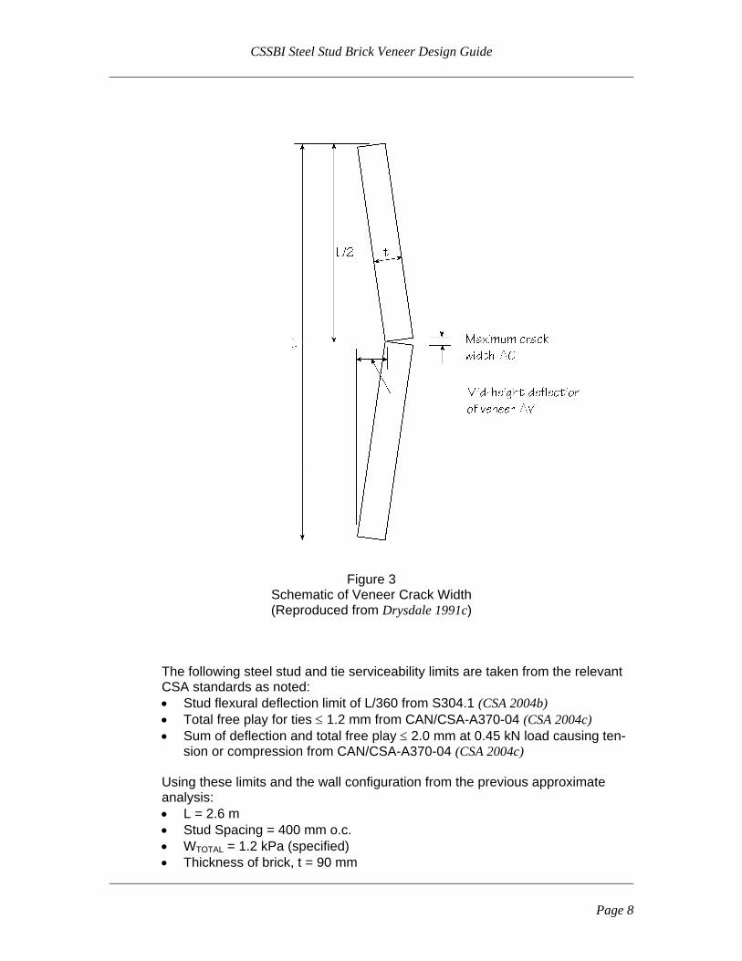
See Figure 3 where the assumed geometry of the midheight flexural crack is
modeled. The brick above and below the triangularly shaped crack is assumed to behave as 2 rigid plates and by similar triangles ΔC is given by:
ΔC = 4(ΔV)(t/L)
Page 7
CSSBI Steel Stud Brick Veneer Design Guide
Figure 3 Schematic of Veneer Crack Width (Reproduced from Drysdale 1991c)
The following steel stud and tie serviceability limits are taken from the relevant
CSA standards as noted: • Stud flexural deflection limit of L/360 from S304.1 (CSA 2004b) • Total free play for ties ≤ 1.2 mm from CAN/CSA-A370-04 (CSA 2004c) • Sum of deflection and total free play ≤ 2.0 mm at 0.45 kN load causing ten-
sion or compression from CAN/CSA-A370-04 (CSA 2004c) Using these limits and the wall configuration from the previous approximate analysis: • L = 2.6 m • Stud Spacing = 400 mm o.c. • W = 1.2 kPa (specified) TOTAL
• Thickness of brick, t = 90 mm
Page 8
CSSBI Steel Stud Brick Veneer Design Guide
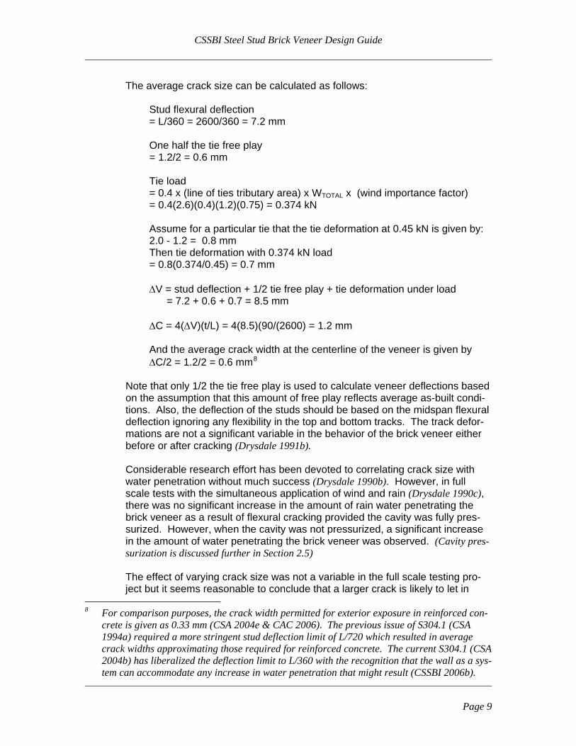
The average crack size can be calculated as follows:
Stud flexural deflection = L/360 = 2600/360 = 7.2 mm One half the tie free play = 1.2/2 = 0.6 mm Tie load = 0.4 x (line of ties tributary area) x WTOTAL x (wind importance factor) = 0.4(2.6)(0.4)(1.2)(0.75) = 0.374 kN Assume for a particular tie that the tie deformation at 0.45 kN is given by: 2.0 - 1.2 = 0.8 mm Then tie deformation with 0.374 kN load = 0.8(0.374/0.45) = 0.7 mm ΔV = stud deflection + 1/2 tie free play + tie deformation under load = 7.2 + 0.6 + 0.7 = 8.5 mm ΔC = 4(ΔV)(t/L) = 4(8.5)(90/(2600) = 1.2 mm And the average crack width at the centerline of the veneer is given by ΔC/2 = 1.2/2 = 0.6 mm8
Note that only 1/2 the tie free play is used to calculate veneer deflections based on the assumption that this amount of free play reflects average as-built condi-tions. Also, the deflection of the studs should be based on the midspan flexural deflection ignoring any flexibility in the top and bottom tracks. The track defor-mations are not a significant variable in the behavior of the brick veneer either before or after cracking (Drysdale 1991b).
Considerable research effort has been devoted to correlating crack size with
water penetration without much success (Drysdale 1990b). However, in full scale tests with the simultaneous application of wind and rain (Drysdale 1990c), there was no significant increase in the amount of rain water penetrating the brick veneer as a result of flexural cracking provided the cavity was fully pres-surized. However, when the cavity was not pressurized, a significant increase in the amount of water penetrating the brick veneer was observed. (Cavity pres-surization is discussed further in Section 2.5)
The effect of varying crack size was not a variable in the full scale testing pro-ject but it seems reasonable to conclude that a larger crack is likely to let in
8 For comparison purposes, the crack width permitted for exterior exposure in reinforced con-
crete is given as 0.33 mm (CSA 2004e & CAC 2006). The previous issue of S304.1 (CSA 1994a) required a more stringent stud deflection limit of L/720 which resulted in average crack widths approximating those required for reinforced concrete. The current S304.1 (CSA 2004b) has liberalized the deflection limit to L/360 with the recognition that the wall as a sys-tem can accommodate any increase in water penetration that might result (CSSBI 2006b).
Page 9
CSSBI Steel Stud Brick Veneer Design Guide
more water under conditions of no or partial cavity pressurization than a smaller crack. If the cavity is fully pressurized, then a larger crack size is likely of little consequence from a water penetration point of view. Refer also the discussion on crack widths in Footnote 8.
2.5 Pressure Equalization and the Rain Screen Design Principle SS/BV walls should be designed as either fully or partially pressurized rain
screen systems. For a detailed description of the rain screen concept, the reader is referred to a number of useful references (Ganguli 1987, Drysdale 1990c, Morrison Hershfield 1990a, Drysdale 1991c, Trestain 1992, Baskaran 1992, Straube 1993, Posey 1996, Trestain 1996 & BIA 27.). A brief description follows.
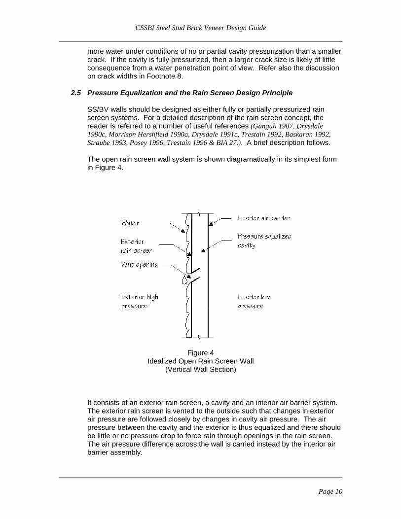
The open rain screen wall system is shown diagramatically in its simplest form in Figure 4.
Figure 4
Idealized Open Rain Screen Wall (Vertical Wall Section)
It consists of an exterior rain screen, a cavity and an interior air barrier system.
The exterior rain screen is vented to the outside such that changes in exterior air pressure are followed closely by changes in cavity air pressure. The air pressure between the cavity and the exterior is thus equalized and there should be little or no pressure drop to force rain through openings in the rain screen. The air pressure difference across the wall is carried instead by the interior air barrier assembly.
Page 10

CSSBI Steel Stud Brick Veneer Design Guide
Advantages
i) The exterior rain screen is not sensitive to imperfections. Any accidental
openings (for example in sealants or mortar joints) are not likely to con-tribute to additional rain penetration since the pressure difference driving the water penetration is eliminated.
ii) There is a second line of defense to water penetration. Water that passes through the exterior rain screen does not bridge the cavity but runs down the inside face of the rain screen to drain out.
iii) The interior air barrier system is protected from the deleterious effects of water, ultraviolet radiation and temperature extremes.
iv) Because the interior air barrier does not get wet, minor air leakage through it will not contribute to water penetration into the interior space.
v) Air circulation in the cavity can assist drying. Disadvantages
i) True pressure equalization requires careful design and construction.
See the discussion that follows:
In order to achieve true pressure equalization, a number of design and construction details require attention: • The vent openings in the rain screen must have adequate area. The
required vent opening size is a function of the volume of the cavity, the air barrier leakage rate, the flexibility of the air barrier assembly and the dynamic nature of wind gusts.
• The air barrier should have a low leakage rate. It is possible to have a pressure equalized wall in combination with an air barrier with a high leakage rate but this would require considerable air flow through the rain screen to supply the make-up air. While the pres-sure equalized principle would not be offended, water penetration through the rain screen could still occur with droplets transported along with the moving air through openings.
• Horizontal air flow in the cavity must be controlled. Horizontal air flow occurs because of variations in wind pressure over the surface of the wall. This variation is most dramatic at corners where positive wind pressure on one wall is always accompanied by negative wind pressure on the adjacent side walls. See Figure 5. This horizontal air flow substantially defeats other efforts to create a pressure equal-ized wall and vertical baffles are required at least at the building cor-ners as illustrated in Figure 6. Some researchers argue for com-plete compartmentalization of the cavity with vertical baffles as fre-quent as 3 metres o.c. Horizontally, baffling provided by shelf angles at every floor level is normally considered adequate. Note that addi-tional horizontal baffling may be required in some locations such as near the top of the building to isolate the wall cavity from the para-pet.
Page 11

CSSBI Steel Stud Brick Veneer Design Guide
Figure 5
Lack of Pressure Equalization Due to Cavity Horizontal Air Flow Plan View of Wall Corner (from Drysdale 1991c)
Figure 6
Corner Air Baffle to Reduce Horizontal Air Flow in Cavity Plan View of Wall Corner
Page 12
CSSBI Steel Stud Brick Veneer Design Guide
Some building scientists have argued that a true open rain screen wall is not practical largely because pressure equalization is difficult to achieve. They have proposed another type of wall, designated the drain screen, which has similar construction details to the rain screen except that no particular effort is made to achieve full pressure equalization. With this design approach, water will penetrate the exterior rain screen and efforts should be focused on insuring it does not bridge the cavity and can be drained out. Many current walls al-though designed as fully pressure equalized rain screens, are probably closer to the drain screen principle for a variety of reasons including leaky air barriers, inadequate vent area and the absence of vertical baffles (especially corner baf-fles) to inhibit horizontal air flow in the cavity. In addition, brick veneer walls may leak water even in the absence of any pressure differential.
One possibility is gravity assisted flow through accidental openings that divert water inwards and downwards. These openings may be present due to con-struction errors or due to post-construction deterioration.
A similar but more pervasive mechanism has been reported by Newman and Whiteside (Newman 1981). In head joints, small downward sloping paths exist in cracks in the mortar to brick interface. These paths fill by gravity or capillary suction when the outside surface of the brick is wet. A hydrostatic driving force (potentially equal to the height of a course of brick – approximately 68 mm of water or 0.7 kPa) is available to drive water into the cavity. They found experi-mental support for this hypothesis by applying a back pressure to the veneer up to the point when leakage stopped. The required back pressure to eliminate leaks varied from 25 to 40 mm of water representing good and bad construction respectively. These hydrostatic heads are equivalent to driving forces of 0.2 to 0.4 kPa which in turn are equivalent to a significant portion of the design wind pressure.
The conclusion is that brick veneer walls leak and they leak more in the pres-
ence of a wind pressure differential. See Figure 7, for a typical SS/BV detail at the floor level which illustrates the
weep holes, vents, shelf angle, water barrier and flashings all of which are fun-damentally important to the successful rain screen and drain screen wall sys-tem. An alternative detail taken from the Brick Veneer Steel Stud Best Practice Guide (Posey 1996) is provided in Figure 8. The relative merits of these two de-tails are discussed in Note 1.
Page 13

CSSBI Steel Stud Brick Veneer Design Guide
Figure 7 Shelf Angle Detail with Insulation in the Stud Space
and Drywall Air Barrier
Page 14

CSSBI Steel Stud Brick Veneer Design Guide
Figure 8 Shelf Angle Detail Without Insulation in the Stud Space
and With Exterior Air Barrier (reproduced from Posey 1996)
Page 15

CSSBI Steel Stud Brick Veneer Design Guide
Note 1 – Figure 7 versus Figure 8 1.1 Rentable Space
Figure 7 is preferred for maximum rentable floor area because insulation in the stud space means less wall thickness for the same R value.
1.2 Structural Efficiency
Figure 7 is generally preferred for structural efficiency. The brick veneer is closer to the face of the building resulting in: • simpler shelf angle details • better tie performance under compressive loads – the brick tie spans across a smaller
gap • simpler structural connections between the steel stud back-up and the windows and
doors and since they are not so far outboard. 1.3 Building Science Efficiency
Figure 8 is generally preferred from a building science perspective. • the dewpoint never falls within the stud space thus eliminating any risk of stud space
moisture accumulation due to condensation • the efficiency of the insulation is not compromised by the thermal bridging through
the steel studs (the presence of the steel studs reduces the effective R value for the in-sulation in the stud space – see CSSBI 2002)
• the shelf angle and slab edge thermal bridge are substantially eliminated (insulation is carried down over the face of the slab and behind the shelf angle).
1.4 Interior versus Exterior Air Barrier
Figure 7 shows an interior drywall air barrier. This type of air barrier has several ad-
vantages. The air barrier can be inspected and maintained over time. It is typically carefully installed since it forms the interior finish. It is not penetrated by brick ties. It is installed on the warm side of the wall free from the deleterious effects of temperature fluctuations and moisture. However, special detailing is required including sealed elec-trical boxes, continuity at intersecting elements and adequate fastening to the studs for the applied loads. Its primary disadvantage is susceptibility to damage by building occu-pants.
Figure 8 shows an exterior air barrier. By installing the air barrier behind the exterior
insulation, it is substantially free of the deleterious effects of temperature fluctuations. In addition, the exterior air barrier is not susceptible to damage by building occupants. Its primary disadvantage is the difficulty of inspection and maintenance over time.
Page 16

CSSBI Steel Stud Brick Veneer Design Guide
2.6 The Interaction Between Air/Vapour Flow, Thermal Performance and Mois-
ture Accumulation
2.6.1 Winter Considerations During the winter months in cold climates9, the exfiltration of warm, hu-
mid interior air through the wall system is a particular concern. If the dewpoint is located within the stud space, condensation will occur at that location and there is the possibility of moisture build-up with its re-sulting deleterious effects on insulation and sheathing material as well as the potential for mold growth and corrosion of metal components.
The movement of air is driven by interior pressurization from mechanical
systems, the stack effect and negative wind pressures. The movement
9 It is difficult to define in abstract terms what constitutes a cold climate. Nearly all of Canada
can be considered cold with the only relevant issue being how cold (and how wet). Local ex-perience may be the best indicator. Refer to Hutcheon 1983 and Straube 2005 for further dis-cussion.
Note 1 – continued 1.5 Venting Options
Figure 8 shows the shelf angle flashing detail carried down to cover the uncaulked hori-
zontal joint in the brick beneath the shelf angle. The uncaulked joint is intended to re-place the need for periodic open head joint vents and the flashing is intended to prevent wind driven rain from penetrating the uncaulked joint. The difficulty is primarily an aes-thetic one –such a large piece of exposed flashing may be subject to unsightly imperfec-tions. Figure 7 shows the more conventional option with the flashing carried down only far enough to form a drip, a caulked joint beneath the shelf angle and periodic head joint vents.
1.6 Other Design Considerations – Figure 7 The risk of condensation in the Figure 7 stud space can be mitigated:
• by providing enough exterior insulation so that the dew point falls outside of the stud space (always or always except a few of the coldest days)
• by insuring adequate drying potential to the outside and by the use of materials that are not moisture sensitive.
The slab thermal bridging in Figure 7 could be improved by continuing the exterior insu-
lation over the face of the slab and over the vertical leg of the shelf angle. However, the thermal bridge through the horizontal leg of the shelf angle will remain.
Page 17

CSSBI Steel Stud Brick Veneer Design Guide
of this air is resisted by the air barrier. See Note 2 for a brief discussion of the difference between an air barrier and a vapour barrier.
In cold climate construction, SS/BV wall systems are typically built with
batt insulation in the stud space and some form of sheathing on the out-side face of the studs plus exterior rigid insulation. Drysdale and Kluge (Drysdale 1990b) studied these types of SS/BV walls in simulated winter conditions (-17° C minimum) with 35 - 40% relative humidity on the warm side (21° C) and a continuous pressure differential (75 Pa) across the wall. They included deliberate imperfections in the air barrier so that the vulnerability of the system to air leakage could be studied. Without exterior insulation they found that both the studs and the inside face of the exterior sheathing were subject to moisture accu-mulation. With 25 mm of rigid polystyrene insulation there was no mois-ture accumulation on either the studs or the inside face of the exterior sheathing. With 25 mm of rigid polystyrene insulation and with higher relative humidity (50 - 55%) on the warm side, condensation was ob-served on the inside face of the exterior sheathing. Refer to the re-search report for more detail.
Without exterior insulation, moisture accumulation and corrosion of the steel parts is more probable. In addition, the quantity of moisture accu-mulating on the exterior sheathing may be excessive – beyond the wet-ting capability of the sheathing and beyond the drying capability of the wall. With exterior insulation (25 mm minimum) condensation on the steel parts can usually be ignored. In this case, the thermal bridging that oc-curs at stud locations is a virtue since they pump heat to the cold side and keep themselves above the dewpoint temperature.
At the simplest level, the potential for condensation between studs can be studied using the classical thermal resistance formula to determine
Note 2 Air barriers are airtight elements that control the flow of air through the wall system. They are the structural element that resists the pressure difference be-tween the interior and exterior air space. Vapour barriers on the other hand are only intended to control the diffusion of water vapour through the wall sys-tem and are subject to very small loads that are of no consequence structurally. Based on field experience, tests and analysis, it can be demonstrated that the mass of water (as vapour) which can be carried into a wall by air leakage is several magnitudes larger than the amount of water that is transmitted through the wall by vapour diffusion (Drysdale 1991c). A possible exception occurs in hot humid exterior conditions when vapour diffusion to the inside of an air con-ditioned building may assume relatively greater importance.
Page 18

CSSBI Steel Stud Brick Veneer Design Guide
temperature at any point in the wall for comparison with the calculated dew point. The resistance formula can be presented as follows:10
tx = ti - (Rx / Rt)(ti - to) where: tx = the temperature at any point in the wall Rx = thermal resistance from the indoor air to any point
in the wall at which the temperature is to be determined.
Rt = overall wall thermal resistance from indoor air to outdoor air
ti = indoor air temperature to = outdoor air temperature
The calculation of the overall wall resistance, Rt, usually excludes the cavity air space and the brick veneer because they are "short-circuited" thermally by circulating air through weepers and vents. Keller (Keller Engineering 1992) found that under some conditions the veneer and the air space might be included in the calculation of Rt.
In any case, moisture accumulation in the stud space should always be
considered as a possibility in design. For cold climates, drying potential for the stud space should be maintained with adequate vapour perme-ability to the outside.
2.6.2 Summer Considerations Note that in much of Canada, cold winters are often accompanied by hot
humid summers. While, winter conditions are typically the most severe with respect to the quantity of moisture accumulation, hot humid sum-mer conditions should not be ignored – the possibility of air infiltration and reverse vapour flow should be considered.
The design problem is essentially the reverse of the winter situation – a
substantial temperature drop exists between the outside and the air conditioned interior space. See Lstiburek 1993, Lstiburek 2001, Lstiburek 2002 and Straube 2001 for further information.
10 Checking the thermal profile through the wall against the dewpoint is a helpful first indicator
of the potential for wetting. However, to better understand the wetting and in particular the drying potential for the wall, more analysis of the transfer of heat, air and moisture is neces-sary. The National Building Code (NRC 2005) requires that "Calculations related to the transfer of heat, air and moisture and the transmission of sound shall conform to good prac-tice such as that described in the ASHRAE handbooks." To this end, a number analytical tools of varying sophistication are available. An overview of these tools and their limitations are provided in Building Science for Building Enclosures, Chapter 14 (Straube 2005).
Page 19
CSSBI Steel Stud Brick Veneer Design Guide
One concern is air leakage from outside to inside driven by interior de-pressurization from mechanical systems, the reverse stack effect and positive wind pressures. The possibility of condensation exists when the incoming air is cooled below the dewpoint within the wall assembly – typically on the back of the interior sheathing. As for winter conditions, an effective air barrier is required.
In addition and unlike the winter case, vapour diffusion can be a signifi-
cant contributor to moisture accumulation in the wall assembly. The po-rous brick veneer absorbs and retains large quantities of water during rainfalls. With subsequent solar heating, the temperature of both the brick and the now saturated air space behind is raised well above the outside ambient air temperature. A large inward vapour pressure drive results and a low permeance vapour retarder is required on the outside of the studs.
However, in a wall optimized for winter performance, the exterior
sheathings on the studs are typically vapour permeable. The high summer vapour drives from outside in can result in moisture accumula-tion in the insulated stud space where air conditioning lowers the tem-perature inside the stud space below the dewpoint. Again, the back of the interior sheathing is the most likely condensation site. In this case, drying potential to the inside of the building is desirable which suggests a moderate permeance interior sheathing and vapour retarder. The low permeance polyethylene vapour retarders that are so common on the inside face of the studs may not be the best choice since they will inhibit drying to the inside.
3. Design Recommendations The following is an overview of relevant design recommendations for SS/BV walls. It is not intended as a comprehensive or exhaustive list. Refer to the relevant building codes and design standards. 3.1 Steel Stud Back-Up System
3.1.1 Steel Studs
• Design the steel stud back-up for the full wind and earthquake load ignoring any structural contribution from the brick veneer (S304.1-04 – CSA 2004b).
Page 20
CSSBI Steel Stud Brick Veneer Design Guide
• Structural design of the steel stud back-up should conform to the re-
quirements of the North American Specification for the Design of Cold-Formed Steel Structural Members, CAN/CSA-S136-01 (CSA 2001a), and its supplement S136S1-04 (CSA 2004a).11 See also CSSBI 2006a for detailed steel stud structural design examples.
• Unless explicitly designed as an axial load bearing system, no axial load other than self-weight should be placed on the steel stud back-up.
• Deflection limit = L/360 (S304.1). • A minimum thickness exclusive of coatings = 1.146 mm. • Minimum corrosion protection = Z180 galvanizing or equivalent. • Maximum spacing of bridging = 1200 mm. The typical recommended
wind bearing stud bridging spacing of 1500 mm has been reduced here to account for the increase in secondary torsion that can occur when studs are loaded through brick ties.
3.1.2 Ties
• For flexible backing12, design ties for wind or earthquake load acting
over a tributary area equal to 40% of the tributary lateral load on a vertical line of ties, but not less than double the tributary lateral load on the tie (unless otherwise calculated by detailed stiffness analysis considering the tie forces before and after cracking of the veneer) (S304.1-04 – CSA 2004b).
• Tie free play and deformation under load is to be determined and limited in accordance with the requirements of CAN/CSA-A370-04 (CSA 2004c). Typically, the tie manufacturer does the necessary analysis and testing to insure conformance with A370.
• For minimum corrosion protection, refer to the requirements in A370-04. A370 specifies tie corrosion protection – hot dipped galvanized after fabrication or stainless steel – as a function of the driving rain index and the height above grade.
• Space ties to conform to the requirements of A370-04 and S304.1-04. S304.1 provides special spacing requirements for studs – ties shall be spaced not more than 820 mm apart horizontally and 600 mm apart vertically. Ties may be staggered when the horizontal stud spacing does not exceed 410 mm o.c. and provided the top row of ties is not staggered. An example of a staggered tie layout is illus-trated in Figure 9 including the design tributary areas for this case. Note that Figure 9 also illustrates the A370 requirements for the top row of ties to be within 300 mm of the top of a veneer panel and within 400 mm of the bottom where the bearing does not provide adequate lateral support. A370 also requires special spacing of ties around openings.
11 At the time of publication, S136-07 (CSA 2007) is available but not referenced in the Na-
tional Building Code. Note that S136-07 includes a number of useful North American sup-plementary standards that specifically address steel stud design issues (AISI 2007a - e).
12 See Footnote 7.
Page 21

CSSBI Steel Stud Brick Veneer Design Guide
• Minimize the projected horizontal area that can act as a platform for the accumulation of mortar droppings. Accumulated mortar droppings can act as a moisture bridge across the air space.
• It is preferred to connect the ties directly to the steel studs without relying on the compressive strength of the exterior sheathing to transfer positive wind loads to the studs. Some exterior sheathings and insulation types do not have adequate long-term compressive strength and stiffness. In any case, if sheathings are part of the load transfer mechanism, they are to be included in the tie testing re-quired by A370.
• For connection of the tie to the stud, it is preferred to avoid sheet metal screws in pull-out in the outside flange of the stud. This type of connection may be susceptible to failure through corrosion and typically has approximately half the strength of a screw in shear.
Figure 9
Staggered Tie Spacing Permitted by S304.1-04 (CSA 2004b)
3.2 Air Barriers and Vapour Retarders
3.2.1 Air Barriers An air barrier must have the following four characteristics:
• Strength to resist the design wind load and the effects of other inter-nal pressures (mechanical pressurization and the stack effect).
Page 22

CSSBI Steel Stud Brick Veneer Design Guide
• Low air flow properties. • Continuity around the building envelope. • Durability to perform for the expected service life of the building. Theoretically, the air barrier can be located on either the warm side or the cold side of the back-up wall. For further discussion, see Note 1 Section 1.4 and Note 2.
3.2.2 Vapour Retarders Vapour retarders should be located on the warm side of the back-up
wall and not on the cold side. As discussed in Note 2, much of the historic difficulty with air and vapour barriers is related to the misunderstanding of the independent functions of the air barrier and vapour retarder. Vapour retarders are intended to control the diffusion of water vapour through materials whereas air barriers are intended to limit the flow of air through the wall. See also Quirouette 1985. It can be difficult to insure that either barrier performs only a single function and a common problem may be that wall assemblies con-tain essentially a double set of barriers resulting in trapped moisture between.
For winter conditions, it is considered good practice to have increasing down-
stream vapour permeability so that any accidental moisture in the stud space is allowed to dry to the outside by diffusion. It is common to place a very imper-meable vapour barrier on the warm side of the stud insulation but a barrier with moderate permeance may be preferred. See Section 2.6.2 for further dis-cussion on this issue. The requirement for analytical study of the transfer of heat, air and moisture is discussed briefly in Footnote 10.
3.3 Exterior Sheathings, Exterior Insulation and Moisture Barriers
3.3.1 Exterior Sheathings Exterior sheathings should be resistant to moisture attack including pos-
sible condensation from inside the stud space and rain water that may breach the brick veneer, air space and moisture barrier. Exterior sheath-ings may also be either a deliberate or accidental air barrier and as a consequence be subjected to significant wind load. Care is also re-quired to insure that the exterior sheathing does not form an accidental air/vapour barrier that inhibits drying out of the back-up wall should there be any moisture accumulation.
3.3.2 Exterior Insulation
Provide a minimum of 25 mm of rigid exterior insulation to: • Control condensation on the stud components and in the stud
space. • Control dust shadowing on the interior finish. • Improve the R value of the wall.
Page 23
CSSBI Steel Stud Brick Veneer Design Guide
More than 25 mm may be required to control condensation within an in-
sulated stud space. See Section 2.6.1 for further discussion.
3.3.3 Moisture Barriers Moisture barriers are intended to shed any water that crosses the air
space. The barrier should have lapped joints to insure that water does not enter the stud space. Appropriate air/vapour permeability is re-quired to allow drying out of the back-up wall should there be any mois-ture accumulation.
3.4 Air Space Size A 1" minimum air space is recommended with 2" preferred.
Small air spaces may result in water crossing the cavity to the back-up wall. Mortar joint bridges, mortar droppings on the ties and accumulated mortar droppings at the bottom of the cavity are all possible paths. Due to construction tolerances, a nominal 1" air space will likely be infringed on in the as-built wall. On the other hand, larger air spaces in combination with larger exterior insulation thicknesses can result in re-duced brick tie compressive strengths and more expensive detailing for windows, doors and shelf angles. See Note 1 Section 1.2 for further discussion.
3.5 Weepers and Vents Provide weepers and vents as required by local building codes but not more
than 800 mm o.c. (CAN/CSA-A371-04 – CSA 2004d) Weepers are required to allow water that penetrates the brick veneer to drain out. They
are also required in combination with vents for pressure equalization of the rain screen cavity. Drysdale and Wilson (Drysdale 1990c) stated that vents and weepers compris-ing open head joints at 800 mm were adequate for pressure equalization. Note that the need for vents is somewhat controversial. In addition to pressure equalization, some building scientist believes they are important for air circulation in the cavity and drying out. Others argue that the extra water they let in is not compensated for by the im-proved drying. In order to minimize water penetration through the vents, they should not be located beneath the weepers above (A371-04). For further discussion pertaining to the venting details in Figures 7 & 8, see Note 1, Section 1.5.
3.6 Other Measures to Control Water Penetration
• For design of masonry elements (bricks, mortar, shelf angles, lintels), refer to the relevant building codes and design standards. In addition, there are other useful resource materials, for example: BIA Technical Notes (BIA) and CMHC guidelines (Drysdale 1991c, Posey 1996 & Malhorta 1998). Provide the necessary horizontal (under the shelf angle) and vertical movement joints
Page 24

CSSBI Steel Stud Brick Veneer Design Guide
weatherproofed with appropriate sealants. Provide well filled head joints and well tooled mortar joints.13
• Provide robust durable flashings with well sealed laps and end dams. Pro-vide a positive slope to the exterior. Do not terminate flashings behind the face of the brick veneer. Install flashings behind the exterior sheathing and/or moisture barrier.
13 S304.1-04 (CSA 2004b) requires the flexural bond strength normal to the bed joints to be not
less than 0.20 MPa. There are qualifications when this provision applies. See Clause 9.1.1.
Page 25
CSSBI Steel Stud Brick Veneer Design Guide
References
(Air-Ins 1988) Air-Ins Inc. June 1988. Air Permeance of Building Materials, for Canada Mortgage and Housing Corporation. (Air-Ins 1991) Air-Ins Inc. September 1991. Airtightness Test on Components Used to Join Different or Similar Materials of the Building Envelope, for Canada Mortgage and Housing Corporation. (AISI 2002a) American Iron and Steel Institute. January 2002. Cold-Formed Steel Fram-ing Design Guide, Design Guide CF02-1. (AISI 2002b) American Iron and Steel Institute. 2002. AISI Manual Cold-Formed Steel Design.
Part I – Dimensions and Properties Part II – Beam Design Part III – Column Design Part IV – Connections Part V – Supplementary Information Part VI – Test Procedures
(AISI 2003) American Iron and Steel Institute. 2003. Steel Stud Brick Veneer Design Guide, Design Guide CF03-1. (AISI 2007a) American Iron and Steel Institute. 2007. North American Standard for Cold-Formed Steel Framing - Wall Stud Design, AISI S211-07. (AISI 2007b) American Iron and Steel Institute. 2007. North American Standard for Cold-Formed Steel Framing - Header Design, AISI S212-07. (AISI 2007c) American Iron and Steel Institute. 2007. North American Standard for Cold-Formed Steel Framing - General Provisions, AISI S200-07. (AISI 2007d) American Iron and Steel Institute. 2007. North American Standard for Cold-Formed Steel Framing - Product data, AISI S201-07. (AISI 2007e) American Iron and Steel Institute. December 2007. Cold-Formed Steel Framing Design Guide, Second Edition, Design Guide D110-07. (Arumala 1982) Arumala, J.O. and Brown,R.H. April 1982. Performance Evaluation of Brick Veneer with Steel Stud Backup, Clemson University, for the Brick Institute of Amer-ica and the Metal Lath/Steel Framing Association. (ASHRAE 2005) American Society of Heating, Refrigerating, and Air-Conditioning Engi-neers. 2005. ASHRAE Handbook – Fundamentals.
Page 26

CSSBI Steel Stud Brick Veneer Design Guide
(ASTM) American Society for Testing and Materials, Special Technical Publications.
(ASTM 1982) Borchelt, G., Editor. 1982. ASTM STP 778, Masonry: Materials, Properties and Performance. (ASTM 1986) Kellermeyer, K.B. and Chin, I.R. 1986. Lessons Learned from In-vestigations of Over 500 Distressed Masonry and Stone Facades, ASTM STP 901, Building Performance, Function, Preservation and Rehabilitation. (ASTM 1990) Schwarz, Thomas A., Editor. October 1990. ASTM STP 1107, Wa-ter in Exterior Building Walls. (ASTM 1991) Ruggiero, S.S. and Myers, J.C. 1991. ASTM STP 1107, Design and Construction of Watertight Exterior Building Walls. (ASTM 1995) Melander, J.M. and Lauersdorf, L.R., Editors. March 1995. ASTM STP 1180, Masonry: Design and Construction, Problems and Repair.
(Baskaran 1992) Baskaran, A. March 1992. Review of Design Guidelines for Pressure Equalized Rainscreen Walls, Institute for Research in Construction Internal Report #629. (BIA) Brick Institute of America Technical Notes on Brick Construction.
(BIA 7) Technical Notes 7 - Water Penetration Resistance - Design and Detailing, December 2005. (BIA 7A) Technical Notes 7A - Water Penetration Resistance - Materials, Decem-ber 2005. (BIA 7B) Technical Notes 7B - Water Penetration Resistance - Construction and Workmanship, December 2005. (BIA 18) Technical Notes 18 - Volume Changes - Analysis and Effects of Move-ment, October 2006. (BIA 18A) Technical Notes 18A - Accommodating Expansion of Brickwork, No-vember 2006. (BIA 27) Technical Notes 27 - Brick Masonry Rain Screen Walls, August 1994. (BIA 28B) Technical Notes 28B - Brick Veneer/Steel Stud Walls, December 2005. (BIA 44B) Technical Notes 44B - Wall Ties for Brick Masonry, May 2003.
(Brown 1995) Brown, W.C. and Ullett, J.M. 1995. Measured Pressure Equalized Per-formance of a Brick Veneer/Steel Stud Assembly, Report 4, for Canada Mortgage and Housing Corporation.
Page 27

CSSBI Steel Stud Brick Veneer Design Guide
(Burnett 1994) Burnett, E.F.P. October 1994. Brick-Veneer/Steel-Stud Project - Task 5, Remedial Tie Systems for BV/SS Walls: Summary Report, Building Engineering Group, University of Waterloo, for Canada Mortgage and Housing Corporation. (CAC 2006) Cement Association of Canada. 2006. Concrete Design Handbook, Third Edition (Canam 1999) Canam Building Envelope Specialists Inc. 1999. Practical Guidelines for Designers, Contractors, and Developers on the Installation of Air Leakage Control Meas-ures in New and Existing High-Rise Commercial Buildings, for Canada Mortgage and Housing Corporation. (CBD) Canadian Building Digest, Institute for Research in Construction, National Re-search Council of Canada.
(CBD 2) Ritchie, T. 1960. CBD 2, Efflorescence. (CBD 40) Garden, G.K. 1963. CBD 40, Rain Penetration and Its Control. (CBD 48) Hutcheon, N.B. 1963. CBD 48 Requirements for Exterior Walls. (CBD 72) Garden, G.K. 1965. CBD 72, Control of Air Leakage is Important. (CBD 170) Sereda, P.J. 1975. CBD 170, Atmospheric Corrosion of Metals. (CBD 175) Latta, J.K. 1976. Vapour Barriers: What are They? Are They Effec-tive?
(Cowie 1990a) Cowie, J.W. February 1990. The Failure of Steel Studs, The Magazine of Masonry Construction. (Cowie 1990b) Cowie, J.W. September 1990. The Failure of Steel Studs, Encon Loss Control Bulletin. (Crise 1972) Crise, D.J. November 1972. Thermal Performance of Walls Framed with Steel Studs with Slit Webs, United States Steel Corporation. (CSA 1994a) Canadian Standards Association. 1994. Masonry Design for Buildings, Limit States Design, S304.1-94. (CSA 1994b) Canadian Standards Association. 1994. Masonry Construction for Build-ings, CAN3-A371-94. (CSA 1995) Canadian Standards Association. 1995. Guideline on Durability in Buildings, S478-95. (CSA 2001a) Canadian Standards Association. 2001. North American Specification for the Design of Cold-Formed Steel Structural Members, CAN/CSA-S136-01. (CSA 2001b) Canadian Standards Association. 2001. Commentary on North American Specification for the Design of Cold-Formed Steel Structural Members, S136.1-01.
Page 28

CSSBI Steel Stud Brick Veneer Design Guide
(CSA 2004a) Canadian Standards Association. 2004. Supplement 2004 to the North American Specification for the Design of Cold-Formed Steel Structural Members (2001 Edition), S136S1-04. (CSA 2004b) Canadian Standards Association. 2004. Design of Masonry Structures, S304.1-04. (CSA 2004c) Canadian Standards Association. 2004. Connectors for Masonry. CAN/CSA-A370-04. (CSA 2004d) Canadian Standards Association. 2004. Masonry Construction for Build-ings, CAN/CSA-A371-04. (CSA 2004e) Canadian Standards Association. 2004. Design of Concrete Structures, CAN/CSA-A23.3-04 (CSA 2007) Canadian Standards Association. 2007. North American Specification for the Design of Cold-Formed Steel Structural Members, S136-07. (CSSBI 1987) Canadian Sheet Steel Building Institute, August 1987. Lightweight Steel Framing Manual. (CSSBI 1991) Canadian Sheet Steel Building Institute. 1991. Lightweight Steel Framing Design Manual. (CSSBI 2002) Canadian Sheet Steel Building Institute. 2002. Lightweight Steel Framing Architectural Design Guide. (CSSBI 2004) Canadian Sheet Steel Building Institute. 2004. Lightweight Steel Framing Wall Stud and Floor Joist Load Tables. (CSSBI 2006a) Canadian Sheet Steel Building Institute. 2006. Lightweight Steel Framing Design Manual, Second Edition. (CSSBI 2006b) Canadian Sheet Steel Building Institute. September 2006. Steel Studs as Back-up for Brick Veneer – Changes in NBC 2005, Technical Bulletin, Volume 7, Num-ber 6. (CSSBI 2008) Canadian Sheet Steel Building Institute. 2008. Guide Specification for Wind bearing Steel Studs, CSSBI S5-08. (Drysdale 1989a) Drysdale, R.G., Keller H. and Suter, G.T. 1989. Seminar on Steel Stud Brick Veneer Wall Systems, for Canada Mortgage and Housing Corporation. (Drysdale 1989b) Drysdale, R.G. and Wilson, J. A. March 1989 Report on Behaviour of Brick Veneer/Steel Stud Tie Systems, McMaster University, for Canada Mortgage and Housing Corporation. (Drysdale 1989c) Drysdale, R.G. and Chidiac, S. May 1989. Defining Better Wall Sys-tems, for Canada Mortgage and Housing Corporation.
Page 29

CSSBI Steel Stud Brick Veneer Design Guide
(Drysdale 1990a) Drysdale, R.G. and Kluge, A. May 1990. Performance of Brick Veneer Steel Stud Wall Systems Subject to Temperature, Air Pressure and Vapour Pressure Differentials, McMaster University, for Canada Mortgage and Housing Corporation. (Drysdale 1990b) Drysdale, R.G., Kluge, A. and Roscoe, P. May 1990. A Report on Wa-ter Leakage Characteristics of Bricks and Brick Assemblages, McMaster University, for Canada Mortgage and Housing Corporation. (Drysdale 1990c) Drysdale, R.G. and Wilson, M. July 1990. Tests of Full Scale Brick Ve-neer Steel Stud Walls to Determine Strength and Rain Penetration Characteristics, McMaster University, for Canada Mortgage and Housing Corporation. (Drysdale 1991a) Drysdale, R.G. March 1991. Construction Problems in Multi-Family Residential Buildings, for Ontario New Home Warranty Plan and Canada Mortgage and Housing Corporation. (Drysdale 1991b) Drysdale, R. G. and Breton N. December 1991. Strength and Stiffness Characteristics of Steel Stud Back-up Walls Designed to Support Brick Veneer. Pre-pared for Project Implementation Division, Canada Mortgage and Housing Corporation. McMaster University. (Drysdale 1991c) Drysdale, R.G. and Suter, G.T. 1991. Exterior Wall Construction in High Rise Buildings, Brick Veneer on Concrete Masonry or Steel Stud Wall Systems, for Can-ada Mortgage and Housing Corporation. (Drysdale 1994) Drysdale, R.G., Hamid, A.A. and Baker, L.R. 1994 Masonry Structures Behaviour and Design, Prentice-Hall. (Drysdale Engineering 1993) Drysdale Engineering and Associates Limited. December 1993. User Reference Manual for a Finite Element Analysis Program for Masonry Ve-neer/Steel Stud Wall Systems, prepared for T.W.J. Trestain Structural Engineering as part of a contract with Canada Mortgage and Housing Corporation. (Fenton 1986a) Fenton, G.A. and Suter, G.T. December 1986. Differential Movements and Stresses in High-Rise Masonry Veneers: Analysis, Canadian Journal of Civil Engi-neering. (Fenton 1986b) Fenton, G.A. and Suter, G.T. December 1986.Differential Movements and Stresses in High-Rise Masonry Veneers: Case Study, Canadian Journal of Civil En-gineering. (Ganguli 1986) Ganguli, U., Lux, M.E., Brown, W.C. and Perreault, J.C. 1986. An Air Bar-rier for the Building Envelope Building Science Insight, National Research Council of Canada. (Ganguli 1987) Ganguli, U. and Dalgliesh, W.A. July 1987. Wind Pressures on Open Rain Screen Walls: Place Air Canada, National Research Council of Canada, Institute for Research in Construction.
Page 30
CSSBI Steel Stud Brick Veneer Design Guide
(Grimm 1989) Grimm, C.T. and Yura, J.A. 1989. Shelf Angles for Masonry Veneer, Jour-nal of the Structural Division, Proceedings of ASCE, Vol. 115, No. 3, pp. 509-525. (Gulay 1993) Gulay, B.W., Stewart, C.D. and Foley, G.J. July 1993. Field Investigation Survey of Air Tightness, Air Movement and Indoor Air Quality in High Rise Buildings, Summary Report, Wardrop Engineering, for Canada Mortgage and Housing Corporation. (Hatzinikolas 1987) Hatzinikolas, M.A., Lee R. and Warwaruk, J. December 1987. Fac-tors Affecting the Performance of Metal Stud Walls Used as a Back-up System to Ma-sonry Veneer, Edmonton: Prairie Research Institute. (Hutcheon 1983) Hutcheon, N.B. and Handegord, G.O.P. 1983. Building Science for a Cold Climate, NRCC, published by Construction Technology Centre Atlantic Inc. (Ife 1977) Ife, L.W. February 1977. Sheet Steel Framing for Residential and Light Con-struction, Technical Bulletin No. 17, The Steel Company of Canada Limited. (Inculet 1996) Inculet, D. and Surry, D. June 1996. The Influence of Unsteady Pressure Gradients on Compartmentalization Requirements for Pressure-Equalized Rainscreens. Canada Mortgage and Housing Corporation. (Keller 1992) Keller, H., Trestain, T.W.J. and Maurenbrecher, A.H.P. March 1992. The Durability of Steel Components in Brick Veneer/Steel Stud Wall Systems, Proceedings, Sixth Conference on Building Science and Technology, Toronto. (Keller 1995) Keller, H. and Trestain, T. W.J. June 1995. Brick Veneer/Steel Stud Walls - A Repair Solution, 7th Canadian Masonry Symposium. (Keller Engineering 1992) Keller Engineering Associates Inc. December 1992. Perform-ance Monitoring of a Brick Veneer/Steel Stud Wall System, for Canada Mortgage and Housing Corporation. (Lstiburek 1993) Lstiburek, Joseph W. November 1993. Humidity Control in the Humid South, J, BETEC Workshop Proceedings. (Lstiburek 2001) Lstiburek, Joseph W. December 2001. Moisture, Building Enclosures, and Mold, Part 1 of 2, , HPAC Engineering. (Lstiburek 2002) Lstiburek, Joseph W. January 2002. Moisture, Building Enclosures, and Mold, Part 2 of 2, by Joseph W. Lstiburek, HPAC Engineering. (Malhorta 1998) Malhorta, A. 1998. Best Practice Guide Flashings, for Canada Mort-gage and Housing Corporation. (McGinley 1985) McGinley, Wararuk, Longworth and Hatzinikolas. May 1985. The Inter-action of Masonry Veneer and Steel Studs in Curtain Wall Construction, Structural Engi-neering Report No. 127, The University of Alberta. (McKay 1993) McKay, M.C., Chevrier, A. and Quirouette, R.L. March 1993. Testing of Air Barrier Construction Details II, Morrison Hershfield Limited, for Canada Mortgage and Housing Corporation.
Page 31

CSSBI Steel Stud Brick Veneer Design Guide
(Morrison Hershfield 1990a) Morrison Hershfield Limited. August 1990. A Study of the Rainscreen Concept Applied to Cladding Systems on Wood Frame Walls, for Canada Mortgage and Housing Corporation. (Morrison Hershfield 1990b) Morrison Hershfield Limited. August 1991. Structural Re-quirements for Air Barriers, for Canada Mortgage and Housing Corporation. (Morrison Hershfield 1990c) Morrison Hershfield Limited. August 1991. CMHC Research Project Testing of Air Barriers Construction Details, for Canada Mortgage and Housing Corporation. (NAHB 1973) NAHB Research Foundation Inc., for American Iron and Steel Institute. No-vember 1973. Status of Cold-Formed Steel Framing in Residential Construction - Ther-mal Performance in Exterior Walls. (Newman 1981) Newman, A.J. and Whiteside, D. 1981. Water and Air Penetration Through Brick Walls - A Theoretical and Experimental Study, Trans. J. Brit. Ceram. Soc., Vol 80. (Newman 1984) Newman, A.J. and Whiteside, D. 1984. Water and Air Penetration Through Masonry Walls - A Device for the Measurement of Air Leakage In-Situ, Brit. Ce-ram. Trans. J., Vol 83. (NRC Updates) Construction Technology Updates, Institute for Research in Construction, National Research Council of Canada.
(Update 9) Chown, G.A., Brown, W.C. and Poirier, G.F. December1997. Evolu-tion of Wall Design for Controlling Rain Penetration, Construction Technology Update No. 9. (Update 17) Rousseau, M.Z., Poirier, G.F. and Brown, W.C. July 1998. Pressure Equalization in Rainscreen Wall Systems, Construction Technology Update No. 17. (Update 23) Maurenbrecher, A.H.P. December 1998. Water Shedding Details Improve Masonry Performance, Construction Technology Update No. 23. (Update 34) Brown, W.C., Chown, G.A., Poirier, G.F. and Rousseau, M.Z. De-cember 1999. Designing Exterior Walls According to the Rainscreen Principle, Construction technology Update No. 34. (Update 41) Kumaran, M.K. and Haysom, J.C. October 2000. Low-Permeance Materials in Building Envelopes, Construction Technology Update No. 41.
(NRC 1995) National Research Council of Canada. 1995. National Building Code of Can-ada 1995. (NRC 2005) National Research Council of Canada. 2005. National Building Code of Can-ada 2005.
Page 32

CSSBI Steel Stud Brick Veneer Design Guide
(NRC 2006) National Research Council of Canada. 2006. User's Guide – NBC 2005 Structural Commentaries. (OAA) OAA Rain Penetration Control Practice Guide, Ontario Association of Architects, published online. (Petrone 1995) Petrone, M.V. July 1995. Rigid Air Barrier Assemblies, Petrone Archi-tects, for Canada Mortgage and Housing Corporation. (Plewes 1983) Plewes, W.G. June 1983. A Perspective on Masonry Serviceability, Pro-ceedings, 3rd Canadian Masonry Symposium, Edmonton. (Posey 1996) Posey, J.B. 1996. Best Practice Guide Brick Veneer Steel Stud, Posey Construction Specifications, for Canada Mortgage and Housing Corporation. (Posthma 1992) Posthma, M.A. and Burnett, E.F.P. July 1992. Brick Veneer/Steel Stud Project Initial Exploratory Study Draft Report (Task 1), Building Engineering Group, Uni-versity of Waterloo, for Canada Mortgage and Housing Corporation. (Posthma 1993) Posthma, M.A. and Burnett, E.F.P. August 1993. Brick Veneer/Steel Stud Project Task 2: Four Remedial Tie Systems for BV/SS Walls - Development and Conformance Testing, Building Engineering Group, University of Waterloo, for Canada Mortgage and Housing Corporation. (Pressnail 1997) Pressnail, K.D., Vollering, B., Handegord, G.O. and Kelk, G.H. May 1997. Protecting Gypsum Sheathing in Insulated Steel-Stud Walls, for Canada Mort-gage and Housing Corporation. (Quirouette 1984) Quirouette, R.L. May 1984. Moisture Sources in Houses, Building Sci-ence Insight 83, Division of Building Research, National Research Council of Canada. (Quirouette 1985) Quirouette, R.L. July 1985. The Difference Between a Vapour Barrier and an Air Barrier, Building Practice Note No. 54, Division of Building Research, National Research Council of Canada. (Quirouette 1986) Quirouette, R.L. November 1986. The Air Barrier, A Misunderstood Element, Construction Canada. (Reginato 1990) Reginato, R. and Handegord, G.A. 1990. A Procedure for Estimating the Moisture Performance of Building Envelopes, TROW Canada. (Shawand 1976) Shawand, C.Y. and Tamara, G.T. 1976. Studies on Exterior Wall Air Tightness and Air Infiltration of Tall Buildings, , ASHRAE Transactions, Vol. 82, Part I. (Straube 1993) Straube, J.F. 1993. The Performance of Wall Systems Screened With Brick Veneer, M.A.Sc. Thesis, University of Waterloo. (Straube 2001) Straube, J.F. December 2001. The Influence of Low-Permeance Vapor Barriers on Roof and Wall Performance, Proc. of Performance of Exterior Envelopes of Whole Building VIII, Clearwater Beach, Florida.
Page 33
CSSBI Steel Stud Brick Veneer Design Guide
(Straube 2005) Straube, J.F. and Burnett, E.F.P. 2005. Building Science for Building En-closures, Building Science Press. (Suter 1986) Suter, G.T., Keller, H. June 1986. The Masonry Veneer Soft Joint Issue in a Historical Context, by, Proceedings, Volume 1, 4th Canadian Masonry Symposium. (Suter Keller 1986) Suter Keller Inc. 1986. Brick Veneer/Steel Stud Wall Design and Con-struction Practices in Canada, for Canada Mortgage and Housing Corporation. (Suter Keller 1989) Suter Keller Inc. November 1989. Field Investigation of Brick Ve-neer/Steel Stud Wall Systems, for Canada Mortgage and Housing Corporation, Ottawa. (Suter Keller 1990) Suter Keller Inc. April 1990. Define the Most Cost-Effective Cladding System in Canada: Results of a Survey, for Canada Mortgage and Housing Corporation. (Trestain 1991) Trestain, T.W.J. June 1991. The Success of Steel Studs, Encon Loss Control Bulletin. (Trestain 1992) Trestain, T.W.J. and Rousseau, J. February 1992. Technics: Steel Stud/Brick Veneer Walls, Progressive Architecture. (Follow-up Discussion June 1992). (Trestain 1996) Trestain, T.W.J. January 1996. Assessment Repair Strategy for Existing Buildings Constructed with Masonry Veneer Steel Stud Walls, for Canada Mortgage and Housing Corporation. (Trow 1989) Trow Inc. December 1989. Criteria for the Air Leakage Characteristics of Building Envelopes: Final Report, for Canada Mortgage and Housing Corporation. (U.S. Army 1992) U.S. Army Corps of Engineers. July 1992. Masonry Veneer/Steel Stud Walls, Engineering Technical Letter 1110-3-439. (U.S. Army 1998) U.S. Army Corps of Engineers. November 1998. Design of Cold-Formed Loadbearing Steel Systems and Masonry Veneer/Steel Stud Walls, Technical Instructions, TI 809-07. (Wegner 1994a) Wegner, C.I. and Burnett, E.F.P. April 1994. Brick-Veneer/Steel-Stud Project, Task 3: Remedial Tie Systems for BV/SS Walls - Post Remediation Perform-ance Considerations, Building Engineering Group, University of Waterloo, for Canada Mortgage and Housing Corporation. (Wegner 1994b) Wegner, C.I. and Burnett, E.F.P. April 1994. Brick-Veneer/Steel-Stud Project, Task 4: Dinal Remedial Tie System for BV/SS Walls - Development and Con-formance Testing, Building Engineering Group, University of Waterloo, for Canada Mort-gage and Housing Corporation. (Wilson 1965) Wilson, A. G. and Garden, G. K. 1965. Moisture Accumulation in Walls due to Air Leakage, by, Division of Building Research Technical Paper No. 227, National Re-search Council of Canada.
Page 34