steering, brake & suspension specialists€¦ · classic performance products, inc....
TRANSCRIPT

Classic Performance Products, Inc. 714.522.2000 | fax 714.522.2500 378 E. Orangethorpe Ave. | Placentia, CA 92870 | www.classicperform.com
Steering, Brake & Suspension Specialists
Rev. 06/03/2016
#6066 Firewall Booster Kit - Instructionsfor 1960-62 & 1963-66 GM Half-Ton Pickups
1. Remove the original master cylinder.
2. Remove the remaining bolt attaching the pedal assembly on the firewall.
3. If new booster unit is pre-assembled, remove the firewall mounting bracket.
4. Mount the firewall adapter plate using the holes marked “A1-A3” in the diagram.
5. Using the firewall adapter plate as a template, drill the four 3/8” holes marked “B” in the diagram into the firewall.
6. Remove the bolt from the hole marked “A3” (nearest fender).
7. Insert firewall boot before installing booster on firewall.
8. Reinstall booster bracket.
9. Bolt the booster in place using the holes marked “B” using the supplied bolts, flat/lock washers, and nuts.
10. Drill an additional hole 1” lower than the original pushrod hole in the brake pedal arm; you must use the 3/8” thick washer between the pedal and the heim joint—thin washer goes beneath the nyloc nut.
11. Verify that there is no preload on the master cylinder prior to completing the job with final brake bleeding.
Continued on next page
Read instructions completely before installing booster assembly; make sure it will fit properly before making any modifications (including painting, powdercoating, or plating), as that will void the warranty. There are three distinct kits – 1960-62, 1960-62 Hydraulic Clutch, and 1963-66 –that are covered in the following instructions. Bench-bleeding your master cylinder, which must be a dual-circuit type (if not purchased with booster bracket), must be done before installing.
1960-62 FIREWALL BRAKE BOOSTER KITS - (STANDARD) #6062BBD, #6062BB2, #6062BB4
1/4″ grade 5 10 lb/ft 1/4″ grade 8 14 lb/ft 5/16″ grade 5 19 lb/ft 5/16″ grade 8 29 lb/ft 3/8″ grade 5 33 lb/ft 3/8″ grade 8 47 lb/ft 7/16″ grade 5 54 lb/ft 7/16″ grade 8 78 lb/ft 1/2″ grade 5 78 lb/ft 1/2″ grade 8 119 lb/ft 9/16″ grade 5 114 lb/ft 9/16″ grade 8 169 lb/ft 5/8″ grade 5 154 lb/ft 5/8″ grade 8 230 lb/ft
GENERAL TORQUE SPECIFICATIONS:
NOTE: With 18” and larger wheels we recommend 1/2” wheel studs. The larger the wheel diameter, the greater the force is on the wheel studs. Please inquire about replacement wheel stud kits available from CPP.
RECOMMENDED PRODUCTS TO ASSIST YOUR INSTALL:
BRAKE BLEEDING SYRINGE
POWER DISC BOOSTER INSTALL KIT
COMBINATION VALVE TOOL
UNIVERSAL BRAKE LINE KIT
#CP0105 - Curved Tip
#PDBI-50 - with 50” hose
#PVTOOL
#SLS-04 - Original material
PLEASE NOTE: The installer needs to make sure that nothing can make contact with a brake hose, caliper, or other brake component at any point through the entire range of steering and suspension movement. The installer also needs to make sure none of the steering or braking components can become bound or jammed at any time through the range of suspension or steering movement.
FIREWALL MOUNTING BRACKET
NEW BOOSTER UNIT
FIREWALL ADAPTERPLATE

Classic Performance Products, Inc. 714.522.2000 | fax 714.522.2500 378 E. Orangethorpe Ave. | Placentia, CA 92870 | www.classicperform.com
Steering, Brake & Suspension Specialists
Rev. 06/03/2016
1960-62 FIREWALL BRAKE BOOSTER KITS - (HYDRAULIC CLUTCH) #MT6062BBD, #MT6062BB2, #MT6062BB4
1. Remove the original brake and clutch master cylinders.
2. If new booster unit is pre-assembled, remove the mounting and firewall brackets from the booster.
3. Mount the firewall adapter plate using the original three bolts.
4. Using the bracket as a guide, drill two 3/8” holes into the firewall nearest the fender; remove bracket when done.
5. Bolt the mounting bracket to the firewall bracket using the countersunk Allen bolts with flat/lock washers and nuts.
6. Reinstall the clutch master and tighten 90° pipe thread fitting.
7. Attach firewall/mounting brackets to firewall using the three original bolts; attach the outer booster bracket to the firewall adapter bracket and firewall using supplied bolts, flat/lock washers, and nuts.
8. Insert firewall boot before installing booster.
9. Install clutch linkage and adjust.
10. Install booster and brake master.
11. Drill an additional hole 1” lower than the original pushrod mounting hole in the brake pedal arm; you must use the 3/8” thick washer between the pedal and the heim joint—thin washer goes beneath the nyloc nut.
12. Verify that there is no preload on both master cylinders prior to completing the job with final brake bleeding.
Continued on next page
THESE 2 HOLES NEED TO BE DRILLED INTO THE FIREWALL NEAREST THE FENDER
MOUNTING BRACKET
COUNTERSUNK ALLEN BOLTS
FIREWALL BRACKET
THESE 3 HOLES WILL MATCH UP TO HOLES IN THE FIREWALL
Classic Performance Products, Inc. 714.522.2000 | fax 714.522.2500 378 E. Orangethorpe Ave. | Placentia, CA 92870 | www.classicperform.com
Steering, Brake & Suspension Specialists
Rev. 06/03/2016
AB
C
D
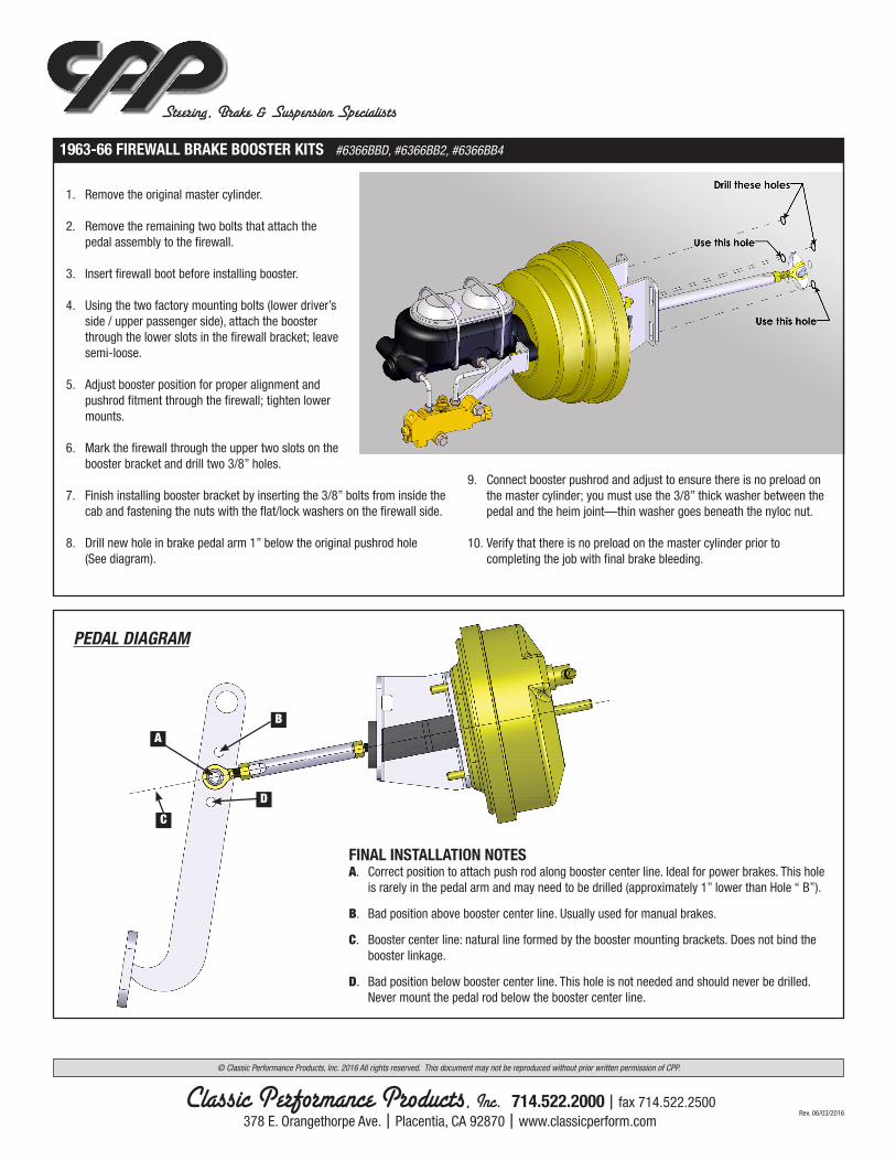
1963-66 FIREWALL BRAKE BOOSTER KITS #6366BBD, #6366BB2, #6366BB4
1. Remove the original master cylinder.
2. Remove the remaining two bolts that attach the pedal assembly to the firewall.
3. Insert firewall boot before installing booster.
4. Using the two factory mounting bolts (lower driver’s side / upper passenger side), attach the booster through the lower slots in the firewall bracket; leave semi-loose.
5. Adjust booster position for proper alignment and pushrod fitment through the firewall; tighten lower mounts.
6. Mark the firewall through the upper two slots on the booster bracket and drill two 3/8” holes.
7. Finish installing booster bracket by inserting the 3/8” bolts from inside the cab and fastening the nuts with the flat/lock washers on the firewall side.
8. Drill new hole in brake pedal arm 1” below the original pushrod hole (See diagram).
9. Connect booster pushrod and adjust to ensure there is no preload on the master cylinder; you must use the 3/8” thick washer between the pedal and the heim joint—thin washer goes beneath the nyloc nut.
10. Verify that there is no preload on the master cylinder prior to completing the job with final brake bleeding.
FINAL INSTALLATION NOTES A. Correct position to attach push rod along booster center line. Ideal for power brakes. This hole
is rarely in the pedal arm and may need to be drilled (approximately 1” lower than Hole “ B”).
B. Bad position above booster center line. Usually used for manual brakes.
C. Booster center line: natural line formed by the booster mounting brackets. Does not bind the booster linkage.
D. Bad position below booster center line. This hole is not needed and should never be drilled. Never mount the pedal rod below the booster center line.
© Classic Performance Products, Inc. 2016 All rights reserved. This document may not be reproduced without prior written permission of CPP.
PEDAL DIAGRAM