stelia aerospace north america - · pdf filethis document and all information contained herein...
TRANSCRIPT
This document and all information contained herein is the sole property of STELIA Aerospace. This document shall not be
reproduced or disclosed to a third party without the express written consent of STELIA Aerospace.
STELIA AEROSPACE
NORTH AMERICA
SPACE QUALIFIABLE BONDED JOINTS
BETWEEN CARBON FIBER
REINFORCED POLYMER (CFRP) AND
ALUMINUM
SOHEILA MAHDAVI
This document and all information contained herein is the sole property of STELIA Aerospace. This document shall not be
reproduced or disclosed to a third party without the express written consent of STELIA Aerospace.
Outline
2
1• Stelia Presentation
2
• Carbon Fiber Reinforced Polymer Composites (CFRP)
3• Objective
4• Requirements specification
5• Qualification Tests
6• Manufacturing and testing of Prototypes
7• Conclusion

This document and all information contained herein is the sole property of STELIA Aerospace. This document shall not be
reproduced or disclosed to a third party without the express written consent of STELIA Aerospace.
STELIA Worldwide
> 6,400 employees
$ 2,5 billion revenue
$ 210 million R&D
N°1 in Europe
for aerostructure
N°3 worldwide
for first and business
class seats
N°1 worldwide
crew seats
N°3 worldwide
for aerostructure
STELIA Group, an aerospace multi-specialist3

This document and all information contained herein is the sole property of STELIA Aerospace. This document shall not be
reproduced or disclosed to a third party without the express written consent of STELIA Aerospace.
• 6,400 employees
– 4,600 in France
with 3 main production sites & 600 in engineering
– 1,000 in North Africa
– 600 in North America
– 5 fully owned Airbus subsidiaries
Commercial deskManufacturing
STELIA Group, a global presence
4

This document and all information contained herein is the sole property of STELIA Aerospace. This document shall not be
reproduced or disclosed to a third party without the express written consent of STELIA Aerospace.
5
STELIA North AmericaLunenburg Facility
Composite ManufacturingMirabel Facility-
Assembly and Systems installation
Mirabel Facility Composite Manufacturing

This document and all information contained herein is the sole property of STELIA Aerospace. This document shall not be
reproduced or disclosed to a third party without the express written consent of STELIA Aerospace.
• Design and build
• Plug & Fly (includes systems)
• Supply chain management optimization
BOMBARDIER Global 7000 / 8000
6
This document and all information contained herein is the sole property of STELIA Aerospace. This document shall not be
reproduced or disclosed to a third party without the express written consent of STELIA Aerospace.
The Competitive Challenge• The Space and Aerospace Industry are directed more heavily than in the
recent past towards:
> new materials;
> lower prices;
> faster manufacturing cycles
> production innovation
• The challenge for Stelia to grow its market share is to develop innovative
manufacturing techniques that are consistent with existing and future
customer demands.
• The challenge is not only from a technology standpoint but also from a
financial standpoint in:
> people,
> Time
> willingness to invest in R&D.
7

This document and all information contained herein is the sole property of STELIA Aerospace. This document shall not be
reproduced or disclosed to a third party without the express written consent of STELIA Aerospace.
Carbon Fiber Reinforced Polymer
Composites (CFRP)
• Advantages:
– High strength
– Light weight
– Dimensional stability under large temperature variations
• Challenges:
– rarely form the totality of the structure and still need to be assembled with metallic parts:
> Titanium
– thermally stable under a large range of temperature
– expensive
– more complex to manufacture
> Aluminum
– commonly used metallic parts for space applications
– CTE completely differs from CFRP’s
» dimensional issues under the influence of a varying temperature
8
This document and all information contained herein is the sole property of STELIA Aerospace. This document shall not be
reproduced or disclosed to a third party without the express written consent of STELIA Aerospace.
Project Objective
9
Select adhesives and associated bonding processes
To bond Carbon Fiber Reinforced Polymer (CFRP) and aluminum
For the Canadian Space Agency (CSA)

This document and all information contained herein is the sole property of STELIA Aerospace. This document shall not be
reproduced or disclosed to a third party without the express written consent of STELIA Aerospace.
Requirements specification
• Phase I:
– Literature review
– Selection, identification and analysis of adhesives
> <1.0% TML (Total Mass Loss)
> <0.1% CVCM (Collected Volatile condensable Material)
> < 10% bonding strength and stiffness variation at -170 ˚C < T <160 ˚C
– Design and fabrication of test coupons for characterization of the
adhesives and bonding processes
– Test the coupons to measure and characterize the bonding strength
and stiffness over the specified temperature range.
10

This document and all information contained herein is the sole property of STELIA Aerospace. This document shall not be
reproduced or disclosed to a third party without the express written consent of STELIA Aerospace.
Requirements specification
• Phase II:
• Bonded joint prototype development and qualification
– Design three CFRP-aluminum on a
> CFRP plate
> CFRP strut
> CFRP tube
– Development of bonding procedure
– Procurement/manufacturing of the prototypes
– Thermal-vacuum (T-Vac) testing of each prototype and verify its bonding
– Random vibration testing to test the bonds
11
This document and all information contained herein is the sole property of STELIA Aerospace. This document shall not be
reproduced or disclosed to a third party without the express written consent of STELIA Aerospace.
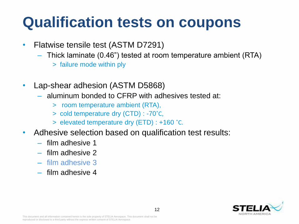
Qualification tests on coupons
• Flatwise tensile test (ASTM D7291)
– Thick laminate (0.46”) tested at room temperature ambient (RTA)
> failure mode within ply
• Lap-shear adhesion (ASTM D5868)
– aluminum bonded to CFRP with adhesives tested at:
> room temperature ambient (RTA),
> cold temperature dry (CTD) : -70˚C,
> elevated temperature dry (ETD) : +160 ˚C.
• Adhesive selection based on qualification test results:
– film adhesive 1
– film adhesive 2
– film adhesive 3
– film adhesive 4
12

This document and all information contained herein is the sole property of STELIA Aerospace. This document shall not be
reproduced or disclosed to a third party without the express written consent of STELIA Aerospace.
Manufacturing of the prototypesPrototype 1: aluminum part bonded on a flat CFRP plate
13
Use G10 sheets to avoid bagging under the mass and around the standoff during curing in the autoclave
Prototype 1 (consisting of 16 plies cured in OA )
Standoffs after curing Broken standoff
This document and all information contained herein is the sole property of STELIA Aerospace. This document shall not be
reproduced or disclosed to a third party without the express written consent of STELIA Aerospace.
14
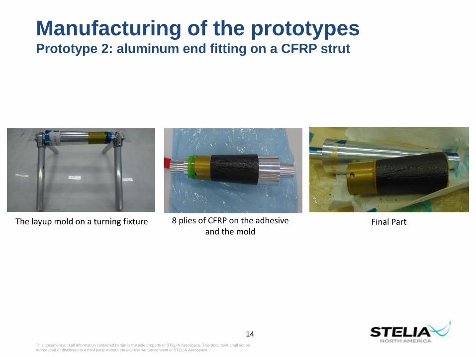
Manufacturing of the prototypesPrototype 2: aluminum end fitting on a CFRP strut
The layup mold on a turning fixture 8 plies of CFRP on the adhesive and the mold
Final Part

This document and all information contained herein is the sole property of STELIA Aerospace. This document shall not be
reproduced or disclosed to a third party without the express written consent of STELIA Aerospace.
15
Manufacturing of the prototypesPrototype 3: aluminum end-fitting on a CFRP tube
A mold is required for manufacturing a tube
out of composites
The mold-fixture with the endfitting,Two layers of adhesive 3 on the end fitting,Sixteen layers of CFRP on the adhesive and the mold.
Final Part

This document and all information contained herein is the sole property of STELIA Aerospace. This document shall not be
reproduced or disclosed to a third party without the express written consent of STELIA Aerospace.
Prototypes testing
• T-Vac testing
– Vacuum test at 0.00005 Tor
– Thermal cycling
> Number of cycles: 10 cycles
> Temperature range -160°C to +140°C
> Tolerances: Cold: -10°C, +0°C / Hot: -0°C, +5°C
> Minimum time at plateau: 30 minutes
> Maximum rate of change: 10°C/min.
– Three prototypes are placed on a solid
aluminum plate inside the chamber.
16

This document and all information contained herein is the sole property of STELIA Aerospace. This document shall not be
reproduced or disclosed to a third party without the express written consent of STELIA Aerospace.
Inspection after TVAC test
• After TVAC, a visual inspection of three prototypes is performed.
• There is no apparent damage in the CFRP or the bondline for
prototype 1. Prototype 1 passed the test.
• One standoff seems to be weakened due to stress concentration.
17

This document and all information contained herein is the sole property of STELIA Aerospace. This document shall not be
reproduced or disclosed to a third party without the express written consent of STELIA Aerospace.
Inspection after TVAC test (Cont.)
• For prototype 2: there was no apparent damage in the CFRP or the
bondline.
• Prototype 2 passed the test.
18

This document and all information contained herein is the sole property of STELIA Aerospace. This document shall not be
reproduced or disclosed to a third party without the express written consent of STELIA Aerospace.
Inspection after TVAC test (Cont.)
• For prototype 3:
– there was no apparent damage in the CFRP or the bondline from the
outside.
– Debonding observed from the insdie.
• Prototype 3 failed the test.
19

This document and all information contained herein is the sole property of STELIA Aerospace. This document shall not be
reproduced or disclosed to a third party without the express written consent of STELIA Aerospace.
Random vibration
20
• Tests were performed at DFL:
– 40,000 lbf capacity shaker
– 150 GRMS acceleration limit
– 37,000 lb force limit
– Mass of slip table is 593.2 lb
– Test plan:

This document and all information contained herein is the sole property of STELIA Aerospace. This document shall not be
reproduced or disclosed to a third party without the express written consent of STELIA Aerospace.
21
Random vibration
Prototype 1: Two stand-offs broke during adhesive cure
Prototype 2 Prototype 3

This document and all information contained herein is the sole property of STELIA Aerospace. This document shall not be
reproduced or disclosed to a third party without the express written consent of STELIA Aerospace.
Random vibration
22
• Prototype 3
– Evidence of failure in adhesive

This document and all information contained herein is the sole property of STELIA Aerospace. This document shall not be
reproduced or disclosed to a third party without the express written consent of STELIA Aerospace.
Random vibration
• Results summary
23

This document and all information contained herein is the sole property of STELIA Aerospace. This document shall not be
reproduced or disclosed to a third party without the express written consent of STELIA Aerospace.
Conclusion
24
• Three prototypes were design and manufactured.
• Co-curing endfitting with adhesive 3 and prepreg was successful.
• Prototypes 1 and 2 passed the TVAC test.
• Prototype 3 failed the TVAC test.
• Random vibration test for prototype 1 is not conclusive:
– Standoff failed before reaching 50% load level.
• Prototype 2 passed random vibration test.
• Random vibration for prototype 3 is not conclusive.
– There was initial failure in the bondline after TVAC.
• Adhesive 3 can be used for bonding aluminum to CFRP for space
application:
– The successful application will depend on the bondline size.
– There is a critical bondline size/surface area above which thermal
stresses cause failure in the bondline.

This document and all information contained herein is the sole property of STELIA Aerospace. This document shall not be
reproduced or disclosed to a third party without the express written consent of STELIA Aerospace.
Thank You
25

This document and all information contained herein is the sole property of STELIA Aerospace. This document shall not be
reproduced or disclosed to a third party without the express written consent of STELIA Aerospace.
Preselection of adhesives
• pre-selected film adhesives to be tested during Phase I:
– film adhesive 1
– film adhesive 2
– film adhesive 3
– film adhesive 4
• The CFRP laminates:
– quasi-isotropic layup
– Plain weave fabric
– Resin: Toughened epoxy
26

This document and all information contained herein is the sole property of STELIA Aerospace. This document shall not be
reproduced or disclosed to a third party without the express written consent of STELIA Aerospace.
Flatwise tensile strength
• Flatwise tensile strength per ASTM D7291.
• Coupon dimensions: D=1” thickness 0.1”.
• Flatwise tensile results:
– Three coupons: 4257 psi, 4287 psi, and 4651 psi.
29-MAR-17CSA – PT9 - CAL-15-101 27

This document and all information contained herein is the sole property of STELIA Aerospace. This document shall not be
reproduced or disclosed to a third party without the express written consent of STELIA Aerospace.
Assessment of results
• Materials set validation:
– FW tensile strength: min of 4257 psi > 2500 psi -> Pass.
– Lap-shear strength: min of 3548.6 psi > 2000 psi -> Pass.
• Inspection of CFRP aluminum joint prototypes:
– Prototype 1: Pass (Not conclusive).
– Prototype 2: Pass.
– Prototype 3: Fail.
29-MAR-17CSA – PT9 - CAL-15-101 28

This document and all information contained herein is the sole property of STELIA Aerospace. This document shall not be
reproduced or disclosed to a third party without the express written consent of STELIA Aerospace.
Random vibration
29
• Prototype 1
– Two stand-offs broke during adhesive cure

This document and all information contained herein is the sole property of STELIA Aerospace. This document shall not be
reproduced or disclosed to a third party without the express written consent of STELIA Aerospace.
Random vibration
30
• Prototype 2
– Vibration test setup

This document and all information contained herein is the sole property of STELIA Aerospace. This document shall not be
reproduced or disclosed to a third party without the express written consent of STELIA Aerospace.
Random vibration
31
• Prototype 2
– Vibration test setup

This document and all information contained herein is the sole property of STELIA Aerospace. This document shall not be
reproduced or disclosed to a third party without the express written consent of STELIA Aerospace.
Random vibration
32
• Prototype 3
– Vibration test setup

This document and all information contained herein is the sole property of STELIA Aerospace. This document shall not be
reproduced or disclosed to a third party without the express written consent of STELIA Aerospace.
Random vibration
33
• Prototype 3
– Vibration test setup

This document and all information contained herein is the sole property of STELIA Aerospace. This document shall not be
reproduced or disclosed to a third party without the express written consent of STELIA Aerospace.
Design, analysis and R&D in advance composite structures
Long term partnership with NRC. NRC co-located with Stelia in Mirabel
Automated Fiber Placement
Manufacturing Space structures
Clean Room 8,000 sqft, Class 100,000
Autoclave 6 feet diameter x 20 feet long
Reticulation Machine 56x96
Mirabel Facility+ 35,000 sqft
34