stol - zenith aircraft company · stol ch750 zenith aircraft company ... this manual has been...
TRANSCRIPT

STOL CH750
Zenith Aircraft Company www.zenithair.com
Bubble Door Installation Section 75-ZA-6 A, Page 1 of 16
Revision 1.1 (08/28/15) © 2010 Zenith Aircraft Co.
Section 75-ZA-6 A Bubble Door Installation
This manual has been prepared for installation of the Bubble Doors. This photo assembly manual is intended as a supplement to the drawings. If there is any discrepancy between this manual and the drawings, the drawings supersede this manual. For more information on building standards and allowable tolerances see “Construction Standards for Zenair Light Aircraft” available from Zenith Aircraft Co.

STOL CH750
Zenith Aircraft Company www.zenithair.com
Bubble Door Installation Section 75-ZA-6 A, Page 2 of 16
Revision 1.1 (08/28/15) © 2010 Zenith Aircraft Co.
Draw a center line on the top of the Doubler Strip.
P/N: 75F12-3 Doubler Strip
Mark a rivet location 17mm forward of the bend and 17mm aft of the front edge in the Doubler Strip. Layout evenly spaced rivet locations at approximately pitch 30mm.

STOL CH750
Zenith Aircraft Company www.zenithair.com
Bubble Door Installation Section 75-ZA-6 A, Page 3 of 16
Revision 1.1 (08/28/15) © 2010 Zenith Aircraft Co.
Mark a rivet location 10mm from the bends on the longer portion of the Doubler Strip. Evenly layout rivet locations at approximately pitch 30mm.
Mark a rivet location 17mm from the bend in the short section of the Doubler Strip. Mark a rivet location 10mm from the end and one half way between the marks.

STOL CH750
Zenith Aircraft Company www.zenithair.com
Bubble Door Installation Section 75-ZA-6 A, Page 4 of 16
Revision 1.1 (08/28/15) © 2010 Zenith Aircraft Co.
Set the Doubler Strip even with the edges of the Cabin Side. Set the back against the Side Channel and Clamp the Doubler Strip to the Longerons on the Cabin Side. Use a #40 drill bit to drill through the Doubler Strip into the Longerons and cleco. Expand the holes in steps to a #20 drill bit and cleco.
Deburr the holes in the Doubler Strip and Longerons, cleco, and rivet the Doubler Strip to the Cabin Side.

STOL CH750
Zenith Aircraft Company www.zenithair.com
Bubble Door Installation Section 75-ZA-6 A, Page 5 of 16
Revision 1.1 (08/28/15) © 2010 Zenith Aircraft Co.
P/N: 75Z1-8 Door Hinge
Set the Hinge against the Rear Wing Attachment and the Door Sill. Mark the Hinge at the Windshield Side Trim.

STOL CH750
Zenith Aircraft Company www.zenithair.com
Bubble Door Installation Section 75-ZA-6 A, Page 6 of 16
Revision 1.1 (08/28/15) © 2010 Zenith Aircraft Co.
Remove the Pin from the Hinge. Cut the Hinge to length at the line marked in the previous step. Mark the flange center line on the Hinge with the barrel up. Mark a rivet location 10mm from each end of the Hinge. Evenly space rivet locations at approximately pitch 40mm. Use a #40 drill bit to drill the rivet location on both halves of the hinge.
Position the Hinge with the barrel up and outside of the Door Sill. Use a #40 drill bit to back drill through the Hinge into the Door Sill and cleco. Use a #30 drill bit to expand the holes and cleco.

STOL CH750
Zenith Aircraft Company www.zenithair.com
Bubble Door Installation Section 75-ZA-6 A, Page 7 of 16
Revision 1.1 (08/28/15) © 2010 Zenith Aircraft Co.
Install the second half of the Hinge. Make sure the Pin is pushed all the way to the front edge of the Hinge. Mark a point approximately 3mm aft of the edge of the Hinge on the Pin.
Bend the Pin 90 degrees at the mark. The Pin is stainless steel and the easiest way to bend it is in a vise with a hammer. Set the mark at the top of the jaws on the vice. Tap the Pin with a hammer until its bent 90 degrees. Then reassemble the Hinge.

STOL CH750
Zenith Aircraft Company www.zenithair.com
Bubble Door Installation Section 75-ZA-6 A, Page 8 of 16
Revision 1.1 (08/28/15) © 2010 Zenith Aircraft Co.
Position the Bubble Door on the Fuselage.
P/N: 75Z1-7 Bubble Door
There should be a roughly even gap between the Fuselage and the stiffening tube on the Door.
STOL CH750
Zenith Aircraft Company www.zenithair.com
Bubble Door Installation Section 75-ZA-6 A, Page 9 of 16
Revision 1.1 (08/28/15) © 2010 Zenith Aircraft Co.
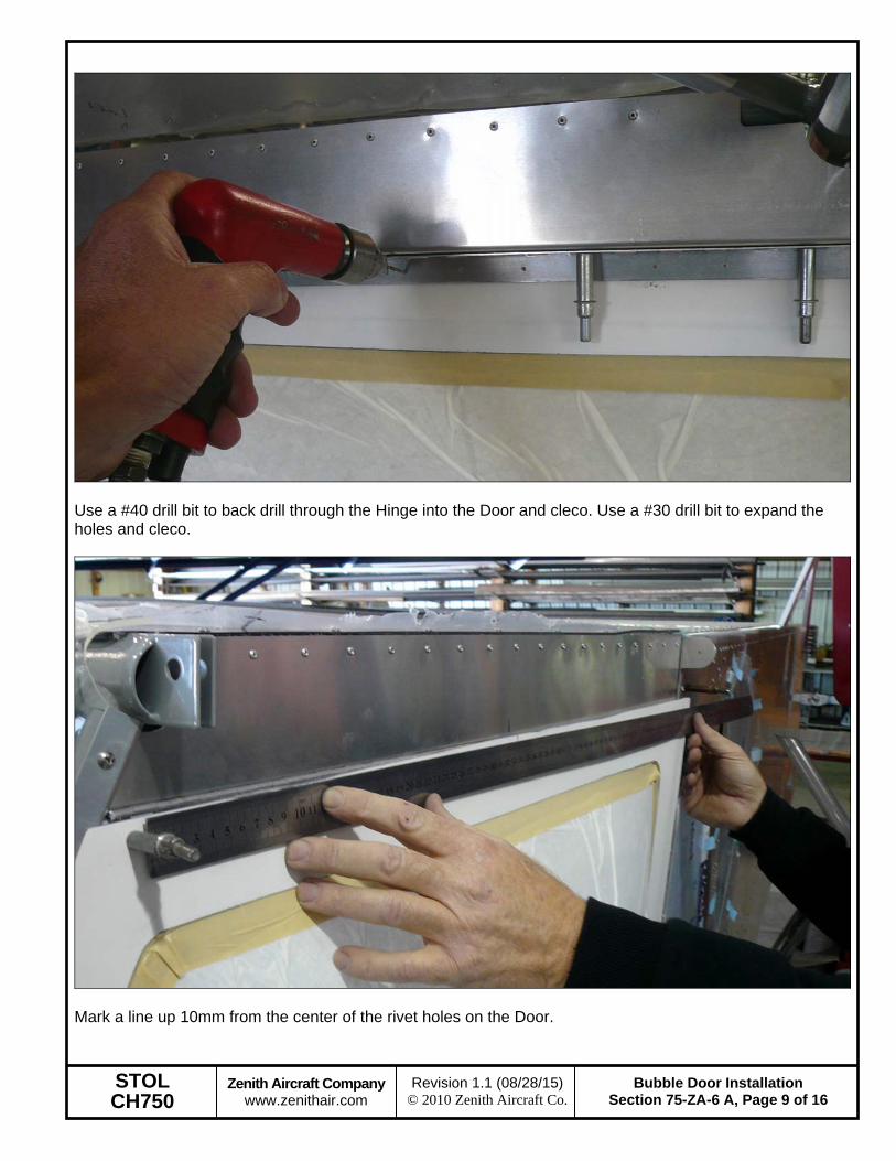
Use a #40 drill bit to back drill through the Hinge into the Door and cleco. Use a #30 drill bit to expand the holes and cleco.
Mark a line up 10mm from the center of the rivet holes on the Door.

STOL CH750
Zenith Aircraft Company www.zenithair.com
Bubble Door Installation Section 75-ZA-6 A, Page 10 of 16
Revision 1.1 (08/28/15) © 2010 Zenith Aircraft Co.
Mark the aft edge of the Windshield Side Trim along the front edge of the Door.
Mark the bottom edge of the Windshield Side Trim on the Door.

STOL CH750
Zenith Aircraft Company www.zenithair.com
Bubble Door Installation Section 75-ZA-6 A, Page 11 of 16
Revision 1.1 (08/28/15) © 2010 Zenith Aircraft Co.
Remove the Door from the Fuselage. Use an angle grinder with a cutoff wheel to trim the Door on the lines. Cut along the line to remove the excess fiberglass from the top of the Door. Cut along the line at the front of the Door up to the mark for the bottom of the Windshield Side Trim. Notch the Door to match the Windshield Side Trim.
Reinstall the Door on the Fuselage. If needed, file the edges to better fit the Fuselage.

STOL CH750
Zenith Aircraft Company www.zenithair.com
Bubble Door Installation Section 75-ZA-6 A, Page 12 of 16
Revision 1.1 (08/28/15) © 2010 Zenith Aircraft Co.
Draw a center line on one flange of the Striker Angle. Layout rivet locations 10mm from each end and one half way between. With a #40 drill bit, drill the rivet locations in the Striker Angle.
P/N: 75Z1-9 Striker Angle
Position the Striker Angle against the Cabin Frame Gusset. Use a #40 drill bit to back drill through the Striker Angle into the Longeron and cleco. Expand the holes to #20 in steps and cleco. Deburr the holes and rivet.

STOL CH750
Zenith Aircraft Company www.zenithair.com
Bubble Door Installation Section 75-ZA-6 A, Page 13 of 16
Revision 1.1 (08/28/15) © 2010 Zenith Aircraft Co.
Mark a line 125mm down from the edge of the fiberglass on the bottom front corner of the Door.
Mark a line 125mm from the edge of the fiberglass on the bottom front corner of the Door. Use a #20 drill bit to drill the intersection of the lines.

STOL CH750
Zenith Aircraft Company www.zenithair.com
Bubble Door Installation Section 75-ZA-6 A, Page 14 of 16
Revision 1.1 (08/28/15) © 2010 Zenith Aircraft Co.
Enlarge the #20 hole to 13/16”. A step drill was used in the photo above.
Position the Exterior Handle on the Door. Trace around the Handle and mark the center on the Handle’s mounting plate.
P/N: 1226A62 Exterior Handle
STOL CH750
Zenith Aircraft Company www.zenithair.com
Bubble Door Installation Section 75-ZA-6 A, Page 15 of 16
Revision 1.1 (08/28/15) © 2010 Zenith Aircraft Co.
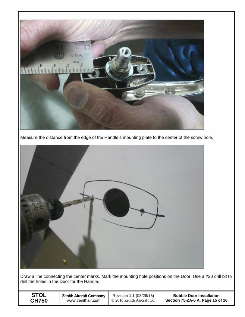
Measure the distance from the edge of the Handle’s mounting plate to the center of the screw hole.
Draw a line connecting the center marks. Mark the mounting hole positions on the Door. Use a #20 drill bit to drill the holes in the Door for the Handle.
STOL CH750
Zenith Aircraft Company www.zenithair.com
Bubble Door Installation Section 75-ZA-6 A, Page 16 of 16
Revision 1.1 (08/28/15) © 2010 Zenith Aircraft Co.
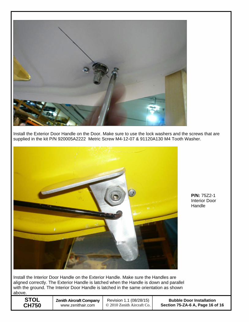
Install the Exterior Door Handle on the Door. Make sure to use the lock washers and the screws that are supplied in the kit P/N 920005A2222 Metric Screw M4-12-07 & 91120A130 M4 Tooth Washer.
Install the Interior Door Handle on the Exterior Handle. Make sure the Handles are aligned correctly. The Exterior Handle is latched when the Handle is down and parallel with the ground. The Interior Door Handle is latched in the same orientation as shown above.
P/N: 75Z2-1 Interior Door Handle