stonelock network user manual version 17.2 · pdf filestonelock network user manual version...
TRANSCRIPT

STONELOCK NETWORK USER MANUAL Version 17.2.1
www.stonelock.com
About StoneLock Pro ................................................................4
1.0 Overview1.01 ..................System Introduction .........................................4
1.02 .................System Components ........................................4
1.03 ................. Installation ........................................................5-6
1.04.................Uninstall .................................................................6
2.0 Instructions for Use 2.01 .................System Startup ............................................. 7-10
2.02 ................System Settings .................................................11
2.03 ................Role Management .............................................11
2.04................Operator Management ...................................12
2.05 ................System Configuration ............................... 13-14
2.06 ................Operation Log ....................................................15
2.07 ................Database Management ..................................16
2.08 ................Device Settings..................................................17
2.09 ................Device Management ........................................18
2.10 .................Device Maintenance .........................................21
2.11 ..................Data Synchronization .....................................22
2.12 .................Electronic Map ..................................................23
2.13 ................. Real-Time Records Management ...............24
2.14 .................User Management ...........................................25
2.15 .................Time Group Management .............................26
2.16 .................Holiday Management .....................................27
2.17 .................Permission Management ..............................27
2.18 .................User Management ....................................28-29
2.19 .................Batch Modify User .......................................... 30
2.20 ................Group Management .................................. 31-32
2.21 .................Data Management ...........................................33
2.22 ................Verification Records Management ............33
2.23 ................Alarm Records Management ......................33
Table of Contents

NETWORK USER MANUAL – www.stonelock.com 2
1.0
About StoneLock Pro
StoneLock Pro is an extremely fast and
accurate IR facial recognition biometric unit
for access control applications. It incorporates
proprietary biometrics along with a keypad
and HID® iClass SE Multi-Class Reader into a
3-point device.
StoneLock Pro™ includes a faceplate unit and
a control unit.
StoneLock Global is a provider of high
quality biometric products for access control
applications.
Section 1: Overview
The StoneLock Network (SLN) software is a security management platform for managing StoneLock
access controls and related systems across a network.
Functions include StoneLock hardware management, user management, privilege management, remote
user enrollment, records checking and alarm controls.
1.01 SYSTEM INTRODUCTION
The SLN software platform integrates StoneLock’s advanced face recognition technology, the access
control functions, along with keypad entries and/or ID cards in various authentication combination
modes.
The SLN software platform centralizes data management, allowing the unique advantages of face
recognition to be quickly pushed across an entire facility, or even multiple facilities, each with multiple
entrance locations. Events can be easily monitored, greatly improving the level of security control.
The SLN platform, allows for control of all access control terminals, including StoneLock units, user
information, user privilege management, records management, system alarm controls and other
functions.
1.02 SYSTEM COMPONENTS
•!StoneLock Network Software Platform
•!StoneLock Pro Access Control Device (up to 64 units on one network)
StoneLock Pro
Faceplate
StoneLock Pro
Control Unit
10:36:2307/17/2013 Wednesday
www.stonelock .com
Cameras(NIR Camera
not visible)
NIR Lights
Light Bar
LCD Display
Keypad
Light Sensor
HIDCardReader

NETWORK USER MANUAL – www.stonelock.com3
1.0
1.03 INSTALLATION
Follow these steps to install the full security management platform software (SLN):
1) Double-click the installer to begin the installation.
2) On the Welcome interface, select [Next] to continue the installation (Figure 1.03-1).
3) At the License Agreement screen (Figure 1.03-2), check the box “I have read and agree to the above
agreement”, and then select [Next] to continue the installation.
4) At the “Choose Install Location” screen (Figure 1.03-3), the system default installation
directory is: C: \ Program Files \ SLN2.3
a. Select [Next] to continue the installation.
b. If you need to modify the installation path, select the [Browse] button to
select the installation folder.
Fig 1.03-1
Fig 1.03-2
Fig 1.03-3
NETWORK USER MANUAL – www.stonelock.com 4
1.0
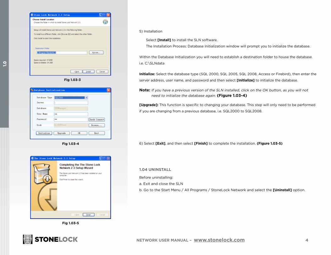
5) Installation
Select [Install] to install the SLN software.
The Installation Process: Database Initialization window will prompt you to initialize the database.
Within the Database Initialization you will need to establish a destination folder to house the database.
i.e. C:\SLNdata
Initialize: Select the database type (SQL 2000, SQL 2005, SQL 2008, Access or Firebird), then enter the
server address, user name, and password and then select [Initialize] to initialize the database.
Note: If you have a previous version of the SLN installed, click on the OK button, as you will not need to initialize the database again. (Figure 1.03-4)
[Upgrade]: This function is specific to changing your database. This step will only need to be performed
if you are changing from a previous database, i.e. SQL2000 to SQL2008.
6) Select [Exit], and then select [Finish] to complete the installation. (Figure 1.03-5)
1.04 UNINSTALL
Before uninstalling:
a. Exit and close the SLN
b. Go to the Start Menu / All Programs / StoneLock Network and select the [Uninstall] option.
Fig 1.03-4
Fig 1.03-5
Fig 1.03-3
1.0
5
2.0
NETWORK USER MANUAL – www.stonelock.com
Section 2: Instructions for Use
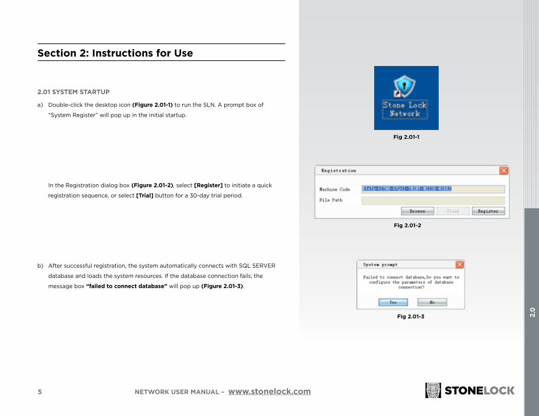
2.01 SYSTEM STARTUP
a) Double-click the desktop icon (Figure 2.01-1) to run the SLN. A prompt box of
“System Register” will pop up in the initial startup.
In the Registration dialog box (Figure 2.01-2), select [Register] to initiate a quick
registration sequence, or select [Trial] button for a 30-day trial period.
b) After successful registration, the system automatically connects with SQL SERVER
database and loads the system resources. If the database connection fails, the
message box “failed to connect database” will pop up (Figure 2.01-3).
Fig 2.01-1
Fig 2.01-3
Fig 2.01-2

6
2.0
NETWORK USER MANUAL – www.stonelock.com
Click [Yes] to pop up the database initialization window (Figure 2.01-3), and then configure relevant
parameters according to actual situation.
Database Type: The system supports SQL Server 2000, 2005, 2008, MS Access, Firebird.
Server: Fill the LAN server rooted by SLN (ie the database server) with actual IP address.
User Name, Password: database type for SQL Server 2000, 2005, 2008; users fill out the SQL Server, the
user name and password usually sa; for Access, the user name and password are empty; for the Firebird,
the user Name Fill sysdba, password is masterkey.
c) When the database connection is successful, the system login interface will appear
(Figure 2.01-5).
Fig 2.01-3
Fig 2.01-4
Fig 2.01-5
7
2.0
NETWORK USER MANUAL – www.stonelock.com
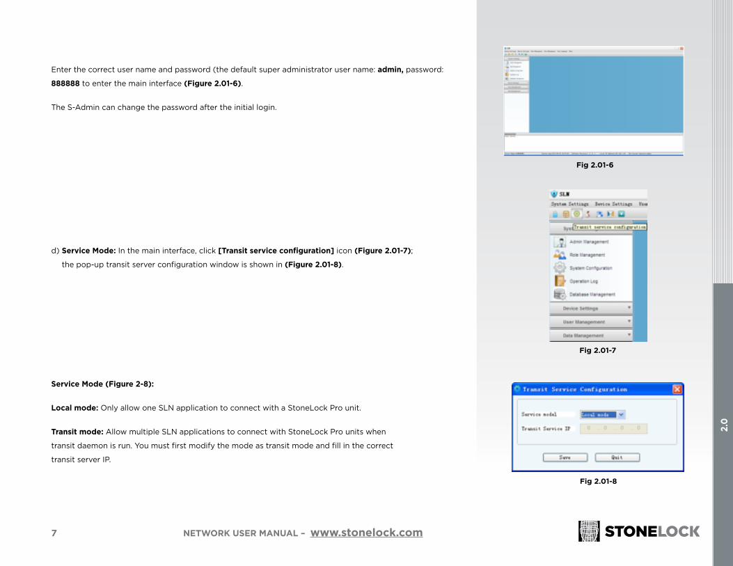
Enter the correct user name and password (the default super administrator user name: admin, password:
888888 to enter the main interface (Figure 2.01-6).
The S-Admin can change the password after the initial login.
d) Service Mode: In the main interface, click [Transit service configuration] icon (Figure 2.01-7);
the pop-up transit server configuration window is shown in (Figure 2.01-8).
Service Mode (Figure 2-8):
Local mode: Only allow one SLN application to connect with a StoneLock Pro unit.
Transit mode: Allow multiple SLN applications to connect with StoneLock Pro units when
transit daemon is run. You must first modify the mode as transit mode and fill in the correct
transit server IP.
Fig 2.01-6
Fig 2.01-7
Fig 2.01-8
8
2.0
NETWORK USER MANUAL – www.stonelock.com
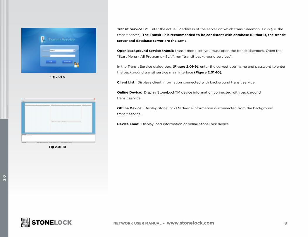
Transit Service IP: Enter the actual IP address of the server on which transit daemon is run (i.e. the
transit server). The Transit IP is recommended to be consistent with database IP; that is, the transit
server and database server are the same.
Open background service transit: transit mode set, you must open the transit daemons. Open the
“Start Menu - All Programs - SLN”; run “transit background services”.
In the Transit Service dialog box, (Figure 2.01-9), enter the correct user name and password to enter
the background transit service main interface (Figure 2.01-10).
Client List: Displays client information connected with background transit service.
Online Device: Display StoneLockTM device information connected with background
transit service.
Offline Device: Display StoneLockTM device information disconnected from the background
transit service.
Device Load: Display load information of online StoneLock device.
Fig 2.01-9
Fig 2.01-10

9
2.0
NETWORK USER MANUAL – www.stonelock.com
2.02 SYSTEM SETTINGS
Click the [System Settings] menu, and it will appear in a menu bar (Figure 2.02-1).
2.03 ROLE MANAGEMENT
See Interface (Figure 2.03-1)
New Role Permissions: Select [New]; the system adds a new role.
New: Click the [New] button to add a new role with a default name. Select desired
Function Module and Details for the role. Choose a name for the Role.
Note: Checking [Enabled] within the Function Module and/or within the Details
section selects all permissions.
Note: Once any permission within a role has been changed, the administrator
roles must be reassigned to the Operator.
SELECT [SAVE] FOR ANY CHANGES TO TAKE PLACE.
Fig 2.02-1
Fig 2.03-1

10
2.0
NETWORK USER MANUAL – www.stonelock.com
2.04 OPERATOR MANAGEMENT
See Interface (Figure 2.04-1)
Add: Click the [Add] button to add a system operator. The name will default to i.e. Oper #. This Operator
will default to the initial password of 888888 until it is changed by the super admin.
Set the new Operator’s user name, password, assign a role and area of privilege.
Click [Save] button.
Reset Password: Choose an Operator; click the [Reset password] button to reset the password back to
default 888888.
Remote Password: This password will be used for remote log-ins. This password can be reset at any time by
the administrator logging in the system.
Single Use: Checking this indicates that the remote password becomes invalid following a single use. This
password can only be reset by the administrator.
Advanced Settings: Select an operator; click the [Advanced Settings] button to set this operator’s mobile-
phone number, address and other details. (Figure 2.04-2)
Note: Admin is the system’s super Administrator. The Admin’s privileges can not be deleted or modified. They can manage all SLN features as well as all StoneLock Pro units within the system. A non-admin operator
can only manage the terminals within their assigned roles and area.
Tip: Passwords may contain 0-16 characters (including letters, numbers, special characters and spaces), and
are not case-sensitive.
Fig 2.04-1
Fig 2.04-2
11
2.0
NETWORK USER MANUAL – www.stonelock.com
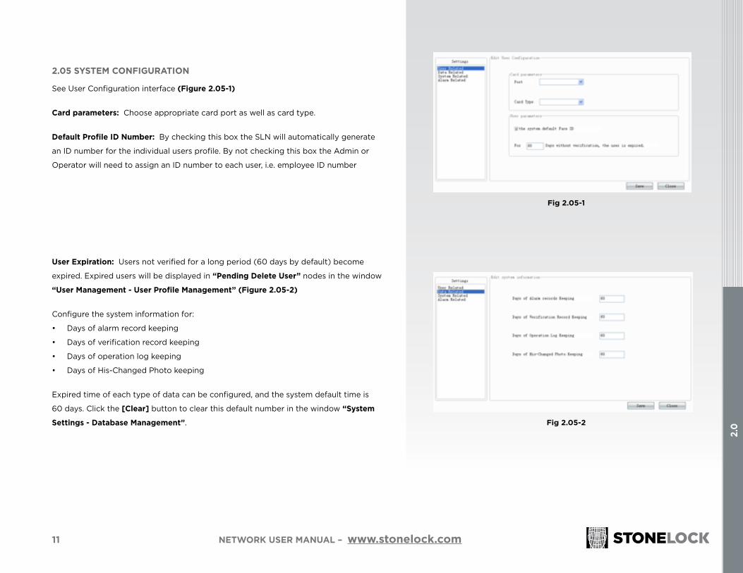
2.05 SYSTEM CONFIGURATION
See User Configuration interface (Figure 2.05-1)
Card parameters: Choose appropriate card port as well as card type.
Default Profile ID Number: By checking this box the SLN will automatically generate
an ID number for the individual users profile. By not checking this box the Admin or
Operator will need to assign an ID number to each user, i.e. employee ID number
User Expiration: Users not verified for a long period (60 days by default) become
expired. Expired users will be displayed in “Pending Delete User” nodes in the window
“User Management - User Profile Management” (Figure 2.05-2)
Configure the system information for:
• Days of alarm record keeping
• Days of verification record keeping
• Days of operation log keeping
• Days of His-Changed Photo keeping
Expired time of each type of data can be configured, and the system default time is
60 days. Click the [Clear] button to clear this default number in the window “System
Settings - Database Management”.
Fig 2.05-1
Fig 2.05-2
12
2.0
NETWORK USER MANUAL – www.stonelock.com
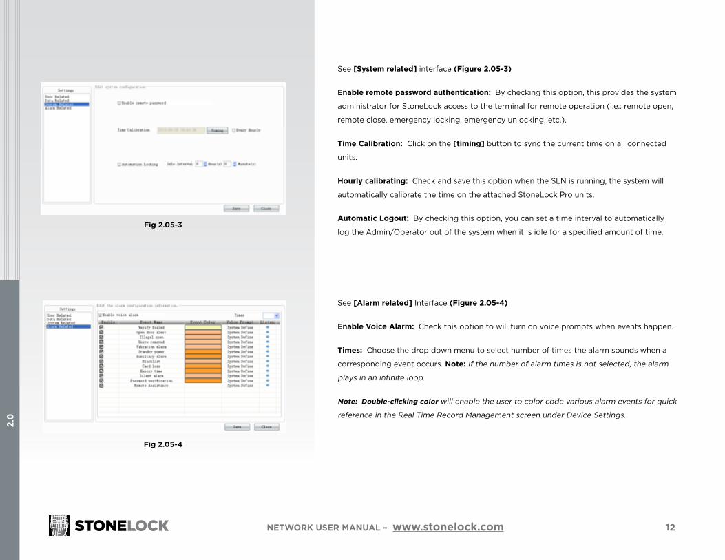
See [System related] interface (Figure 2.05-3)
Enable remote password authentication: By checking this option, this provides the system
administrator for StoneLock access to the terminal for remote operation (i.e.: remote open,
remote close, emergency locking, emergency unlocking, etc.).
Time Calibration: Click on the [timing] button to sync the current time on all connected
units.
Hourly calibrating: Check and save this option when the SLN is running, the system will
automatically calibrate the time on the attached StoneLock Pro units.
Automatic Logout: By checking this option, you can set a time interval to automatically
log the Admin/Operator out of the system when it is idle for a specified amount of time.
See [Alarm related] Interface (Figure 2.05-4)
Enable Voice Alarm: Check this option to will turn on voice prompts when events happen.
Times: Choose the drop down menu to select number of times the alarm sounds when a
corresponding event occurs. Note: If the number of alarm times is not selected, the alarm
plays in an infinite loop.
Note: Double-clicking color will enable the user to color code various alarm events for quick
reference in the Real Time Record Management screen under Device Settings.
Fig 2.05-3
Fig 2.05-4

13
2.0
NETWORK USER MANUAL – www.stonelock.com
2.06 OPERATION LOG
See Interface (Figure 2.06-1)
• Click the drop down in the Operator field to select the Operator.
• Click the drop down in the Start Date to choose the start date.
• Click the drop down in the End Date to choose the end date.
• In the Operation field, type keyword(s) to search events (optional).
• Click the [Search] button; the system will search the selected operator’s entire activity log.
The log information includes: time of event, the operation, the operator, and the server name.
Fig 2.06-1

14
2.0
NETWORK USER MANUAL – www.stonelock.com
2.07 DATABASE MANAGEMENT
See Interface (Figure 2.07-1)
1) Data Cleanup
Click the [Clear] button to delete any expired records based on the set number of days
in the Data Related fields under System Configuration.
Note: Expired data should be cleared periodically to maintain optimal data storage.
2) Database Backup
Click the [Browse] button to specify the storage directory of the database
backup files.
Click the [Backup] button, database backup files labeled with current system time will
be generated immediately and stored in the specified path.
3) Database Restore
Click the [Browse] button to select a backup database file from specified directory.
Click the [Restore] button to restore the database immediately.
Note: Restore will overwrite the existing data with the data in the backup file chosen.
Fig 2.07-1
15
2.0
NETWORK USER MANUAL – www.stonelock.com
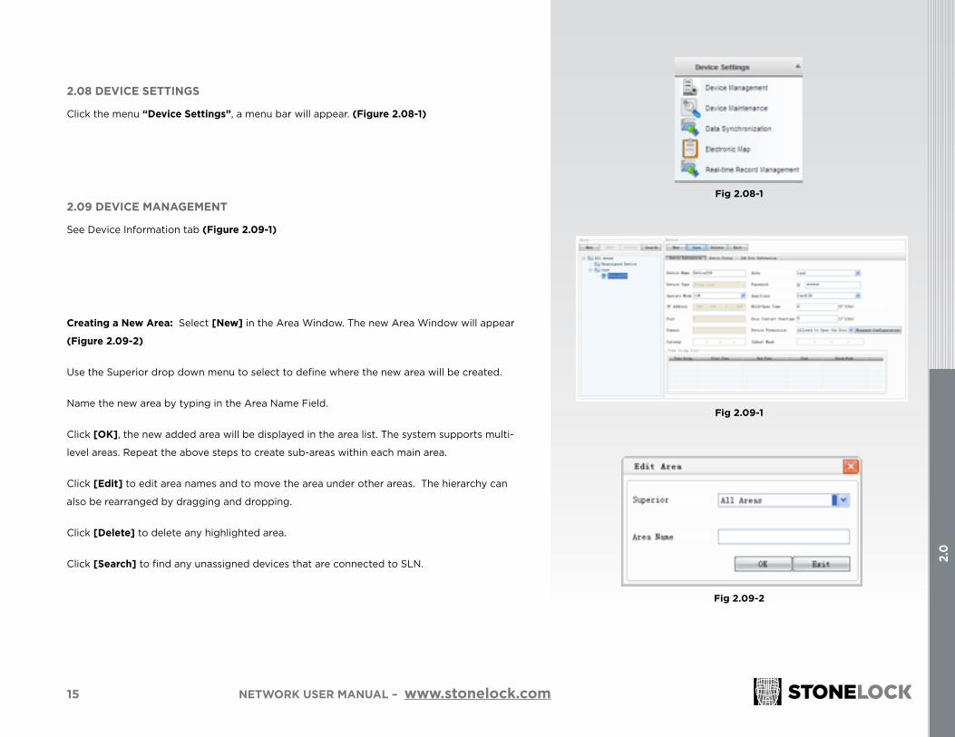
2.08 DEVICE SETTINGS
Click the menu “Device Settings”, a menu bar will appear. (Figure 2.08-1)
2.09 DEVICE MANAGEMENT
See Device Information tab (Figure 2.09-1)
Creating a New Area: Select [New] in the Area Window. The new Area Window will appear
(Figure 2.09-2)
Use the Superior drop down menu to select to define where the new area will be created.
Name the new area by typing in the Area Name Field.
Click [OK], the new added area will be displayed in the area list. The system supports multi-
level areas. Repeat the above steps to create sub-areas within each main area.
Click [Edit] to edit area names and to move the area under other areas. The hierarchy can
also be rearranged by dragging and dropping.
Click [Delete] to delete any highlighted area.
Click [Search] to find any unassigned devices that are connected to SLN.
Fig 2.08-1
Fig 2.09-1
Fig 2.09-2

16
2.0
NETWORK USER MANUAL – www.stonelock.com
Setting up a new device within an area: Select an area and click the [New] button on the device window to
add a device. In the Device Information tab you may:
• name the device
• confirm the device is in the correct area
• select operate mode
• Secondary identity verification (i.e. a card or code)
• IP address of the connected unit
• Choose Hold-Open Time for the controlled door
• Door Contact Over-Time
• Click the [Save] button
Super Password: The Super Password can only be used to open the door in particular situations by the
S-Admin. Check the “validate Super Password” option, the StoneLock Pro unit will validate the super
password (or else invalidate). A Super Password can contain from 4-8 digits.
Operation Modes:
1:1 mode: When this mode is set, users are required to present a card or input an employee number first at a
StoneLock Pro unit, then accept face recognition authentication.
1:N mode: When this mode is set, users can use face only at a StoneLock Pro unit.
Mixed mode:
Caution: Mixed mode should only be established via the SLN. Don’t say we didn’t warn you!
When Mixed mode is selected, the network administrator can allow select individual users to be
authenticated with face only. All other users default to card plus face. (Refer to 2.18 to learn how to set a user
to Mixed mode)
Note: In Mixed mode, a maximum of 200 users can be registered with face-only on a single StoneLock Pro
device. All others users must be card plus face in this same device.
Card verification: Users directly swipe authorized IC \ ID card for authentication.
Fig 2.09-2

17
2.0
NETWORK USER MANUAL – www.stonelock.com
Auxiliary:
Empty: Allows no assisted verification in specified operating mode. This will default the device to is face only.
Card Verification: Allow cards verification in specified operating mode.
ID Verification: Allow employee ID# verification in specified operating mode.
Card Verification/ID Verification: Allows both cards verification and employee ID# verification in specified operating mode.
Device IP: Device IP is set as the actual IP address of StoneLock device. It connects with its corresponding devices when SLN is successfully
connected via network.
1There is a bug in the setup, which allows a non-card-registered S-Admins to establish Mixed Mode and thereby “fatally” lock everyone out of all advanced functions (the only fix for this is to reset the unit with SLN software). Until we get this bug corrected we recommend only Mixed Mode from an SLN. Yes, it happened to us. Yes, StoneLock is very secure.
Note: To identify the corresponding devices ID, a Super Admin must authenticate themselves at a terminal, go the Network, click OK, scroll down to IP settings, click OK and the IP address is shown. To change the IP address click OK and enter the number using the arrow keys will allow you to navigate from field to field, click OK, Esc, Esc.
Device permissions: Configure the open permission for StoneLock device
Allow: Unauthorized users are allowed to open the door after successfully being verified by the StoneLock access device.
Refuse: Unauthorized users are not allowed to open the door after successfully being verified by the StoneLock Pro unit.
18
2.0
NETWORK USER MANUAL – www.stonelock.com
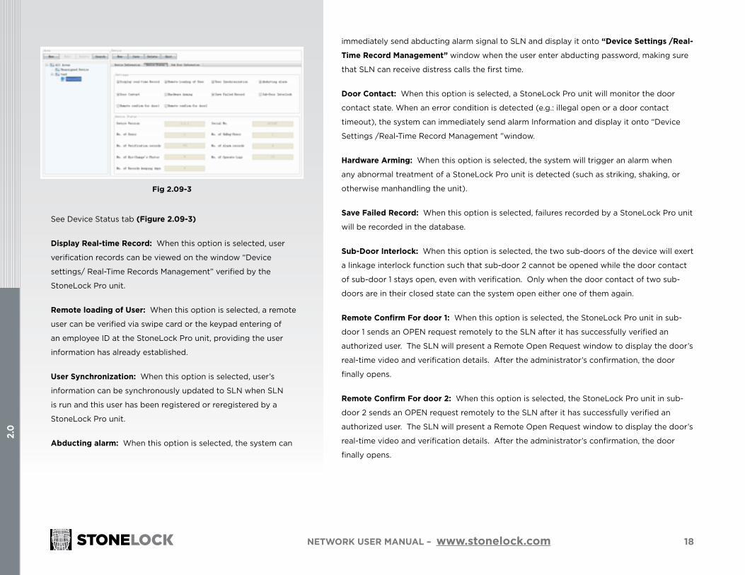
See Device Status tab (Figure 2.09-3)
Display Real-time Record: When this option is selected, user
verification records can be viewed on the window “Device
settings/ Real-Time Records Management” verified by the
StoneLock Pro unit.
Remote loading of User: When this option is selected, a remote
user can be verified via swipe card or the keypad entering of
an employee ID at the StoneLock Pro unit, providing the user
information has already established.
User Synchronization: When this option is selected, user’s
information can be synchronously updated to SLN when SLN
is run and this user has been registered or reregistered by a
StoneLock Pro unit.
Abducting alarm: When this option is selected, the system can
Fig 2.09-3
immediately send abducting alarm signal to SLN and display it onto “Device Settings /Real-
Time Record Management” window when the user enter abducting password, making sure
that SLN can receive distress calls the first time.
Door Contact: When this option is selected, a StoneLock Pro unit will monitor the door
contact state. When an error condition is detected (e.g.: illegal open or a door contact
timeout), the system can immediately send alarm Information and display it onto “Device
Settings /Real-Time Record Management ”window.
Hardware Arming: When this option is selected, the system will trigger an alarm when
any abnormal treatment of a StoneLock Pro unit is detected (such as striking, shaking, or
otherwise manhandling the unit).
Save Failed Record: When this option is selected, failures recorded by a StoneLock Pro unit
will be recorded in the database.
Sub-Door Interlock: When this option is selected, the two sub-doors of the device will exert
a linkage interlock function such that sub-door 2 cannot be opened while the door contact
of sub-door 1 stays open, even with verification. Only when the door contact of two sub-
doors are in their closed state can the system open either one of them again.
Remote Confirm For door 1: When this option is selected, the StoneLock Pro unit in sub-
door 1 sends an OPEN request remotely to the SLN after it has successfully verified an
authorized user. The SLN will present a Remote Open Request window to display the door’s
real-time video and verification details. After the administrator’s confirmation, the door
finally opens.
Remote Confirm For door 2: When this option is selected, the StoneLock Pro unit in sub-
door 2 sends an OPEN request remotely to the SLN after it has successfully verified an
authorized user. The SLN will present a Remote Open Request window to display the door’s
real-time video and verification details. After the administrator’s confirmation, the door
finally opens.

19
2.0
NETWORK USER MANUAL – www.stonelock.com
See Sub Door Information Tab page (Figure 2.09-4)
Remote Open Door: You can open the selected sub-door of StoneLock Pro unit remotely.
Remote Close Door: You can close the selected sub-door of StoneLock Pro unit remotely.
Emergency Unlocking: When this option is selected, the selected Sub-Door of this device stays
open until the administrator selects Normalization (same function as in Device Maintenance).
Emergency Locking: When selected, the selected Sub-Door of this device stays closed until the
administrator selects Normalization (same function as Device Maintenance).
Recover normal: When selected, the door of this device reverts back to normal operation from
emergency locking or emergency unlocking. This function is the same as Normalization in Device
Maintenance.
2.10 DEVICE MAINTENANCE
See Device Maintenance tab (Figure 2.10-1)
Upgrade: Click the [Browse] button to select the upgrade file path and then select the device
expected to be updated in the device list, click the [Upgrade] button to upgrade the device.
Reboot: reboot the specified StoneLock Pro unit remotely.
Format: When selected, all the data in the specified device will be formatted to factory settings.
Warning: All profiles in the device will be cleared.
Emergency Unlocking: When selected, the door of this device stays open until the administrator
chooses Normalization (same function as in Sub-Door Information tab).
Emergency Locking: When selected, the door of this device stays closed until the administrator
chooses Normalization (same function as in Sub-Door Information tab).
Normalization: When selected, the door of this device reverts back to normal operation
from emergency locking or emergency unlocking (same function as in Sub-Door
Information tab).
Fig 2.09-4
Fig 2.10-1

20
2.0
NETWORK USER MANUAL – www.stonelock.com
2.11 DATA SYNCHRONIZATION
See Interface (Figure 2.11-1)
Automatic Synchronization: Check this option to configure the automatic sync cycle and
time to automatically push and pull information to all networked StoneLock devices. Click
[Save].
Manual Synchronization: Choose the device from the Device list on the right, the content
you want to synchronize, and then select [Synchronize]. The chosen device and its content
will be made available within the SLN.
Time group: This function allows synchronizing information for a designated time group for
a specified StoneLock Pro unit.
Holiday: Synchronizes holiday time for a specified StoneLock Pro unit.
User Data: Synchronizes user data for a specified StoneLock Pro unit.
Permissions: Synchronizes permissions for a specified StoneLock Pro unit.
Verification Records: Downloads all verification records from the specified StoneLock Pro
units to the SLN.
Alarm Records: Downloads all alarm records from the specified StoneLock Pro unit to the
SLN.
Note: The system can only perform the data synchronization functions when the chosen StoneLock Pro units are online.
Fig 2.11-1
21
2.0
NETWORK USER MANUAL – www.stonelock.com
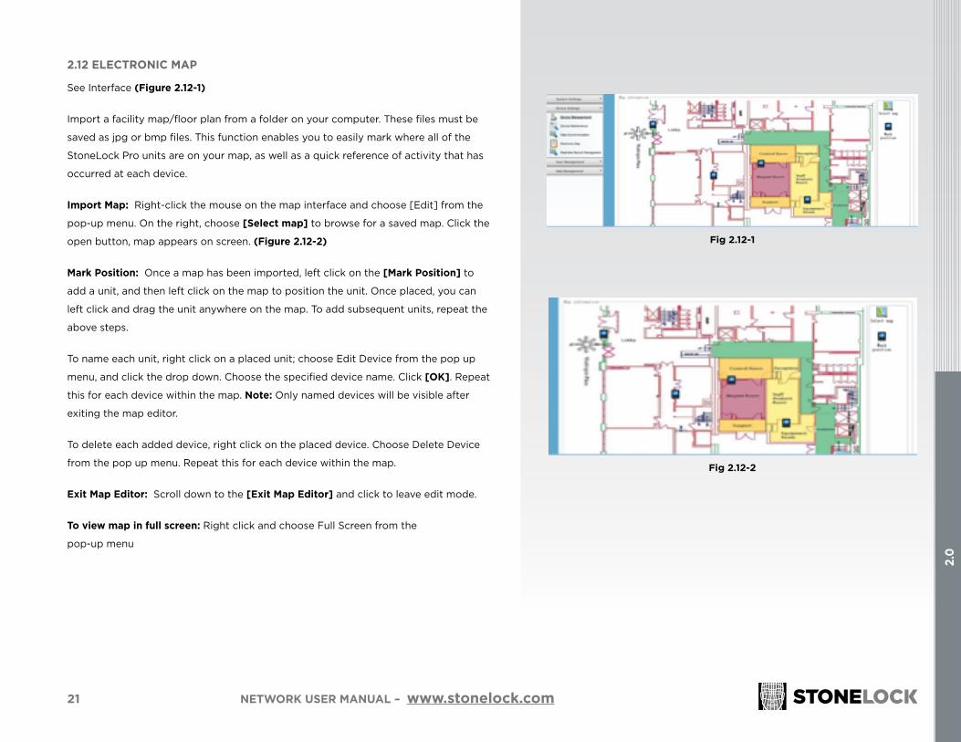
2.12 ELECTRONIC MAP
See Interface (Figure 2.12-1)
Import a facility map/floor plan from a folder on your computer. These files must be
saved as jpg or bmp files. This function enables you to easily mark where all of the
StoneLock Pro units are on your map, as well as a quick reference of activity that has
occurred at each device.
Import Map: Right-click the mouse on the map interface and choose [Edit] from the
pop-up menu. On the right, choose [Select map] to browse for a saved map. Click the
open button, map appears on screen. (Figure 2.12-2)
Mark Position: Once a map has been imported, left click on the [Mark Position] to
add a unit, and then left click on the map to position the unit. Once placed, you can
left click and drag the unit anywhere on the map. To add subsequent units, repeat the
above steps.
To name each unit, right click on a placed unit; choose Edit Device from the pop up
menu, and click the drop down. Choose the specified device name. Click [OK]. Repeat
this for each device within the map. Note: Only named devices will be visible after
exiting the map editor.
To delete each added device, right click on the placed device. Choose Delete Device
from the pop up menu. Repeat this for each device within the map.
Exit Map Editor: Scroll down to the [Exit Map Editor] and click to leave edit mode.
To view map in full screen: Right click and choose Full Screen from the
pop-up menu
Fig 2.12-1
Fig 2.12-2

22
2.0
NETWORK USER MANUAL – www.stonelock.com
2.13 REAL-TIME RECORDS MANAGEMENT
See Interface (Figure 2-30)
Real-time Records Display: the window of “Real-time record management” displays verification
details about the user immediately after they are successfully verified by a connected StoneLock Pro
unit. Information provided includes; name, ID, department, event, device accessed, time, and a real-
time photo of the event. This window contains the last 100 records.
Note: Real-Time records can only be displayed when you check “Display Real-time Record” from the “Device Settings - Device Management - Device Status” window. For detailed operations, see 2.3.1 Device Manager.
Click the [Filter Setting] button to pop up “Filter Settings” window (Figure 2-31). You can only filter
real-time records on any device checked.
Click [OK].
Fig 2.13-1
Fig 2.13-2

23
2.0
NETWORK USER MANUAL – www.stonelock.com
Click the [Subtitle Settings] button to open the dialog box shown in Figure 2.13-3. User can specify the
font and color of the window caption.
Click the [Mute] button to mute the system’s current event alarm.
Remote Assistance: The system does not display “Remote Assistance” window by default, unless when
StoneLock device sends a request to open the door remotely. Once the administrator confirms the
request, the window will be hidden.
2.14 USER MANAGEMENT
Click the [User Management] menu to pop up the menu bar as shown in Figure 2.14-1.
Fig 2.13-1
Fig 2.14-1

24
2.0
NETWORK USER MANUAL – www.stonelock.com
2.15 TIME GROUP MANAGEMENT
See Time Group Management Interface (Figure 2.15-1)
New: Click the [New] button to create a new time group. Set its name, start and end dates and
times. Choose time, day, month, year filters as desired. Click [Save] button.
Take time group 1 in Figure 2.15-1 for example, different detecting method bring different valid period
of permission as follows:
Note: All filters actions are driven from the chosen start date.
Check Year: The valid period is valid 2011 to end of 2012.
Check Month: The valid period is from start date in May to June in any year.
Check Day: The valid period is from 16th to 27th in any month and year.
Check Time: The valid period is 08:00:00-18:00:00 in any day.
Check Week: If Monday is checked, the valid period is Monday in any month and year.
Simultaneous check year and month: The valid period is from May, 2011 to June, 2012.
Simultaneous check year, month and day: The valid period is from May 16, 2011 to June 27, 2012.
Simultaneous check month and day: The valid period is from May 16, to June 27 in any year.
Simultaneous check year and day: The valid period is from 16th to 27th in every month from 2011 to
2012.
Fig 2.15-1
25
2.0
NETWORK USER MANUAL – www.stonelock.com
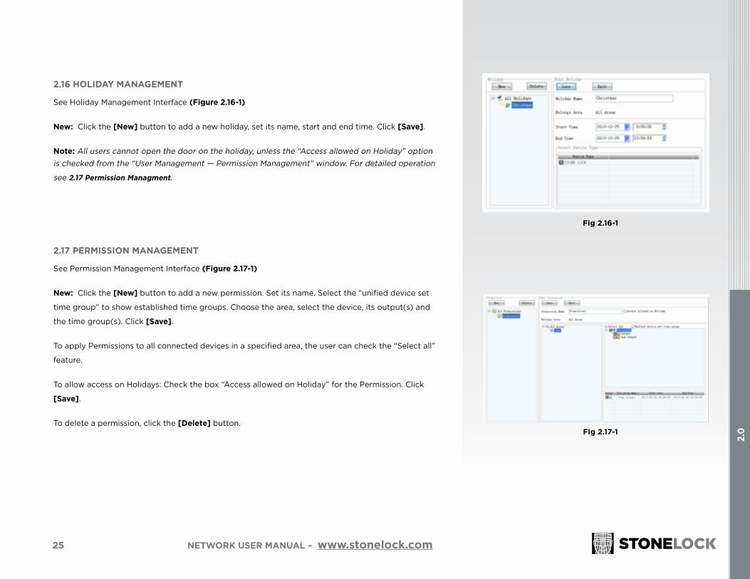
2.16 HOLIDAY MANAGEMENT
See Holiday Management Interface (Figure 2.16-1)
New: Click the [New] button to add a new holiday, set its name, start and end time. Click [Save].
Note: All users cannot open the door on the holiday, unless the “Access allowed on Holiday” option is checked from the “User Management — Permission Management” window. For detailed operation
see 2.17 Permission Managment.
2.17 PERMISSION MANAGEMENT
See Permission Management Interface (Figure 2.17-1)
New: Click the [New] button to add a new permission. Set its name. Select the “unified device set
time group” to show established time groups. Choose the area, select the device, its output(s) and
the time group(s). Click [Save].
To apply Permissions to all connected devices in a specified area, the user can check the “Select all”
feature.
To allow access on Holidays: Check the box “Access allowed on Holiday” for the Permission. Click
[Save].
To delete a permission, click the [Delete] button.
Fig 2.16-1
Fig 2.17-1
26
2.0
NETWORK USER MANUAL – www.stonelock.com
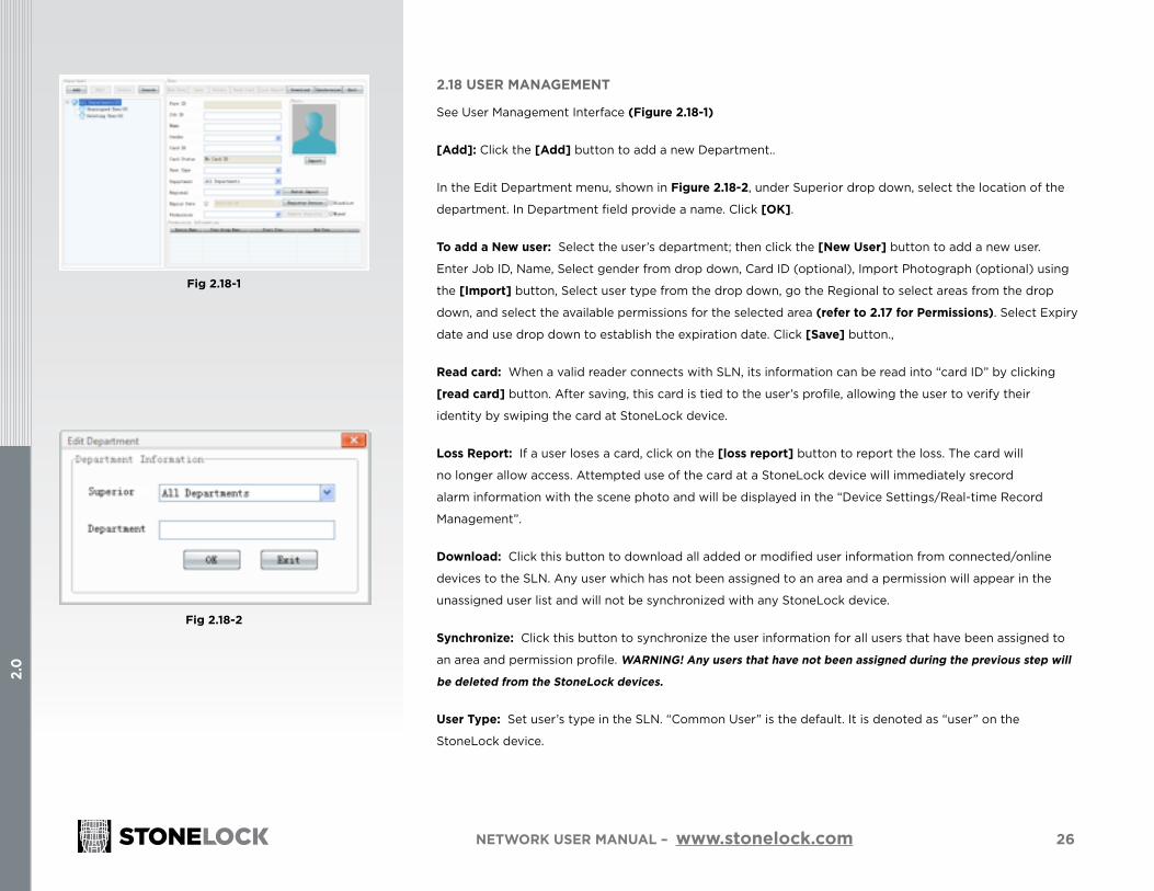
2.18 USER MANAGEMENT
See User Management Interface (Figure 2.18-1)
[Add]: Click the [Add] button to add a new Department..
In the Edit Department menu, shown in Figure 2.18-2, under Superior drop down, select the location of the
department. In Department field provide a name. Click [OK].
To add a New user: Select the user’s department; then click the [New User] button to add a new user.
Enter Job ID, Name, Select gender from drop down, Card ID (optional), Import Photograph (optional) using
the [Import] button, Select user type from the drop down, go the Regional to select areas from the drop
down, and select the available permissions for the selected area (refer to 2.17 for Permissions). Select Expiry
date and use drop down to establish the expiration date. Click [Save] button.,
Read card: When a valid reader connects with SLN, its information can be read into “card ID” by clicking
[read card] button. After saving, this card is tied to the user’s profile, allowing the user to verify their
identity by swiping the card at StoneLock device.
Loss Report: If a user loses a card, click on the [loss report] button to report the loss. The card will
no longer allow access. Attempted use of the card at a StoneLock device will immediately srecord
alarm information with the scene photo and will be displayed in the “Device Settings/Real-time Record
Management”.
Download: Click this button to download all added or modified user information from connected/online
devices to the SLN. Any user which has not been assigned to an area and a permission will appear in the
unassigned user list and will not be synchronized with any StoneLock device.
Synchronize: Click this button to synchronize the user information for all users that have been assigned to
an area and permission profile. WARNING! Any users that have not been assigned during the previous step will
be deleted from the StoneLock devices.
User Type: Set user’s type in the SLN. “Common User” is the default. It is denoted as “user” on the
StoneLock device.
Fig 2.18-1
Fig 2.18-2

27
2.0
NETWORK USER MANUAL – www.stonelock.com
Super Administrator: Users set as super administrator can operate all settings
on the StoneLock device. It is denoted as “S-Admin” on the StoneLock device.
Common Administrator: Users set as common administrator can perform new
user enrollment of a user and query records. It is denoted as “Admin” on the
StoneLock device.
Common User: Users Set as common user can only be verified at a StoneLock
device. It is noted as “User” on the StoneLock device.
Expiry Date: This function becomes active by checking the box and setting
a date with the Drop down. Users are allowed to be verified at a StoneLock
device until the date set on the expiry date field. If access is attempted after the
expiration date, an alarm event with a scene photo will be sent to the SLN and
displayed on the “Device settings/Real-time record management“ window.
Blacklist: Check this option to put a user into the blacklist. The user will never
be verified at a StoneLock device, if the blacklisted user attempts access, alarm
information with a scene photo will be sent to the SLN and displayed on the
window of “Device settings/Real-time record management“.
Mixed Mode: When this box is checked, this function enables a user to gain
access at a StoneLock device using either a [Card + Face] or Face only.
Note: There is a limit of up to 200 users that can be set to mixed mode in the SLN and the device must also be set to Mixed Mode (Refer to 2.3.1 to learn more).
Registry Device: Click this button to open a dialogue box and choose the
device you wish to use for Remote Enrollment. Select the device and click [OK].
Remote Registry: Click this button to remotely register a user using the
Registry device selected. You must select a Registry device as mentioned above
to remotely enroll a user.
Unassigned users: Any new user that is enrolled or downloaded from a device
will be defaulted as an unassigned user. To assign an unassigned user, select
the unassigned “new user” on the left, enter Job/Employee ID, Name, Select
gender from drop down, Card ID (optional), Import Photograph (optional) using
the [Import] button, Select user type from the drop down, go the Regional to
select areas from the drop down, and select the available permissions for the
selected area (refer to 2.4.3 for permissions). Select Expiry date and use drop
down to establish the expiration date. Click [Save] button.
Deleting user: Users that are on a device and have been pulled in via
the [Synchronize] button will be placed in this category since they are
“unassigned”.
28
2.0
NETWORK USER MANUAL – www.stonelock.com
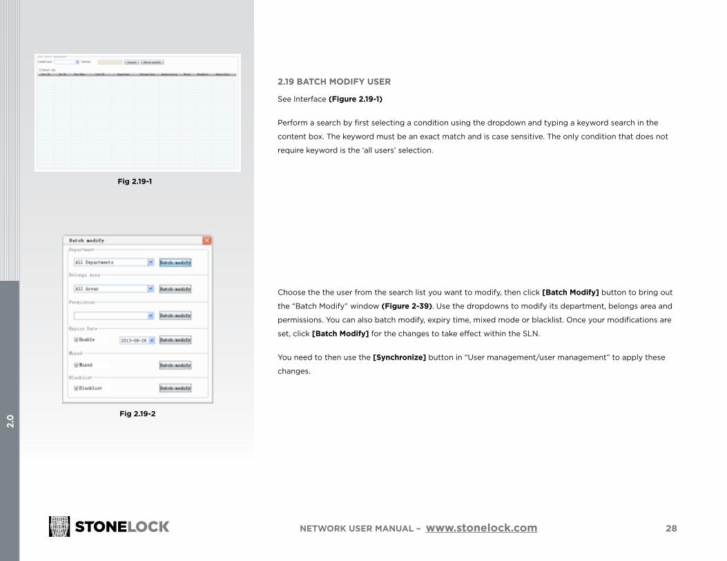
2.19 BATCH MODIFY USER
See Interface (Figure 2.19-1)
Perform a search by first selecting a condition using the dropdown and typing a keyword search in the
content box. The keyword must be an exact match and is case sensitive. The only condition that does not
require keyword is the ‘all users’ selection.
Choose the the user from the search list you want to modify, then click [Batch Modify] button to bring out
the “Batch Modify” window (Figure 2-39). Use the dropdowns to modify its department, belongs area and
permissions. You can also batch modify, expiry time, mixed mode or blacklist. Once your modifications are
set, click [Batch Modify] for the changes to take effect within the SLN.
You need to then use the [Synchronize] button in “User management/user management” to apply these
changes.
Fig 2.19-1
Fig 2.19-2
29
2.0
NETWORK USER MANUAL – www.stonelock.com
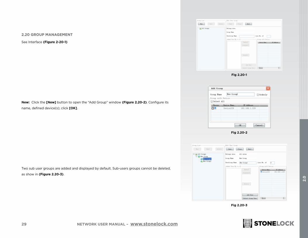
2.20 GROUP MANAGEMENT
See Interface (Figure 2-20-1)
New: Click the [New] button to open the “Add Group” window (Figure 2.20-2). Configure its
name, defined device(s); click [OK].
Two sub user groups are added and displayed by default. Sub-users groups cannot be deleted,
as show in (Figure 2.20-3).
Fig 2.20-1
Fig 2.20-2
Fig 2.20-3

30
2.0
NETWORK USER MANUAL – www.stonelock.com
Add User: Select a sub user group, click the [Add User] button to open the “Select User” window
(Figure 2.20-4).
Perform a search by first selecting a condition using the dropdown and typing a keyword search
in the content box. The keyword must be an exact match and is case sensitive. The only condition
that does not require keyword is the ‘all users’ selection.
Choose up to SIX users by checking the box next to the user from the search list, then click [OK].
To move a user up or down in a list, click on the user in the list and then click the [Upward] and
[Downward] buttons respectively.
To delete a user in a list, click on the user in the list and then click the [Delete] button.
Click [Save] to save all modifications to the group.
Less No. of: Set the at least turnout in sub user group. Take the number in Figure 2.20-5 for
example; any two of users in the sub use group that appear will do.
Orderly: If you check this option, users in sub user group must be verified orderly, otherwise
combine verification is invalid. You can reorder it by clicking [up], [down] buttons.
Note: Two sub user groups by default can be set in a combination, and each contain a maximum
of six users. When checking “recognizing orderly”, the first group will be verified before the second
one.
Fig 2.20-4
Fig 2.20-5
Fig 2.20-6

31
2.0
NETWORK USER MANUAL – www.stonelock.com
2.21 DATA MANAGEMENT
Click [Data Management] to open the menu bar (Figure 2.21-1).
2.22 VERIFICATION RECORDS MANAGEMENT
See Interface (Figure 2.22-1)
Click the [Search] button, the system by default will search the current day’s verification records of all
devices and users. The search can be expanded by setting the start and end dates/times of the search.
You can filter the search by choosing the device, the department, name, id number, card number, type of
verification and the event associated with that verification/denial..
Note: All records are downloaded automatically or can be manually downloaded by an administrator from a StoneLock device to the SLN. Refer to 2.11-1 for Data Synchronization.
2.23 ALARM RECORDS MANAGEMENT
See Interface (Figure 2.23-1)
Click the [Search] button, the system by default will search the current day’s alarm records of all
devices. The search can be expanded by setting the start and end dates/times of the search.
You can filter the search by choosing the device, the alarm type, id number and card number.
Note: All records are downloaded automatically or can be manually downloaded by an administrator from a StoneLock device to the SLN. (Refer to 2.11-1 for Data Synchronization).
Fig 2.21-1
Fig 2.22-1
Fig 2.23-1

Please contact StoneLock with any comments or questions regarding the material in this User Guide.
Visit our website at:
www.stonelock.com

StoneLock, Inc.1-800-970-6168 • [email protected] • www.stonelock.com Rev 2.01.2017