stp.1115 user’s guide - century systems, inc. determination of the suitability of any information...
TRANSCRIPT

STp.1115User’s Guide


STp.1115
User’s Guide
Source Technologies, LLC2910 Whitehall Park Drive
Charlotte, NC 28273Phone: 1.800.922.8501
Fax: 704.969.7595
www.sourcetech.com


STp.1115 User’s Guide
Copyright
Copyright ©2012 by Source Technologies, LLC. All rights reserved.
No part of this document may be reproduced or utilized in any form or by any meanselectronic or mechanical, including photocopying, recording or by any informationstorage and retrieval system, without permission in writing from Source Technologies.
Published in the United States of America by:
Source Technologies, LLC
2910 Whitehall Park Drive
Charlotte, NC 28273
Author: Source Technologies, LLC
NoticeTo the best of our knowledge, the information in this publication is accurate: however,Source Technologies, LLC does not assume any responsibility or liability for the accuracyor completeness of, or consequences arising from, such information. This document isintended for informational purposes only. Mention of trade names or commercialproducts does not constitute endorsement or recommendation for use by SourceTechnologies, LLC. Final determination of the suitability of any information or product foruse contemplated by any user, and the manner of that use is the sole responsibility of theuser. We recommend that anyone intending to rely on any recommendation of materialsor procedures mentioned in this publication should satisfy himself as to such suitability,and that he can meet all applicable safety and health standards.
All trademarks and registered trademarks appearing in this document are the property oftheir respective owners.
The content of this manual is provided exclusively for Source Technologies’ Beta TestProgram and is not intended to be used for any production-released product.
Document Number: TP1001UG
Revision: A


Agency ComplianceThis product complies to the following:
CFR 47 Part 15, Class A Digital Device
This device complies with Part 15 of the FCC Rules. Operation is subject to the following two conditions: 1) This device may not cause harmful interference, and 2) this device must accept any interference received, including interference that may cause undesired operation.
This Class A digital apparatus complies with Industry Canada ICS-003 class A requirements.
UL 60950-1 Safety of Information Technology Equipment Including Electrical Business Equipment
CAN/CSA-C22.2 No.60950-1 Safety of Information Technology Equipment Including Electrical Business Equipment
European Council Directive 2004/108/EC “EMC Directive”
EN55022, Emissions, Class A
EN55024, Immunity
EN61000-3-2, Harmonics
EN61000-3-3, Voltage Fluctuations and Flicker
European Council Directive 206/95/EC “Low Voltage Directive”
EN60950-1
IEC 60950-1 (CB Scheme)
IEC 60825-1 Safety of Laser Products (applies to barcode reader option)
EN 300 328 V1.7.1 (2006-10) - Electromagnetic Compatibility and Radio Spectrum Matters (applies to 802.11b/g wireless module option
EN45014 General Criteria for Suppliers Declaration of Conformity
Directive 93/68/EEC CE Marking

GOST-R (Russia)
WEEE Information for Source Technologies Customers and Recyclers (Europe)
Under the European Union’s Waste Electrical and Electronic Equipment (WEEE) Directive and implementing regulations, when customers buy new thermal printer equipment from Source Technologies they are entitled to send the new equipment back for recycling when this ultimately becomes waste.
Instructions to both EU customers and recyclers/treatment facilities wishing to obtain disassembly information are provided by following the link below:
http://www.sourcetech.com/support/recycling-disposal/weee
Directive 2002/95/EC Restrictions on the Use of Certain Hazardous Substances in Electronics and Electric Equipment (RoHS)
Directive 2002/96/EC Waste Electrical and Electronics Equipment (WEEE)
Directive 94/62/EC Packaging and Packaging Waste
RoHS Compliant
A R12
STp.1115 User’s Guide
Table of Contents
Table of Contents
1. SafetyWarnings and Cautions ........................................................................................ 1General Safety Information ................................................................................... 1
2. OverviewAbout the Printer ................................................................................................... 3Standard Features ................................................................................................ 6Options ................................................................................................................. 7Unpacking the Printer ........................................................................................... 8Checking the Contents ......................................................................................... 8Specifications ....................................................................................................... 8
3. Connections and SetupConnections ........................................................................................................ 11Media Loading .................................................................................................... 11Media Hanger - Self-Centering ........................................................................... 12Media Hanger - Cantilever .................................................................................. 19Installing Ribbon ................................................................................................. 27Configuring Media and Ribbon Settings ............................................................. 32Optional Rewinder .............................................................................................. 35Top-of-Form Sensor ........................................................................................... 36Removing Ribbon Wrinkle .................................................................................. 41Manual Head Pressure Adjustment .................................................................... 43Installing Cutter and Tray ................................................................................... 45Print Driver Installation ....................................................................................... 48Printer Properties ................................................................................................ 74Printing Preferences ........................................................................................... 76
4. Menu SystemMenu Overview ................................................................................................... 81Layout of the Display .......................................................................................... 81Home Screen ...................................................................................................... 82Information Button ............................................................................................. 83Feed Button ........................................................................................................ 87
Table of Contents
STp.1115User’s Guide
Menu .................................................................................................................. 87
5. Cleaning and MaintenanceOverview ........................................................................................................... 117Intervals ............................................................................................................ 117Supplies ............................................................................................................ 117Cleaning the Automatic Loading Sensor .......................................................... 118Cleaning the Top-of-Form Sensor .................................................................... 118Cleaning the Label Low Sensor ........................................................................ 118Cleaning the Printhead ..................................................................................... 118Cleaning the Cutter ........................................................................................... 119
6. TroubleshootingErrors ................................................................................................................ 121Warnings .......................................................................................................... 122Troubleshooting ................................................................................................ 122Troubleshooting Print Quality ........................................................................... 125
7. Terms and DefinitionsProcessing State .............................................................................................. 127Printer State ...................................................................................................... 127Media Setup ..................................................................................................... 127Basic ................................................................................................................. 127Advanced .......................................................................................................... 128Tools ................................................................................................................. 132Test ................................................................................................................... 133
8. Appendix ASymbol Sets ..................................................................................................... 135Fonts ................................................................................................................. 136Barcodes .......................................................................................................... 138
1 STp.1115 User’s Guide
1 Safety
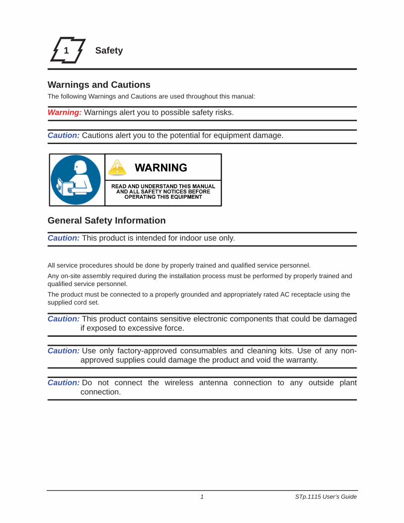
Warnings and CautionsThe following Warnings and Cautions are used throughout this manual:
Warning: Warnings alert you to possible safety risks.
Caution: Cautions alert you to the potential for equipment damage.
General Safety Information
Caution: This product is intended for indoor use only.
All service procedures should be done by properly trained and qualified service personnel.Any on-site assembly required during the installation process must be performed by properly trained and qualified service personnel.The product must be connected to a properly grounded and appropriately rated AC receptacle using the supplied cord set.
Caution: This product contains sensitive electronic components that could be damagedif exposed to excessive force.
Caution: Use only factory-approved consumables and cleaning kits. Use of any non-approved supplies could damage the product and void the warranty.
Caution: Do not connect the wireless antenna connection to any outside plantconnection.

1 | Safety
STp.1115 User’s Guide 2
This product must be connected to a properly grounded and appropriately rated AC receptacle.
Figure: 1 - 1 Caution - Hot
The printhead heats during printing. Do not touch.
3 STp.1115 User’s Guide
2 Overview
About the Printer
Product Tour
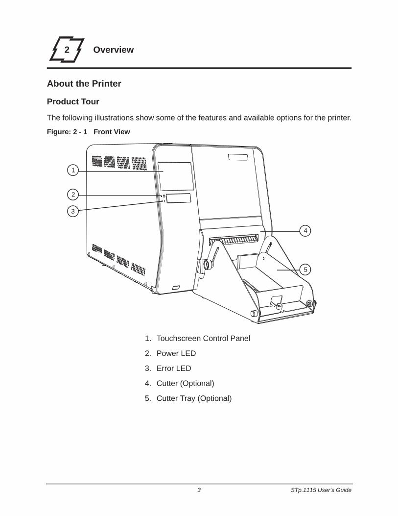
The following illustrations show some of the features and available options for the printer.
Figure: 2 - 1 Front View
1. Touchscreen Control Panel
2. Power LED
3. Error LED
4. Cutter (Optional)
5. Cutter Tray (Optional)
1
2
3
4
5
2 | Overview
STp.1115 User’s Guide 4
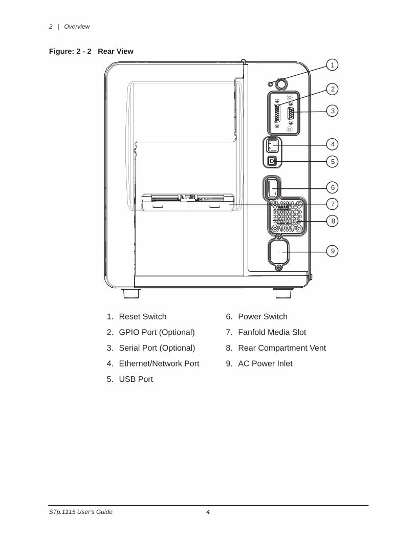
Figure: 2 - 2 Rear View
1
2
3
4
5
6
7
8
9
1. Reset Switch
2. GPIO Port (Optional)
3. Serial Port (Optional)
4. Ethernet/Network Port
5. USB Port
6. Power Switch
7. Fanfold Media Slot
8. Rear Compartment Vent
9. AC Power Inlet
Overview | 2
5 STp.1115 User’s Guide
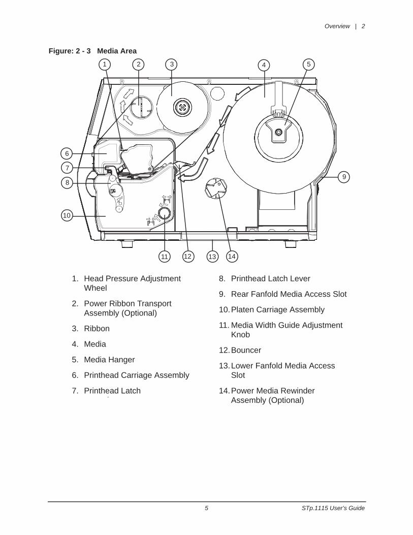
Figure: 2 - 3 Media Area
.
1. Head Pressure Adjustment Wheel
2. Power Ribbon Transport Assembly (Optional)
3. Ribbon
4. Media
5. Media Hanger
6. Printhead Carriage Assembly
7. Printhead Latch
8. Printhead Latch Lever
9. Rear Fanfold Media Access Slot
10.Platen Carriage Assembly
11. Media Width Guide Adjustment Knob
12.Bouncer
13.Lower Fanfold Media Access Slot
14.Power Media Rewinder Assembly (Optional)
1 2 3 4 5
6
7
89
10
11 12 13 14
2 | Overview
STp.1115 User’s Guide 6
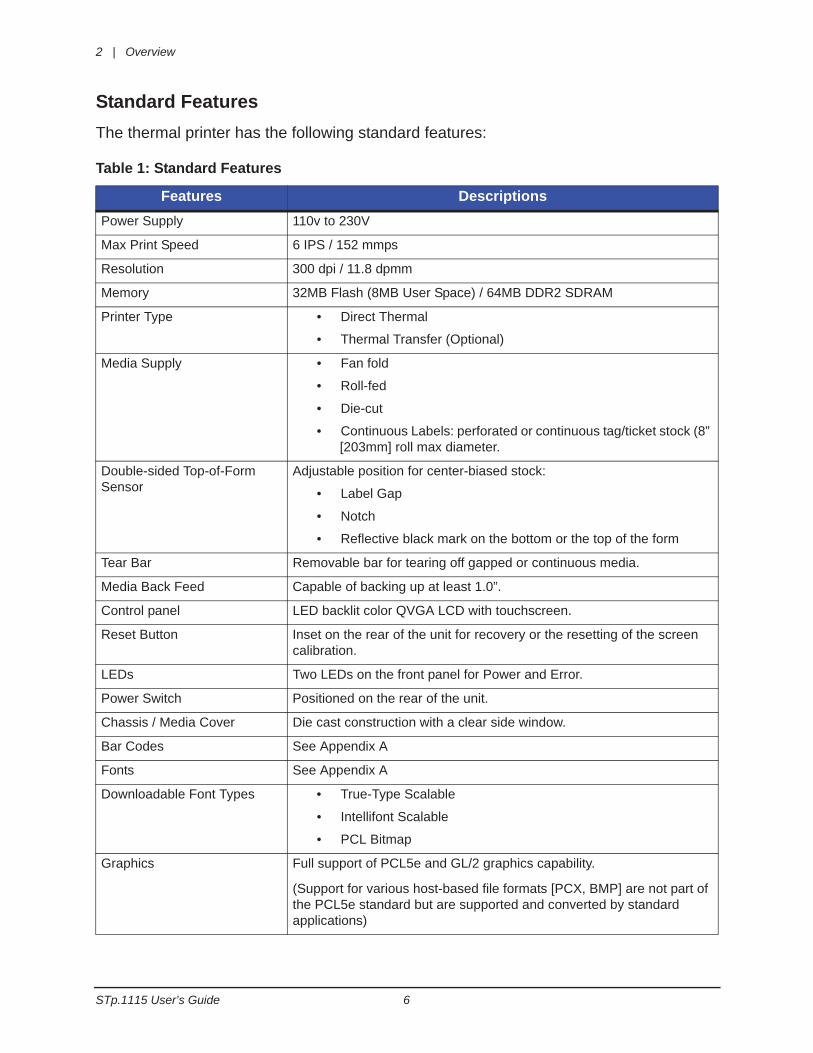
Standard FeaturesThe thermal printer has the following standard features:
Table 1: Standard Features
Features DescriptionsPower Supply 110v to 230V
Max Print Speed 6 IPS / 152 mmps
Resolution 300 dpi / 11.8 dpmm
Memory 32MB Flash (8MB User Space) / 64MB DDR2 SDRAM
Printer Type • Direct Thermal
• Thermal Transfer (Optional)
Media Supply • Fan fold
• Roll-fed
• Die-cut
• Continuous Labels: perforated or continuous tag/ticket stock (8” [203mm] roll max diameter.
Double-sided Top-of-Form Sensor
Adjustable position for center-biased stock:
• Label Gap
• Notch
• Reflective black mark on the bottom or the top of the form
Tear Bar Removable bar for tearing off gapped or continuous media.
Media Back Feed Capable of backing up at least 1.0”.
Control panel LED backlit color QVGA LCD with touchscreen.
Reset Button Inset on the rear of the unit for recovery or the resetting of the screen calibration.
LEDs Two LEDs on the front panel for Power and Error.
Power Switch Positioned on the rear of the unit.
Chassis / Media Cover Die cast construction with a clear side window.
Bar Codes See Appendix A
Fonts See Appendix A
Downloadable Font Types • True-Type Scalable
• Intellifont Scalable
• PCL Bitmap
Graphics Full support of PCL5e and GL/2 graphics capability.
(Support for various host-based file formats [PCX, BMP] are not part of the PCL5e standard but are supported and converted by standard applications)
Overview | 2
7 STp.1115 User’s Guide
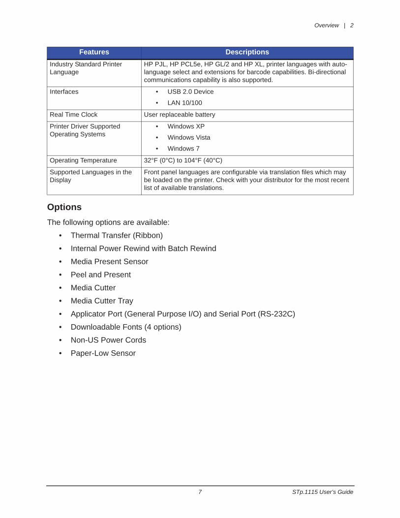
OptionsThe following options are available:
• Thermal Transfer (Ribbon)
• Internal Power Rewind with Batch Rewind
• Media Present Sensor
• Peel and Present
• Media Cutter
• Media Cutter Tray
• Applicator Port (General Purpose I/O) and Serial Port (RS-232C)
• Downloadable Fonts (4 options)
• Non-US Power Cords
• Paper-Low Sensor
Industry Standard Printer Language
HP PJL, HP PCL5e, HP GL/2 and HP XL, printer languages with auto-language select and extensions for barcode capabilities. Bi-directional communications capability is also supported.
Interfaces • USB 2.0 Device
• LAN 10/100
Real Time Clock User replaceable battery
Printer Driver Supported Operating Systems
• Windows XP
• Windows Vista
• Windows 7
Operating Temperature 32°F (0°C) to 104°F (40°C)
Supported Languages in the Display
Front panel languages are configurable via translation files which may be loaded on the printer. Check with your distributor for the most recent list of available translations.
Features Descriptions
2 | Overview
STp.1115 User’s Guide 8
Unpacking the PrinterUpon receiving the printer, verify the box is undamaged. Carefully unpack the printer from its packaging and visually check for any physical damage that may have occurred during shipment.
Checking the ContentsThe contents may vary depending on your configuration. It is recommended that all packaging materials be saved if the printer is to be shipped again. If the packaging material is discarded, new packaging material may be available from your reseller.
• Printer
• Power Cord
• Driver CD
• Product documentation not included on the CD
• Accessories/Options
Additional items that may be required include the following:
• All Applicable Communication Cables
• Media
• Ribbon
Specifications
Print Characteristics
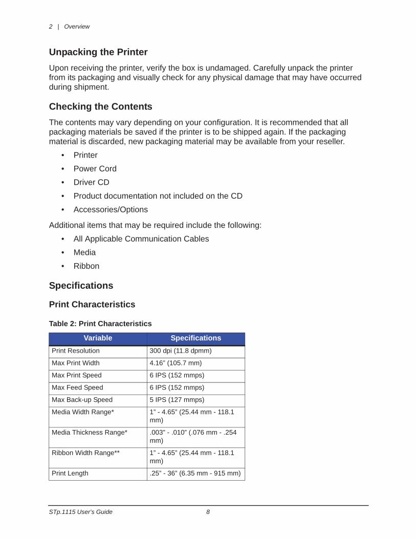
Table 2: Print Characteristics
Variable SpecificationsPrint Resolution 300 dpi (11.8 dpmm)
Max Print Width 4.16” (105.7 mm)
Max Print Speed 6 IPS (152 mmps)
Max Feed Speed 6 IPS (152 mmps)
Max Back-up Speed 5 IPS (127 mmps)
Media Width Range* 1” - 4.65” (25.44 mm - 118.1 mm)
Media Thickness Range* .003” - .010” (.076 mm - .254 mm)
Ribbon Width Range** 1” - 4.65” (25.44 mm - 118.1 mm)
Print Length .25” - 36” (6.35 mm - 915 mm)
Overview | 2
9 STp.1115 User’s Guide
*Media wound out.
**Coated side in or out.
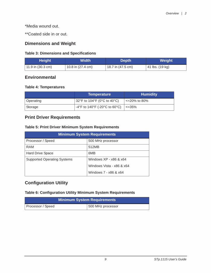
Dimensions and Weight
Table 3: Dimensions and Specifications
Environmental
Table 4: Temperatures
Print Driver Requirements
Table 5: Print Driver Minimum System Requirements
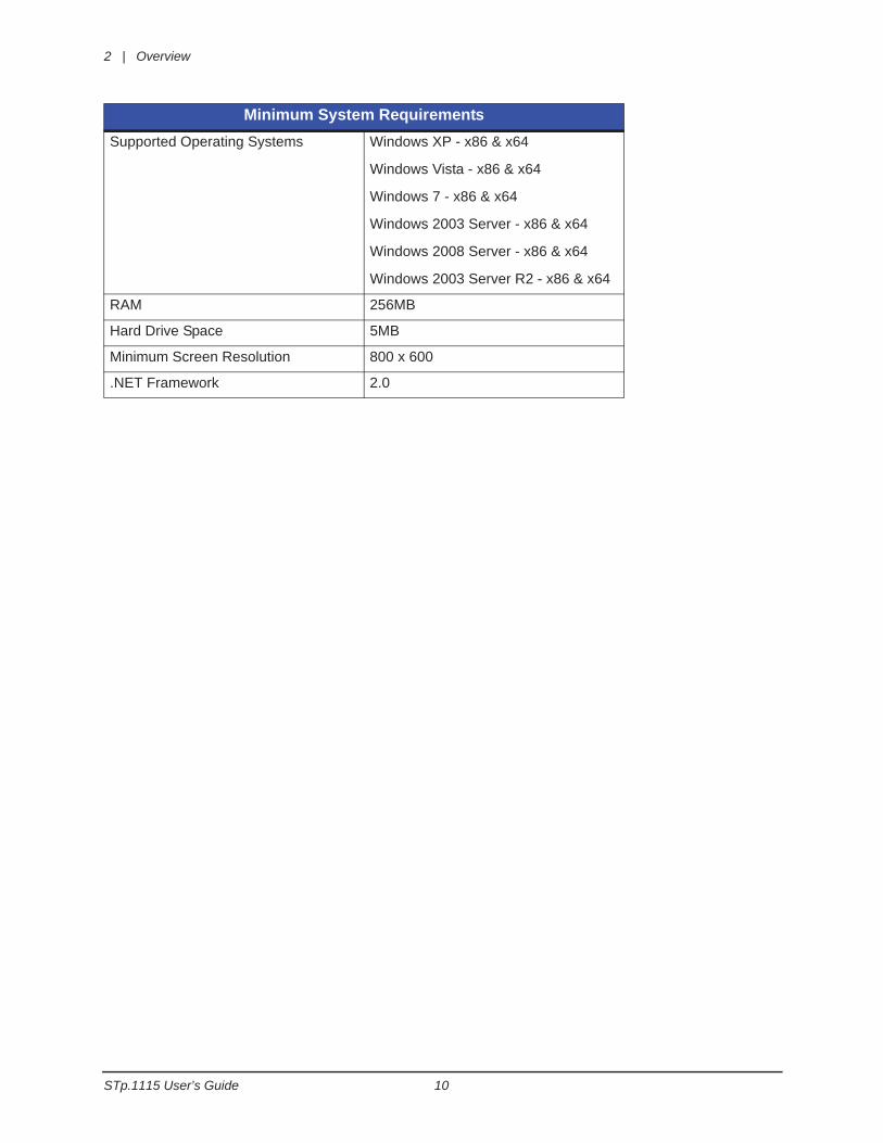
Configuration Utility
Table 6: Configuration Utility Minimum System Requirements
Height Width Depth Weight11.9 in (30.3 cm) 10.8 in (27.4 cm) 18.7 in (47.5 cm) 41 lbs. (19 kg)
Temperature HumidityOperating 32°F to 104°F (0°C to 40°C) <=20% to 80%
Storage -4°F to 140°F (-20°C to 60°C) <=35%
Minimum System RequirementsProcessor / Speed 500 MHz processor
RAM 512MB
Hard Drive Space 6MB
Supported Operating Systems Windows XP - x86 & x64
Windows Vista - x86 & x64
Windows 7 - x86 & x64
Minimum System RequirementsProcessor / Speed 500 MHz processor
2 | Overview
STp.1115 User’s Guide 10
Supported Operating Systems Windows XP - x86 & x64
Windows Vista - x86 & x64
Windows 7 - x86 & x64
Windows 2003 Server - x86 & x64
Windows 2008 Server - x86 & x64
Windows 2003 Server R2 - x86 & x64
RAM 256MB
Hard Drive Space 5MB
Minimum Screen Resolution 800 x 600
.NET Framework 2.0
Minimum System Requirements
11 STp.1115 User’s Guide
3 Connections and Setup
Connections
Power
To connect the printer to a viable power source, please follow the steps below.
Caution: Ensure the printer power switch is off before connecting the AC power anddata/network connectivity cables to the printer.
Caution: Adhere to all environmental requirements when installing and using the printer.Use of the product in an unsuitable environment may affect print quality and thedurability of the printer and may void the manufacturer’s warranty.
1. Place the printer on a suitable level surface capable of securely supporting 50lbs.
2. Connect the AC power cord to the AC power inlet on the back of the printer.
3. Connect the AC power cord to AC utility power.
Data
Printer data connectivity can be accomplished by the following standard or optional interfaces:
• USB
• Ethernet/Network
• Serial (Optional)
• GPIO (Optional)
Connect the appropriate interface cables for your network configuration.
Media LoadingThe printer is designed to print on media that is center-aligned on the media hanger. There are two different media mounts available.
The standard self-centering media hanger synchronizes the adjustment to facilitate the centering of the media. The optional cantilever* mount requires the manual center-alignment of the media. (*The cantilever-type media hanger is not an available option for some Performance Series printers. Please check with your sales representative for availability.)
Please consult your reseller to obtain the appropriate media.
Note: The printer should be connected to AC power and running during media loading.
3 | Connections and Setup
STp.1115 User’s Guide 12
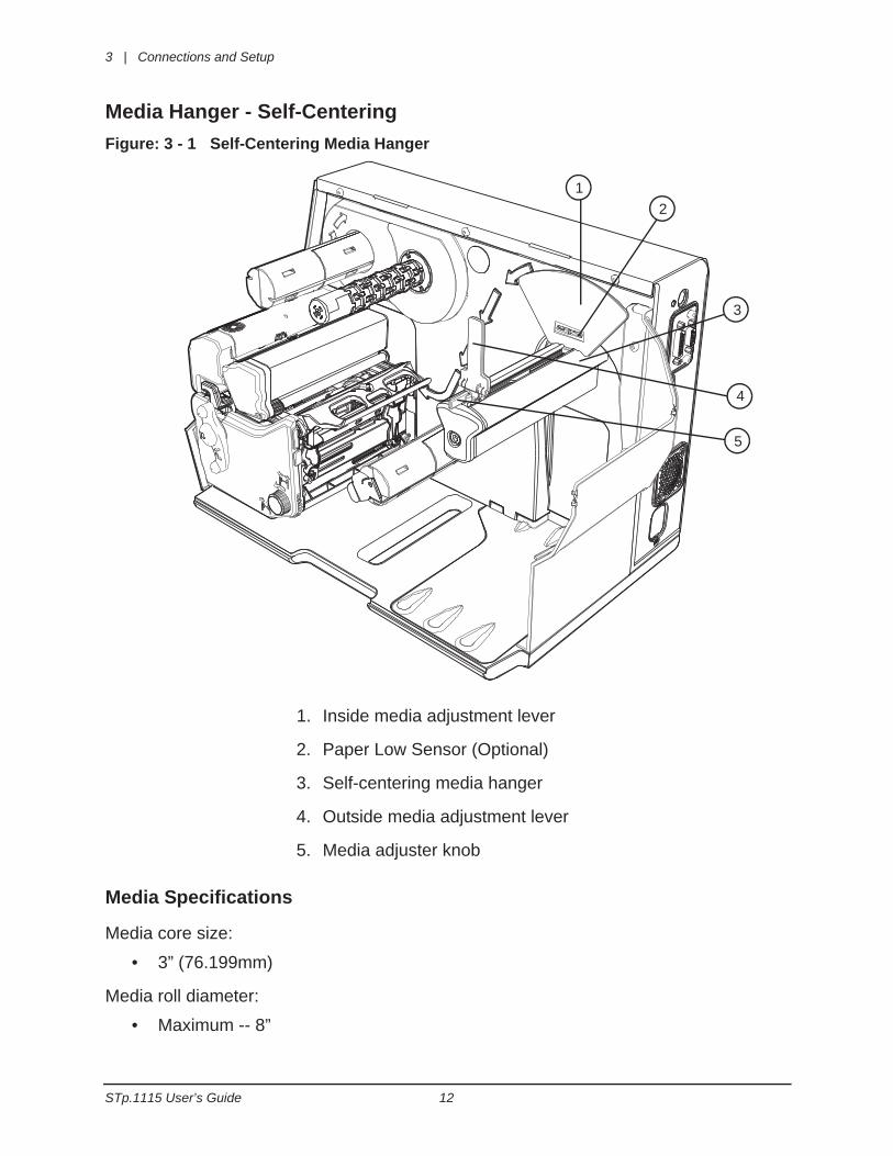
Media Hanger - Self-CenteringFigure: 3 - 1 Self-Centering Media Hanger
Media Specifications
Media core size:
• 3” (76.199mm)
Media roll diameter:
• Maximum -- 8”
1. Inside media adjustment lever
2. Paper Low Sensor (Optional)
3. Self-centering media hanger
4. Outside media adjustment lever
5. Media adjuster knob
12
3
4
5
Connections and Setup | 3
13 STp.1115 User’s Guide
Media Roll Width:
• Maximum -- 4.65”
Media thickness:
• .003” to .01”
Media dimensions:
• Minimum specifications - .5” H x 1” W
Note: Ensure there is no tape or adhesive residue on the media roll.
Installing Media for the First Time
1. Open the media cover.
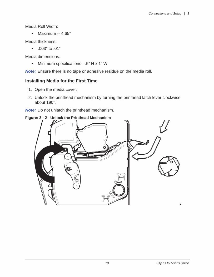
2. Unlock the printhead mechanism by turning the printhead latch lever clockwise about 190°.
Note: Do not unlatch the printhead mechanism.
Figure: 3 - 2 Unlock the Printhead Mechanism
3 | Connections and Setup
STp.1115 User’s Guide 14
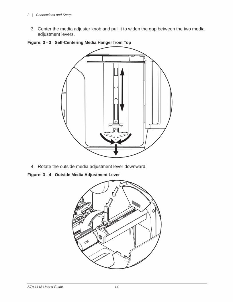
3. Center the media adjuster knob and pull it to widen the gap between the two media adjustment levers.
Figure: 3 - 3 Self-Centering Media Hanger from Top
4. Rotate the outside media adjustment lever downward.
Figure: 3 - 4 Outside Media Adjustment Lever
Connections and Setup | 3
15 STp.1115 User’s Guide
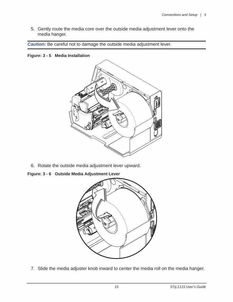
5. Gently route the media core over the outside media adjustment lever onto the media hanger.
Caution: Be careful not to damage the outside media adjustment lever.
Figure: 3 - 5 Media Installation
6. Rotate the outside media adjustment lever upward.
Figure: 3 - 6 Outside Media Adjustment Lever
7. Slide the media adjuster knob inward to center the media roll on the media hanger.
3 | Connections and Setup
STp.1115 User’s Guide 16
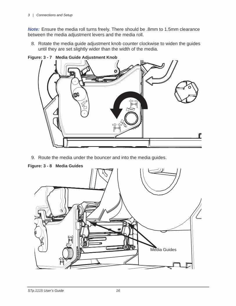
Note: Ensure the media roll turns freely. There should be .8mm to 1.5mm clearance between the media adjustment levers and the media roll.
8. Rotate the media guide adjustment knob counter clockwise to widen the guides until they are set slightly wider than the width of the media.
Figure: 3 - 7 Media Guide Adjustment Knob
9. Route the media under the bouncer and into the media guides.
Figure: 3 - 8 Media Guides
Media Guides
Connections and Setup | 3
17 STp.1115 User’s Guide
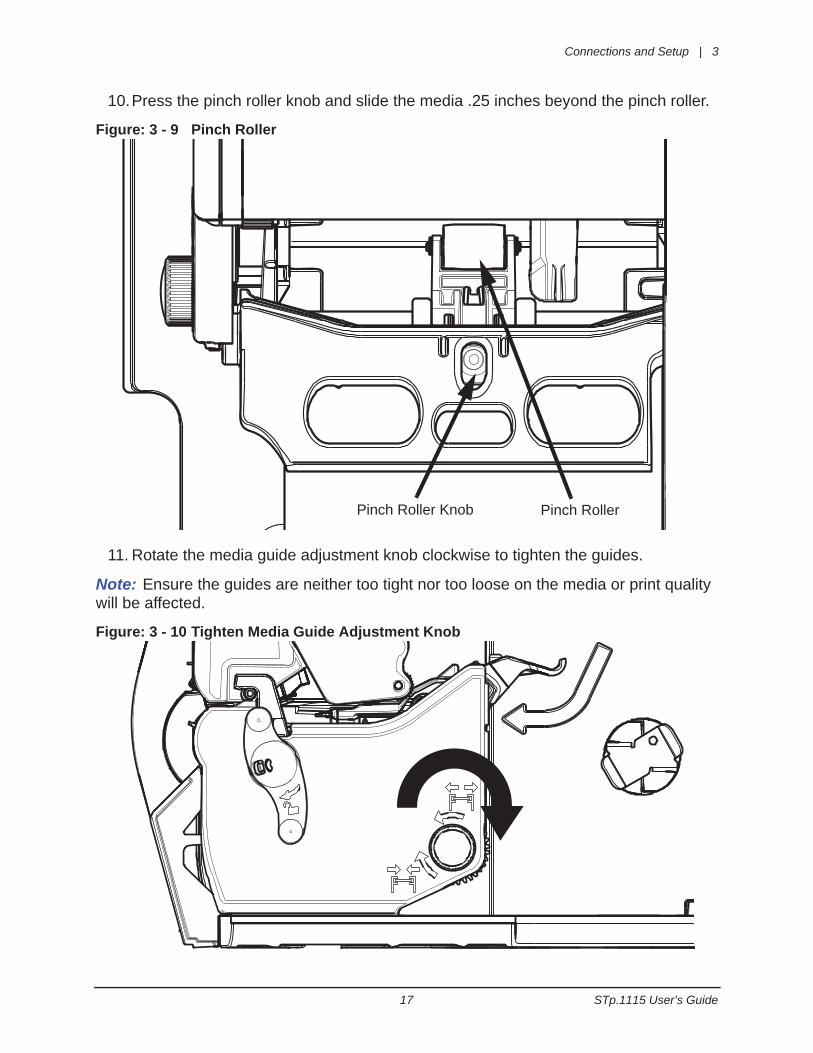
10.Press the pinch roller knob and slide the media .25 inches beyond the pinch roller.
Figure: 3 - 9 Pinch Roller
11. Rotate the media guide adjustment knob clockwise to tighten the guides.
Note: Ensure the guides are neither too tight nor too loose on the media or print quality will be affected.
Figure: 3 - 10 Tighten Media Guide Adjustment Knob
Pinch Roller Knob Pinch Roller
3 | Connections and Setup
STp.1115 User’s Guide 18
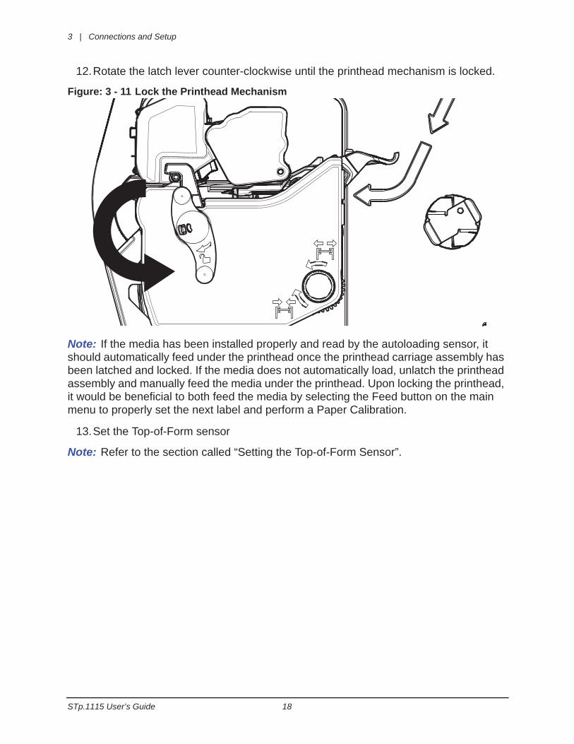
12.Rotate the latch lever counter-clockwise until the printhead mechanism is locked.
Figure: 3 - 11 Lock the Printhead Mechanism
Note: If the media has been installed properly and read by the autoloading sensor, it should automatically feed under the printhead once the printhead carriage assembly has been latched and locked. If the media does not automatically load, unlatch the printhead assembly and manually feed the media under the printhead. Upon locking the printhead, it would be beneficial to both feed the media by selecting the Feed button on the main menu to properly set the next label and perform a Paper Calibration.
13.Set the Top-of-Form sensor
Note: Refer to the section called “Setting the Top-of-Form Sensor”.
Connections and Setup | 3
19 STp.1115 User’s Guide
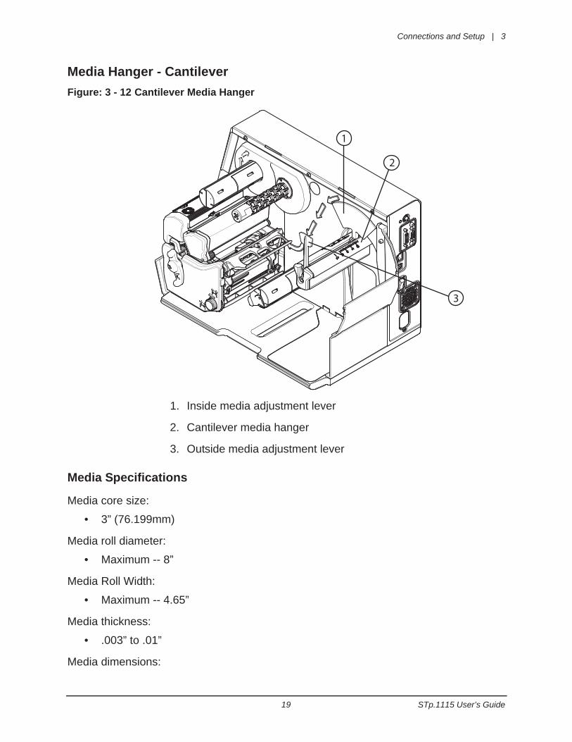
Media Hanger - CantileverFigure: 3 - 12 Cantilever Media Hanger
Media Specifications
Media core size:
• 3” (76.199mm)
Media roll diameter:
• Maximum -- 8”
Media Roll Width:
• Maximum -- 4.65”
Media thickness:
• .003” to .01”
Media dimensions:
1
2
3
1. Inside media adjustment lever
2. Cantilever media hanger
3. Outside media adjustment lever
3 | Connections and Setup
STp.1115 User’s Guide 20
• Minimum specifications - .5” H x 1” W
Note: Ensure there is no tape or adhesive residue on the media roll.
Installing Media for the First Time
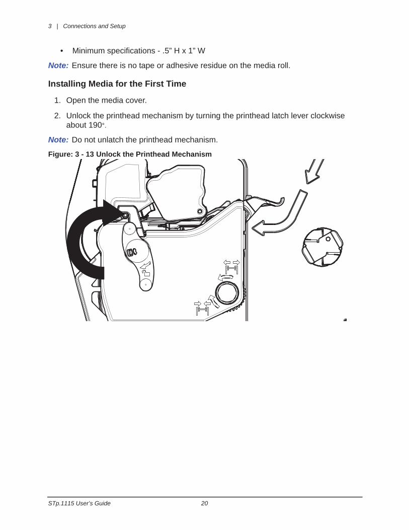
1. Open the media cover.
2. Unlock the printhead mechanism by turning the printhead latch lever clockwise about 190°.
Note: Do not unlatch the printhead mechanism.
Figure: 3 - 13 Unlock the Printhead Mechanism
Connections and Setup | 3
21 STp.1115 User’s Guide
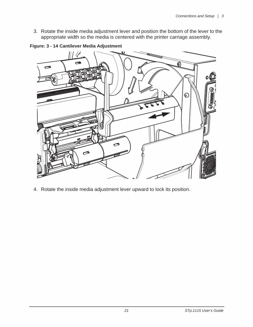
3. Rotate the inside media adjustment lever and position the bottom of the lever to the appropriate width so the media is centered with the printer carriage assembly.
Figure: 3 - 14 Cantilever Media Adjustment
4. Rotate the inside media adjustment lever upward to lock its position.
3 | Connections and Setup
STp.1115 User’s Guide 22
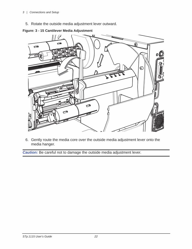
5. Rotate the outside media adjustment lever outward.
Figure: 3 - 15 Cantilever Media Adjustment
6. Gently route the media core over the outside media adjustment lever onto the media hanger.
Caution: Be careful not to damage the outside media adjustment lever.
Connections and Setup | 3
23 STp.1115 User’s Guide
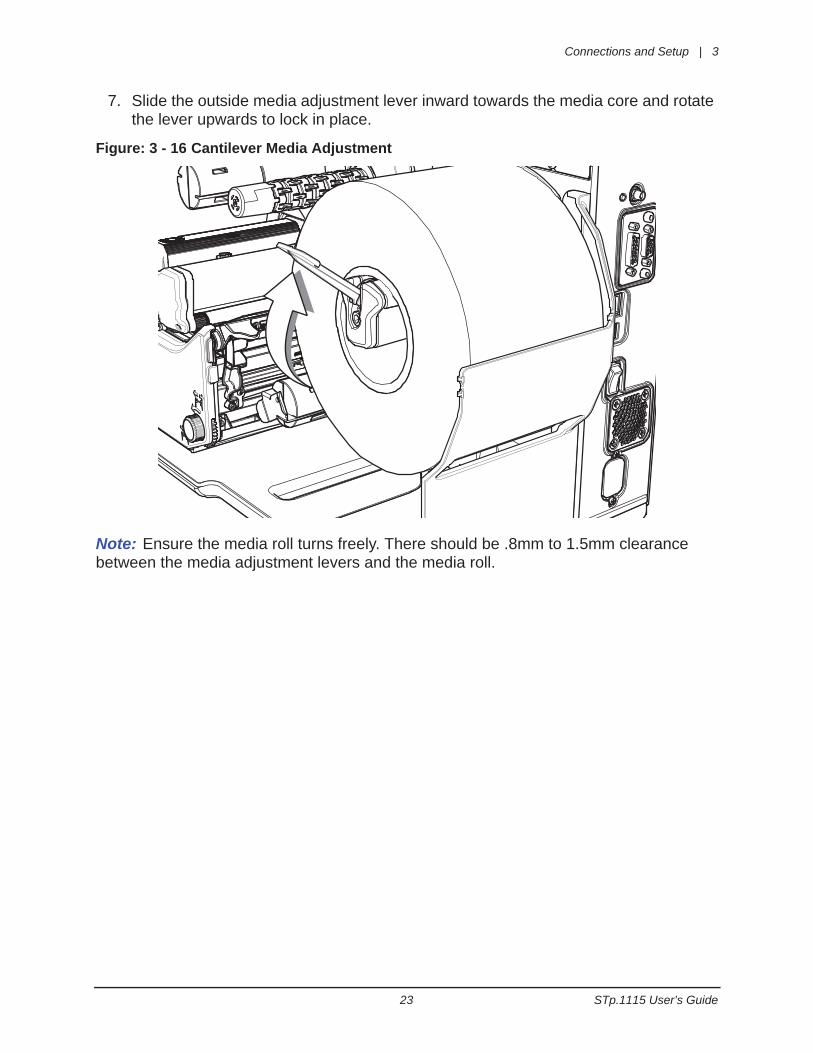
7. Slide the outside media adjustment lever inward towards the media core and rotate the lever upwards to lock in place.
Figure: 3 - 16 Cantilever Media Adjustment
Note: Ensure the media roll turns freely. There should be .8mm to 1.5mm clearance between the media adjustment levers and the media roll.
3 | Connections and Setup
STp.1115 User’s Guide 24
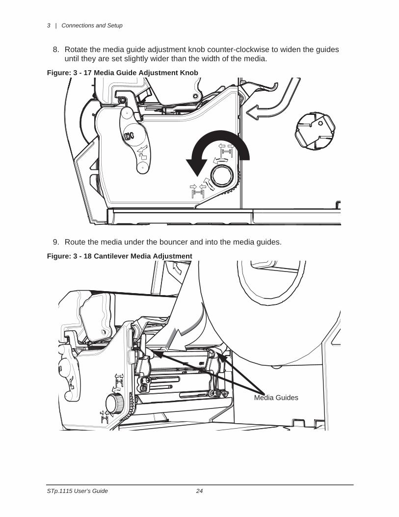
8. Rotate the media guide adjustment knob counter-clockwise to widen the guides until they are set slightly wider than the width of the media.
Figure: 3 - 17 Media Guide Adjustment Knob
9. Route the media under the bouncer and into the media guides.
Figure: 3 - 18 Cantilever Media Adjustment
Media Guides

Connections and Setup | 3
25 STp.1115 User’s Guide
10.Press the pinch roller knob and slide the media .25 inches beyond the pinch roller.
Figure: 3 - 19 Pinch Roller
11. Rotate the media guide adjustment knob clockwise to tighten the guides.
Note: Ensure the guides are neither too tight nor too loose on the media or print quality will be affected.
Figure: 3 - 20 Tighten Media Guide Adjustment Knob
Pinch Roller Knob Pinch Roller
3 | Connections and Setup
STp.1115 User’s Guide 26
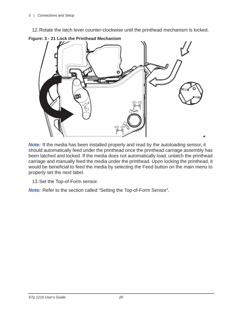
12.Rotate the latch lever counter-clockwise until the printhead mechanism is locked.
Figure: 3 - 21 Lock the Printhead Mechanism
Note: If the media has been installed properly and read by the autoloading sensor, it should automatically feed under the printhead once the printhead carriage assembly has been latched and locked. If the media does not automatically load, unlatch the printhead carriage and manually feed the media under the printhead. Upon locking the printhead, it would be beneficial to feed the media by selecting the Feed button on the main menu to properly set the next label.
13.Set the Top-of-Form sensor.
Note: Refer to the section called “Setting the Top-of-Form Sensor”.
Connections and Setup | 3
27 STp.1115 User’s Guide
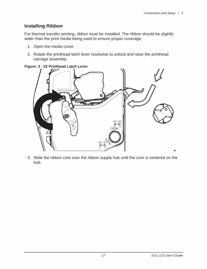
Installing RibbonFor thermal transfer printing, ribbon must be installed. The ribbon should be slightly wider than the print media being used to ensure proper coverage.
1. Open the media cover.
2. Rotate the printhead latch lever clockwise to unlock and raise the printhead carriage assembly.
Figure: 3 - 22 Printhead Latch Lever
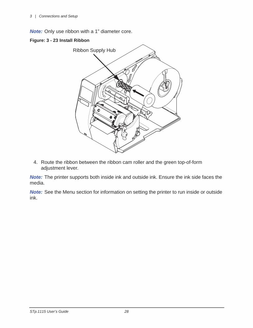
3. Slide the ribbon core over the ribbon supply hub until the core is centered on the hub.
3 | Connections and Setup
STp.1115 User’s Guide 28
Note: Only use ribbon with a 1” diameter core.
Figure: 3 - 23 Install Ribbon
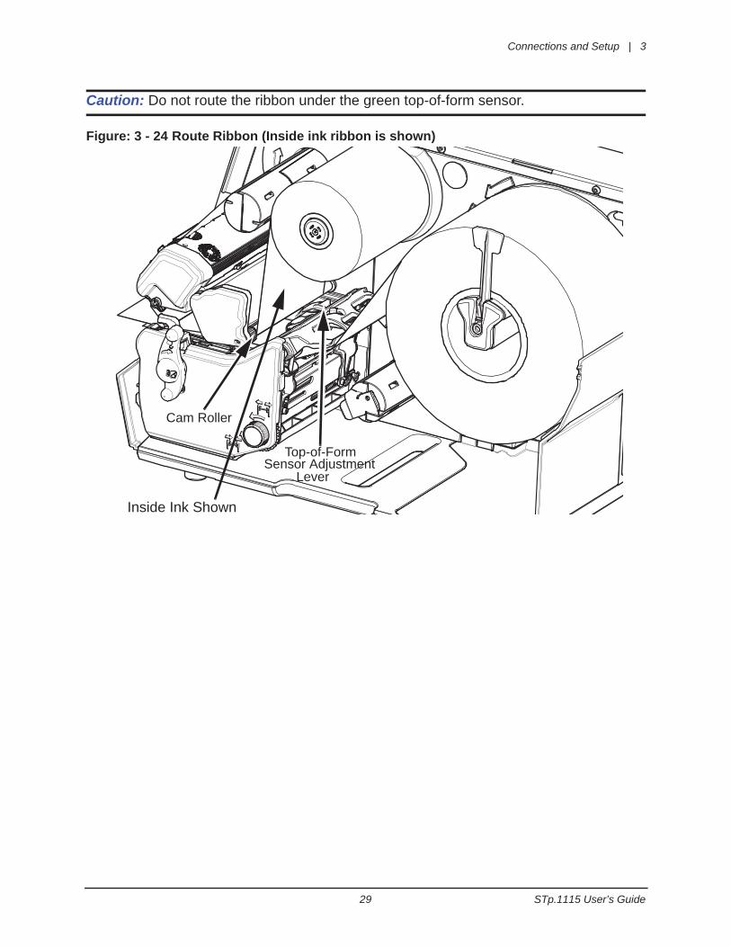
4. Route the ribbon between the ribbon cam roller and the green top-of-form adjustment lever.
Note: The printer supports both inside ink and outside ink. Ensure the ink side faces the media.
Note: See the Menu section for information on setting the printer to run inside or outside ink.
Ribbon Supply Hub
Connections and Setup | 3
29 STp.1115 User’s Guide
Caution: Do not route the ribbon under the green top-of-form sensor.
Figure: 3 - 24 Route Ribbon (Inside ink ribbon is shown)
Cam Roller
Top-of-FormSensor Adjustment
Inside Ink Shown
Lever
3 | Connections and Setup
STp.1115 User’s Guide 30
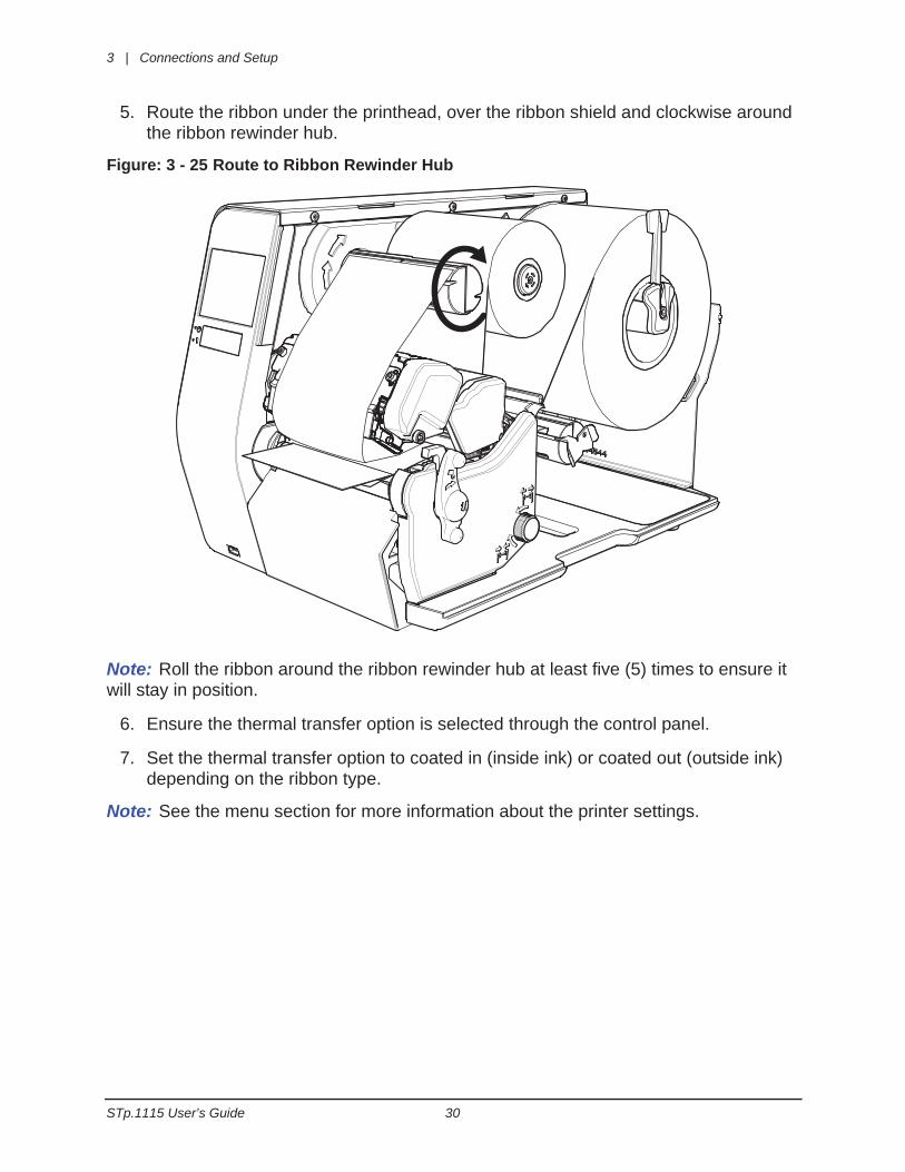
5. Route the ribbon under the printhead, over the ribbon shield and clockwise around the ribbon rewinder hub.
Figure: 3 - 25 Route to Ribbon Rewinder Hub
Note: Roll the ribbon around the ribbon rewinder hub at least five (5) times to ensure it will stay in position.
6. Ensure the thermal transfer option is selected through the control panel.
7. Set the thermal transfer option to coated in (inside ink) or coated out (outside ink) depending on the ribbon type.
Note: See the menu section for more information about the printer settings.
Connections and Setup | 3
31 STp.1115 User’s Guide
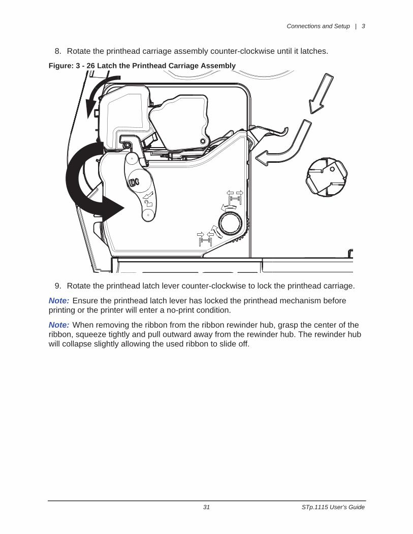
8. Rotate the printhead carriage assembly counter-clockwise until it latches.
Figure: 3 - 26 Latch the Printhead Carriage Assembly
9. Rotate the printhead latch lever counter-clockwise to lock the printhead carriage.
Note: Ensure the printhead latch lever has locked the printhead mechanism before printing or the printer will enter a no-print condition.
Note: When removing the ribbon from the ribbon rewinder hub, grasp the center of the ribbon, squeeze tightly and pull outward away from the rewinder hub. The rewinder hub will collapse slightly allowing the used ribbon to slide off.
3 | Connections and Setup
STp.1115 User’s Guide 32
Configuring Media and Ribbon SettingsOnce the media and ribbon have been loaded, the print parameters should be set to match the type of media and ribbon being used. This will ensure optimal print quality. Once set, the parameters will not need to be set again unless the media or ribbon types are changed.
Using Media and Ribbon IDs
Media and ribbons supplied by Source Technologies and other vendors may have a 4-digit media ID and ribbon ID assigned. These codes may be entered from the printer front panel. All relevant print parameters will be automatically configured.
1. Select Menu > Basic > Media > Enter ID.
2. Select the Enter Paper ID field and enter the appropriate 4-digit code.
3. Select the green Accept button to confirm your selection.
4. Select the Enter Ribbon ID field and enter the appropriate 4-digit code.
5. Select the green Accept button to confirm your selection.
6. After selecting the Home button, select the green Accept button to again confirm your selection or the red Reject button to cancel the changes.
Note: Although using media and ribbon IDs usually produce very good results, minor adjustments may be required. Refer to the section titled Adjusting Media and Ribbon Settings.
Selecting Media and Ribbon Types Manually
If media and ribbon IDs are not known, the media and ribbon types may be selected manually.
1. Select Menu > Basic > Media > Select Type.
2. Using the up and down arrows, select your paper type.
Note: If the paper type is not known, either select Coated Direct Thermal for direct thermal printing or select Coated Thermal Transfer for printing with a ribbon.
3. Tab to the Ribbon screen.
4. Using the up and down arrow, select your ribbon type.
Note: If the ribbon type is not known, select Wax to start. This selection can always be changed if required.
5. Tab to the Settings screen.
Connections and Setup | 3
33 STp.1115 User’s Guide
6. Select the Paper Sensor Type button until your paper type appears. The options are as follows:
• Gap
• Mark on Top
• Mark on Bottom
• Notch
• Continuous
Note: For more information, refer to the section Setting the Top-of-Form Sensor.
7. Select the Paper Sensor Side button until the correct option appears. The options are as follows:
• Outside
• Inside
Note: For more information, refer to the section Setting the Top-of-Form Sensor.
8. Select the Ribbon Mode button until the correct option appears. The options are as follows:
• None
• Coated In
• Coated Out
Note: For more information, refer to the section Setting the Top-of-Form Sensor.
Note: CSI ribbon (shiny side facing outward) should be installed where the ribbon unwinds in a counter-clockwise direction. CSO ribbon (dull side facing outward) should be installed where the ribbon unwinds in a clockwise direction. If these settings do not match the ribbon type being used, the ribbon supply hub will turn in the wrong direction.
Setting the Media and Ribbon Parameters Manually (Advanced)
There are times when all print parameters must be set manually. This can happen when a new or specialized media or ribbon are being used. This advanced procedure will use the Custom Manual utility.
Note: Some values may be grayed-out, meaning they are automatically set by default. To change these values, select the Auto button next to the value field and then select the green Accept button to confirm your choice to change to manual mode.
Note: Please see the Menu section for more information.
1. Select Menu > Advanced > Media.
2. Select the Paper Sensor Type field until the correct paper type appears. The options are as follows:
3 | Connections and Setup
STp.1115 User’s Guide 34
• Gap
• Mark on Top
• Mark on Bottom
• Notch
• Continuous
3. Select the Paper Sensor Side field until the correct option appears. The options are as follows:
• Outside
• Inside
4. Select the Ribbon Mode field until the correct option appears. The options are as follows:
• None
• Coated In
• Coated Out
5. Tab to the next screen and enter values for Heat and Heat Balance.
6. Tab to the next screen and enter values for Head Pressure and Rewinder Tension.
7. Tab to the next screen and enter values for Ribbon Tension Front and Ribbon Tension Rear.
8. Tab to the next screen and enter a value for Ribbon Low Diameter.
9. Select the Home button and select the green Accept button to confirm the settings.
Connections and Setup | 3
35 STp.1115 User’s Guide
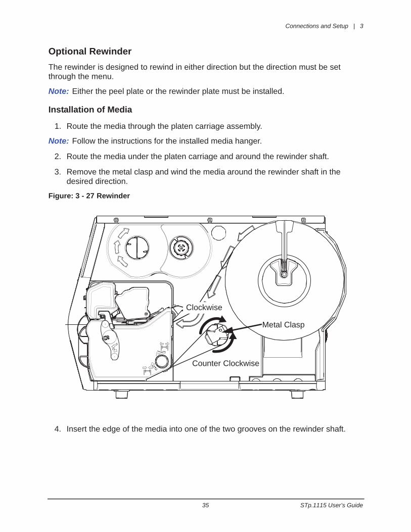
Optional RewinderThe rewinder is designed to rewind in either direction but the direction must be set through the menu.
Note: Either the peel plate or the rewinder plate must be installed.
Installation of Media
1. Route the media through the platen carriage assembly.
Note: Follow the instructions for the installed media hanger.
2. Route the media under the platen carriage and around the rewinder shaft.
3. Remove the metal clasp and wind the media around the rewinder shaft in the desired direction.
Figure: 3 - 27 Rewinder
4. Insert the edge of the media into one of the two grooves on the rewinder shaft.
Counter Clockwise
Clockwise
Metal Clasp
3 | Connections and Setup
STp.1115 User’s Guide 36
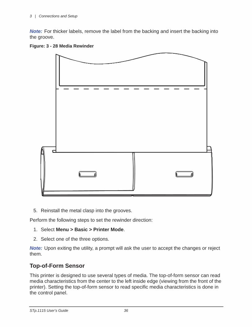
Note: For thicker labels, remove the label from the backing and insert the backing into the groove.
Figure: 3 - 28 Media Rewinder
5. Reinstall the metal clasp into the grooves.
Perform the following steps to set the rewinder direction:
1. Select Menu > Basic > Printer Mode.
2. Select one of the three options.
Note: Upon exiting the utility, a prompt will ask the user to accept the changes or reject them.
Top-of-Form SensorThis printer is designed to use several types of media. The top-of-form sensor can read media characteristics from the center to the left inside edge (viewing from the front of the printer). Setting the top-of-form sensor to read specific media characteristics is done in the control panel.
Connections and Setup | 3
37 STp.1115 User’s Guide
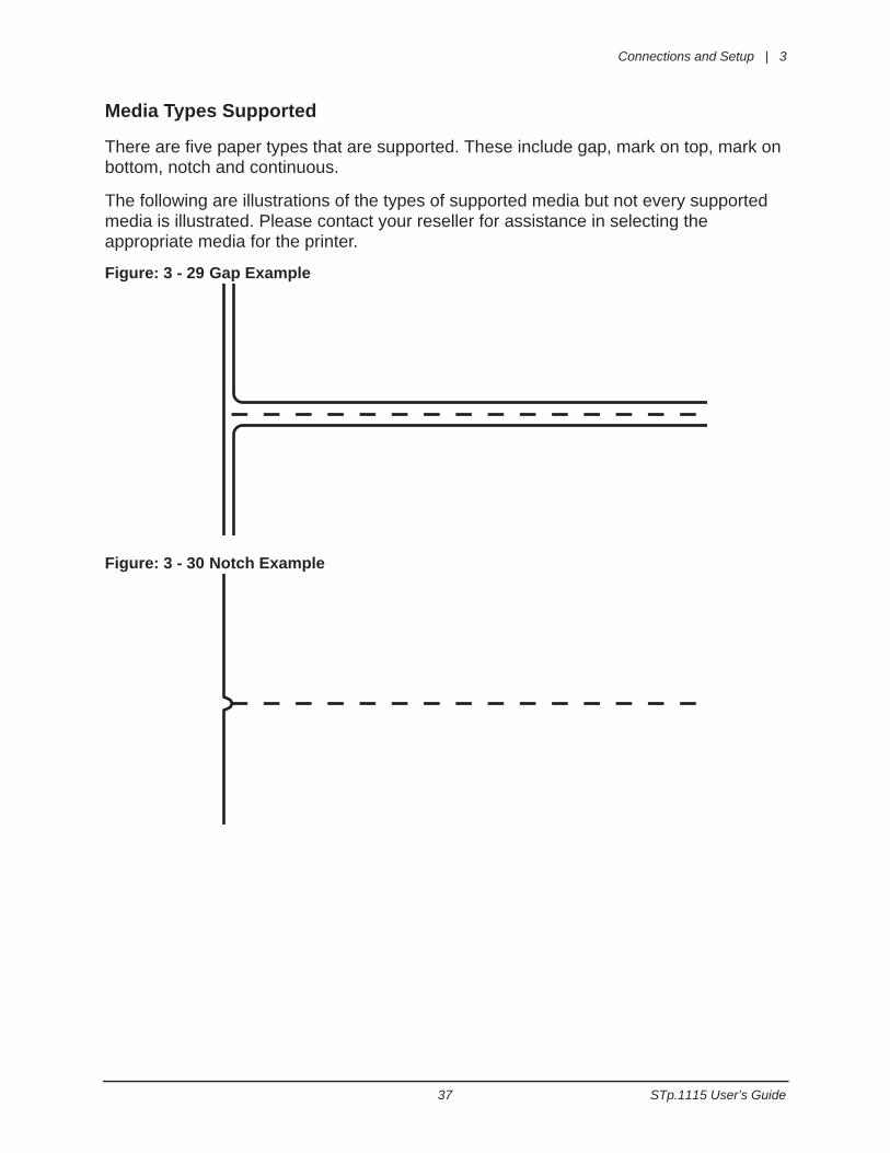
Media Types Supported
There are five paper types that are supported. These include gap, mark on top, mark on bottom, notch and continuous.
The following are illustrations of the types of supported media but not every supported media is illustrated. Please contact your reseller for assistance in selecting the appropriate media for the printer.
Figure: 3 - 29 Gap Example
Figure: 3 - 30 Notch Example
3 | Connections and Setup
STp.1115 User’s Guide 38
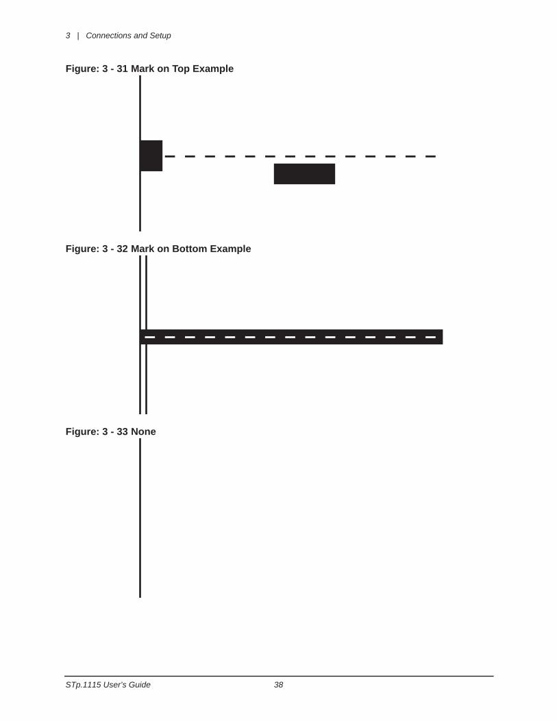
Figure: 3 - 31 Mark on Top Example
Figure: 3 - 32 Mark on Bottom Example
Figure: 3 - 33 None
Connections and Setup | 3
39 STp.1115 User’s Guide
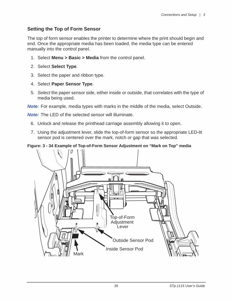
Setting the Top of Form Sensor
The top of form sensor enables the printer to determine where the print should begin and end. Once the appropriate media has been loaded, the media type can be entered manually into the control panel.
1. Select Menu > Basic > Media from the control panel.
2. Select Select Type.
3. Select the paper and ribbon type.
4. Select Paper Sensor Type.
5. Select the paper sensor side, either inside or outside, that correlates with the type of media being used.
Note: For example, media types with marks in the middle of the media, select Outside.
Note: The LED of the selected sensor will illuminate.
6. Unlock and release the printhead carriage assembly allowing it to open.
7. Using the adjustment lever, slide the top-of-form sensor so the appropriate LED-lit sensor pod is centered over the mark, notch or gap that was selected.
Figure: 3 - 34 Example of Top-of-Form Sensor Adjustment on “Mark on Top” media
MarkInside Sensor Pod
Outside Sensor Pod
Lever
Top-of-FormAdjustment

3 | Connections and Setup
STp.1115 User’s Guide 40
Note: For illustration purposes, the image of the printhead carriage assembly was removed in the image above. The LED sensor pods can be viewed from the front of the printer, under the printhead carriage assembly. The active sensor pod is lit by an LED.
Note: If the wrong pod is active for your media type, check your settings.
8. Close and lock the printhead carriage assembly.
Connections and Setup | 3
41 STp.1115 User’s Guide
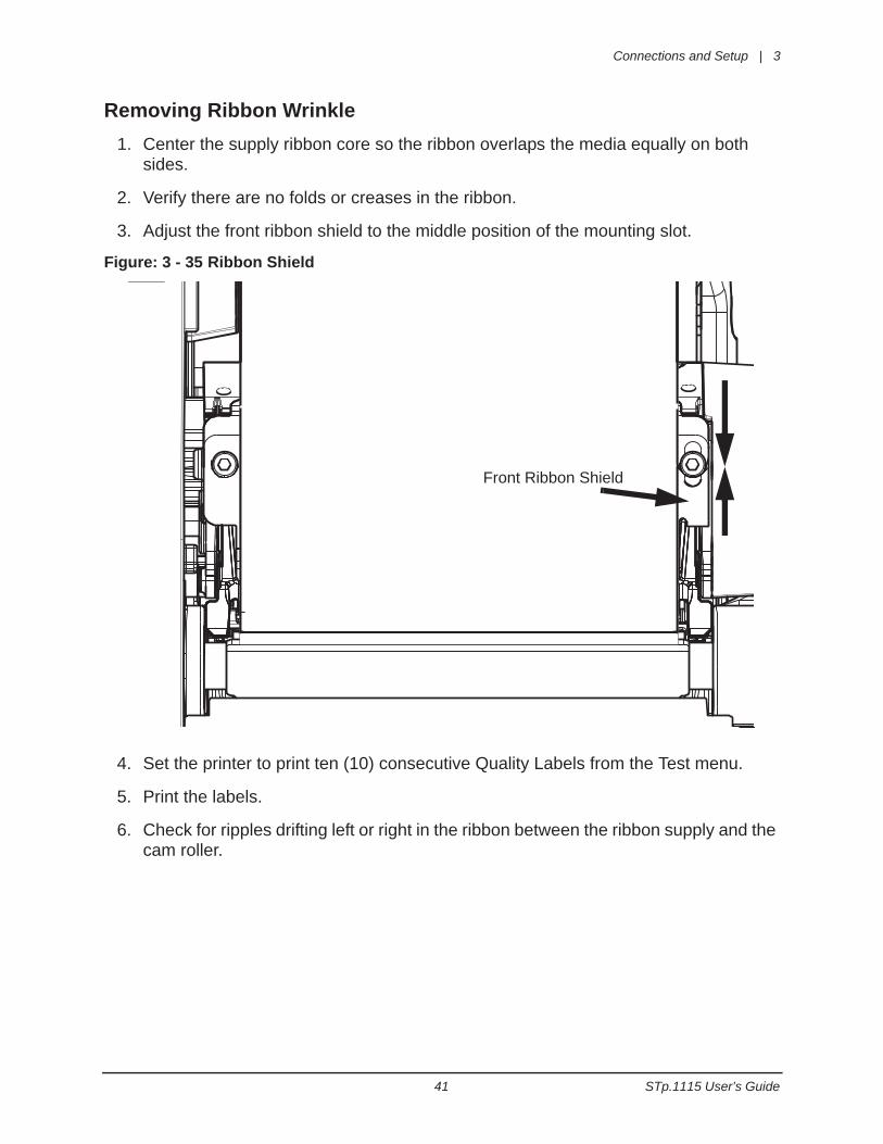
Removing Ribbon Wrinkle1. Center the supply ribbon core so the ribbon overlaps the media equally on both
sides.
2. Verify there are no folds or creases in the ribbon.
3. Adjust the front ribbon shield to the middle position of the mounting slot.
Figure: 3 - 35 Ribbon Shield
4. Set the printer to print ten (10) consecutive Quality Labels from the Test menu.
5. Print the labels.
6. Check for ripples drifting left or right in the ribbon between the ribbon supply and the cam roller.
Front Ribbon Shield
3 | Connections and Setup
STp.1115 User’s Guide 42
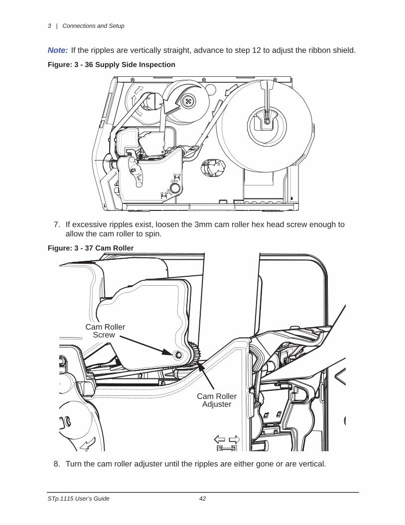
Note: If the ripples are vertically straight, advance to step 12 to adjust the ribbon shield.
Figure: 3 - 36 Supply Side Inspection
7. If excessive ripples exist, loosen the 3mm cam roller hex head screw enough to allow the cam roller to spin.
Figure: 3 - 37 Cam Roller
8. Turn the cam roller adjuster until the ripples are either gone or are vertical.
Cam RollerScrew
Cam RollerAdjuster
Connections and Setup | 3
43 STp.1115 User’s Guide
Note: The ripples must never drift left or right.
9. Tighten the cam roller screw.
10.Print ten (10) Quality Labels from the test menu.
Note: If wrinkles still appear continue with the adjustment procedure.
11. Loosen the ribbon shield adjustment screws.
12.While printing test labels, slowly adjust the lower shield until the ribbon tension is constant from left to right and the wrinkles disappear.
Note: Adjust the ribbon shield by adding tension to the side with wrinkling or light print.
Note: Adjustment should eliminate side-to-side wrinkles.
Manual Head Pressure AdjustmentThe printer calculates the ribbon and media settings and then suggests the optimal printhead pressure. If the current printhead pressure setting is different from the suggested setting, a prompt will appear on the menu screen suggesting that the head pressure should be adjusted.
1. Select Info > Extended Status from the home screen.
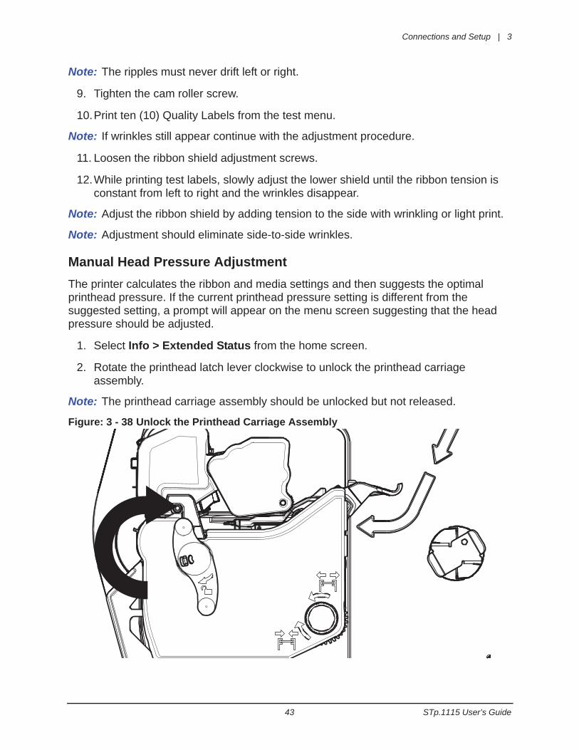
2. Rotate the printhead latch lever clockwise to unlock the printhead carriage assembly.
Note: The printhead carriage assembly should be unlocked but not released.
Figure: 3 - 38 Unlock the Printhead Carriage Assembly
3 | Connections and Setup
STp.1115 User’s Guide 44
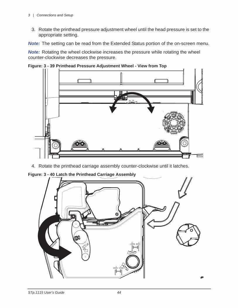
3. Rotate the printhead pressure adjustment wheel until the head pressure is set to the appropriate setting.
Note: The setting can be read from the Extended Status portion of the on-screen menu.
Note: Rotating the wheel clockwise increases the pressure while rotating the wheel counter-clockwise decreases the pressure.
Figure: 3 - 39 Printhead Pressure Adjustment Wheel - View from Top
4. Rotate the printhead carriage assembly counter-clockwise until it latches.
Figure: 3 - 40 Latch the Printhead Carriage Assembly
Connections and Setup | 3
45 STp.1115 User’s Guide
Installing Cutter and Tray
Warning: To prevent serious injury, never place a finger or object other than media near the cutter mechanism.
Caution: Never cut paper or media in an area where adhesives exist. Doing so willdamage the cutter and void the manufacturer’s warranty.
Caution: The media cover will not close with both the cutter and present sensor installedat the same time for those printers with a present sensor installed in the cover..
Caution: The printer must be powered off and disconnected from AC utility power priorto the cutter installation.
The cutter and cutting tray are available options that must be installed after receiving the printer.
Cutter
Perform the following procedure to install the cutter.
Note: The printer and the cutter tray must be on the same level surface.
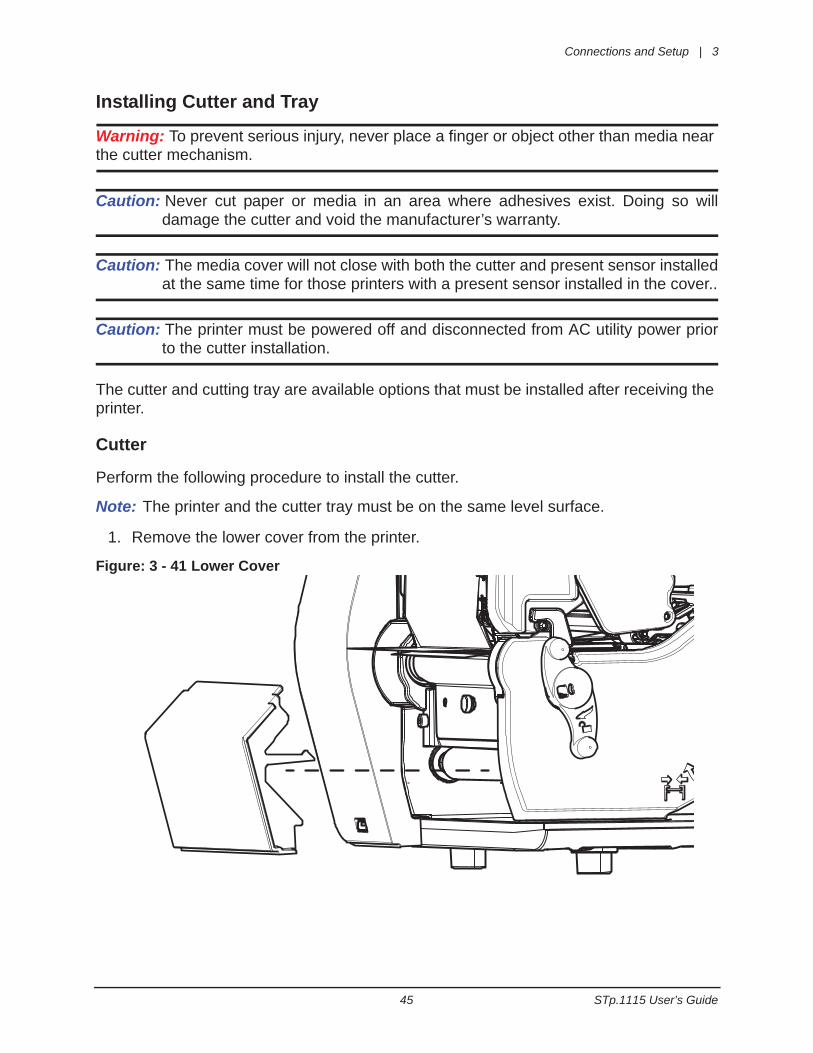
1. Remove the lower cover from the printer.
Figure: 3 - 41 Lower Cover
3 | Connections and Setup
STp.1115 User’s Guide 46
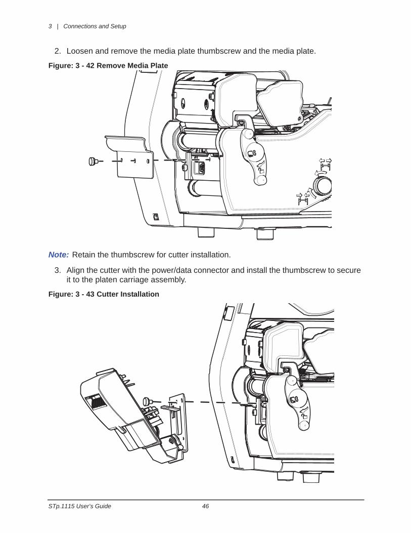
2. Loosen and remove the media plate thumbscrew and the media plate.
Figure: 3 - 42 Remove Media Plate
Note: Retain the thumbscrew for cutter installation.
3. Align the cutter with the power/data connector and install the thumbscrew to secure it to the platen carriage assembly.
Figure: 3 - 43 Cutter Installation
Connections and Setup | 3
47 STp.1115 User’s Guide
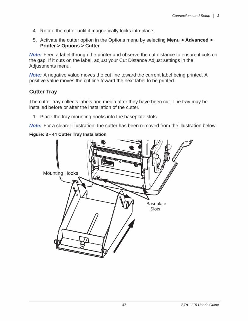
4. Rotate the cutter until it magnetically locks into place.
5. Activate the cutter option in the Options menu by selecting Menu > Advanced > Printer > Options > Cutter.
Note: Feed a label through the printer and observe the cut distance to ensure it cuts on the gap. If it cuts on the label, adjust your Cut Distance Adjust settings in the Adjustments menu.
Note: A negative value moves the cut line toward the current label being printed. A positive value moves the cut line toward the next label to be printed.
Cutter Tray
The cutter tray collects labels and media after they have been cut. The tray may be installed before or after the installation of the cutter.
1. Place the tray mounting hooks into the baseplate slots.
Note: For a clearer illustration, the cutter has been removed from the illustration below.
Figure: 3 - 44 Cutter Tray Installation
Mounting Hooks
BaseplateSlots

3 | Connections and Setup
STp.1115 User’s Guide 48
Print Driver Installation
Overview
This section is intended to instruct the user about the installation of the Performance Series Print Driver Setup Utility on a Windows® -based computer. The Setup Utility is installed and used to successfully install the print driver for USB or network-connected printers.
This installation should be executed only on a computer where no printer driver or print driver utility has been installed unless otherwise noted.
The installer should note the following:
• The printer driver files are installed into the Windows print system so when a USB printer is connected or a network printer is added, the system will automatically recognize the printer and install the driver for it.
• The print driver utility is installed as a Windows program on the computer. The util-ity is a Windows program that can be accessed at any time to add additional Per-formance Series printers.
Requirements
The Performance Series print driver setup is supported on the following 32-bit or 64-bit operating systems:
• Windows XP
• Windows Vista
• Windows 7
• Windows Server 2003
• Windows Server 2008
• Windows Server 2008 R2
Connections and Setup | 3
49 STp.1115 User’s Guide
Installation Instructions
Downloading the Performance Series Print Driver From the Website
Note: The installation file is also accessible from the product CD that shipped with the printer.
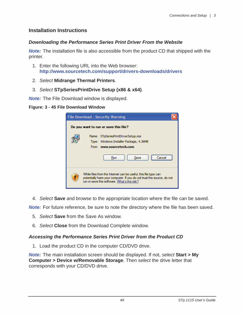
1. Enter the following URL into the Web browser:http://www.sourcetech.com/support/drivers-downloads/drivers
2. Select Midrange Thermal Printers.
3. Select STpSeriesPrintDrive Setup (x86 & x64).
Note: The File Download window is displayed.
Figure: 3 - 45 File Download Window
4. Select Save and browse to the appropriate location where the file can be saved.
Note: For future reference, be sure to note the directory where the file has been saved.
5. Select Save from the Save As window.
6. Select Close from the Download Complete window.
Accessing the Performance Series Print Driver from the Product CD
1. Load the product CD in the computer CD/DVD drive.
Note: The main installation screen should be displayed. If not, select Start > My Computer > Device w/Removable Storage. Then select the drive letter that corresponds with your CD/DVD drive.
3 | Connections and Setup
STp.1115 User’s Guide 50
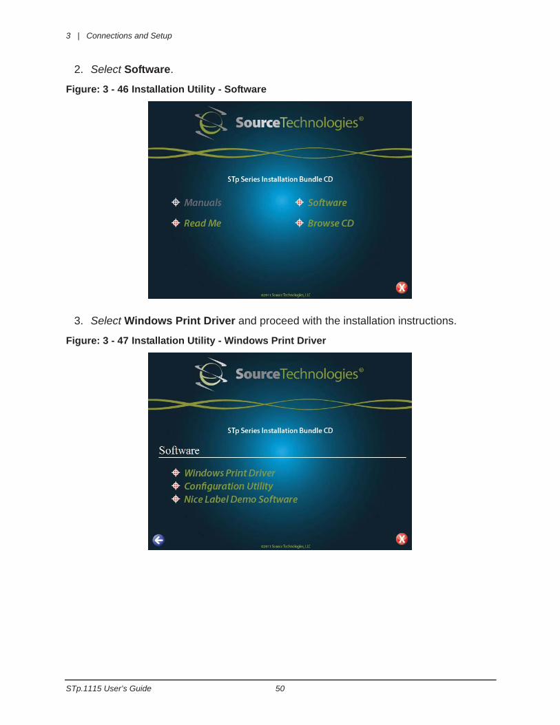
2. Select Software.
Figure: 3 - 46 Installation Utility - Software
3. Select Windows Print Driver and proceed with the installation instructions.
Figure: 3 - 47 Installation Utility - Windows Print Driver
Connections and Setup | 3
51 STp.1115 User’s Guide
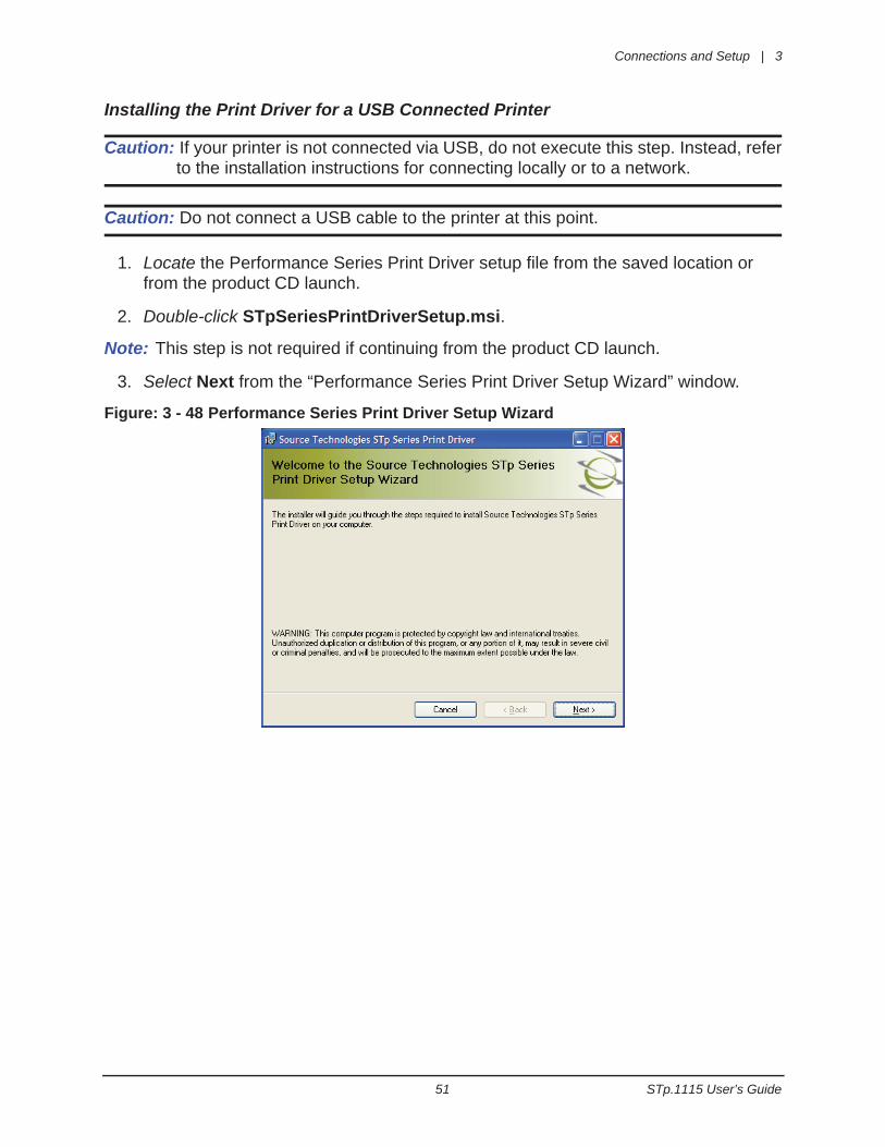
Installing the Print Driver for a USB Connected Printer
Caution: If your printer is not connected via USB, do not execute this step. Instead, referto the installation instructions for connecting locally or to a network.
Caution: Do not connect a USB cable to the printer at this point.
1. Locate the Performance Series Print Driver setup file from the saved location or from the product CD launch.
2. Double-click STpSeriesPrintDriverSetup.msi.
Note: This step is not required if continuing from the product CD launch.
3. Select Next from the “Performance Series Print Driver Setup Wizard” window.
Figure: 3 - 48 Performance Series Print Driver Setup Wizard
3 | Connections and Setup
STp.1115 User’s Guide 52
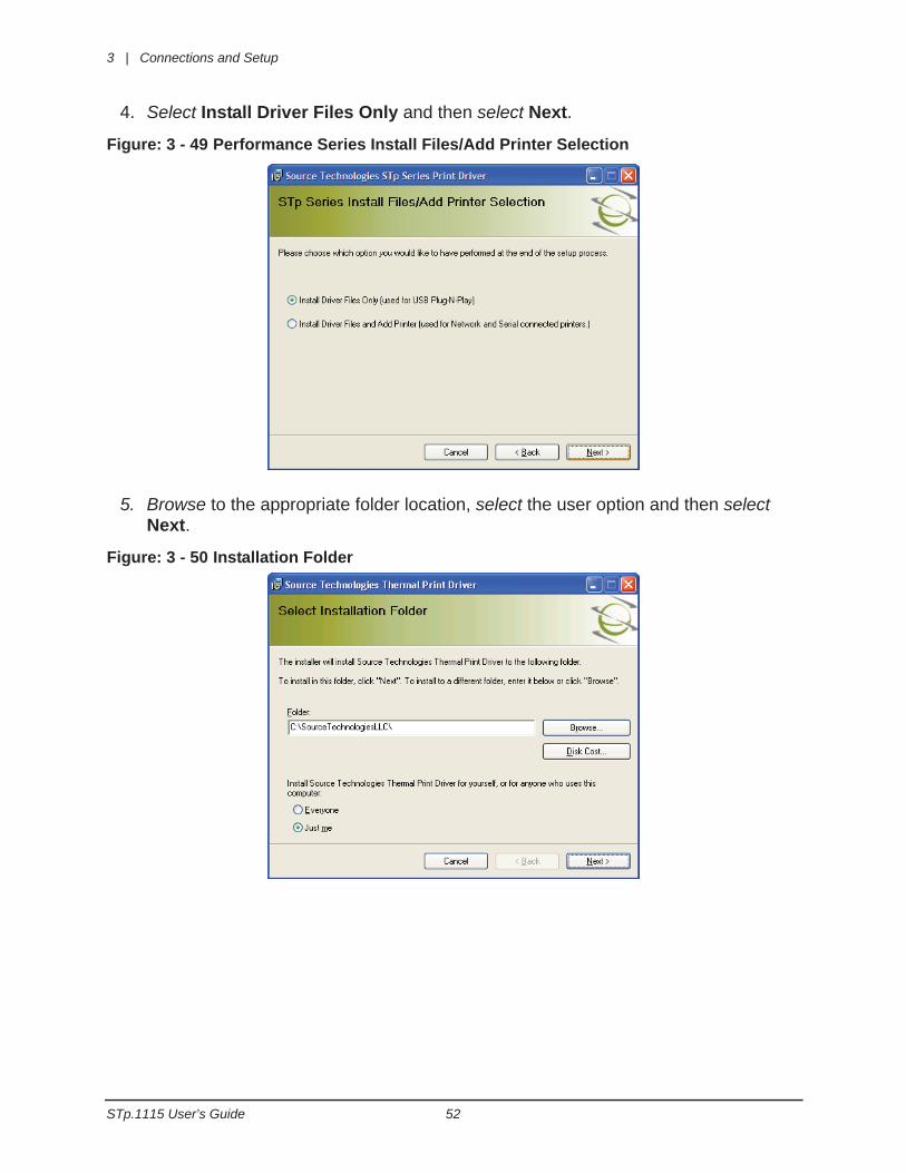
4. Select Install Driver Files Only and then select Next.
Figure: 3 - 49 Performance Series Install Files/Add Printer Selection
5. Browse to the appropriate folder location, select the user option and then select Next.
Figure: 3 - 50 Installation Folder
Connections and Setup | 3
53 STp.1115 User’s Guide
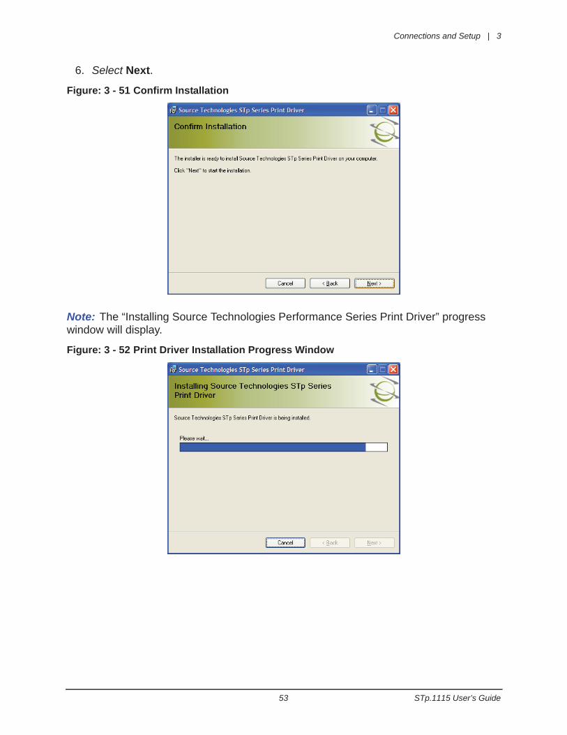
6. Select Next.
Figure: 3 - 51 Confirm Installation
Note: The “Installing Source Technologies Performance Series Print Driver” progress window will display.
Figure: 3 - 52 Print Driver Installation Progress Window
3 | Connections and Setup
STp.1115 User’s Guide 54
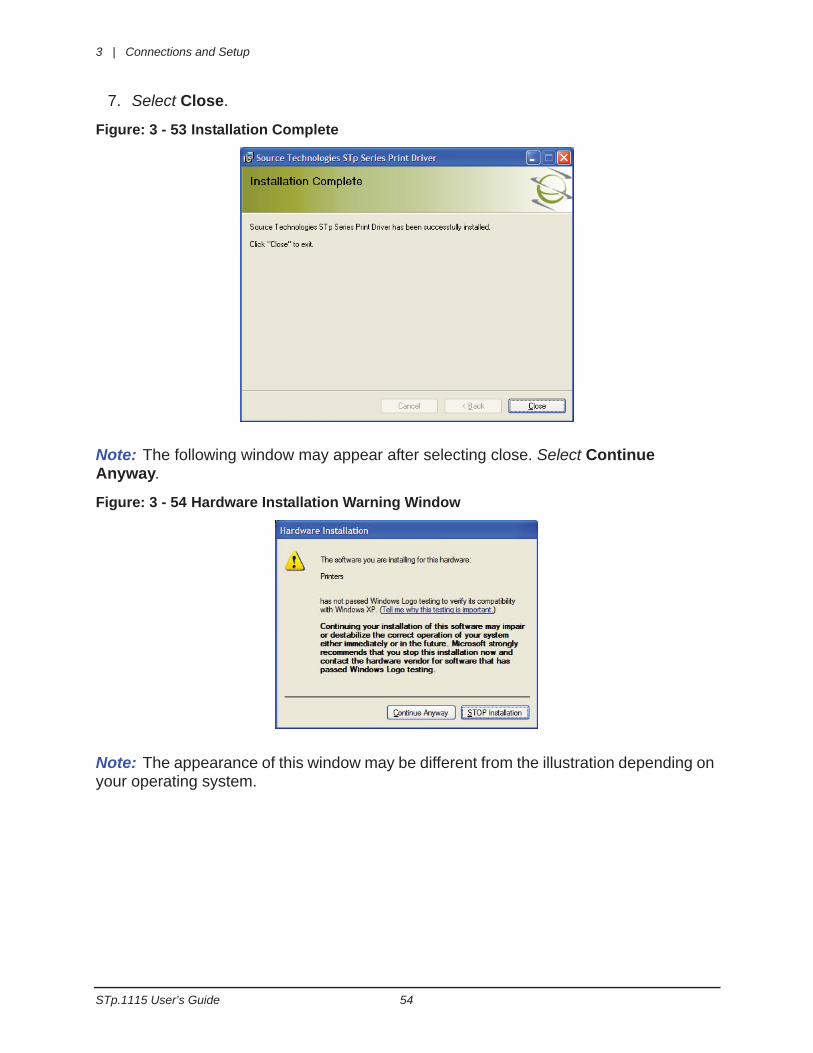
7. Select Close.
Figure: 3 - 53 Installation Complete
Note: The following window may appear after selecting close. Select Continue Anyway.
Figure: 3 - 54 Hardware Installation Warning Window
Note: The appearance of this window may be different from the illustration depending on your operating system.
Connections and Setup | 3
55 STp.1115 User’s Guide
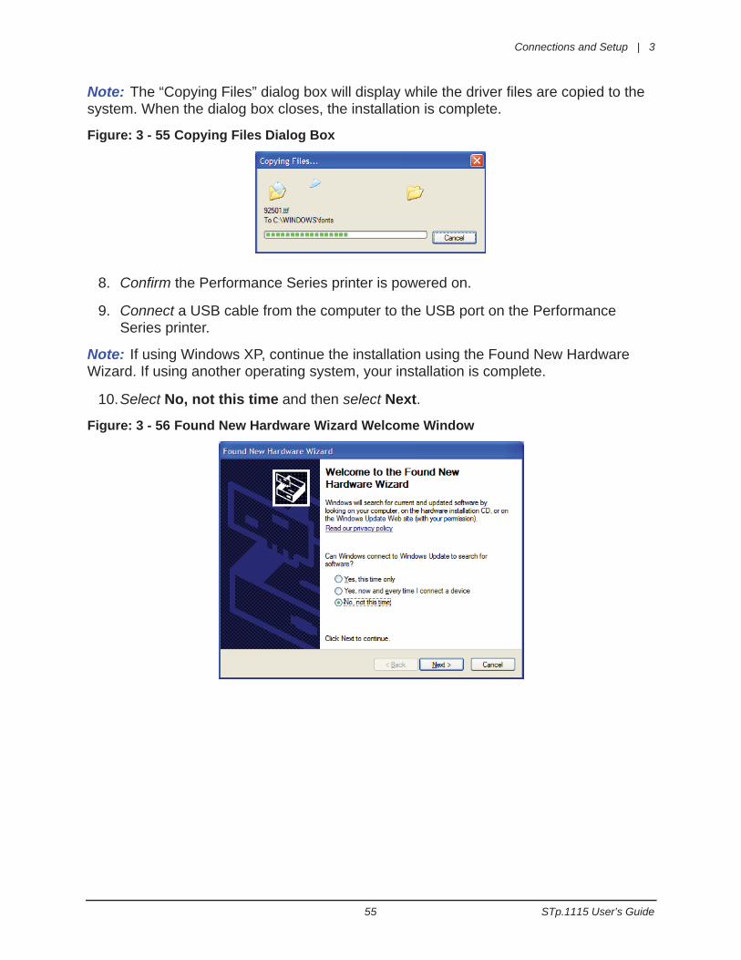
Note: The “Copying Files” dialog box will display while the driver files are copied to the system. When the dialog box closes, the installation is complete.
Figure: 3 - 55 Copying Files Dialog Box
8. Confirm the Performance Series printer is powered on.
9. Connect a USB cable from the computer to the USB port on the Performance Series printer.
Note: If using Windows XP, continue the installation using the Found New Hardware Wizard. If using another operating system, your installation is complete.
10.Select No, not this time and then select Next.
Figure: 3 - 56 Found New Hardware Wizard Welcome Window
3 | Connections and Setup
STp.1115 User’s Guide 56
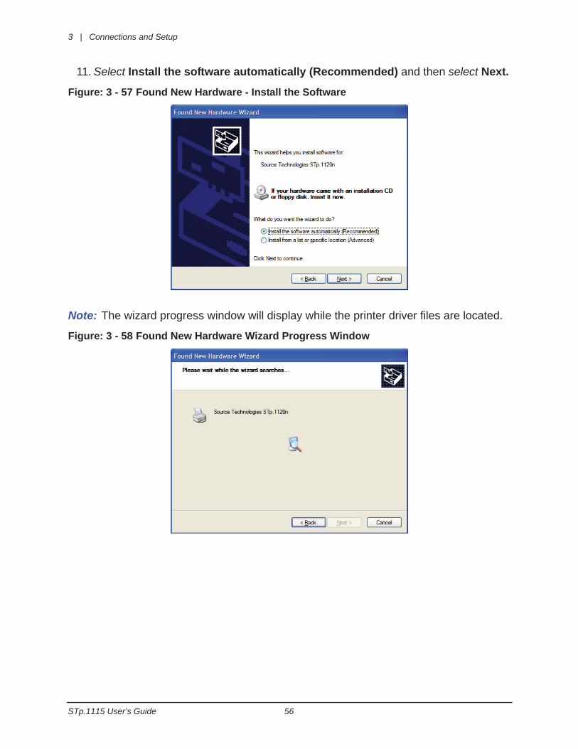
11. Select Install the software automatically (Recommended) and then select Next.
Figure: 3 - 57 Found New Hardware - Install the Software
Note: The wizard progress window will display while the printer driver files are located.
Figure: 3 - 58 Found New Hardware Wizard Progress Window
Connections and Setup | 3
57 STp.1115 User’s Guide
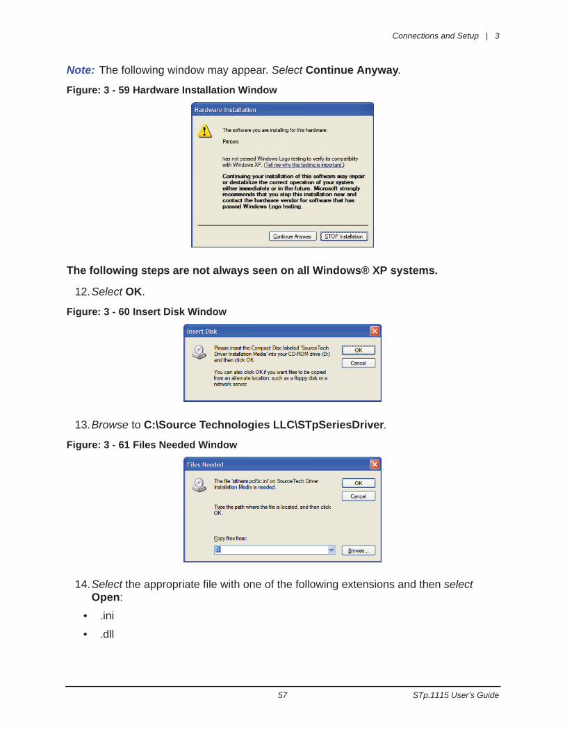
Note: The following window may appear. Select Continue Anyway.
Figure: 3 - 59 Hardware Installation Window
The following steps are not always seen on all Windows® XP systems.
12.Select OK.
Figure: 3 - 60 Insert Disk Window
13.Browse to C:\Source Technologies LLC\STpSeriesDriver.
Figure: 3 - 61 Files Needed Window
14.Select the appropriate file with one of the following extensions and then select Open:
• .ini
• .dll
3 | Connections and Setup
STp.1115 User’s Guide 58
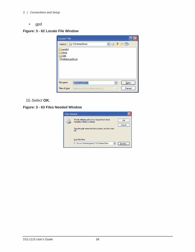
• .gpd
Figure: 3 - 62 Locate File Window
15.Select OK.
Figure: 3 - 63 Files Needed Window
Connections and Setup | 3
59 STp.1115 User’s Guide
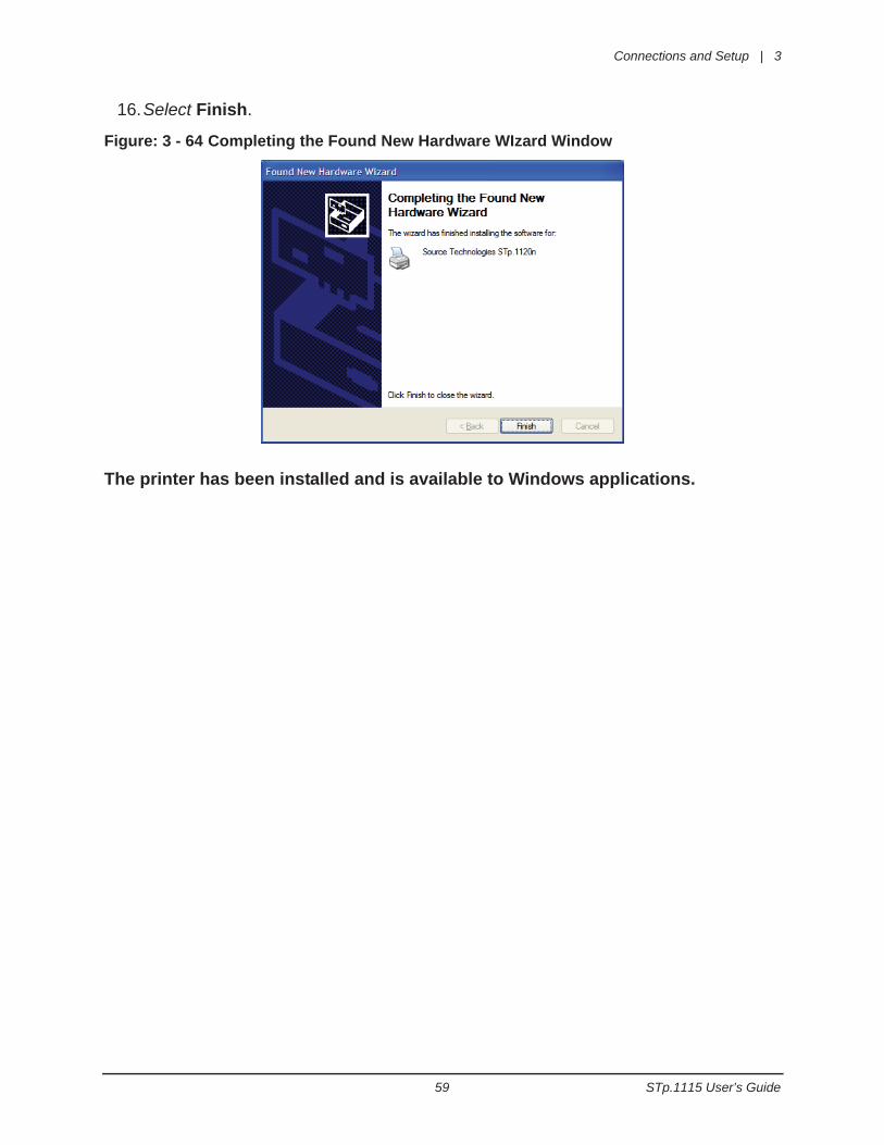
16.Select Finish.
Figure: 3 - 64 Completing the Found New Hardware WIzard Window
The printer has been installed and is available to Windows applications.
3 | Connections and Setup
STp.1115 User’s Guide 60
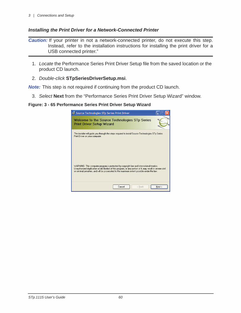
Installing the Print Driver for a Network-Connected Printer
Caution: If your printer in not a network-connected printer, do not execute this step.Instead, refer to the installation instructions for installing the print driver for aUSB connected printer.”
1. Locate the Performance Series Print Driver Setup file from the saved location or the product CD launch.
2. Double-click STpSeriesDriverSetup.msi.
Note: This step is not required if continuing from the product CD launch.
3. Select Next from the “Performance Series Print Driver Setup Wizard” window.
Figure: 3 - 65 Performance Series Print Driver Setup Wizard
Connections and Setup | 3
61 STp.1115 User’s Guide
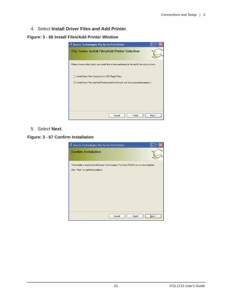
4. Select Install Driver Files and Add Printer.
Figure: 3 - 66 Install Files/Add Printer WIndow
5. Select Next.
Figure: 3 - 67 Confirm Installation
3 | Connections and Setup
STp.1115 User’s Guide 62
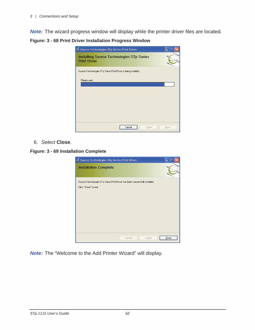
Note: The wizard progress window will display while the printer driver files are located.
Figure: 3 - 68 Print Driver Installation Progress Window
6. Select Close.
Figure: 3 - 69 Installation Complete
Note: The “Welcome to the Add Printer Wizard” will display.
Connections and Setup | 3
63 STp.1115 User’s Guide
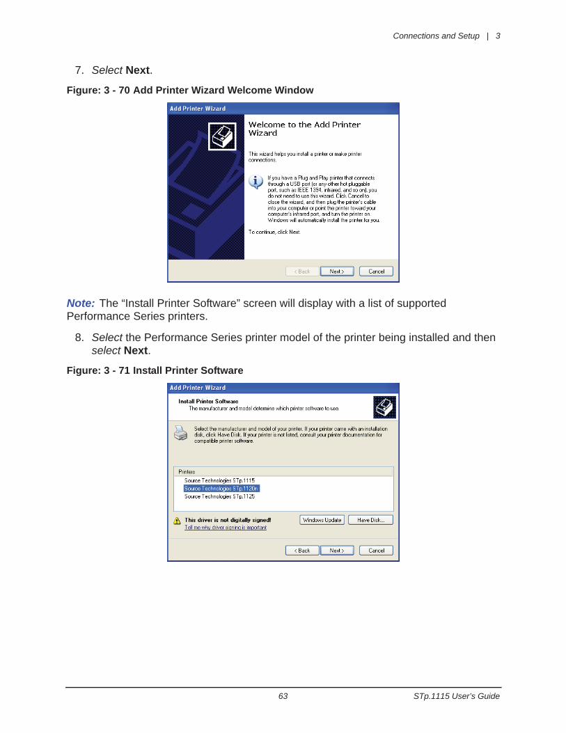
7. Select Next.
Figure: 3 - 70 Add Printer Wizard Welcome Window
Note: The “Install Printer Software” screen will display with a list of supported Performance Series printers.
8. Select the Performance Series printer model of the printer being installed and then select Next.
Figure: 3 - 71 Install Printer Software
3 | Connections and Setup
STp.1115 User’s Guide 64
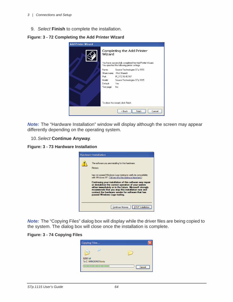
9. Select Finish to complete the installation.
Figure: 3 - 72 Completing the Add Printer WIzard
Note: The “Hardware Installation” window will display although the screen may appear differently depending on the operating system.
10.Select Continue Anyway.
Figure: 3 - 73 Hardware Installation
Note: The “Copying Files” dialog box will display while the driver files are being copied to the system. The dialog box will close once the installation is complete.
Figure: 3 - 74 Copying Files

Connections and Setup | 3
65 STp.1115 User’s Guide
Note: The screenshot may appear different from the illustration depending on the operating system being used.
Once the installation is complete, the printer is available to Windows applications.
3 | Connections and Setup
STp.1115 User’s Guide 66
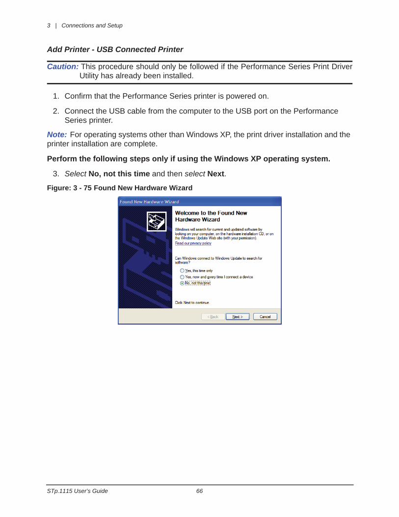
Add Printer - USB Connected Printer
Caution: This procedure should only be followed if the Performance Series Print DriverUtility has already been installed.
1. Confirm that the Performance Series printer is powered on.
2. Connect the USB cable from the computer to the USB port on the Performance Series printer.
Note: For operating systems other than Windows XP, the print driver installation and the printer installation are complete.
Perform the following steps only if using the Windows XP operating system.
3. Select No, not this time and then select Next.
Figure: 3 - 75 Found New Hardware Wizard
Connections and Setup | 3
67 STp.1115 User’s Guide
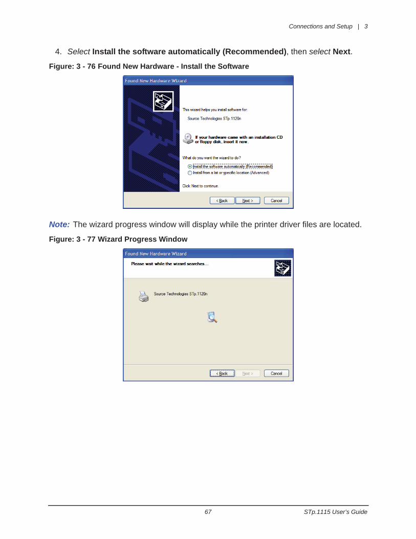
4. Select Install the software automatically (Recommended), then select Next.
Figure: 3 - 76 Found New Hardware - Install the Software
Note: The wizard progress window will display while the printer driver files are located.
Figure: 3 - 77 Wizard Progress Window
3 | Connections and Setup
STp.1115 User’s Guide 68
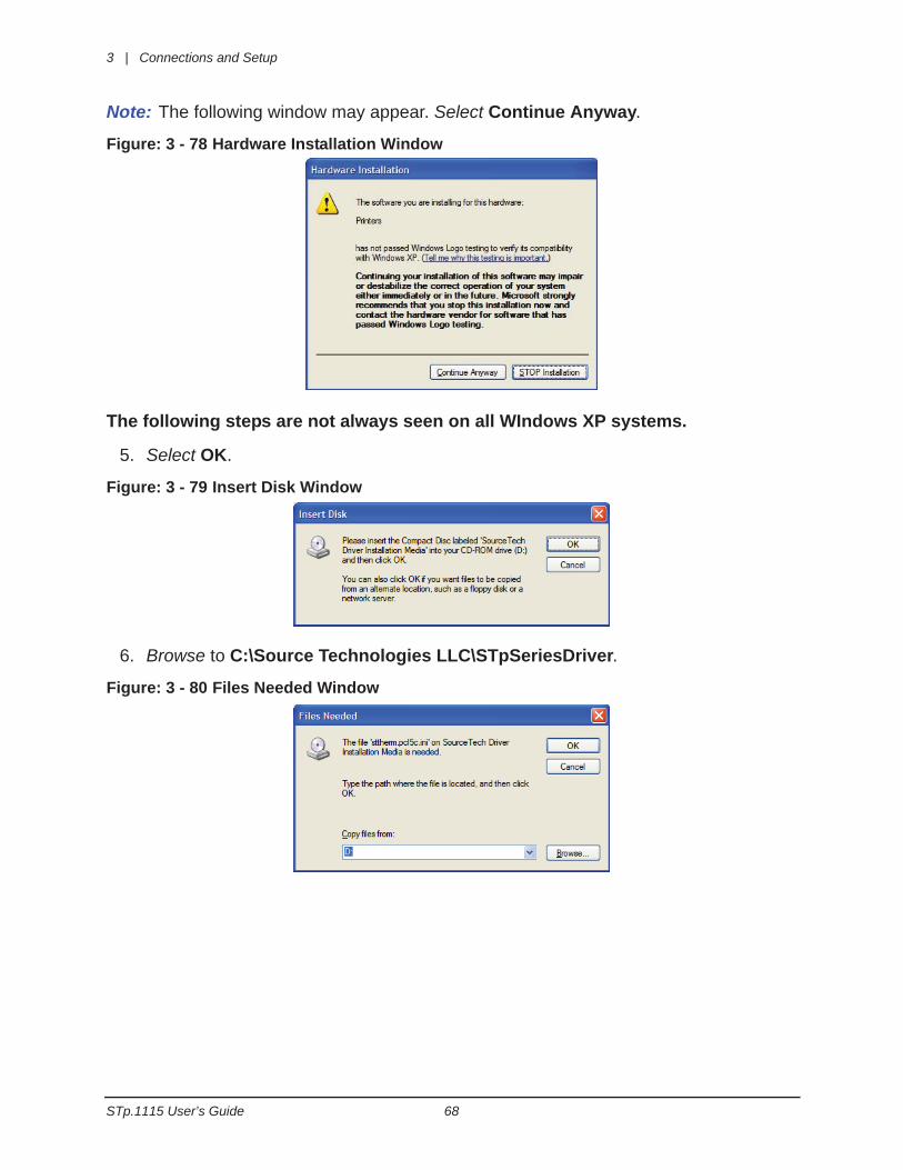
Note: The following window may appear. Select Continue Anyway.
Figure: 3 - 78 Hardware Installation Window
The following steps are not always seen on all WIndows XP systems.
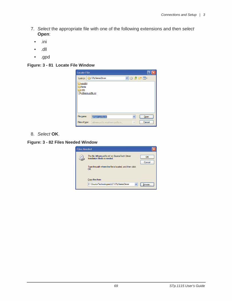
5. Select OK.
Figure: 3 - 79 Insert Disk Window
6. Browse to C:\Source Technologies LLC\STpSeriesDriver.
Figure: 3 - 80 Files Needed Window
Connections and Setup | 3
69 STp.1115 User’s Guide
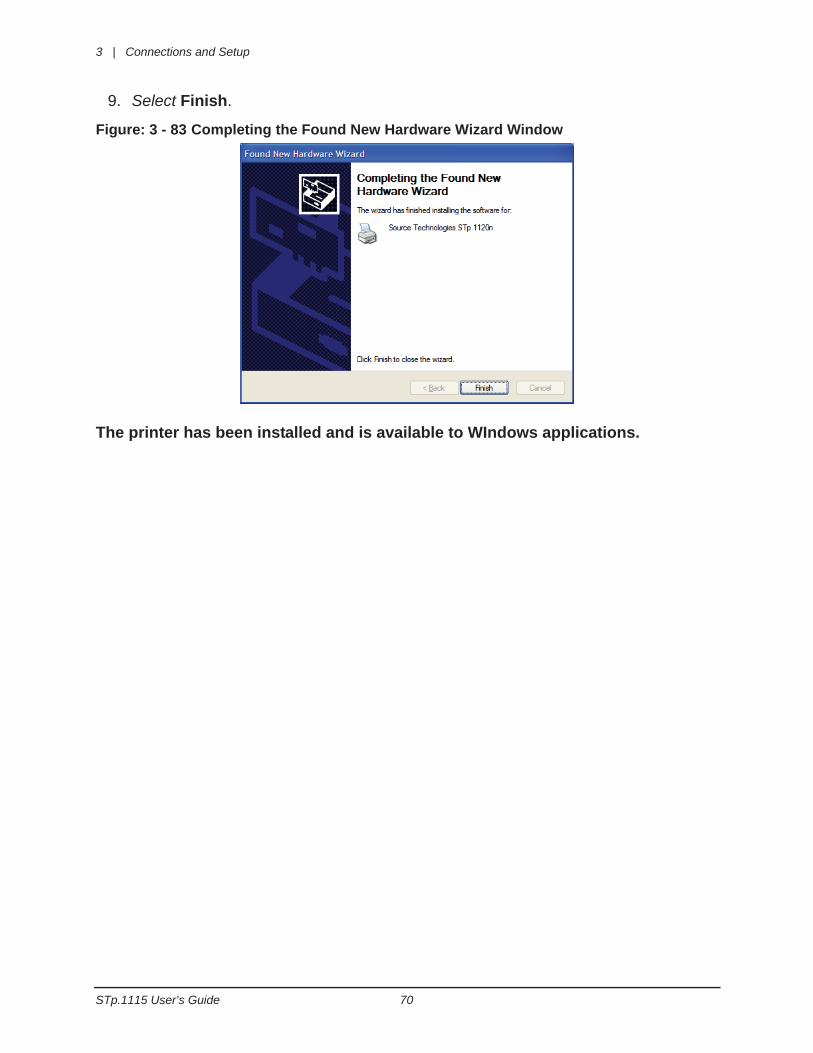
7. Select the appropriate file with one of the following extensions and then select Open:
• .ini
• .dll
• .gpd
Figure: 3 - 81 Locate File Window
8. Select OK.
Figure: 3 - 82 Files Needed Window
3 | Connections and Setup
STp.1115 User’s Guide 70
9. Select Finish.
Figure: 3 - 83 Completing the Found New Hardware Wizard Window
The printer has been installed and is available to WIndows applications.
Connections and Setup | 3
71 STp.1115 User’s Guide
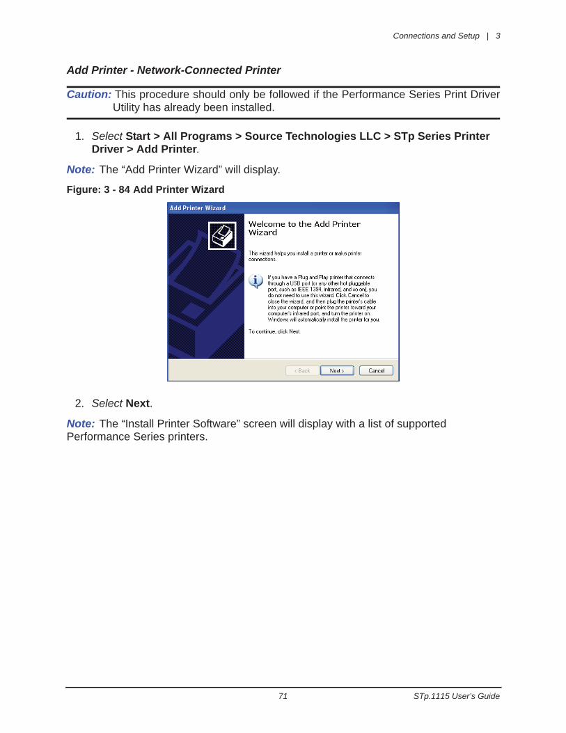
Add Printer - Network-Connected Printer
Caution: This procedure should only be followed if the Performance Series Print DriverUtility has already been installed.
1. Select Start > All Programs > Source Technologies LLC > STp Series Printer Driver > Add Printer.
Note: The “Add Printer Wizard” will display.
Figure: 3 - 84 Add Printer Wizard
2. Select Next.
Note: The “Install Printer Software” screen will display with a list of supported Performance Series printers.
3 | Connections and Setup
STp.1115 User’s Guide 72
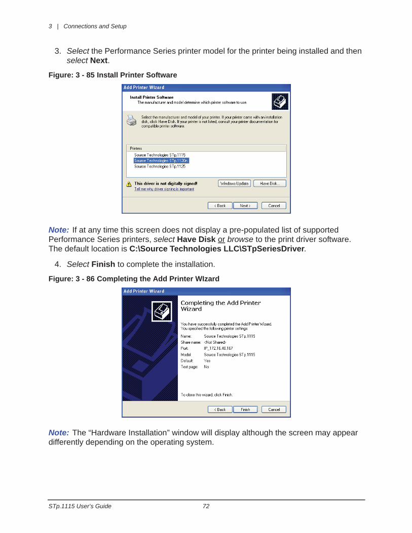
3. Select the Performance Series printer model for the printer being installed and then select Next.
Figure: 3 - 85 Install Printer Software
Note: If at any time this screen does not display a pre-populated list of supported Performance Series printers, select Have Disk or browse to the print driver software. The default location is C:\Source Technologies LLC\STpSeriesDriver.
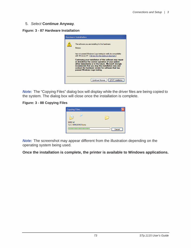
4. Select Finish to complete the installation.
Figure: 3 - 86 Completing the Add Printer WIzard
Note: The “Hardware Installation” window will display although the screen may appear differently depending on the operating system.
Connections and Setup | 3
73 STp.1115 User’s Guide
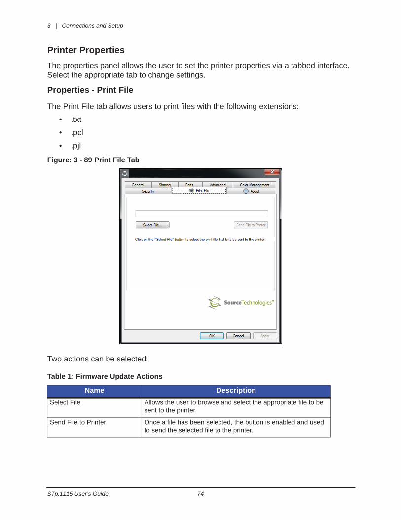
5. Select Continue Anyway.
Figure: 3 - 87 Hardware Installation
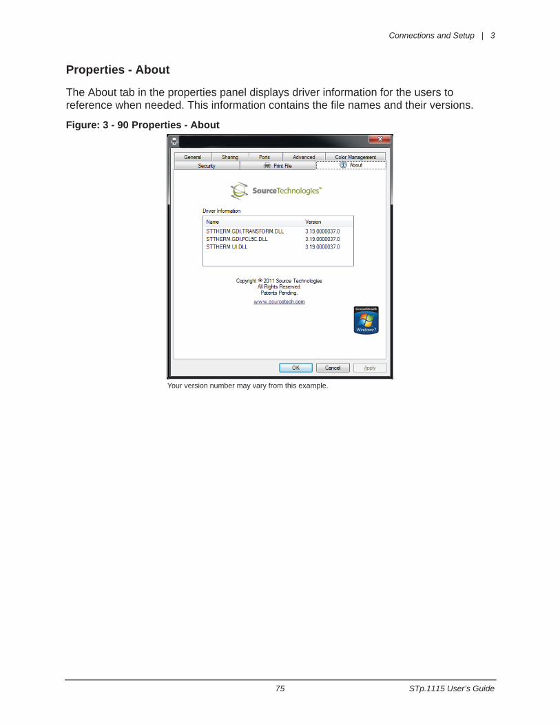
Note: The “Copying Files” dialog box will display while the driver files are being copied to the system. The dialog box will close once the installation is complete.
Figure: 3 - 88 Copying Files
Note: The screenshot may appear different from the illustration depending on the operating system being used.
Once the installation is complete, the printer is available to Windows applications.
3 | Connections and Setup
STp.1115 User’s Guide 74
Printer PropertiesThe properties panel allows the user to set the printer properties via a tabbed interface. Select the appropriate tab to change settings.
Properties - Print File
The Print File tab allows users to print files with the following extensions:
• .txt
• .pcl
• .pjl
Figure: 3 - 89 Print File Tab
Two actions can be selected:
Table 1: Firmware Update Actions
Name DescriptionSelect File Allows the user to browse and select the appropriate file to be
sent to the printer.
Send File to Printer Once a file has been selected, the button is enabled and used to send the selected file to the printer.
Connections and Setup | 3
75 STp.1115 User’s Guide
Properties - About
The About tab in the properties panel displays driver information for the users to reference when needed. This information contains the file names and their versions.
Figure: 3 - 90 Properties - About
Your version number may vary from this example.
3 | Connections and Setup
STp.1115 User’s Guide 76
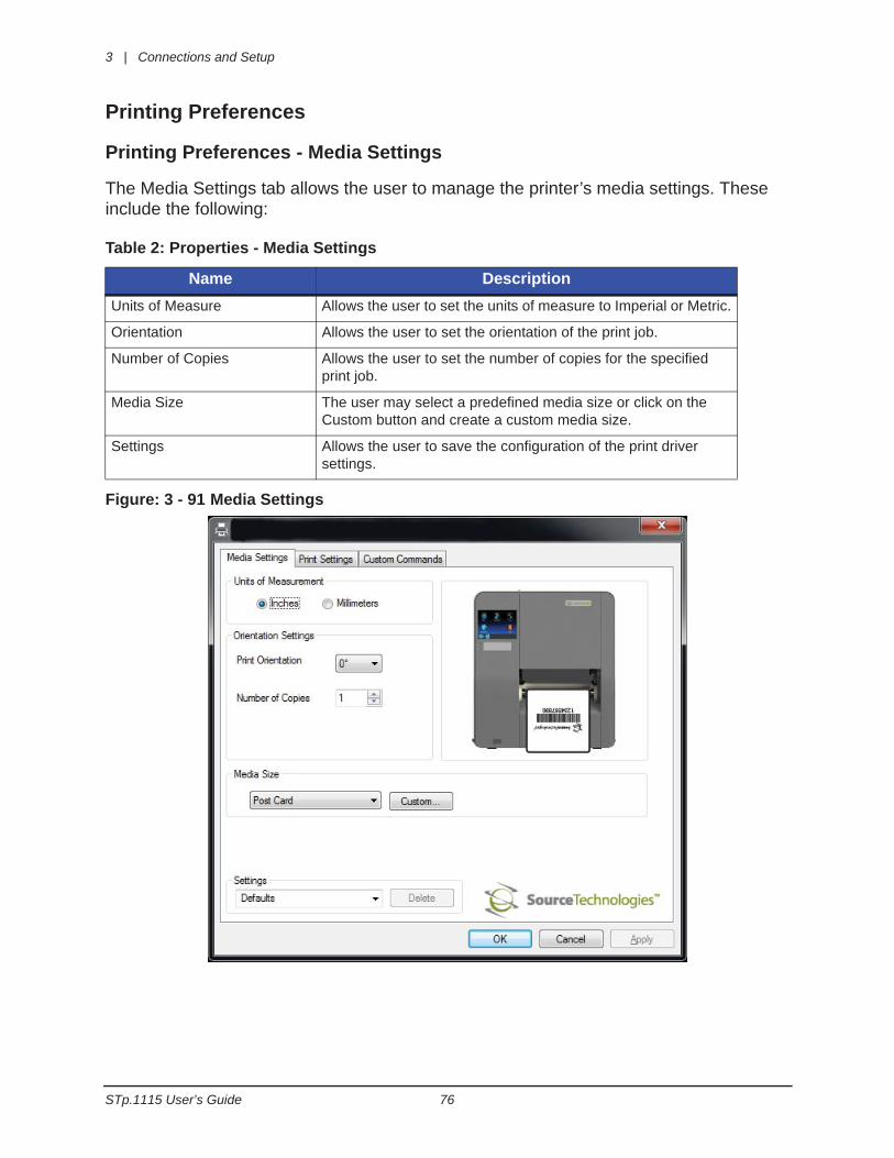
Printing Preferences
Printing Preferences - Media Settings
The Media Settings tab allows the user to manage the printer’s media settings. These include the following:
Table 2: Properties - Media Settings
Figure: 3 - 91 Media Settings
Name DescriptionUnits of Measure Allows the user to set the units of measure to Imperial or Metric.
Orientation Allows the user to set the orientation of the print job.
Number of Copies Allows the user to set the number of copies for the specified print job.
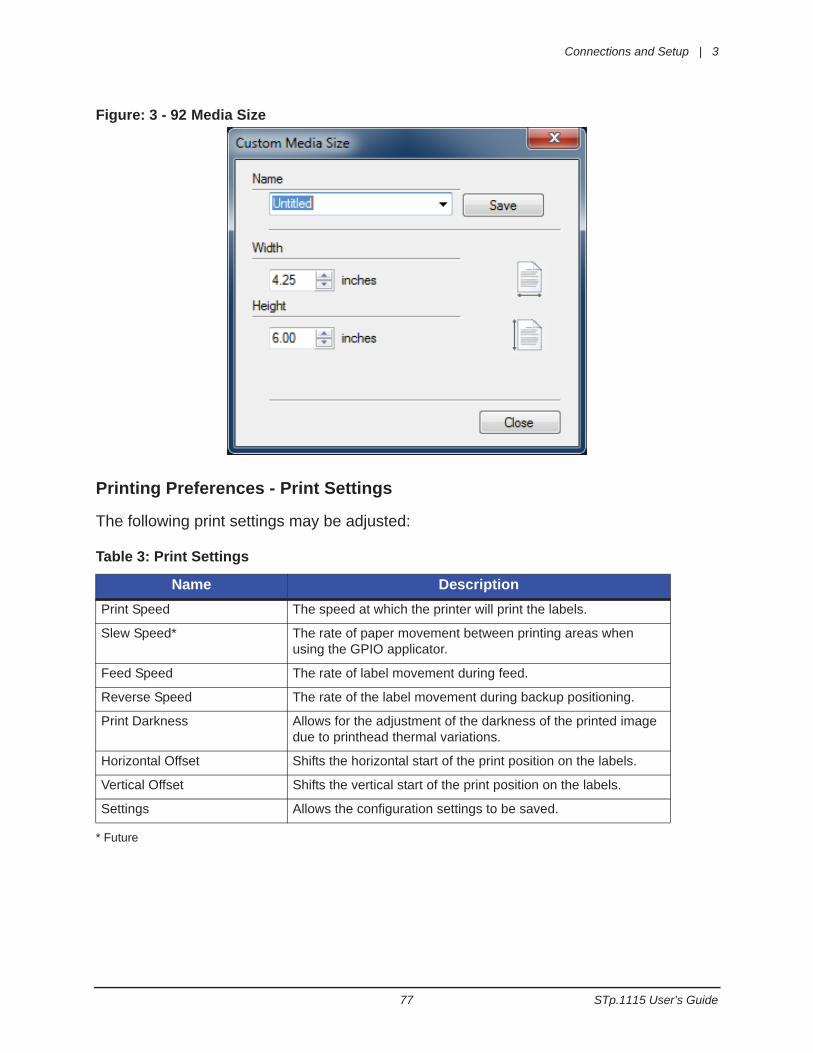
Media Size The user may select a predefined media size or click on the Custom button and create a custom media size.
Settings Allows the user to save the configuration of the print driver settings.
Connections and Setup | 3
77 STp.1115 User’s Guide
Figure: 3 - 92 Media Size
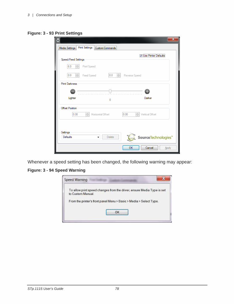
Printing Preferences - Print Settings
The following print settings may be adjusted:
Table 3: Print Settings
* Future
Name DescriptionPrint Speed The speed at which the printer will print the labels.
Slew Speed* The rate of paper movement between printing areas when using the GPIO applicator.
Feed Speed The rate of label movement during feed.
Reverse Speed The rate of the label movement during backup positioning.
Print Darkness Allows for the adjustment of the darkness of the printed image due to printhead thermal variations.
Horizontal Offset Shifts the horizontal start of the print position on the labels.
Vertical Offset Shifts the vertical start of the print position on the labels.
Settings Allows the configuration settings to be saved.
3 | Connections and Setup
STp.1115 User’s Guide 78
Figure: 3 - 93 Print Settings
Whenever a speed setting has been changed, the following warning may appear:
Figure: 3 - 94 Speed Warning
Connections and Setup | 3
79 STp.1115 User’s Guide
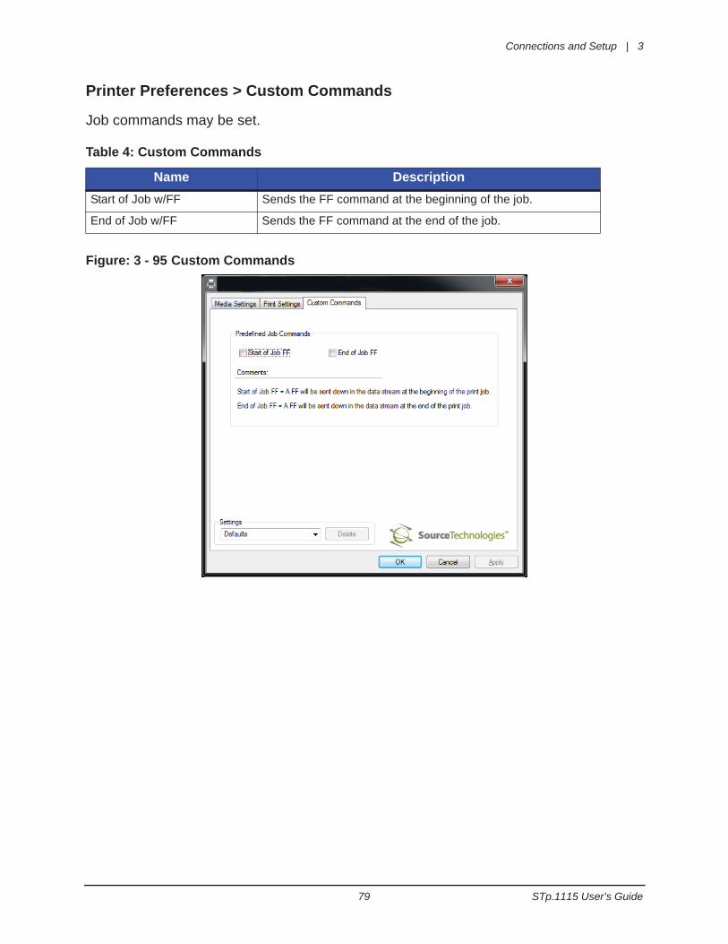
Printer Preferences > Custom Commands
Job commands may be set.
Table 4: Custom Commands
Figure: 3 - 95 Custom Commands
Name DescriptionStart of Job w/FF Sends the FF command at the beginning of the job.
End of Job w/FF Sends the FF command at the end of the job.

3 | Connections and Setup
STp.1115 User’s Guide 80
81 STp.1115 User’s Guide
4 Menu System
Menu OverviewThe printer is designed with a touchscreen display. Functions can be enabled and disabled and settings can be changed through the on-screen menu. Press the buttons on the screen with the light touch of a finger.
Caution: Do not touch the screen with excessive force or by using sharp objects. Doingso will damage the touchscreen and may void the manufacturer’s warranty.
Layout of the DisplayNavigationThe menu screens have buttons for advancing or returning to screens.
Back ButtonThe Back button provides the user with the option to return to a previous menu screen.
Home ButtonSelecting the Home button sends the user to the main screen.
Tabbed BrowsingBlue left and right arrow buttons are provided at the bottom right of the screen to navigate tabbed menus. Select the right arrow to advance to the next tab or the left arrow to return to the previous tab.
ScrollingSome menu screens allow for scrolling. Select the appropriate up or down arrow.
Changing ValuesNumeric values can be entered or changed by selecting the field and entering the values using the numeric keypad. They can also be increased or decreased using the subsequent plus or minus buttons.Other menu options are changed by pressing the button until the appropriate selection appears.
4 | Menu System
STp.1115 User’s Guide 82
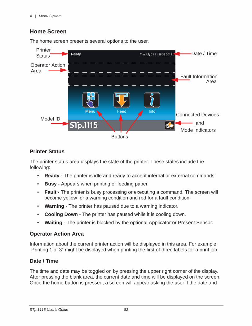
Home ScreenThe home screen presents several options to the user.
Printer Status
The printer status area displays the state of the printer. These states include the following:
• Ready - The printer is idle and ready to accept internal or external commands.
• Busy - Appears when printing or feeding paper.
• Fault - The printer is busy processing or executing a command. The screen will become yellow for a warning condition and red for a fault condition.
• Warning - The printer has paused due to a warning indicator.
• Cooling Down - The printer has paused while it is cooling down.
• Waiting - The printer is blocked by the optional Applicator or Present Sensor.
Operator Action Area
Information about the current printer action will be displayed in this area. For example, “Printing 1 of 3” might be displayed when printing the first of three labels for a print job.
Date / Time
The time and date may be toggled on by pressing the upper right corner of the display. After pressing the blank area, the current date and time will be displayed on the screen. Once the home button is pressed, a screen will appear asking the user if the date and
Ready
Menu Feed Info
Thu July 21 11:58:33 2012PrinterStatus
Buttons
Date / Time
Operator Action
Fault Information
Model IDConnected Devices
Area
Area
andMode Indicators
Menu System | 4
83 STp.1115 User’s Guide
time will be displayed. Select the green Accept button to display the time or the red Reject button to cancel.
Fault Information Area
Warnings and faults will be displayed in this area. Once the fault has been corrected, the message will disappear.
Connected Devices
The symbol for devices connected to the USB host will be presented in this area.
Mode Indicators
The printer will display modes that have been activated. If options have been installed but not enabled, they will not appear in this area of the display.
Information Button By selecting the information button from the task bar, the following information can be accessed.
• System Info
• Settings Report
• Network Report
• Extended Status
• Serial Report
• Applicator Report
• Fonts Report
System Information
The following will be displayed upon selection of the System Info button:
• Printer Model
• Software Version
• Firmware Version
• Ribbon Version
• Boot Version
• Board ID
• RAM Size
• Flash Size
• Security Key
4 | Menu System
STp.1115 User’s Guide 84
• Printer Odometer
• Paper Type
• Ribbon Type
• Detected Options
Note: Selecting the down or up arrow will display additional information.
Settings Report
The settings report provides information on the printer settings.
Media Settings• Paper Sensor Type
• Paper Sensor Side
• Ribbon Mode
• Heat
• Heat Balance
• Head Pressure
• Rewinder Tension
• Ribbon Tension Front
• Ribbon Tension Rear
• Ribbon Low Diameter
Printer Settings• Cutter Mode
• Rewinder Mode
• Present Sensor Enable
• Print Speed
• Feed Speed
• Reverse Speed
• Present Distance
• Disable Paper Low Warning
• Disable Paper Out Warning
• Disable Cover Open Warning
• Reprint on Error
• Present Timeout
Menu System | 4
85 STp.1115 User’s Guide
Page Defaults Settings• Print Length
• Print Width
• Vertical Offset
• Horizontal Offset
• Orientation
• Raster Mode
• Font Name (Number)
• Point Size
• Pitch Size
• Symbol Set
• Print Truncation
• Print on Gap/Mark
Auto Settings• Auto Load
• Auto Option Detect
• Auto Calibrate
• Auto Present Distance
• Auto Tension
• Suggested Pressure
Adjustment Settings• Present Distance Adjust
• Cut Distance Adjust
• Vertical Adjust
• Horizontal Adjust
• Head Pressure Adjust
• Rewinder Tension Adjust
• Ribbon Tension Front Adjust
• Ribbon Tension Rear Adjust
• Darkness
• Sharpness
4 | Menu System
STp.1115 User’s Guide 86
Calibration Settings• Paper Threshold (for non-continuous sensor type)
• Gap/Mark Threshold (for non-continuous sensor type)
• TOF Gain (for non-continuous sensor type)
• Autoload Empty
• Autoload Current
Note: Selecting the down or up arrow will display additional information.
Note: Selecting the print button in the task bar will print the settings.
Network Report
The Network Report option provides information about the network on which the printer resides. The following information is available:
• Ethernet IP
• Ethernet Subnet Mask
• Ethernet Gateway
• Ethernet MAC
• Ethernet Gateway
• Ethernet DHCP
• Hostname
Extended Status
The Extended Status option provides sensor information including:
• Head Temperature
• Head Voltage
• Head Pressure
• Ribbon Level
• Rewinder Level
• TOF Sensor
• Auto Load Sensor
• Session Label Count
Serial Report
The serial report provides serial connectivity information including:
• Baud Rate
Menu System | 4
87 STp.1115 User’s Guide
• Data Bits
• Stop Bits
• Parity
• Flow Control
Applicator Report
The Applicator Report provides the following information:
• Applicator Mode
• Slew Speed
• Pulse Width
• Signal 1 - I/O, Function, Type
• Signal 2 - I/O, Function, Type
• Signal 3 - I/O, Function, Type
• Signal 4 - I/O, Function, Type
• Signal 5 - I/O, Function, Type
• Signal 6 - I/O, Function, Type
• Signal 7 - I/O, Function, Type
• Signal 8 - I/O, Function, Type
Fonts Report
The Resident Fonts Report provides the font name and the number.
Note: The fonts are listed in the Appendix of this manual.
Feed ButtonSelecting the feed button will feed the media through the print mechanism one label at a time.
Menu The Menu button provides the user with access to the system settings and also allows for the enabling of options. The Menu screen displays the following options:
• Basic
• User
• Advanced
• Tools
4 | Menu System
STp.1115 User’s Guide 88
• Language
• Test
1. Basic
Selecting the Basic button allows for access to the basic settings. These include the following:
• Printer Mode
• Media
• Print Adjust
Printer Mode
The printer is available with several options which are enabled or disabled via the Printer screen.
a. Cutter Mode
The cutter supports the cutting of media into separate labels.
For printers with a print media cutter installed, select from the following Cutter Mode options:
• Off
• Cut By Label
b. Rewinder Mode
Rewinder Mode controls the operation of the powered internal label rewinder.
For printers with a print media rewinder installed, select from the following Rewinder Mode options:
• Off
• Clockwise
• Counter Clockwise
c. Present Sensor Enable
The Present Sensor Enable option controls the on-demand dispensing of labels.
To enable or disable the installed Present Sensor option, select or deselect the corresponding checkbox.
d. Applicator Mode
The Applicator Mode enables or disables the applicator function from the printer. For printers with an applicator connected, select from the following settings:
Menu System | 4
89 STp.1115 User’s Guide
• Off
• Custom
d. Prompt Mode
The Prompt Mode option allows the user to prompt for the next label.
To enable or disable the Prompt Mode, select or deselect the corresponding checkbox.
Media
Selecting the media button allows the user to change the print media and ribbon settings. The printer may automatically set up certain parameters once the paper and ribbon types have been inputted either using the Media ID or manual entry.
a. Enter ID
The printer manufacturer has qualified various media and ribbon types and has assigned an ID value to them. Selecting the Enter ID button, those ID values can be entered which will configure the printer to the optimum print settings.
Note: Please contact your reseller for more information about qualified print media and ribbon.
1. Select the Enter Paper ID field and use the keypad to enter the appropriate value. Select the green Accept button to accept the value or the red Reject button to reject the value.
2. Select the Enter Ribbon ID field and use the keypad to enter the appropriate value. Select the green Accept button to accept the value or the red Reject button to reject the value.
3. Select the Paper Sensor Side field and select either the Outside or Inside value.
Note: If the paper media supports both thermal transfer and direct thermal printing, 0 (zero) can be entered into the Ribbon ID field for direct thermal mode.
Note: If a ribbon selection is not allowed for a given thermal transfer paper selection, a “Data out of Range” error will be displayed when attempting to save the settings.
b. User Media
If the user has media setup files stored internally or on a USB mass storage device connected to the USB host, the files can be selected from this interface.
Select the file and then select the green check button.
Note: The first tab displays files that have been saved internally. The second tab will display files from the mass storage device attached to the USB host.
c. Select Type
4 | Menu System
STp.1115 User’s Guide 90
For print media types that have not been qualified by the printer manufacturer, the Select Type option allows the user to manually enter the media and ribbon types. This will configure the printer to the approximate print settings.
The interface has three tabs:
• Paper
• Ribbon
• Settings
Paper Using the up and down arrows, highlight the appropriate paper to be used.
RibbonUsing the up and down arrows, highlight the appropriate ribbon to be used.
SettingsChoose the appropriate settings for your media and ribbon types.
Note: Fine adjustments to print settings may be required to improve print quality. The Select Type utility is designed to approximate the print settings.
Paper Sensor Type
Print media contain distinctive characteristics and those characteristics must be accounted for in the settings to ensure finding Top-of-Form.
Paper Sensor Side
The Top-of-Form Sensor has two sensor pods that can sense the distinguishing characteristics of paper types. The pods are mounted on a slider; the inside sensor can read characteristics on the right edge of the media while the outside sensor can read characteristics in the center of the media. Please refer to the Top-of-Form adjustment settings in the media installation section of the manual for more information on selecting the appropriate settings.
Select from the following options:
Table 1: Paper Sensor Options
Paper Sensor Type Paper Sensor SideGap Inside
Outside
Mark on Top Inside
Outside
Mark on Bottom Inside
Outside
Menu System | 4
91 STp.1115 User’s Guide
Ribbon Mode
The Ribbon Mode option allows the user to enable and disable Ribbon Mode and note the type of ribbon being used.
Ribbon Mode has three settings:
• Coated In
• Coated Out
• None
Print Adjust
The Print Adjust selection allows for the adjustments of both the darkness and the sharpness of print quality as well as horizontal and vertical adjustments.
Selecting the plus or minus buttons respectively increases or decreases the values.
Changes to the values may also be made by selecting the field and entering the appropriate values using the numeric keypad.
a. Darkness
The darkness adjustment is set within the range of -20 to +20. To increase darkness, adjust the settings in a positive (+) direction.
1. Enter the appropriate value in the field.
2. Upon exiting the Print Adjust panel, either select the green Accept button or the red Reject button.
b. Sharpness
The sharpness adjustment is set within the range of -10 to +10. To increase sharpness, adjust the settings in a positive (+) direction.
1. Enter the appropriate value in the field.
2. Upon exiting the Print Adjust panel, either select the green Accept button or the red Reject Button.
c. Vertical Adjust
Notch Inside
Outside
Continuous Inside
Outside
Paper Sensor Type Paper Sensor Side
4 | Menu System
STp.1115 User’s Guide 92
The vertical adjustment is set within the range of -100 to +100 dots. To move the image to the right, adjust the settings in a positive (+) direction.
1. Enter the appropriate value in the field.
2. Upon exiting the Print Adjust panel, either select the green Accept button or the red Reject button.
d. Horizontal Adjust
The horizontal adjustment is set within the range of -100 to +100 dots. To move the image upwards, adjust the settings in a positive (+) direction.
1. Enter the appropriate value in the field.
2. Upon exiting the Print Adjust panel, either select the green Accept button or the red Reject button.
2. User
The user button allows for the usage of custom labels and custom printer configurations that are saved internally or saved to a memory stick inserted in the USB host.
User Labels
Custom user labels that have been saved internally or in a memory stick may be printed.
1. Select User Labels.
2. Select the file to be printed.
3. Select the green Accept button.
4. Select the Print button to print the label.
User Setups
Printer configurations that have been saved internally or on a mass storage device attached to the USB host may be accessed and implemented from this utility.
1. Select User Setups.
2. Select the internally hosted or USB hosted user setup file.
3. Select the green Accept button.
3. Advanced
The Advanced button provides access to the advanced settings of the printer. These settings include the following:
• Page Defaults
Menu System | 4
93 STp.1115 User’s Guide
• Printer
• Media
• Communication
• Adjustments
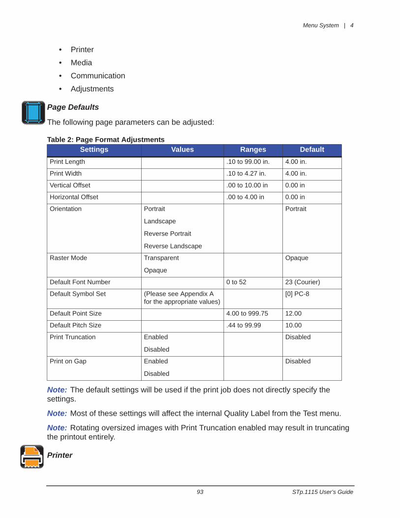
Page Defaults
The following page parameters can be adjusted:
Table 2: Page Format Adjustments
Note: The default settings will be used if the print job does not directly specify the settings.
Note: Most of these settings will affect the internal Quality Label from the Test menu.
Note: Rotating oversized images with Print Truncation enabled may result in truncating the printout entirely.
Printer
Settings Values Ranges DefaultPrint Length .10 to 99.00 in. 4.00 in.
Print Width .10 to 4.27 in. 4.00 in.
Vertical Offset .00 to 10.00 in 0.00 in
Horizontal Offset .00 to 4.00 in 0.00 in
Orientation Portrait
Landscape
Reverse Portrait
Reverse Landscape
Portrait
Raster Mode Transparent
Opaque
Opaque
Default Font Number 0 to 52 23 (Courier)
Default Symbol Set (Please see Appendix A for the appropriate values)
[0] PC-8
Default Point Size 4.00 to 999.75 12.00
Default Pitch Size .44 to 99.99 10.00
Print Truncation Enabled
Disabled
Disabled
Print on Gap Enabled
Disabled
Disabled
4 | Menu System
STp.1115 User’s Guide 94
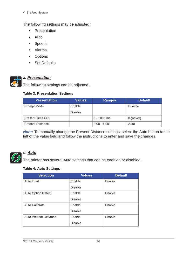
The following settings may be adjusted:
• Presentation
• Auto
• Speeds
• Alarms
• Options
• Set Defaults
a. Presentation
The following settings can be adjusted.
Table 3: Presentation Settings
Note: To manually change the Present Distance settings, select the Auto button to the left of the value field and follow the instructions to enter and save the changes.
b. Auto
The printer has several Auto settings that can be enabled or disabled.
Table 4: Auto Settings
Presentation Values Ranges DefaultPrompt Mode Enable
Disable
Disable
Present Time Out 0 - 1000 ms 0 (never)
Present Distance 0.00 - 4.00 Auto
Selection Values DefaultAuto Load Enable
Disable
Enable
Auto Option Detect Enable
Disable
Enable
Auto Calibrate Enable
Disable
Enable
Auto Present Distance Enable
Disable
Enable
Menu System | 4
95 STp.1115 User’s Guide
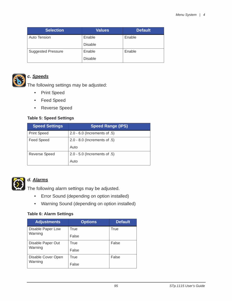
c. Speeds
The following settings may be adjusted:
• Print Speed
• Feed Speed
• Reverse Speed
Table 5: Speed Settings
d. Alarms
The following alarm settings may be adjusted.
• Error Sound (depending on option installed)
• Warning Sound (depending on option installed)
Table 6: Alarm Settings
Auto Tension Enable
Disable
Enable
Suggested Pressure Enable
Disable
Enable
Speed Settings Speed Range (IPS)Print Speed 2.0 - 6.0 (Increments of .5)
Feed Speed 2.0 - 8.0 (Increments of .5)
Auto
Reverse Speed 2.0 - 5.0 (Increments of .5)
Auto
Adjustments Options DefaultDisable Paper Low Warning
True
False
True
Disable Paper Out Warning
True
False
False
Disable Cover Open Warning
True
False
False
Selection Values Default
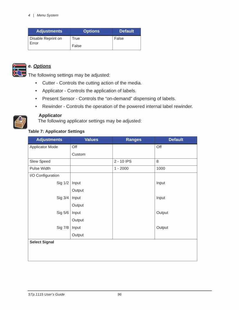
4 | Menu System
STp.1115 User’s Guide 96
e. Options
The following settings may be adjusted:
• Cutter - Controls the cutting action of the media.
• Applicator - Controls the application of labels.
• Present Sensor - Controls the “on-demand” dispensing of labels.
• Rewinder - Controls the operation of the powered internal label rewinder.
Applicator The following applicator settings may be adjusted:
Table 7: Applicator Settings
Disable Reprint on Error
True
False
False
Adjustments Values Ranges DefaultApplicator Mode Off
Custom
Off
Slew Speed 2 - 10 IPS 8
Pulse Width 1 - 2000 1000
I/O Configuration
Sig 1/2
Sig 3/4
Sig 5/6
Sig 7/8
Input
Output
Input
Output
Input
Output
Input
Output
Input
Input
Output
Output
Select Signal
Adjustments Options Default
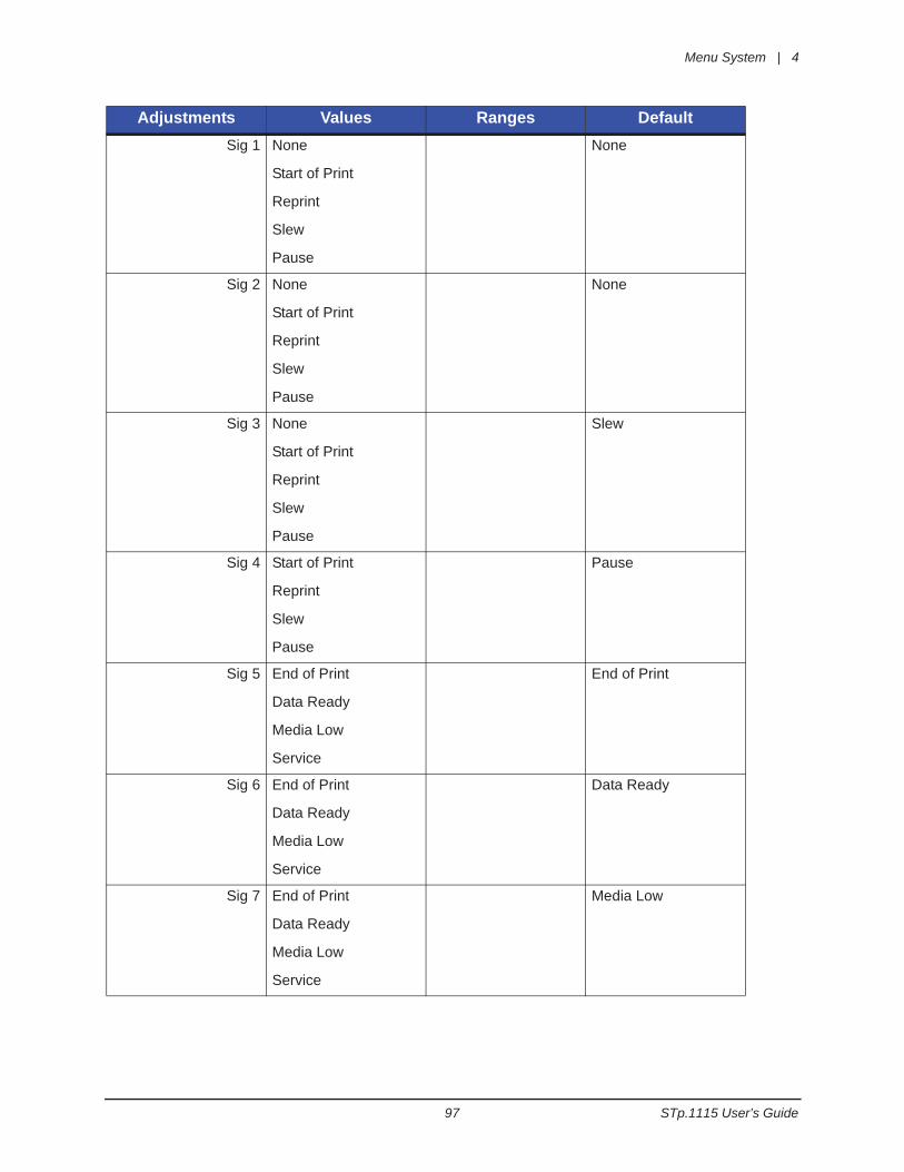
Menu System | 4
97 STp.1115 User’s Guide
Sig 1 None
Start of Print
Reprint
Slew
Pause
None
Sig 2 None
Start of Print
Reprint
Slew
Pause
None
Sig 3 None
Start of Print
Reprint
Slew
Pause
Slew
Sig 4 Start of Print
Reprint
Slew
Pause
Pause
Sig 5 End of Print
Data Ready
Media Low
Service
End of Print
Sig 6 End of Print
Data Ready
Media Low
Service
Data Ready
Sig 7 End of Print
Data Ready
Media Low
Service
Media Low
Adjustments Values Ranges Default
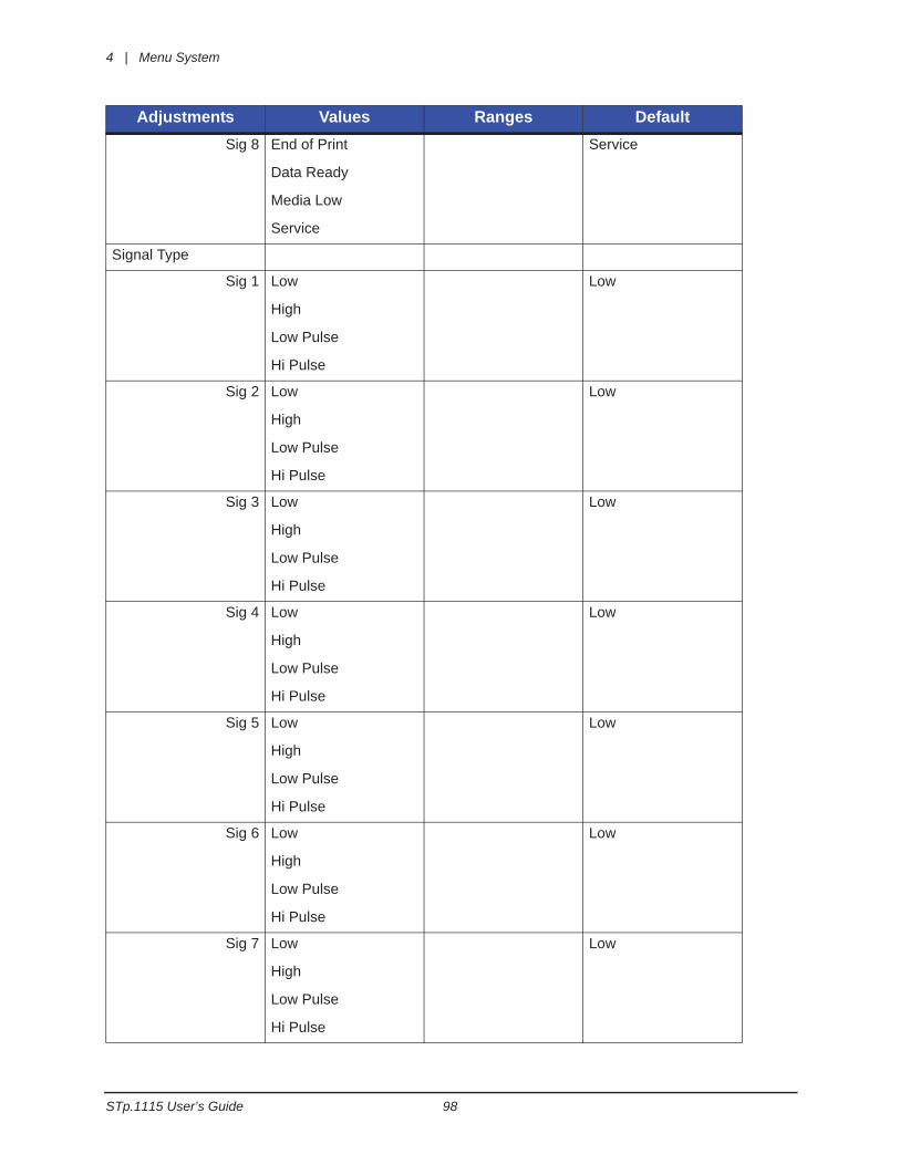
4 | Menu System
STp.1115 User’s Guide 98
Sig 8 End of Print
Data Ready
Media Low
Service
Service
Signal Type
Sig 1 Low
High
Low Pulse
Hi Pulse
Low
Sig 2 Low
High
Low Pulse
Hi Pulse
Low
Sig 3 Low
High
Low Pulse
Hi Pulse
Low
Sig 4 Low
High
Low Pulse
Hi Pulse
Low
Sig 5 Low
High
Low Pulse
Hi Pulse
Low
Sig 6 Low
High
Low Pulse
Hi Pulse
Low
Sig 7 Low
High
Low Pulse
Hi Pulse
Low
Adjustments Values Ranges Default
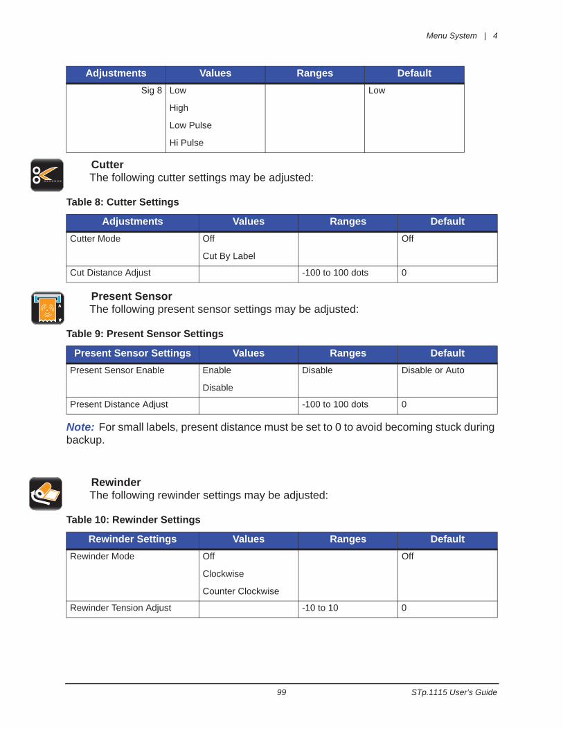
Menu System | 4
99 STp.1115 User’s Guide
CutterThe following cutter settings may be adjusted:
Table 8: Cutter Settings
Present SensorThe following present sensor settings may be adjusted:
Table 9: Present Sensor Settings
Note: For small labels, present distance must be set to 0 to avoid becoming stuck during backup.
RewinderThe following rewinder settings may be adjusted:
Table 10: Rewinder Settings
Sig 8 Low
High
Low Pulse
Hi Pulse
Low
Adjustments Values Ranges DefaultCutter Mode Off
Cut By Label
Off
Cut Distance Adjust -100 to 100 dots 0
Present Sensor Settings Values Ranges DefaultPresent Sensor Enable Enable
Disable
Disable Disable or Auto
Present Distance Adjust -100 to 100 dots 0
Rewinder Settings Values Ranges DefaultRewinder Mode Off
Clockwise
Counter Clockwise
Off
Rewinder Tension Adjust -10 to 10 0
Adjustments Values Ranges Default
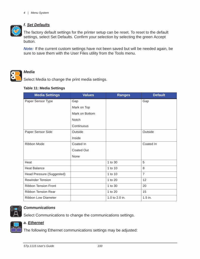
4 | Menu System
STp.1115 User’s Guide 100
f. Set Defaults
The factory default settings for the printer setup can be reset. To reset to the default settings, select Set Defaults. Confirm your selection by selecting the green Accept button.
Note: If the current custom settings have not been saved but will be needed again, be sure to save them with the User Files utility from the Tools menu.
Media
Select Media to change the print media settings.
Table 11: Media Settings
Communications
Select Communications to change the communications settings.
a. Ethernet
The following Ethernet communications settings may be adjusted:
Media Settings Values Ranges DefaultPaper Sensor Type Gap
Mark on Top
Mark on Bottom
Notch
Continuous
Gap
Paper Sensor Side Outside
Inside
Outside
Ribbon Mode Coated In
Coated Out
None
Coated In
Heat 1 to 30 5
Heat Balance 1 to 10 8
Head Pressure (Suggested) 1 to 10 7
Rewinder Tension 1 to 20 12
Ribbon Tension Front 1 to 30 20
Ribbon Tension Rear 1 to 20 15
Ribbon Low Diameter 1.0 to 2.0 in. 1.5 in.
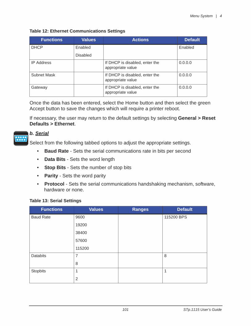
Menu System | 4
101 STp.1115 User’s Guide
Table 12: Ethernet Communications Settings
Once the data has been entered, select the Home button and then select the green Accept button to save the changes which will require a printer reboot.
If necessary, the user may return to the default settings by selecting General > Reset Defaults > Ethernet.
b. Serial
Select from the following tabbed options to adjust the appropriate settings.
• Baud Rate - Sets the serial communications rate in bits per second
• Data Bits - Sets the word length
• Stop Bits - Sets the number of stop bits
• Parity - Sets the word parity
• Protocol - Sets the serial communications handshaking mechanism, software, hardware or none.
Table 13: Serial Settings
Functions Values Actions DefaultDHCP Enabled
Disabled
Enabled
IP Address If DHCP is disabled, enter the appropriate value
0.0.0.0
Subnet Mask If DHCP is disabled, enter the appropriate value
0.0.0.0
Gateway If DHCP is disabled, enter the appropriate value
0.0.0.0
Functions Values Ranges DefaultBaud Rate 9600
19200
38400
57600
115200
115200 BPS
Databits 7
8
8
Stopbits 1
2
1
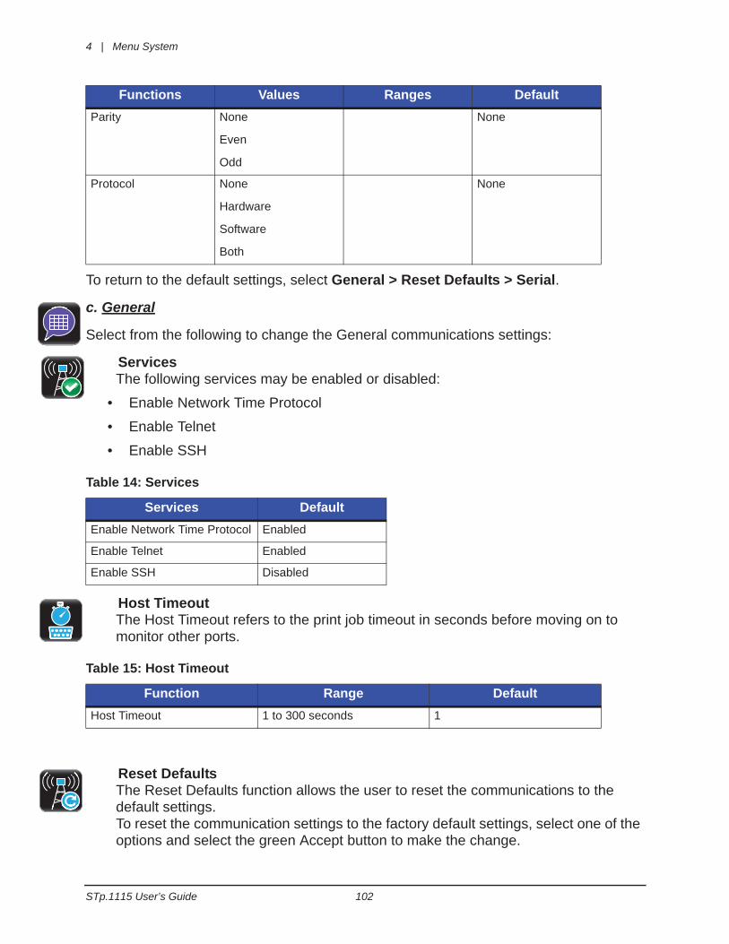
4 | Menu System
STp.1115 User’s Guide 102
To return to the default settings, select General > Reset Defaults > Serial.
c. General
Select from the following to change the General communications settings:
ServicesThe following services may be enabled or disabled:
• Enable Network Time Protocol
• Enable Telnet
• Enable SSH
Table 14: Services
Host TimeoutThe Host Timeout refers to the print job timeout in seconds before moving on to monitor other ports.
Table 15: Host Timeout
Reset DefaultsThe Reset Defaults function allows the user to reset the communications to the default settings.To reset the communication settings to the factory default settings, select one of the options and select the green Accept button to make the change.
Parity None
Even
Odd
None
Protocol None
Hardware
Software
Both
None
Services DefaultEnable Network Time Protocol Enabled
Enable Telnet Enabled
Enable SSH Disabled
Function Range DefaultHost Timeout 1 to 300 seconds 1
Functions Values Ranges Default
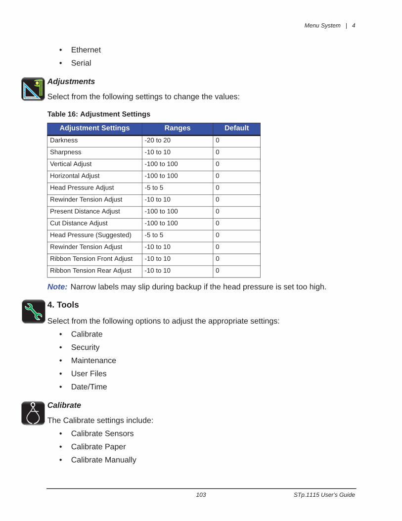
Menu System | 4
103 STp.1115 User’s Guide
• Ethernet
• Serial
Adjustments
Select from the following settings to change the values:
Table 16: Adjustment Settings
Note: Narrow labels may slip during backup if the head pressure is set too high.
4. Tools
Select from the following options to adjust the appropriate settings:
• Calibrate
• Security
• Maintenance
• User Files
• Date/Time
Calibrate
The Calibrate settings include:
• Calibrate Sensors
• Calibrate Paper
• Calibrate Manually
Adjustment Settings Ranges DefaultDarkness -20 to 20 0
Sharpness -10 to 10 0
Vertical Adjust -100 to 100 0
Horizontal Adjust -100 to 100 0
Head Pressure Adjust -5 to 5 0
Rewinder Tension Adjust -10 to 10 0
Present Distance Adjust -100 to 100 0
Cut Distance Adjust -100 to 100 0
Head Pressure (Suggested) -5 to 5 0
Rewinder Tension Adjust -10 to 10 0
Ribbon Tension Front Adjust -10 to 10 0
Ribbon Tension Rear Adjust -10 to 10 0
4 | Menu System
STp.1115 User’s Guide 104
• Calibrate Display
a. Calibrate Sensors
Select Calibrate Sensors to automatically calibrate the printer without print media. Calibration includes changes to the following settings:
• Head Pressure (Suggested)
• Auto Load Sensor
• Top-of-Form Sensor
Note: The print media must be removed and the printhead mechanism must be unlatched for the Calibrate Sensors to properly calibrate the printer.
b. Calibrate Paper
When selecting Calibrate Paper, the paper is scanned to determine the top-of-form media and top-of-form gap settings.
Upon selection, the printer will move the paper forward and backward over the gap or mark.
Note: Print media must be properly installed in the printer for the Calibrate Paper function.
Note: Manually selecting Calibrate Paper is not necessary if Auto Calibration is enabled. However, it may help in calibrating more difficult media.
c. Calibrate Manually
Intended for advanced users, the calibrate manually section allows the user to manually adjust the top-of-form sensor for specialized media.The TOF ADC Reading field displays the current top-of-form sensor reading for the currently selected paper type and sensor side.
The values for gain, paper threshold and gap/mark threshold are shown for the currently selected paper type and sensor side as well. These values are typically set when auto calibration is performed in the Calibrate Paper utility.
The capture feature allows the user to lift the printhead, and using the LED as a guide place the paper under the sensor and capture the value. Then, moving the gap (media backing) or mark under the sensor, the value can be captured.
When saving changes to a threshold, auto calibration is disabled to prevent over-writing the new values when auto-loading. Performing Calibrate Paper will overwrite the threshold values.
Select Calibrate Manually to change the following settings:
• Top-of-Form Gain
• Paper Threshold
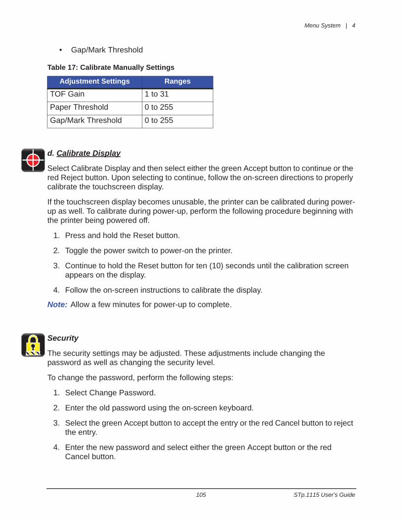
Menu System | 4
105 STp.1115 User’s Guide
• Gap/Mark Threshold
Table 17: Calibrate Manually Settings
d. Calibrate Display
Select Calibrate Display and then select either the green Accept button to continue or the red Reject button. Upon selecting to continue, follow the on-screen directions to properly calibrate the touchscreen display.
If the touchscreen display becomes unusable, the printer can be calibrated during power-up as well. To calibrate during power-up, perform the following procedure beginning with the printer being powered off.
1. Press and hold the Reset button.
2. Toggle the power switch to power-on the printer.
3. Continue to hold the Reset button for ten (10) seconds until the calibration screen appears on the display.
4. Follow the on-screen instructions to calibrate the display.
Note: Allow a few minutes for power-up to complete.
Security
The security settings may be adjusted. These adjustments include changing the password as well as changing the security level.
To change the password, perform the following steps:
1. Select Change Password.
2. Enter the old password using the on-screen keyboard.
3. Select the green Accept button to accept the entry or the red Cancel button to reject the entry.
4. Enter the new password and select either the green Accept button or the red Cancel button.
Adjustment Settings Ranges
TOF Gain 1 to 31
Paper Threshold 0 to 255
Gap/Mark Threshold 0 to 255
4 | Menu System
STp.1115 User’s Guide 106
5. Re-enter the new password and select either the green Accept button or the red cancel button.
To change the security level, choose from the following options:
Table 18: Security Settings
Security Descriptions• Secure - When the “Secure” option is selected, changes to the advanced settings
and user tools will require a password.
• Secure All - When the “Secure All” option is selected, changes to any settings will require a password.
Note: The factory default password is the number “0.”
Note: By default, security should be disabled.
Remove Security
To remove security, select the lock icon to the right of the Change Password utility. Type your password and then select the green Accept button. To confirm, select the green Accept button.
Maintenance
To adjust the following Maintenance settings, select the Maintenance button. The maintenance settings include:
• Cleaning
• Upgrade
• Odometers
a. Cleaning
Cleaning should be routinely performed. The maintenance alarm is set by the user in thousands of inches.
Enter the desired maintenance reminder interval. Once a fault appears directing the user to clean the printhead, insert a factory approved cleaning card under the printhead and select Clean Now.
The Elapsed field displays the number of inches, in thousands, since the last cleaning.
Functions OptionsSecurity Level Off
Secure
Secure All
Menu System | 4
107 STp.1115 User’s Guide
Table 19: Maintenance Settings
b. Upgrade
The Upgrade function allows the user to upgrade the printer software. Insert a mass storage device into the USB host with the appropriate file to be uploaded and then select Upgrade.
Do not turn off the printer during the process. Once the printer has been updated, it willreboot. Once the printer is online, be sure to power-cycle the printer once more by turningit off and then back on.
Note: Be sure to save all user files, labels and setups to a mass storage device connected to the USB host prior to updating your printer. Files that are not saved may be lost during the upgrade process.
c. Odometers
The following Odometer readings are managed:
• Printer
• User
Note: The printhead odometer will not display in this area.
To reset the user odometer, select the Reset User button.
User Files
The User Files utility allows the user to access files that are saved internally or saved to a mass storage device.
a. Labels
Labels can be saved either internally or to a mass storage device. These labels can also be printed from this utility. Labels stored on a mass storage device must be placed in a directory called user_labels.
PrintThe user can print label files that have been saved internally or saved to a mass storage device attached to the USB host.
1. Select Print.
2. Using the scroll arrows, highlight the file to be printed.
Maintenance Settings Ranges Actions DefaultMaintenance 0k to 1000k in. 0 (never)
Clean Now Select Clean Now
4 | Menu System
STp.1115 User’s Guide 108
Note: The first tab displayed in the interface reveals the files that have been saved internally. Tab 2 displays the available files from the attached mass storage device.
3. Select the green Accept button.
4. Select the printer icon in the taskbar.
OrganizeUser labels may be copied from a mass storage device to the internal memory or from the internal memory to a mass storage device. They may also be deleted or renamed from this utility.
a. Copy
1. Select Organize.
2. Using the scroll arrows, highlight the appropriate file.
3. Select the green Accept button to continue.
4. Select Copy.
5. Select the green accept button to copy the files between internal storage and the USB mass storage device.
b. Delete
1. Select Organize.
2. Using the scroll arrows, highlight the appropriate file.
3. Select the green Accept button to continue.
4. Select Delete.
c. Rename
1. Select Organize.
2. Using the scroll arrows, highlight the appropriate file.
3. Select the green Accept button to continue.
4. Select Rename.
5. Confirm your selection by selecting the green Accept button.
6. Using the alpha-numeric keypad, enter a new name for the selected file.
7. Select the green Accept button to continue.
b. Media
The Media utility allows the user to copy, delete and rename media configuration files. It also provides access to setup files stored internally or on a mass storage device
R N
Menu System | 4
109 STp.1115 User’s Guide
connected to the USB host. The user can also save the current media configuration setup. Media configuration files that are stored on a mass storage device must be placed in a directory called user_media.
The settings include the following:
• Media ID
• Ribbon ID
• Paper Sensor Side
• Paper Sensor Type
• Ribbon Mode
• Heat
• Heat Balance
• Head Pressure
• Rewinder Tension
• Ribbon Tension Front
• Ribbon Tension Rear
• Print Speed
OrganizeTo copy, delete or rename a file to or from a mass storage device connected to the USB host, perform the following steps:
a. Copy
1. Select Organize.
2. Using the scroll arrows, highlight the appropriate media configuration file.
3. Select the green Accept button to continue.
4. Select Copy.
5. Select the green Accept button to confirm.
b. Delete
1. Select Organize.
2. Using the scroll arrows, highlight the appropriate media configuration file.
3. Select the green Accept button to continue.
4. Select Delete.
5. Select the green Accept button to confirm.

4 | Menu System
STp.1115 User’s Guide 110
c. Rename
1. Select Organize.
2. Using the scroll arrows, highlight the appropriate media configuration file.
3. Select the green Accept button to continue.
4. Select Rename.
5. Using the alpha-numeric keypad, enter a new name for the selected file.
6. Select the green Accept button to confirm.
Load SetupThe Load Setup utility allows the user to change the media configuration settings to a setup that was previously saved internally or to a mass storage device.
1. Select Load Setup.
2. Using the scroll arrows, highlight the appropriate media setup file.
3. Select the green Accept button.
4. Select the green Accept button to confirm.
Save SetupThe Save Setup utility allows the user to save the current media configuration settings internally.
1. Select Save Setup.
2. Using the alpha-numeric keypad, type a name for the current media configuration.
3. Select the green Accept button.
4. Select the green Accept button to confirm.
c. Setups
The User Setup utility allows for the user to copy, delete and rename printer settings. The user can also save the current setup and load a saved setup. User setup files stored on a mass storage device must be placed in a directory called user_configs.
These settings include the ones listed in the Setting Report from the Info menu and exclude adjustments and calibration settings.
OrganizeTo copy, delete or rename a printer configuration setup file to or from a mass storage device connected to the USB host, perform the following steps:
a. Copy
1. Select Organize.
R N

Menu System | 4
111 STp.1115 User’s Guide
2. Using the scroll arrows, highlight the appropriate user setup file.
3. Select the green Accept button to continue.
4. Select Copy.
5. Select the green Accept button to confirm.
b. Delete
1. Select Organize.
2. Using the scroll arrows, highlight the appropriate user setup file.
3. Select the green Accept button to continue.
4. Select Delete.
5. Select the green Accept button to confirm.
c. Rename
1. Select Organize.
2. Using the scroll arrows, highlight the appropriate user setup file.
3. Select the green Accept button to continue.
4. Select Rename.
5. To confirm, select the green Accept button.
6. Using the alpha-numeric keypad, type a name in the entry field.
7. Select the green Accept button to confirm.
Load SetupThe Load Setup utility allows the printer settings to be changed to a previously saved setup.
1. Select Load Setup.
2. Using the scroll arrows, highlight the appropriate user setup file.
3. Select the green Accept button to continue.
4. Select the green Accept button to confirm.
Save SetupThe Save Setup utility allows the user to save the current printer settings internally.
1. Select Save Setup.
2. Using the alpha-numeric keypad, enter a name for the setup to be saved.
R N

4 | Menu System
STp.1115 User’s Guide 112
3. Select the green Accept button.
4. Select the green Accept button to confirm.
Date/Time
To set the date and time, select the Date/Time button from the Tools menu.
If the message “Network Time Protocol Enabled!” appears, select the green Accept button.
To adjust the settings, select the following buttons and input the appropriate information.
• Month
• Day
• Year
• Hour
• Minutes
• AM/PM
Note: Upon exit, the user can enable the displaying of the date and time on the main screen.
5. Language
Select from the localization settings and display units.
Language Files• English
• Spanish*
• French*
• Italian*
• German**Future Features
Display Units• Imperial
• Metric
Once the unit has been chosen, select the green Accept button to continue and then select the next green Accept button to confirm.
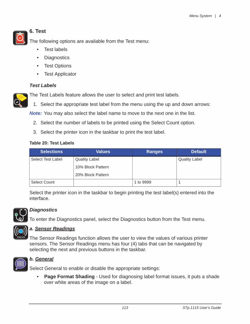
Menu System | 4
113 STp.1115 User’s Guide
6. Test
The following options are available from the Test menu:
• Test labels
• Diagnostics
• Test Options
• Test Applicator
Test Labels
The Test Labels feature allows the user to select and print test labels.
1. Select the appropriate test label from the menu using the up and down arrows:
Note: You may also select the label name to move to the next one in the list.
2. Select the number of labels to be printed using the Select Count option.
3. Select the printer icon in the taskbar to print the test label.
Table 20: Test Labels
Select the printer icon in the taskbar to begin printing the test label(s) entered into the interface.
Diagnostics
To enter the Diagnostics panel, select the Diagnostics button from the Test menu.
a. Sensor Readings
The Sensor Readings function allows the user to view the values of various printer sensors. The Sensor Readings menu has four (4) tabs that can be navigated by selecting the next and previous buttons in the taskbar.
b. General
Select General to enable or disable the appropriate settings:
• Page Format Shading - Used for diagnosing label format issues, it puts a shade over white areas of the image on a label.
Selections Values Ranges DefaultSelect Test Label Quality Label
10% Block Pattern
20% Block Pattern
Quality Label
Select Count 1 to 9999 1
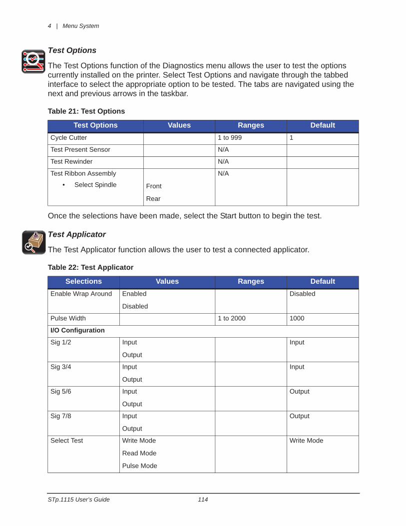
4 | Menu System
STp.1115 User’s Guide 114
Test Options
The Test Options function of the Diagnostics menu allows the user to test the options currently installed on the printer. Select Test Options and navigate through the tabbed interface to select the appropriate option to be tested. The tabs are navigated using the next and previous arrows in the taskbar.
Table 21: Test Options
Once the selections have been made, select the Start button to begin the test.
Test Applicator
The Test Applicator function allows the user to test a connected applicator.
Table 22: Test Applicator
Test Options Values Ranges DefaultCycle Cutter 1 to 999 1
Test Present Sensor N/A
Test Rewinder N/A
Test Ribbon Assembly
• Select Spindle Front
Rear
N/A
Selections Values Ranges DefaultEnable Wrap Around Enabled
Disabled
Disabled
Pulse Width 1 to 2000 1000
I/O Configuration
Sig 1/2 Input
Output
Input
Sig 3/4 Input
Output
Input
Sig 5/6 Input
Output
Output
Sig 7/8 Input
Output
Output
Select Test Write Mode
Read Mode
Pulse Mode
Write Mode
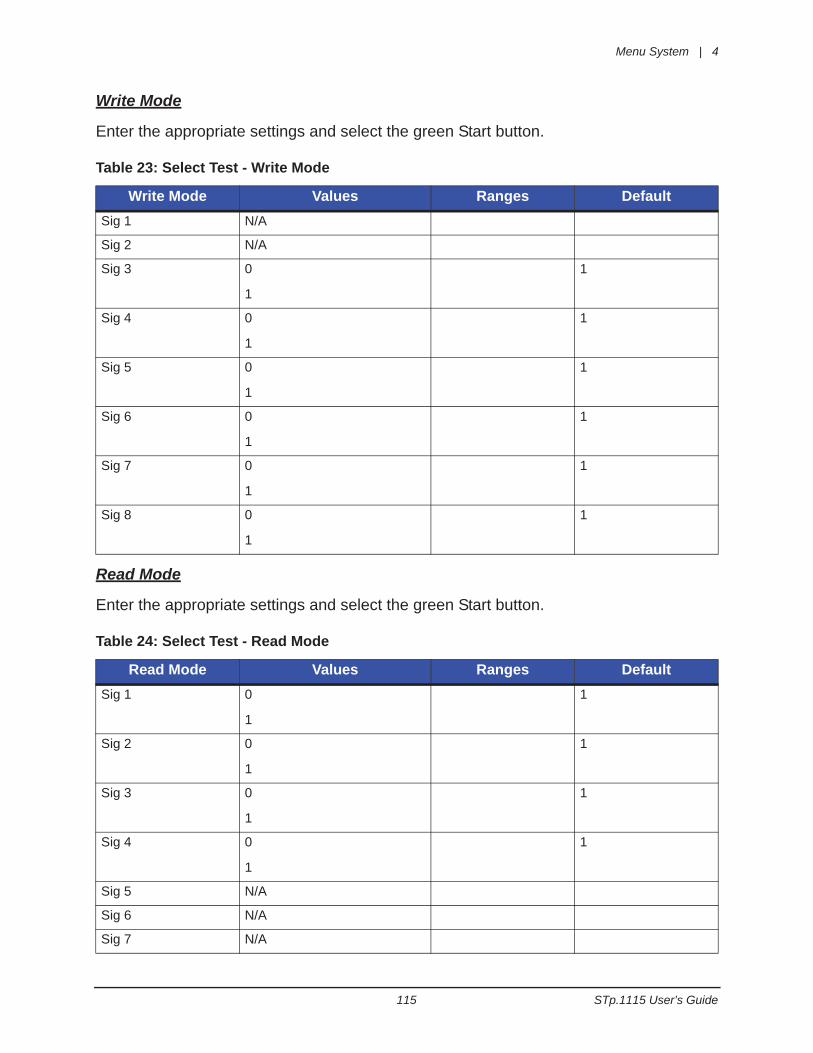
Menu System | 4
115 STp.1115 User’s Guide
Write Mode
Enter the appropriate settings and select the green Start button.
Table 23: Select Test - Write Mode
Read Mode
Enter the appropriate settings and select the green Start button.
Table 24: Select Test - Read Mode
Write Mode Values Ranges DefaultSig 1 N/A
Sig 2 N/A
Sig 3 0
1
1
Sig 4 0
1
1
Sig 5 0
1
1
Sig 6 0
1
1
Sig 7 0
1
1
Sig 8 0
1
1
Read Mode Values Ranges DefaultSig 1 0
1
1
Sig 2 0
1
1
Sig 3 0
1
1
Sig 4 0
1
1
Sig 5 N/A
Sig 6 N/A
Sig 7 N/A
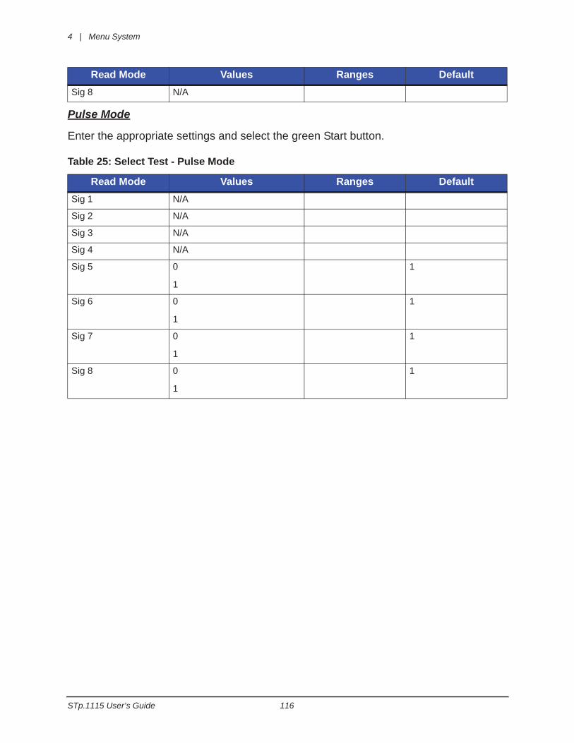
4 | Menu System
STp.1115 User’s Guide 116
Pulse Mode
Enter the appropriate settings and select the green Start button.
Table 25: Select Test - Pulse Mode
Sig 8 N/A
Read Mode Values Ranges DefaultSig 1 N/A
Sig 2 N/A
Sig 3 N/A
Sig 4 N/A
Sig 5 0
1
1
Sig 6 0
1
1
Sig 7 0
1
1
Sig 8 0
1
1
Read Mode Values Ranges Default
117 STp.1115 User’s Guide
5 Cleaning and Maintenance
OverviewTo maintain good print quality and increase printhead life, proper cleaning should be routinely performed using factory-approved cleaning supplies.
Caution: A contaminated printhead can cause premature printhead failure.
Caution: Failure to clean the printhead as detailed in this manual could void theprinthead manufacturer’s warranty.
IntervalsFor direct thermal printing, the printhead should be cleaned whenever a roll of labels is replaced or every 650 inches printed. For users printing via thermal transfer, the printhead should be cleaned every time a roll of ribbon is replaced.
Supplies
Caution: Cleaning should only be performed using factory-approved and authorizedcleaning supplies. Any use of non-authorized cleaning supplies can void theprinthead and platen roller warranties.
• Cleaning Pens
• Cleaning Cards
• Can of Compressed Air
• Clean, lint-free cloth
• Isopropyl Alcohol
Cleaning Pens - Reorder Information• Standard Thermal Printer Cleaning Pen - P/N SP105965-001• Premium Dual Action Cleaning Pen - P/N SP105965-002
Cleaning Cards - Reorder Information• Standard Thermal Printer Cleaning Card - P/N SP105966-001• Deluxe Thermal Printer Cleaning Card Series 112 - P/N SP105966-002• Premium Thermal Printer Cleaning Card Series 212 - P/N SP105966-003
5 | Cleaning and Maintenance
STp.1115 User’s Guide 118
Cleaning the Automatic Loading SensorThe automatic loading sensor should be cleaned whenever necessary.
1. Remove the labels.
2. With a can of compressed air, spray the sensor to remove dust and debris.
3. Repeat as necessary.
Cleaning the Top-of-Form SensorThe Top of Form sensor should be cleaned whenever necessary.
1. Remove the media and ribbon.
2. With a can of compressed air, spray both (2) sensors to remove dust and debris.
3. Repeat as necessary.
Cleaning the Label Low SensorThe Label Low Sensor should be cleaned whenever necessary.
1. Remove the media and ribbon.
2. Wipe the sensor with the clean, lint-free cloth.
3. Repeat as necessary.
Cleaning the Printhead For optimum performance, the printhead should be routinely cleaned with factory-approved cleaning supplies. When using the cleaning pen, follow the instructions located on the packaging.
Cleaning Cards
Cleaning cards are effective at removing many common adhesives and contaminants from printheads.
1. Remove the media and ribbon.
2. Insert the cleaning card under the printhead.
3. Select Menu / Tools / Maintenance / Cleaning and then select Clean Now.
4. Slide the cleaning card in and out to scrub the printhead.
5. Repeat as necessary.

Cleaning and Maintenance | 5
119 STp.1115 User’s Guide
Cleaning the CutterThe cutter should be routinely cleaned to prevent jams.
1. Release the cutter mechanism from its magnetic hold.
2. Using a can of compressed air, gently blow out the debris from the cutter area.
Warning: To prevent injury, the cutter should never be disassembled for any reason.

5 | Cleaning and Maintenance
STp.1115 User’s Guide 120
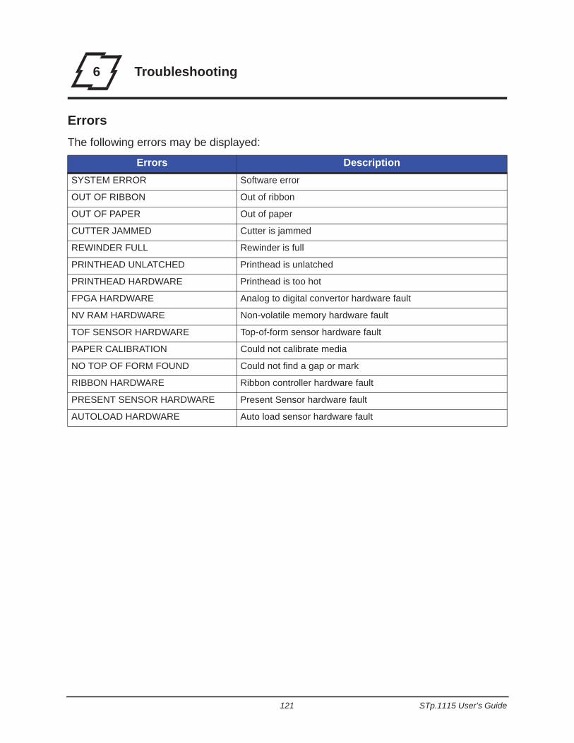
121 STp.1115 User’s Guide
6 Troubleshooting
ErrorsThe following errors may be displayed:
Errors DescriptionSYSTEM ERROR Software error
OUT OF RIBBON Out of ribbon
OUT OF PAPER Out of paper
CUTTER JAMMED Cutter is jammed
REWINDER FULL Rewinder is full
PRINTHEAD UNLATCHED Printhead is unlatched
PRINTHEAD HARDWARE Printhead is too hot
FPGA HARDWARE Analog to digital convertor hardware fault
NV RAM HARDWARE Non-volatile memory hardware fault
TOF SENSOR HARDWARE Top-of-form sensor hardware fault
PAPER CALIBRATION Could not calibrate media
NO TOP OF FORM FOUND Could not find a gap or mark
RIBBON HARDWARE Ribbon controller hardware fault
PRESENT SENSOR HARDWARE Present Sensor hardware fault
AUTOLOAD HARDWARE Auto load sensor hardware fault
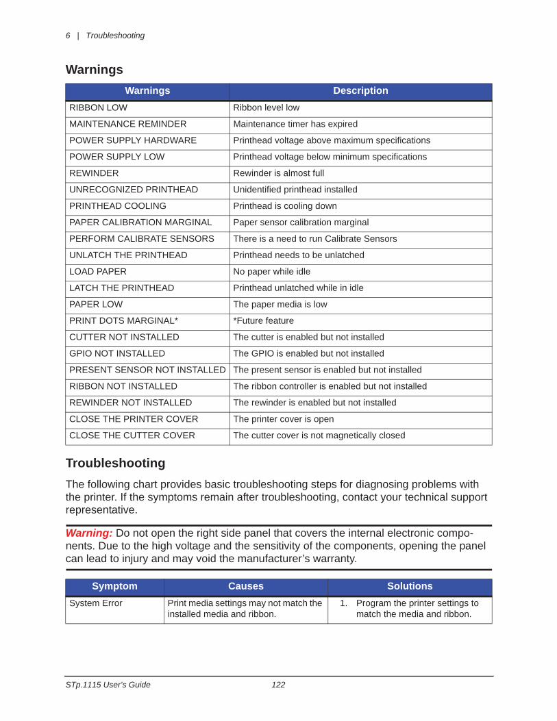
6 | Troubleshooting
STp.1115 User’s Guide 122
Warnings
TroubleshootingThe following chart provides basic troubleshooting steps for diagnosing problems with the printer. If the symptoms remain after troubleshooting, contact your technical support representative.
Warning: Do not open the right side panel that covers the internal electronic compo-nents. Due to the high voltage and the sensitivity of the components, opening the panel can lead to injury and may void the manufacturer’s warranty.
Warnings DescriptionRIBBON LOW Ribbon level low
MAINTENANCE REMINDER Maintenance timer has expired
POWER SUPPLY HARDWARE Printhead voltage above maximum specifications
POWER SUPPLY LOW Printhead voltage below minimum specifications
REWINDER Rewinder is almost full
UNRECOGNIZED PRINTHEAD Unidentified printhead installed
PRINTHEAD COOLING Printhead is cooling down
PAPER CALIBRATION MARGINAL Paper sensor calibration marginal
PERFORM CALIBRATE SENSORS There is a need to run Calibrate Sensors
UNLATCH THE PRINTHEAD Printhead needs to be unlatched
LOAD PAPER No paper while idle
LATCH THE PRINTHEAD Printhead unlatched while in idle
PAPER LOW The paper media is low
PRINT DOTS MARGINAL* *Future feature
CUTTER NOT INSTALLED The cutter is enabled but not installed
GPIO NOT INSTALLED The GPIO is enabled but not installed
PRESENT SENSOR NOT INSTALLED The present sensor is enabled but not installed
RIBBON NOT INSTALLED The ribbon controller is enabled but not installed
REWINDER NOT INSTALLED The rewinder is enabled but not installed
CLOSE THE PRINTER COVER The printer cover is open
CLOSE THE CUTTER COVER The cutter cover is not magnetically closed
Symptom Causes SolutionsSystem Error Print media settings may not match the
installed media and ribbon.1. Program the printer settings to
match the media and ribbon.
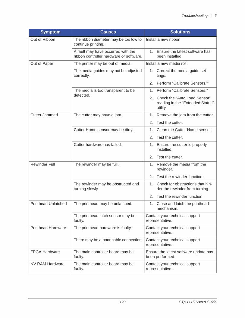
Troubleshooting | 6
123 STp.1115 User’s Guide
Out of Ribbon The ribbon diameter may be too low to continue printing.
Install a new ribbon
A fault may have occurred with the ribbon controller hardware or software.
1. Ensure the latest software has been installed.
Out of Paper The printer may be out of media. Install a new media roll.
The media guides may not be adjusted correctly.
1. Correct the media guide set-tings.
2. Perform “Calibrate Sensors.””
The media is too transparent to be detected.
1. Perform “Calibrate Sensors.”
2. Check the “Auto Load Sensor” reading in the “Extended Status” utility.
Cutter Jammed The cutter may have a jam. 1. Remove the jam from the cutter.
2. Test the cutter.
Cutter Home sensor may be dirty. 1. Clean the Cutter Home sensor.
2. Test the cutter.
Cutter hardware has failed. 1. Ensure the cutter is properly installed.
2. Test the cutter.
Rewinder Full The rewinder may be full. 1. Remove the media from the rewinder.
2. Test the rewinder function.
The rewinder may be obstructed and turning slowly.
1. Check for obstructions that hin-der the rewinder from turning.
2. Test the rewinder function.
Printhead Unlatched The printhead may be unlatched. 1. Close and latch the printhead mechanism.
The printhead latch sensor may be faulty.
Contact your technical support representative.
Printhead Hardware The printhead hardware is faulty. Contact your technical support representative.
There may be a poor cable connection. Contact your technical support representative.
FPGA Hardware The main controller board may be faulty.
Ensure the latest software update has been performed.
NV RAM Hardware The main controller board may be faulty.
Contact your technical support representative.
Symptom Causes Solutions
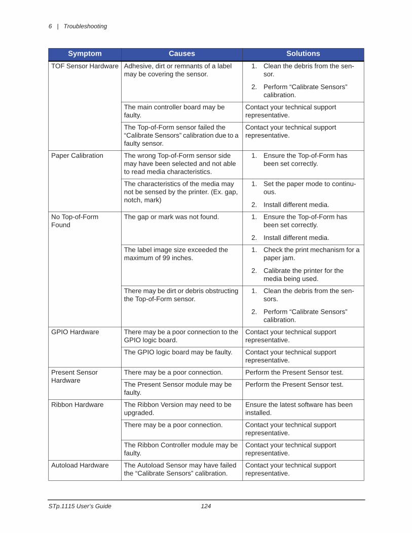
6 | Troubleshooting
STp.1115 User’s Guide 124
TOF Sensor Hardware Adhesive, dirt or remnants of a label may be covering the sensor.
1. Clean the debris from the sen-sor.
2. Perform “Calibrate Sensors” calibration.
The main controller board may be faulty.
Contact your technical support representative.
The Top-of-Form sensor failed the “Calibrate Sensors” calibration due to a faulty sensor.
Contact your technical support representative.
Paper Calibration The wrong Top-of-Form sensor side may have been selected and not able to read media characteristics.
1. Ensure the Top-of-Form has been set correctly.
The characteristics of the media may not be sensed by the printer. (Ex. gap, notch, mark)
1. Set the paper mode to continu-ous.
2. Install different media.
No Top-of-Form Found
The gap or mark was not found. 1. Ensure the Top-of-Form has been set correctly.
2. Install different media.
The label image size exceeded the maximum of 99 inches.
1. Check the print mechanism for a paper jam.
2. Calibrate the printer for the media being used.
There may be dirt or debris obstructing the Top-of-Form sensor.
1. Clean the debris from the sen-sors.
2. Perform “Calibrate Sensors” calibration.
GPIO Hardware There may be a poor connection to the GPIO logic board.
Contact your technical support representative.
The GPIO logic board may be faulty. Contact your technical support representative.
Present Sensor Hardware
There may be a poor connection. Perform the Present Sensor test.
The Present Sensor module may be faulty.
Perform the Present Sensor test.
Ribbon Hardware The Ribbon Version may need to be upgraded.
Ensure the latest software has been installed.
There may be a poor connection. Contact your technical support representative.
The Ribbon Controller module may be faulty.
Contact your technical support representative.
Autoload Hardware The Autoload Sensor may have failed the “Calibrate Sensors” calibration.
Contact your technical support representative.
Symptom Causes Solutions
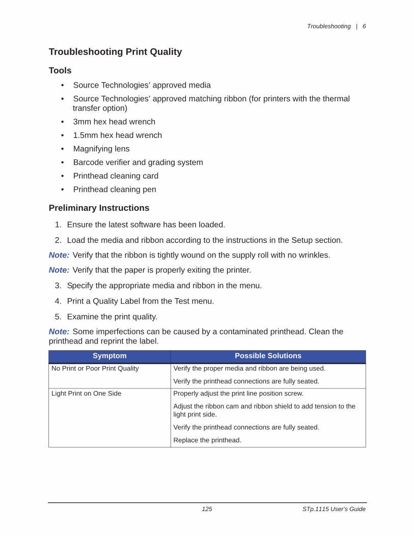
Troubleshooting | 6
125 STp.1115 User’s Guide
Troubleshooting Print Quality
Tools• Source Technologies’ approved media
• Source Technologies’ approved matching ribbon (for printers with the thermal transfer option)
• 3mm hex head wrench
• 1.5mm hex head wrench
• Magnifying lens
• Barcode verifier and grading system
• Printhead cleaning card
• Printhead cleaning pen
Preliminary Instructions
1. Ensure the latest software has been loaded.
2. Load the media and ribbon according to the instructions in the Setup section.
Note: Verify that the ribbon is tightly wound on the supply roll with no wrinkles.
Note: Verify that the paper is properly exiting the printer.
3. Specify the appropriate media and ribbon in the menu.
4. Print a Quality Label from the Test menu.
5. Examine the print quality.
Note: Some imperfections can be caused by a contaminated printhead. Clean the printhead and reprint the label.
Symptom Possible SolutionsNo Print or Poor Print Quality Verify the proper media and ribbon are being used.
Verify the printhead connections are fully seated.
Light Print on One Side Properly adjust the print line position screw.
Adjust the ribbon cam and ribbon shield to add tension to the light print side.
Verify the printhead connections are fully seated.
Replace the printhead.
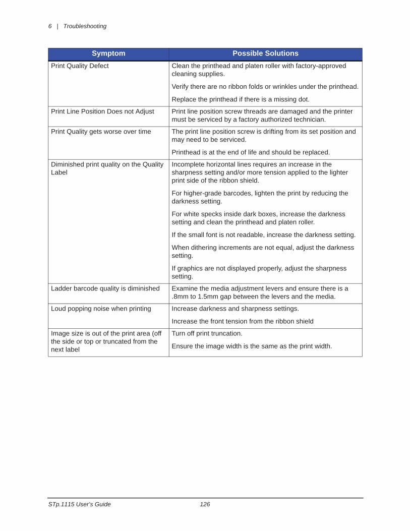
6 | Troubleshooting
STp.1115 User’s Guide 126
Print Quality Defect Clean the printhead and platen roller with factory-approved cleaning supplies.
Verify there are no ribbon folds or wrinkles under the printhead.
Replace the printhead if there is a missing dot.
Print Line Position Does not Adjust Print line position screw threads are damaged and the printer must be serviced by a factory authorized technician.
Print Quality gets worse over time The print line position screw is drifting from its set position and may need to be serviced.
Printhead is at the end of life and should be replaced.
Diminished print quality on the Quality Label
Incomplete horizontal lines requires an increase in the sharpness setting and/or more tension applied to the lighter print side of the ribbon shield.
For higher-grade barcodes, lighten the print by reducing the darkness setting.
For white specks inside dark boxes, increase the darkness setting and clean the printhead and platen roller.
If the small font is not readable, increase the darkness setting.
When dithering increments are not equal, adjust the darkness setting.
If graphics are not displayed properly, adjust the sharpness setting.
Ladder barcode quality is diminished Examine the media adjustment levers and ensure there is a .8mm to 1.5mm gap between the levers and the media.
Loud popping noise when printing Increase darkness and sharpness settings.
Increase the front tension from the ribbon shield
Image size is out of the print area (off the side or top or truncated from the next label
Turn off print truncation.
Ensure the image width is the same as the print width.
Symptom Possible Solutions
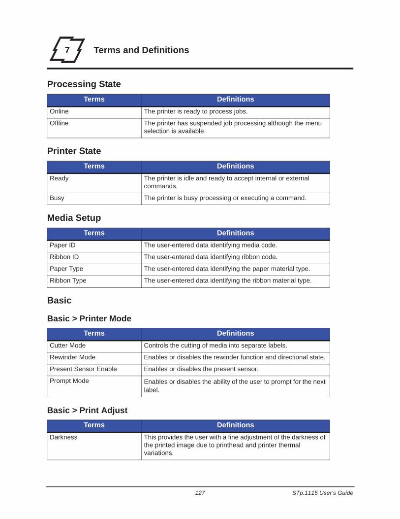
127 STp.1115 User’s Guide
7 Terms and Definitions
Processing State
Printer State
Media Setup
Basic
Basic > Printer Mode
Basic > Print Adjust
Terms DefinitionsOnline The printer is ready to process jobs.
Offline The printer has suspended job processing although the menu selection is available.
Terms DefinitionsReady The printer is idle and ready to accept internal or external
commands.
Busy The printer is busy processing or executing a command.
Terms DefinitionsPaper ID The user-entered data identifying media code.
Ribbon ID The user-entered data identifying ribbon code.
Paper Type The user-entered data identifying the paper material type.
Ribbon Type The user-entered data identifying the ribbon material type.
Terms DefinitionsCutter Mode Controls the cutting of media into separate labels.
Rewinder Mode Enables or disables the rewinder function and directional state.
Present Sensor Enable Enables or disables the present sensor.
Prompt Mode Enables or disables the ability of the user to prompt for the next label.
Terms DefinitionsDarkness This provides the user with a fine adjustment of the darkness of
the printed image due to printhead and printer thermal variations.
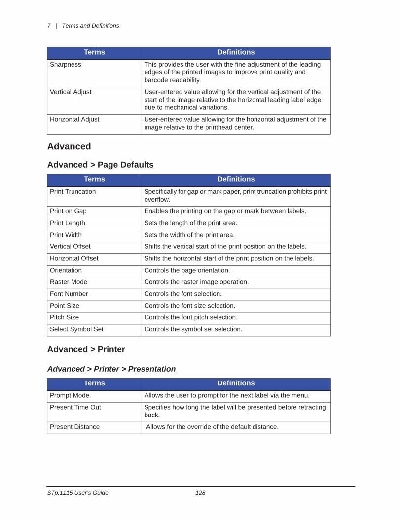
7 | Terms and Definitions
STp.1115 User’s Guide 128
Advanced
Advanced > Page Defaults
Advanced > Printer
Advanced > Printer > Presentation
Sharpness This provides the user with the fine adjustment of the leading edges of the printed images to improve print quality and barcode readability.
Vertical Adjust User-entered value allowing for the vertical adjustment of the start of the image relative to the horizontal leading label edge due to mechanical variations.
Horizontal Adjust User-entered value allowing for the horizontal adjustment of the image relative to the printhead center.
Terms DefinitionsPrint Truncation Specifically for gap or mark paper, print truncation prohibits print
overflow.
Print on Gap Enables the printing on the gap or mark between labels.
Print Length Sets the length of the print area.
Print Width Sets the width of the print area.
Vertical Offset Shifts the vertical start of the print position on the labels.
Horizontal Offset Shifts the horizontal start of the print position on the labels.
Orientation Controls the page orientation.
Raster Mode Controls the raster image operation.
Font Number Controls the font selection.
Point Size Controls the font size selection.
Pitch Size Controls the font pitch selection.
Select Symbol Set Controls the symbol set selection.
Terms DefinitionsPrompt Mode Allows the user to prompt for the next label via the menu.
Present Time Out Specifies how long the label will be presented before retracting back.
Present Distance Allows for the override of the default distance.
Terms Definitions
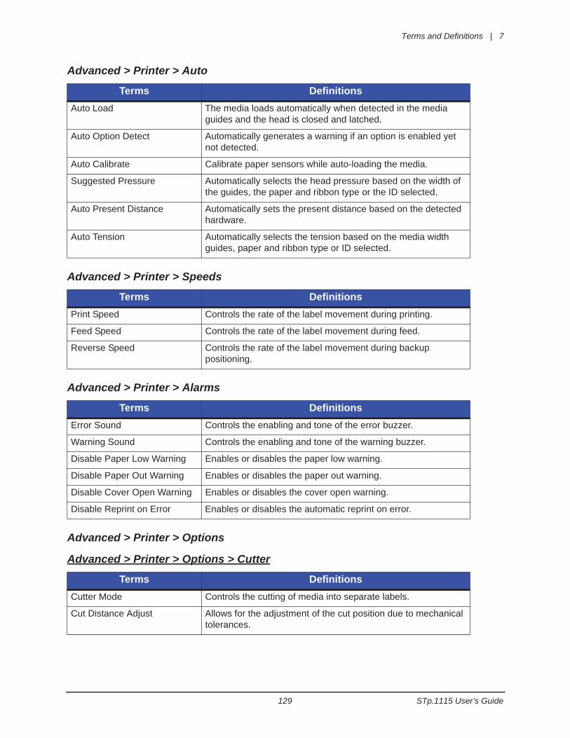
Terms and Definitions | 7
129 STp.1115 User’s Guide
Advanced > Printer > Auto
Advanced > Printer > Speeds
Advanced > Printer > Alarms
Advanced > Printer > Options
Advanced > Printer > Options > Cutter
Terms DefinitionsAuto Load The media loads automatically when detected in the media
guides and the head is closed and latched.
Auto Option Detect Automatically generates a warning if an option is enabled yet not detected.
Auto Calibrate Calibrate paper sensors while auto-loading the media.
Suggested Pressure Automatically selects the head pressure based on the width of the guides, the paper and ribbon type or the ID selected.
Auto Present Distance Automatically sets the present distance based on the detected hardware.
Auto Tension Automatically selects the tension based on the media width guides, paper and ribbon type or ID selected.
Terms DefinitionsPrint Speed Controls the rate of the label movement during printing.
Feed Speed Controls the rate of the label movement during feed.
Reverse Speed Controls the rate of the label movement during backup positioning.
Terms DefinitionsError Sound Controls the enabling and tone of the error buzzer.
Warning Sound Controls the enabling and tone of the warning buzzer.
Disable Paper Low Warning Enables or disables the paper low warning.
Disable Paper Out Warning Enables or disables the paper out warning.
Disable Cover Open Warning Enables or disables the cover open warning.
Disable Reprint on Error Enables or disables the automatic reprint on error.
Terms DefinitionsCutter Mode Controls the cutting of media into separate labels.
Cut Distance Adjust Allows for the adjustment of the cut position due to mechanical tolerances.
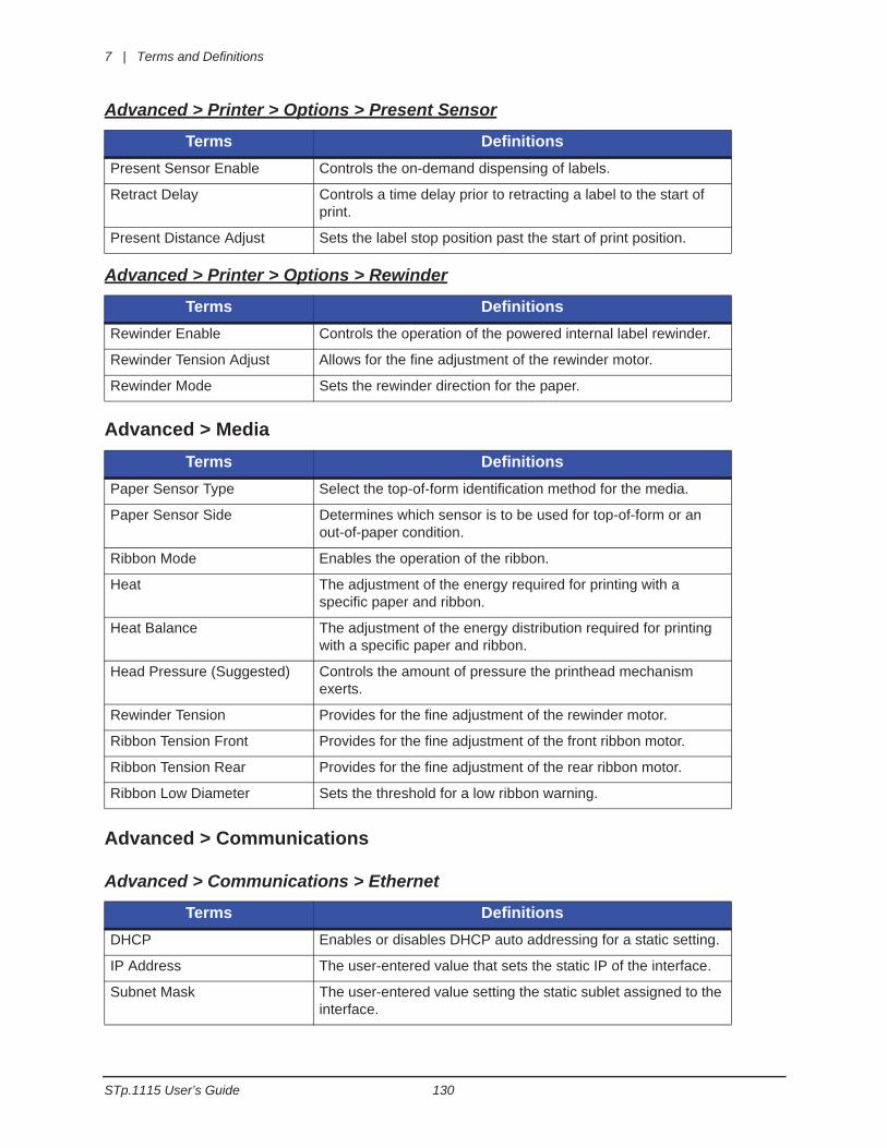
7 | Terms and Definitions
STp.1115 User’s Guide 130
Advanced > Printer > Options > Present Sensor
Advanced > Printer > Options > Rewinder
Advanced > Media
Advanced > Communications
Advanced > Communications > Ethernet
Terms DefinitionsPresent Sensor Enable Controls the on-demand dispensing of labels.
Retract Delay Controls a time delay prior to retracting a label to the start of print.
Present Distance Adjust Sets the label stop position past the start of print position.
Terms DefinitionsRewinder Enable Controls the operation of the powered internal label rewinder.
Rewinder Tension Adjust Allows for the fine adjustment of the rewinder motor.
Rewinder Mode Sets the rewinder direction for the paper.
Terms DefinitionsPaper Sensor Type Select the top-of-form identification method for the media.
Paper Sensor Side Determines which sensor is to be used for top-of-form or an out-of-paper condition.
Ribbon Mode Enables the operation of the ribbon.
Heat The adjustment of the energy required for printing with a specific paper and ribbon.
Heat Balance The adjustment of the energy distribution required for printing with a specific paper and ribbon.
Head Pressure (Suggested) Controls the amount of pressure the printhead mechanism exerts.
Rewinder Tension Provides for the fine adjustment of the rewinder motor.
Ribbon Tension Front Provides for the fine adjustment of the front ribbon motor.
Ribbon Tension Rear Provides for the fine adjustment of the rear ribbon motor.
Ribbon Low Diameter Sets the threshold for a low ribbon warning.
Terms DefinitionsDHCP Enables or disables DHCP auto addressing for a static setting.
IP Address The user-entered value that sets the static IP of the interface.
Subnet Mask The user-entered value setting the static sublet assigned to the interface.
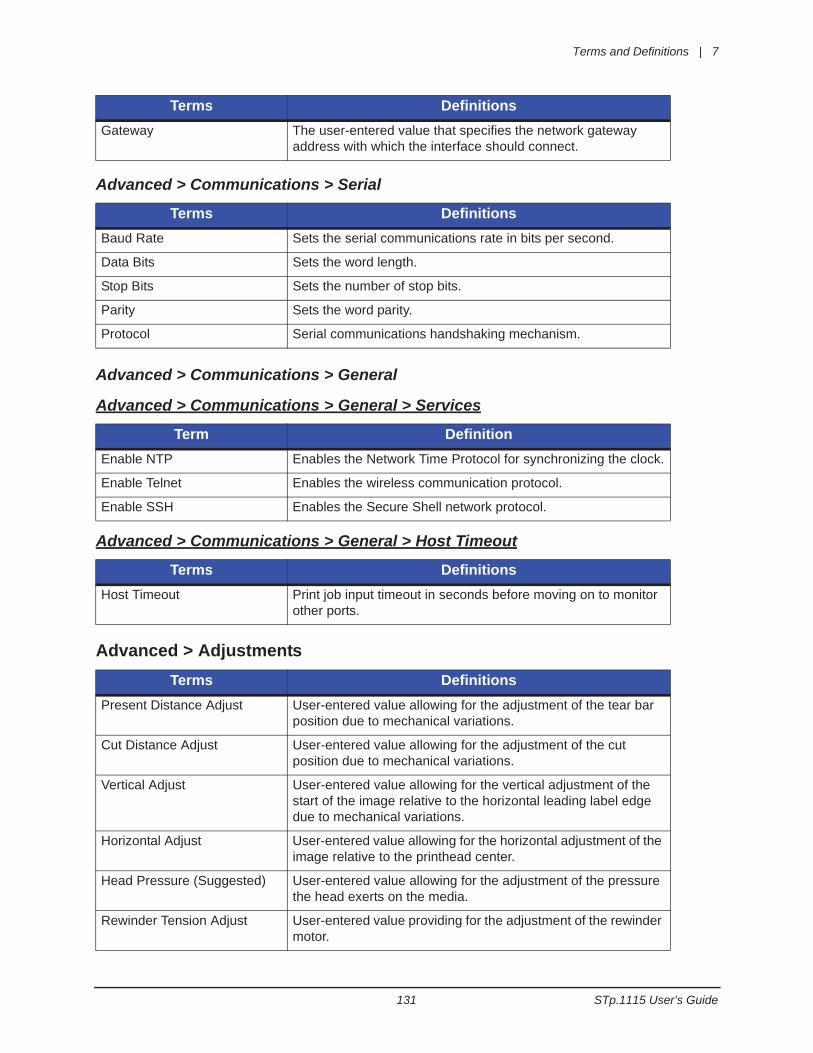
Terms and Definitions | 7
131 STp.1115 User’s Guide
Advanced > Communications > Serial
Advanced > Communications > General
Advanced > Communications > General > Services
Advanced > Communications > General > Host Timeout
Advanced > Adjustments
Gateway The user-entered value that specifies the network gateway address with which the interface should connect.
Terms DefinitionsBaud Rate Sets the serial communications rate in bits per second.
Data Bits Sets the word length.
Stop Bits Sets the number of stop bits.
Parity Sets the word parity.
Protocol Serial communications handshaking mechanism.
Term DefinitionEnable NTP Enables the Network Time Protocol for synchronizing the clock.
Enable Telnet Enables the wireless communication protocol.
Enable SSH Enables the Secure Shell network protocol.
Terms DefinitionsHost Timeout Print job input timeout in seconds before moving on to monitor
other ports.
Terms DefinitionsPresent Distance Adjust User-entered value allowing for the adjustment of the tear bar
position due to mechanical variations.
Cut Distance Adjust User-entered value allowing for the adjustment of the cut position due to mechanical variations.
Vertical Adjust User-entered value allowing for the vertical adjustment of the start of the image relative to the horizontal leading label edge due to mechanical variations.
Horizontal Adjust User-entered value allowing for the horizontal adjustment of the image relative to the printhead center.
Head Pressure (Suggested) User-entered value allowing for the adjustment of the pressure the head exerts on the media.
Rewinder Tension Adjust User-entered value providing for the adjustment of the rewinder motor.
Terms Definitions
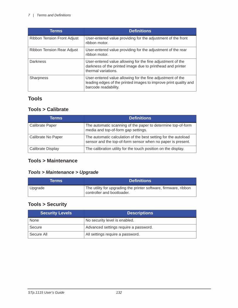
7 | Terms and Definitions
STp.1115 User’s Guide 132
Tools
Tools > Calibrate
Tools > Maintenance
Tools > Maintenance > Upgrade
Tools > Security
Ribbon Tension Front Adjust User-entered value providing for the adjustment of the front ribbon motor.
Ribbon Tension Rear Adjust User-entered value providing for the adjustment of the rear ribbon motor.
Darkness User-entered value allowing for the fine adjustment of the darkness of the printed image due to printhead and printer thermal variations.
Sharpness User-entered value allowing for the fine adjustment of the leading edges of the printed images to improve print quality and barcode readability.
Terms DefinitionsCalibrate Paper The automatic scanning of the paper to determine top-of-form
media and top-of-form gap settings.
Calibrate No Paper The automatic calculation of the best setting for the autoload sensor and the top-of-form sensor when no paper is present.
Calibrate Display The calibration utility for the touch position on the display.
Terms DefinitionsUpgrade The utility for upgrading the printer software, firmware, ribbon
controller and bootloader.
Security Levels DescriptionsNone No security level is enabled.
Secure Advanced settings require a password.
Secure All All settings require a password.
Terms Definitions
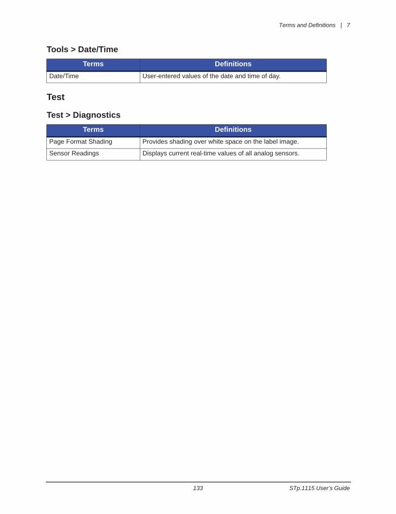
Terms and Definitions | 7
133 STp.1115 User’s Guide
Tools > Date/Time
Test
Test > Diagnostics
Terms DefinitionsDate/Time User-entered values of the date and time of day.
Terms DefinitionsPage Format Shading Provides shading over white space on the label image.
Sensor Readings Displays current real-time values of all analog sensors.

7 | Terms and Definitions
STp.1115 User’s Guide 134
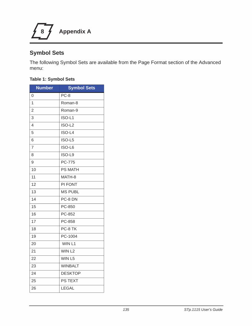
135 STp.1115 User’s Guide
8 Appendix A
Symbol SetsThe following Symbol Sets are available from the Page Format section of the Advanced menu:
Table 1: Symbol Sets
Number Symbol Sets0 PC-8
1 Roman-8
2 Roman-9
3 ISO-L1
4 ISO-L2
5 ISO-L4
6 ISO-L5
7 ISO-L6
8 ISO-L9
9 PC-775
10 PS MATH
11 MATH-8
12 PI FONT
13 MS PUBL
14 PC-8 DN
15 PC-850
16 PC-852
17 PC-858
18 PC-8 TK
19 PC-1004
20 WIN L1
21 WIN L2
22 WIN L5
23 WINBALT
24 DESKTOP
25 PS TEXT
26 LEGAL
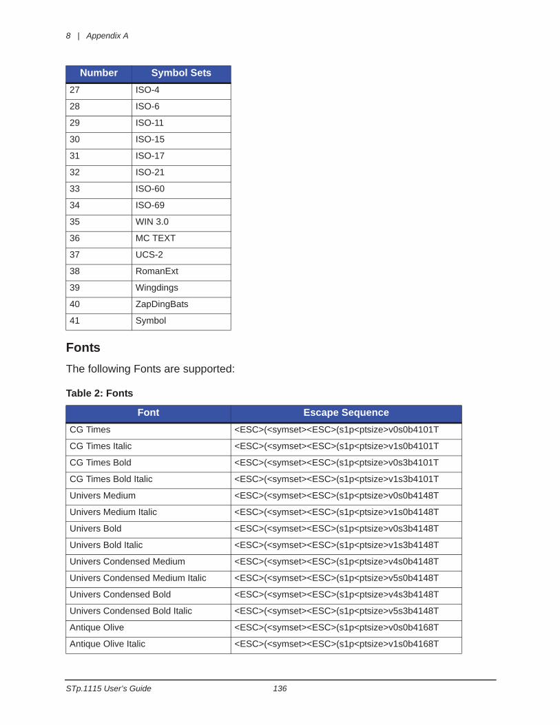
8 | Appendix A
STp.1115 User’s Guide 136
FontsThe following Fonts are supported:
Table 2: Fonts
27 ISO-4
28 ISO-6
29 ISO-11
30 ISO-15
31 ISO-17
32 ISO-21
33 ISO-60
34 ISO-69
35 WIN 3.0
36 MC TEXT
37 UCS-2
38 RomanExt
39 Wingdings
40 ZapDingBats
41 Symbol
Font Escape SequenceCG Times <ESC>(<symset><ESC>(s1p<ptsize>v0s0b4101T
CG Times Italic <ESC>(<symset><ESC>(s1p<ptsize>v1s0b4101T
CG Times Bold <ESC>(<symset><ESC>(s1p<ptsize>v0s3b4101T
CG Times Bold Italic <ESC>(<symset><ESC>(s1p<ptsize>v1s3b4101T
Univers Medium <ESC>(<symset><ESC>(s1p<ptsize>v0s0b4148T
Univers Medium Italic <ESC>(<symset><ESC>(s1p<ptsize>v1s0b4148T
Univers Bold <ESC>(<symset><ESC>(s1p<ptsize>v0s3b4148T
Univers Bold Italic <ESC>(<symset><ESC>(s1p<ptsize>v1s3b4148T
Univers Condensed Medium <ESC>(<symset><ESC>(s1p<ptsize>v4s0b4148T
Univers Condensed Medium Italic <ESC>(<symset><ESC>(s1p<ptsize>v5s0b4148T
Univers Condensed Bold <ESC>(<symset><ESC>(s1p<ptsize>v4s3b4148T
Univers Condensed Bold Italic <ESC>(<symset><ESC>(s1p<ptsize>v5s3b4148T
Antique Olive <ESC>(<symset><ESC>(s1p<ptsize>v0s0b4168T
Antique Olive Italic <ESC>(<symset><ESC>(s1p<ptsize>v1s0b4168T
Number Symbol Sets
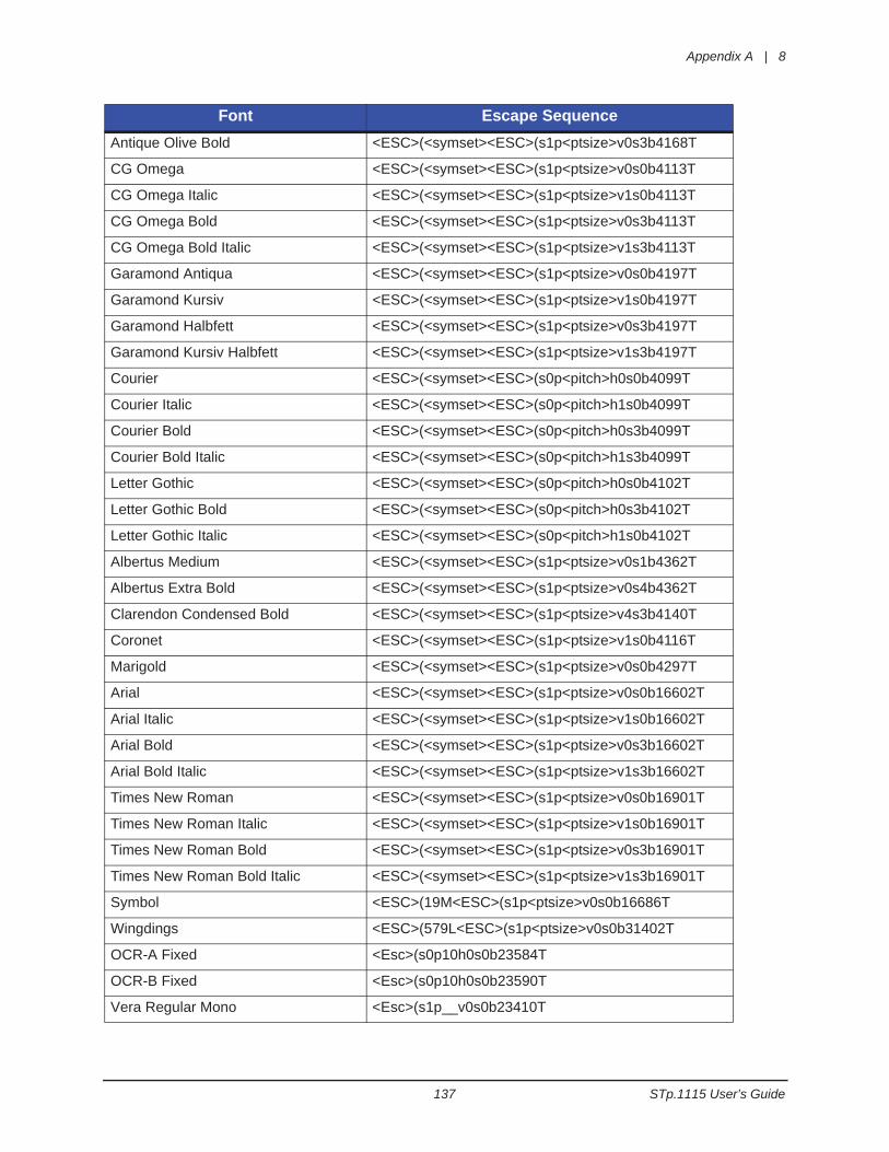
Appendix A | 8
137 STp.1115 User’s Guide
Antique Olive Bold <ESC>(<symset><ESC>(s1p<ptsize>v0s3b4168T
CG Omega <ESC>(<symset><ESC>(s1p<ptsize>v0s0b4113T
CG Omega Italic <ESC>(<symset><ESC>(s1p<ptsize>v1s0b4113T
CG Omega Bold <ESC>(<symset><ESC>(s1p<ptsize>v0s3b4113T
CG Omega Bold Italic <ESC>(<symset><ESC>(s1p<ptsize>v1s3b4113T
Garamond Antiqua <ESC>(<symset><ESC>(s1p<ptsize>v0s0b4197T
Garamond Kursiv <ESC>(<symset><ESC>(s1p<ptsize>v1s0b4197T
Garamond Halbfett <ESC>(<symset><ESC>(s1p<ptsize>v0s3b4197T
Garamond Kursiv Halbfett <ESC>(<symset><ESC>(s1p<ptsize>v1s3b4197T
Courier <ESC>(<symset><ESC>(s0p<pitch>h0s0b4099T
Courier Italic <ESC>(<symset><ESC>(s0p<pitch>h1s0b4099T
Courier Bold <ESC>(<symset><ESC>(s0p<pitch>h0s3b4099T
Courier Bold Italic <ESC>(<symset><ESC>(s0p<pitch>h1s3b4099T
Letter Gothic <ESC>(<symset><ESC>(s0p<pitch>h0s0b4102T
Letter Gothic Bold <ESC>(<symset><ESC>(s0p<pitch>h0s3b4102T
Letter Gothic Italic <ESC>(<symset><ESC>(s0p<pitch>h1s0b4102T
Albertus Medium <ESC>(<symset><ESC>(s1p<ptsize>v0s1b4362T
Albertus Extra Bold <ESC>(<symset><ESC>(s1p<ptsize>v0s4b4362T
Clarendon Condensed Bold <ESC>(<symset><ESC>(s1p<ptsize>v4s3b4140T
Coronet <ESC>(<symset><ESC>(s1p<ptsize>v1s0b4116T
Marigold <ESC>(<symset><ESC>(s1p<ptsize>v0s0b4297T
Arial <ESC>(<symset><ESC>(s1p<ptsize>v0s0b16602T
Arial Italic <ESC>(<symset><ESC>(s1p<ptsize>v1s0b16602T
Arial Bold <ESC>(<symset><ESC>(s1p<ptsize>v0s3b16602T
Arial Bold Italic <ESC>(<symset><ESC>(s1p<ptsize>v1s3b16602T
Times New Roman <ESC>(<symset><ESC>(s1p<ptsize>v0s0b16901T
Times New Roman Italic <ESC>(<symset><ESC>(s1p<ptsize>v1s0b16901T
Times New Roman Bold <ESC>(<symset><ESC>(s1p<ptsize>v0s3b16901T
Times New Roman Bold Italic <ESC>(<symset><ESC>(s1p<ptsize>v1s3b16901T
Symbol <ESC>(19M<ESC>(s1p<ptsize>v0s0b16686T
Wingdings <ESC>(579L<ESC>(s1p<ptsize>v0s0b31402T
OCR-A Fixed <Esc>(s0p10h0s0b23584T
OCR-B Fixed <Esc>(s0p10h0s0b23590T
Vera Regular Mono <Esc>(s1p__v0s0b23410T
Font Escape Sequence
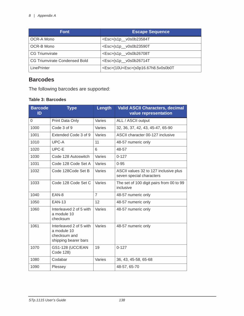
8 | Appendix A
STp.1115 User’s Guide 138
BarcodesThe following barcodes are supported:
Table 3: Barcodes
OCR-A Mono <Esc>(s1p__v0s0b23584T
OCR-B Mono <Esc>(s1p__v0s0b23590T
CG Triumvirate <Esc>(s1p__v0s0b26708T
CG Triumvirate Condensed Bold <Esc>(s1p__v0s0b26714T
LinePrinter <Esc>(10U<Esc>(s0p16.67h8.5v0s0b0T
Barcode ID
Type Length Valid ASCII Characters, decimal value representation
0 Print Data Only Varies ALL / ASCII output
1000 Code 3 of 9 Varies 32, 36, 37, 42, 43, 45-47, 65-90
1001 Extended Code 3 of 9 Varies ASCII character 00-127 inclusive
1010 UPC-A 11 48-57 numeric only
1020 UPC-E 6 48-57
1030 Code 128 Autoswitch Varies 0-127
1031 Code 128 Code Set A Varies 0-95
1032 Code 128Code Set B Varies ASCII values 32 to 127 inclusive plus seven special characters
1033 Code 128 Code Set C Varies The set of 100 digit pairs from 00 to 99 inclusive
1040 EAN-8 7 48-57 numeric only
1050 EAN-13 12 48-57 numeric only
1060 Interleaved 2 of 5 with a module 10 checksum
Varies 48-57 numeric only
1061 Interleaved 2 of 5 with a module 10 checksum and shipping bearer bars
Varies 48-57 numeric only
1070 GS1-128 (UCC/EAN Code 128)
19 0-127
1080 Codabar Varies 36, 43, 45-58, 65-68
1090 Plessey 48-57, 65-70
Font Escape Sequence
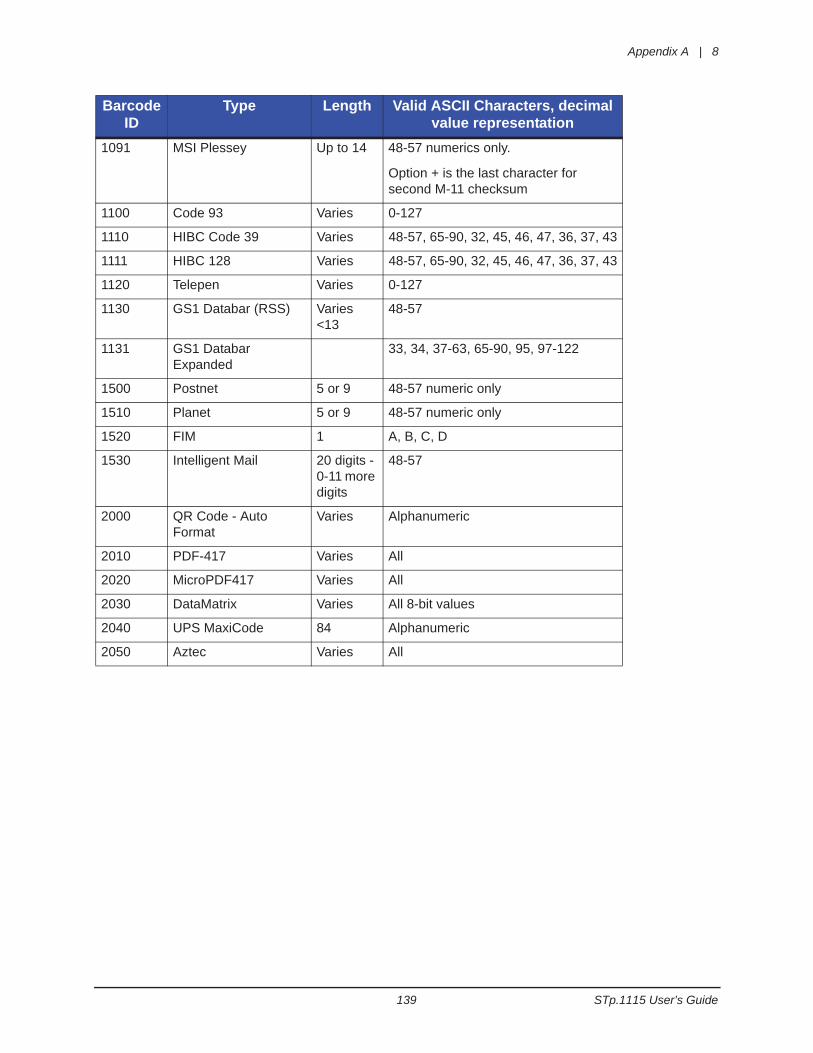
Appendix A | 8
139 STp.1115 User’s Guide
1091 MSI Plessey Up to 14 48-57 numerics only.
Option + is the last character for second M-11 checksum
1100 Code 93 Varies 0-127
1110 HIBC Code 39 Varies 48-57, 65-90, 32, 45, 46, 47, 36, 37, 43
1111 HIBC 128 Varies 48-57, 65-90, 32, 45, 46, 47, 36, 37, 43
1120 Telepen Varies 0-127
1130 GS1 Databar (RSS) Varies <13
48-57
1131 GS1 Databar Expanded
33, 34, 37-63, 65-90, 95, 97-122
1500 Postnet 5 or 9 48-57 numeric only
1510 Planet 5 or 9 48-57 numeric only
1520 FIM 1 A, B, C, D
1530 Intelligent Mail 20 digits - 0-11 more digits
48-57
2000 QR Code - Auto Format
Varies Alphanumeric
2010 PDF-417 Varies All
2020 MicroPDF417 Varies All
2030 DataMatrix Varies All 8-bit values
2040 UPS MaxiCode 84 Alphanumeric
2050 Aztec Varies All
Barcode ID
Type Length Valid ASCII Characters, decimal value representation