strata vi power supply installation...
TRANSCRIPT

TOSHIBA SYSTEM PRACTICES ELECTRONIC KEY TELEPHONE SYSTEM
POWER SUPPLY
AND
BACK-UP BATTERY
SECTION 100-006-250 POWER SUPPLY INSTALLATION
®
INSTALLATION INSTRUCTIONS
01 01.rn
01.20 01.30 02 02.01
02.10 02.20 02.30 02.40
SECTION 100-006-250 POWER SUPPLY INSTALLATION
POWER SUPPLY (EPSA) & BACK-UP BATTERY (PBBU)
INSTALLATION INSTIUJCTIONS
TABLE OF CONTENTS
TABLE OF CONTENTS ••••••••••••••••••••• , • , , •• ILLUSTRATION LIST ••••••••••.••••••••••••••••• POWEH SUPPLY MOUNTING ••••••••••••••••••••••••
PREPARING MOUNTING SURFACE ••••••••••• , •••••• ENC:LQSED HAHDWARE LIST • • • • • • ••••••••••••••• SECURING Tl!E EPSA •••••••..••.••••••••••••• FUSE PROTECTlON • • • • • • • . • . • •••••••••••••••
BATTERY BACK-UP INSTALLATION •.••••••••••.•• , •• GENERAL •••••••••••••••••.••.••••.••••••• TABLE A--MINDWM WIRE GAUGE •••••••••••• , • PBBU INSTALL,\TlON ••••••••.••..••.•••••••••• REQUIRED DECALS & TAGS .................... . BATTERY CONNECTION •••••••••••••••••••••••• INSTALLATION FJNALIZATION ••.....••••••••••••••
ILLUSTRATION LEST
i 1 1 1 1 2 3 3 5 5 'l 'l 8
FIGURE SUBJECT PAGE
l EPSA • • • • • • • • • • • • • • . • • • • • • • • • • l 2 TOGGLE BOLT • • • • • • • • . • • • • • • . • • • • • 1 3 INSTALLING TOGGLE BOLT •.••.•..•.••• 2 4 LOOS£ TOGGLE BOLT • • • • • . • • ••.••••• 2 5 TIGHTENED TOGGLE BOLT • . . . . . . • . . . . • . 2 6 EPSA • • • • • • • • • • • • • • • • • • • • •• , • • • 2 7 PBBU PCB ••••••••••••••••••••••• 3 8 EPSA • • • • • • • • • • • • • • • • • • • • • • . • • • 4 9 EPSA • • • • • . • • • • • • • • • • • • •••••.• 6
10 OPEN t;PSA •.•••••.•••...•.•...••• 6 11 PBBU IN PLACE • • • • • • • • • • • • • . • • • • • • 6 12 WifWlCl DIAGRAM • • • • • • • • • • • • • • • • • • • 8 13 BATTERY ATTACl!MENT ••••••••••.•••• 8

01 POWER SUPPLY MOUNTING
01.01 AH models of the External Powe!' Supply Assembly (EPSA) are equipped with a built-in wall mounting bracket, as shown !n Figure 1, to allow the EPSA to be mounted on a wall or other flat, vertical surface.
FIGURE l
01*10 Preparing the M.oontlng Surfaee
Ul.11 Unpaek and inspect the EPSA and the enelosed hardvvare. The following hardware, which is required to mount and connect the EPSA to the system, is supp.lied with each EPSA.
FIGURE 2
SECTION 100-006-250 POWER SUPPLY INSTALLATION
ENCLOSED HARDWARE
Quantity
2 T.C. Toggler l'•'aU Fasteners (figure 2).
2 # 14 Hex !fond Sbeet 'YI et al s,~rews.
l l 11726lHl01 (to
fasteners
Fuse (spare) P/N arnp, \Fl., 5
(spare) P/N 10 amp,
32 VDC). rn A\vG, ;1 wire Jacketed Cable ( 54 inches).
01.12 Choose a suitable location on u verttcal surface for the EPSr\, and a!ta('}1 the P/N Il726tHlOl t0mplate to that locntion temporarily. Use a spirit level that the indicated
01.13 mounting marked
Plnce punch marks on sul'face through the
driH!ng on
the
the
01.14 the two punch marks with nn I/8-ineh drill bit.
01.15 With a 5/HHnch bit, drill through the mounting surface to complete the anchoring holes. Ol.20 Soot.wing the E?SA
01.21 Press the anchoring legs of a toggler together and insert them into one of the anchoring holes, as shown in Figure :J.
Ul.22 Insert the toggler into the hole until the neck flange is flush with the mounting surface. If it ls difficult to insert it completely by hand, tap it lightly with lmmmer.
- l -

SECTION 100-006-250 POWER SUPPLY INSTALLATION
FIGURE 3
CU.23 Insert a toggler key into the small hole in the neck of the fastener, as shown in Figure 4. This should cause the anchoring legs to "pop" open. Even if the mounting surface is too thick to permit the to open fully. adequate support for the EPSA should be provided when the screws are in ()lace. Remove the togglcr key.
FIGURE 4
01.24 Repeat the steps outlined in Paragraphs 01.21 to 01.23 for the second hole.
01.25 Thread the #14 hex head sheet metal screws into the small holes in the center of the togglers. Leave approximately 3/HHnch clearance between the bottom of each screw head and the mounting surface (Figure 5),
FIGURE 5
01.26 Aligu the EPSA mounting br,icket's holes with the sheet met;ll screws as shown iu Figure 6. Pince the EPSA agninst the mounting surfacE' with the screws protruding through the hole~'>·
FIGURE 6
01.27 Lower the EPSA so that the narrower portions of the holes slip over the screws and the weight of the EPSA is supported. Tighten the screws.
1n.:m Fuse Proteetioo for the EPSA
IH.:U Remove the spare fuse;; from the hardware carton.
- 2 -
01.32 Place the spare lO amp DC fuse in the center fuse storage clip located on the side panel of the EPSA {Figure 6).
U.33 Place the spare 5 amp SL0-13LO AC fuse in the clip below the DC fuse clip.
01.34 Remove and inspect the fuses that were shipped inside the EPSA. If the visual inspection reveal<> a defective fuse, remove the appropriate spare from its storage clip and replace the defective fuse. (Order another spare fuse.}
02 BATTERY BACK-UP INSTALLATION
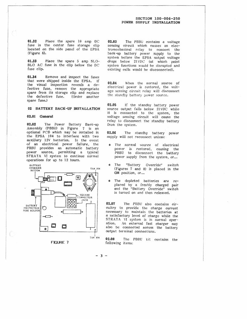
02.02 The Power Battery Back-up Assembly (PBBU) in Figure 7 is an optional PCB which may be installed in the EPSA 104 to interface with two auxiliary 12V batteries. In the event of an electrical power failure, the PBBU provides an automatic battery power source, permitting a typical STRATA VI system lo continue normal operations for up to 12 hours.
c c
FIGURE 1
SECTION 100-006-250 POWER SUPPLY INSTALLATION
02.03 The PBBU contains a voltage sensing circuit which causes an electromechanical relay to connect the back-up battery power supply to the system before the EPSA output voltage drops below 21 VDC (at which point system functions would be disrupted and existing calls would he disconnected).
02.04 When the normal source of electrical power is restored, the voltage sen;;ing circuit relny will <liseormect the standby battery power source,
f}£.65 If the standby battery power source output falls below 21 VDC while it is connected to the system, the voltage sensing circuit will cause the relay to disconnect the standby battery from the system.
02.06 The standby battery power supply will not reconnect unless:
(I; The normal source power is restored, PBBU to disconnect power supply from the
of electrical causing the the battery
system, or ...
e The "Battery Override" switch (Figures 7 and 8) is placed in the OM position, or ...
e The depleted batteries are replaced by a freshly charged pair and the "Battery Override" switch is turned on and then released.
02.01 The PBBU also contains circuitry to provide the charge current necessary to maintain the batteries at a satisfactory level of charge while the STRATA Vl system is in normal operation. An external fast charger may also be eonnected across the battery output term inai connections.
02.08 The PBBU kit contains the following items:
- 3 -

SECTION 100-006-250 POWER SUPPLY INSTALLATION
DC FUSE
0 10A 32V
F,8
AC FUSE
0 AC LINE
AC ON ®
nm:vJINAL STRIP
t oc ON ©
I
Pll ! 0! I U! I !
SA1'TERY
SACK UP
FIGURE 8
o PBBU--Powel' battery backup PCB.
G Fuse-A spare battery protection fuse.
o Cable Clamp-A clamp which may secure the wiring th<; EPSA.
7/HHn. cable be needed to hurnes5 inside
o "PBBU-REV 3''--An adhcsive-backnd decal to he placed on the front face of the EPSA.
o Warning Tag--A warning tag to bf: atta<-hed to the EPSA 115VAC power cord.
02.09 ln addition to those items supplied in the PBBU kit, the following additional items are needed to install a P!313U in an EPSA:
o Two 8'1tterirs-Two l 2V/80 amphour, leed-11<'id, iwtomotivr:-type, maintenctne>e-free batteries are recommended. The procedures in Parsgraµh 02.54> assurne batteries with sidi::-mounted terminals are used.
e Battery Rad; and Separator-A battet·y rack and separntor should be used to seeure the batteries to prevent tipping mid spilling of hattery acid or acddental shorting of the battery terminals.
e Two-Wire Conneeti ng Cahle···-A 2-w ire c:onneeUng cable terminating at one enJ with 3/8-in. ring terrnrnab iHHi >lt the other <:rtd With 1 '8-in, hooked soade terminals is required h) provide the connection
between the batteries and the £PSA. The mm1mum wire size must be determined by the loop length of the connecting cnhle us indi<~aterl in Table A.
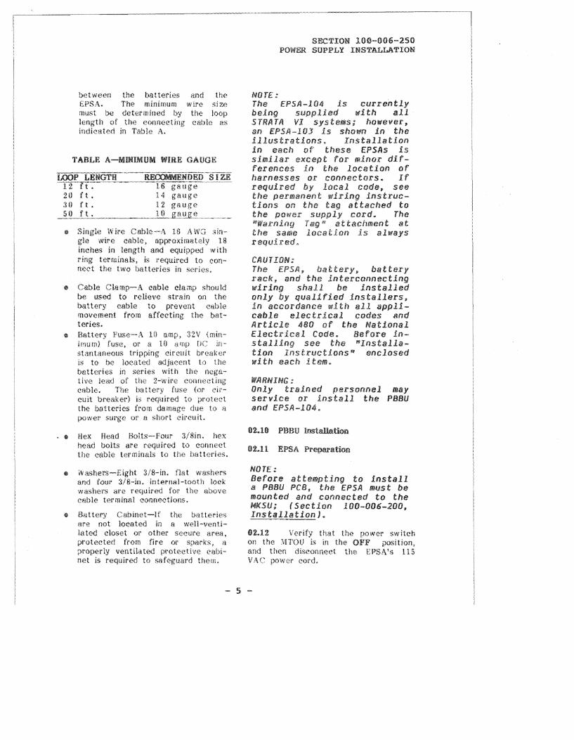
TABLE A-ll.UlUMUM WIRE GAUGE
2 ll ft • :rn ft.
14 12 gauge
o Single Wire Cable ·-A 16 A WG 3ingle wire cable, approximately 18 inches in length and equ!ppt,'<.l with ring terminals, is requfred to connect the two batteries in series.
e Cable Clamp-A cable clamp should be used to relieve strain on the battery cable to prevent cable movement from affecting the butteries.
e Battery Fuse-A Hl amp, 32V {minimum) or a IO amp fJC instantarwous tripping circuit. breaker is to be located adjacent to the batteries in series with the tive lead of the 2-wire cable. The battery fuse (or circuit breaker) b required to protect the batteries from damage due to a power surge or a short eireuit.
. e Hex !lead Bolts-Four 3/8in. hex t1ead bolts are required to connect the eahle terminals to tbe batteries.
e iVashers-Eight 3/8-in. flat washers and four 3/8-in. internal-tooth loek washers are for the above cable terminal eonneetions,
e Battery Cabinet-If the batteries are not located in a well-ventila ted closet or other secure area, protected from fire or sparks, a properly ventihtted prnteet!ve cabinet is required to safeguard them.
NOTE:
SECTION 100-006-250 POWSR SUPPLY INSTAL~TION
The EPSf.l-104 is currently being supplied with all STRATA VI sys however, an EP5f.l-lOJ is shown in the illustrations. Installation in each of these EPSAs is similar except for minor differemces in the location of harnesses or connectors. If required local code, see the wiring instruc-tions an tho tag attached to the supply cord. The
" attachment at the same location is always
CfliJTION: The EPSA, battery, battery .rack, end the intercormecting wiring shall be irtstalled only by qualified installers, in accordance with ell applicable electrical codes and Article 480 of the National Electrical Code. Before installing see the "Installation lnstructionsn enclosed with each item.
WARNING: Only trained personnel may service or install the PBBU and EPSA-104.
NOTE: Before attempting to install a PBBU PCB, the EPSA must be mounted and connected to the MKSU; (Section 100-006-200, InstaJ)atlord.
02.12 Verify that the powe!' switch on the MTOU is in the OFF position, and then diseonneet the EPSA's 115 VAC power cord.
- 5 -
SECTION 100-006-250 POWER SOPPLY INSTALLATION
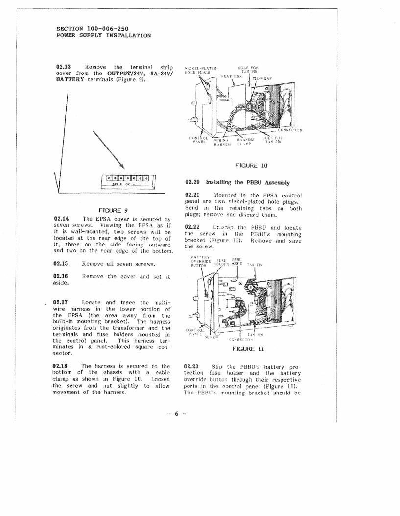
02.13 Remove the terminal strip cover from the OUTPIJT/24V, 8A-24V/ BATTERY terminals (Figure SJ.
FIGURE 9 02.14 The EPSA cover ls secured bv seven screws. Viewing the EPSA as fr it is wall-mounted, .two screws will be located at the rear edge of the top of it, three on the c;i<le facing outward and two on the rear edge of the bottom.
02.15
02.16 aside.
Remove all seven screws.
Hemove the eover 1md set it
02.l'l Locate and trace the multiwire harness in the k>wt:r portion of the EPS.\ (the area away from the built-in mounting bracket). The harness originates from the transformer and the terminals and fuse holders mounted in the control pane!. This harness terminates in a rust-colored square conneetor.
02.18 The harness is secured to the bottom of the chassis with a cable clamp as shown in Figure lfl. Loosen the screw and nut slightly to allow •novement of the harness.
FIGURE IO
1}2.21 Mounted i.n the EPSA control panel are two nickel-plated hole plugs. Bend in the retarnrng tabs on both plugs; remov0 and discurd them.
n.22 the screw bracket the screw.
the PBBU and locate i'l the PB8U's mounting
11). Remove 11nd save
FIGURE 11
02.23 the PBBU's battery protection fuse holder and the battery override button through their respective ports in the control panel (Figure 11). Tile PBBU's mounting br•acket should be

flush against the rear of the control p1rnel with the fuse holder and override button protruding through it. The harness should flow around the PBBU PCB, with no wires beneath it.
02.24 Align the two tan-colored PBBU pins with the two holes in the heat sink (Figure 10). Pres,;; the pins into the holes until they catch and hold the PBBU PCB.
®2.25 Use the previously removed screw and seeure the PBBU mounting bracket to the control panel. See Figure 11.
02.26 Plug the rust-colored (•onneetor into the nine-hole jack in the center of the PBBtJ PCB. Do not force the connector's prongs into the jack, they are ki~yed so that they can be mined in only one position.
02.27 Replace the EPSA cover and secure it with the seven screws originally removed.
02.28 Press in the battery override button (Figure 8). If it cat<~hes and stays in, press it again to 0ause it to release and protrude out of the control panel. Out is off, and the position of the button must be in for the EPSA to operate normaHy.
02.29 Remove the spare fuse from the PBBU kit. If the original fuse is missing or defective, replace it with the spare. If not, put the sparn fuse in the holder located on the side of the EPSA away from the control pnneL
02.31 Remove the warning tag from the kit an<! tie it to the power cord where it emerges from the EPSA.
@2.32 /\ "Pf:WlHlEV 3" decal must be plaee<I on the control panel of the
SECTION 100-006-250 POWER SUPPLY INSTALLATION
EPSA. Remove the decal from the kit, µeel the backing off, and place it on the control pane! (Figure 8).
oi.@ BatteTy Cooneetfon
CAUTION: Do not attempt to connect the b<ltteries to the EPSA while the AC card is plugged in, or thaut the EPSA being connected to the MKSU. Do not connect the 2-wire cable to the batteries before connecting it to the EPSA. Once the batteries are connected to the f P5A the 24V 8A terminals are live.
H.41 Seleet a location for the bntt111·ies netir the EPSA. The length of the cuble connecting them to the EPSA wlll determine the minimum
wire which ean be used in the See Table A.
NOTE: The area in which the batteries are to be located must be wall ventilated to prevent a dangerous accumulation of battery gases. The batteries must also be protected from moisture and extreme temperatures.
02.42 Secure the batteries in the battery rack and separator, which should bc located in a minimum access area, sueh ns a closet or a well ventilated cabinet. 02.43 Verify that the battery override button is in the OFF position (out).
12.44 Loosen the two screws on the terminal strip identified as 24V/BATTERY.
Attach the cable's two spade tips to t hcse eonnec~tors. Eueh wire.
- 1 -
SECTION 100-006-250 POWER SUPPLY INSTALLATION
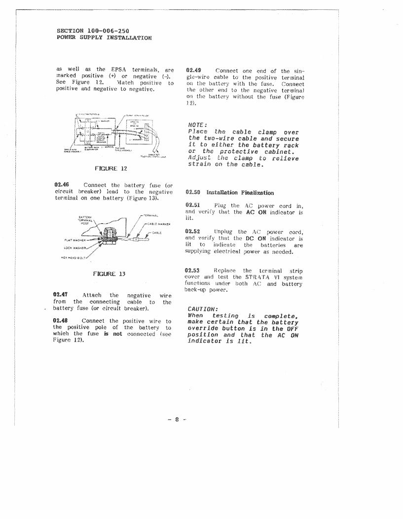
as well as the EPSA terminals, are marked positive (+) or negative (-). See Figure 12. \>latch positive to positive and neglltive to negative.
FIGURE 12
02.46 Connect the battery fuse (ol' circuit hreuker) !eod to the negative terrninol on one battet·y (Figure 13}.
FIGURE 13
02.47 Attach the negative wire from the connecting cable to the battery fuse (or circuit breaker).
02.48 Connect the positive wire to the positive pole of the battery to which the fuse is not connected (see Figure 12).
02.49 Connect one end of the single-wire cable to the positive terminal on the battery with the fuse. Connect the other end to Uw negative terminal on the h>ittcry without the fuse (Figure 1 2l.
NOTE:: Place the cable clamp over the two-wire cable and secure it to either the battery rack or the tective cabinet.
02.51 JlHQ
lit.
cl<iimp to relieve on the cable.
Plug the AC power cord in, lhat the AC ON indicator is
02.5% Llnplug the AC power cord, and verify that the DC ON indicator !,.; lit to indicate the batteries are supplying elect?ical ~iower as needed.
02.53 Replnee the terminal strip cover and test the STR l\TA VI system funcl ions under both :\C and battery back-up power.
CAUTION: When testing is complete. make certain that the battery override button is in the OFF position and that the AC ON indicator is lit.