strong light control systems - eprad rev 1.02.pdf · strong light control systems installation,...
TRANSCRIPT

TM
Cinema ProductsCinema Products
Strong Light Control Systems
Installation, Setup, and Operation Manual(Covers LCS, CLD, AD, LDP, and AP Models)
Revision 1.02Jan 2006

Strong Light Control SystemsInstallation, Setup and Operation Manual
PR011 Revision 1.02This manual describes the installation, setup and operation of the LCS, AD, CLD, LDP,and AP Dimmer and auxiliary cabinets.
Optional CineNet and related equipment is covered in the following product referencemanuals:
! PR001 CNA Installation Manual! PR002 CNA-200 Setup and Operation Manual! PR003 CNA-150 Setup and Operation Manual! PR004 CNA-100 Setup and Operation Manual! PR005 QDC-400 Setup and Operation Manual! PR006 ACP-50 Installation and Setup Manual! PR007 RVC-5 Installation and Setup Manual! PR008 PCI-64 Gateway Interface Installation! PR009 CineNet Host Software! PR010 RCM-10/RSM-10/RSM-20 Installation and Operation Manual! PR011 Strong Dimmer Installation, Setup, and Operation Manual! PR012 eCNA-100 Automation Manual! PR013 eCNA-150 Automation Manual! PR014 eCNA-200 Automation Manual! PR016 Strong FP350 Installation and Operation Manual! PR017 Eprad FP350 Installation and Operation Manual! PR018 Paging system Setup and Installation Manual! PR019 VNC Setup and Operation Manual! PR020 CineSuite Installation and Operation Manual
WarrantyCineNet automation products, sold by STRONG INTERNATIONAL, are warranted against defects inmaterials and workmanship for one year from the date of purchase. There are no other express or impliedwarranties and no warranty of merchantability or fitness for a particular purpose.
During the warranty period, STRONG INTERNATIONAL will repair or, at its option, replace componentsthat prove to be defective, provided the unit is shipped prepaid to the manufacturer directly or via andauthorized distributor. Not covered by this warranty are defects caused by modification, misuse oraccidents and any further damage caused by inadequate packing for service return.
STRONG INTERNATIONAL's obligation is restricted to the repair or replacement of defective parts andunder no circumstances will STRONG INTERNATIONAL be liable for any other damage, either direct orconsequential.
Information in this document is subject to change without notice. No part of this document may bereproduced or transmitted in any form or by any means, electronic or mechanical, for any purpose, withoutthe express written permission of STRONG INTERNATIONAL.
© 1997 - 2006 STRONG INTERNATIONAL. All rights reserved.

Table of Contents:
Introduction . . . . . . . . . . . . . . . . . . . . . . . . . . . . . . . . . . . . . . . . . . . . . . . . . . . . . . . . . . . . . . . . . 5System components . . . . . . . . . . . . . . . . . . . . . . . . . . . . . . . . . . . . . . . . . . . . . . . . . . . . . . 6QDC-400 Dimmer Controller . . . . . . . . . . . . . . . . . . . . . . . . . . . . . . . . . . . . . . . . . . . . . . 6
The QDC and luminescence . . . . . . . . . . . . . . . . . . . . . . . . . . . . . . . . . . . . . . . . . 7QDC Operation . . . . . . . . . . . . . . . . . . . . . . . . . . . . . . . . . . . . . . . . . . . . . . . . . . . 9
37627 Analog Dimmer Controller . . . . . . . . . . . . . . . . . . . . . . . . . . . . . . . . . . . . . . . . . . 1037627 Operation . . . . . . . . . . . . . . . . . . . . . . . . . . . . . . . . . . . . . . . . . . . . . . . . . 10
The 37870 2K Watt Dimmer Module . . . . . . . . . . . . . . . . . . . . . . . . . . . . . . . . . . . . . . . 10The 37670 2K Watt Dimmer Module . . . . . . . . . . . . . . . . . . . . . . . . . . . . . . . . . . . . . . . 10
Installation . . . . . . . . . . . . . . . . . . . . . . . . . . . . . . . . . . . . . . . . . . . . . . . . . . . . . . . . . . . . . . . . . 12Installation Guidelines . . . . . . . . . . . . . . . . . . . . . . . . . . . . . . . . . . . . . . . . . . . . . . . . . . . 12Dimmer Cabinet Mounting . . . . . . . . . . . . . . . . . . . . . . . . . . . . . . . . . . . . . . . . . . . . . . . 14Typical Wiring and Configuration . . . . . . . . . . . . . . . . . . . . . . . . . . . . . . . . . . . . . . . . . . 16Typical House and Stage Lights Wiring . . . . . . . . . . . . . . . . . . . . . . . . . . . . . . . . . . . . . 19Parallel 2K Watt Power Modules . . . . . . . . . . . . . . . . . . . . . . . . . . . . . . . . . . . . . . . . . . 20Transformer Wiring (LCS Dimmer Only) . . . . . . . . . . . . . . . . . . . . . . . . . . . . . . . . . . . . 22Multiple QDC-400 Control Boards . . . . . . . . . . . . . . . . . . . . . . . . . . . . . . . . . . . . . . . . . 23
Setup . . . . . . . . . . . . . . . . . . . . . . . . . . . . . . . . . . . . . . . . . . . . . . . . . . . . . . . . . . . . . . . . . . . . . . 24The QDC-400 . . . . . . . . . . . . . . . . . . . . . . . . . . . . . . . . . . . . . . . . . . . . . . . . . . . . . . . . . . 24
Switch Configuration . . . . . . . . . . . . . . . . . . . . . . . . . . . . . . . . . . . . . . . . . . . . . . 24Switch Definitions . . . . . . . . . . . . . . . . . . . . . . . . . . . . . . . . . . . . . . . . . . . . . . . . 25Bypass Jumpers and Channel Override Switches . . . . . . . . . . . . . . . . . . . . . . . . 25Status LED . . . . . . . . . . . . . . . . . . . . . . . . . . . . . . . . . . . . . . . . . . . . . . . . . . . . . . 27
The 37627 . . . . . . . . . . . . . . . . . . . . . . . . . . . . . . . . . . . . . . . . . . . . . . . . . . . . . . . . . . . . 2837627 Analog Control Card, Basic Setup . . . . . . . . . . . . . . . . . . . . . . . . . . . . . . 28Configuration . . . . . . . . . . . . . . . . . . . . . . . . . . . . . . . . . . . . . . . . . . . . . . . . . . . . 28Adjustment Potentiometers . . . . . . . . . . . . . . . . . . . . . . . . . . . . . . . . . . . . . . . . . 29
LCS Dimmer Setup . . . . . . . . . . . . . . . . . . . . . . . . . . . . . . . . . . . . . . . . . . . . . . . . . . . . . 32Manual Control . . . . . . . . . . . . . . . . . . . . . . . . . . . . . . . . . . . . . . . . . . . . . . . . . . 34
Using the LCS-2K/4K Dimmer with the CNA . . . . . . . . . . . . . . . . . . . . . . . . . . . . . . . . 34eCNA-150 Dimmer Set-up . . . . . . . . . . . . . . . . . . . . . . . . . . . . . . . . . . . . . . . . . 34CNA-150 Dimmer Setup . . . . . . . . . . . . . . . . . . . . . . . . . . . . . . . . . . . . . . . . . . . 35CNA-100/150 soft overrides and program . . . . . . . . . . . . . . . . . . . . . . . . . . . . . 36eCNA-200 Dimmer Set-up . . . . . . . . . . . . . . . . . . . . . . . . . . . . . . . . . . . . . . . . . 36CNA-200 Dimmer Set-up . . . . . . . . . . . . . . . . . . . . . . . . . . . . . . . . . . . . . . . . . . 37CNA-200 soft overrides and program . . . . . . . . . . . . . . . . . . . . . . . . . . . . . . . . . 38
Host Dimmer Setup . . . . . . . . . . . . . . . . . . . . . . . . . . . . . . . . . . . . . . . . . . . . . . . . . . . . . 39
Addendum . . . . . . . . . . . . . . . . . . . . . . . . . . . . . . . . . . . . . . . . . . . . . . . . . . . . . . . . . . . . . . . . . 41Troubleshooting . . . . . . . . . . . . . . . . . . . . . . . . . . . . . . . . . . . . . . . . . . . . . . . . . . . . . . . . 41Software Changes . . . . . . . . . . . . . . . . . . . . . . . . . . . . . . . . . . . . . . . . . . . . . . . . . . . . . . 43
BootLoader Changes . . . . . . . . . . . . . . . . . . . . . . . . . . . . . . . . . . . . . . . . . . . . . . 44Index . . . . . . . . . . . . . . . . . . . . . . . . . . . . . . . . . . . . . . . . . . . . . . . . . . . . . . . . . . . . . . . . 45STRONG Dimmer Major replacement parts . . . . . . . . . . . . . . . . . . . . . . . . . . . . . . . . . . 48
Strong Light Control Systems Introduction
Strong International 5
Introduction
The dimmers featured in this manual provide many options and configurations to meet the variousspecialized needs of the end user. It contains several products made up of familiar lighting controlcircuits as well as some new additions to make the task of lighting control much easier.Below is a listing of the currently available models and their functions. The model number of yourparticular unit can be found on its front cover in the lower right-hand corner. This will help you inidentifying which unit you have and its installed features.
LCS-4K(37890-1)
Wall mounted 4000 watt 4 channel dimmer featuring front panel user interface, QDCcontrol card, and 2 DPM-2K Power modules. This unit is compatible with allcurrently available CNA automations. It includes a user interface on its front panelwith a keypad, an LED bar graph indicator for channel level display, and a backlitLCD alphanumeric display.
LCS-2K(37890-0)
Wall mounted 2000 watt dimmer with all of the above features but only contains oneDPM-2K dimmer module.
LDP-4K(37894-1)
Wall mounted 4000 watt auxiliary dimmer module housing, features compatibilitywith the QDC-400 dimmer controller. Contains 2 DPM-2K dimmer modules. Can berun from any CNA automation configured with a QDC-400 card.
LDP-2K(37894-0)
Smaller wall mounted 2000 watt auxiliary dimmer, features compatibility with theQDC-400 dimmer controller. Contains only one DPM-2K dimmer module. Can berun from any CNA configured with a QDC-400 card.
CLD-4K(37892-1)
Wall mounted 4000 watt dimmer control with no front panel controls, features 2DPM-2K modules and a QDC card. Compatible with all CNA systems.
CLD-2K(37892-0)
Wall mounted 2000 watt dimmer control as above unit only with a single DPM-2Kdimmer module. Compatible with all CNA automations.
AD-4K(37891-1)
Wall mounted 4000 watt 2 channel dimmer featuring front panel access to dimmercontrols and overrides. Based on the 37627 analog dimmer card. Unit features a pairof 37670 dimmer modules, a 37627 dimmer control card, and front panel access foradjusting dimmer parameters. Compatible with all CNA automation systems.
AD-2K(37891-0)
Wall mounted 2000 watt dimmer with same features as above unit but only has onedimmer module
AP-4K(37894-1)
Wall mounted 4000 watt auxiliary dimmer module housing, contains a pair of 37627-compatible dimmer modules. For use with 37627 cards only.
AP-2K(37894-0)
Smaller wall mounted 2000 watt dimmer, contains only a single 37627-compatibledimmer module. For use with 37627 cards only.
All above units feature front mounted circuit breakers, internal terminal blocks for clean and safewiring connections, and a rugged steel housing to protect the sophisticated circuitry within.

Introduction Strong Light Control Systems
Strong International6
Additionally any 2000 watt dimmer from this series can be converted to a 4000 watt dimmer shoulda need arise for more lighting in the future. All units can be factory-configured for 220 Voltoperation at the customer’s request.
This manual has been created to assist with the installation of your dimmer and provide some insighton your unit’s operation. It contains general information for those who are not familiar with Strong’slighting control systems as well as specific information related to recently developed systemcomponents. Should you feel that any subject is not adequately covered within this manual or themanual to which it refers, please feel free to contact Strong international. It is our desire to makeinstallation and operation of our products as pleasant and trouble-free as possible.
System components
The CNA Light Control System is used to create custom lighting effects in the theatre auditorium.This system is based on a control board and a dimmer power module.
The QDC-400 is a 4 channel dimmer controller that can drive up to two 37870 (DPM-2KW) powermodules per channel. The CNA automation can drive up to four QDC-400 control boards for a totalof 16 channels. The CNA automations currently support two lighting zones that can be configuredfor one or more of 16 channels.
The 37627 analog control board has 2 channels capable of driving two 37670 (2KW) power moduleseach. This unit receives control commands from the relay outputs on either a 39331 or a 39332termination board. This system, though an older design, can still provide a cost-effective and reliablemeans to control Strong’s dimmer power modules.
The 37670 and 37870 dimmer power modules are capable of handling 2000 watts of incandescentlighting each. They feature a line phase dependent firing circuit for voltage regulation and a 40 Amptriac mounted to a massive extruded aluminum heat sink. They are designed to run for extendedamounts of time at maximum load without generating excessive heat or failing. The 37670 dimmerpower module functions only with the 37627 controller and the 37870 functions only with a QDC-400 controller. They cannot be interchanged.
QDC-400 Dimmer Controller
The QDC-400 is a computerized four channel light dimmer controller. The QDC-400 connects to theLIN (Local I/O Network) and receives it’s set up parameters and commands from the CNAautomation system or if using a LCS system, optionally the front panel user controls. Light levels foreach channel can be stored and recalled by the CNA automation program. Each level can be setfrom 0% to 100% in 1% increments. Each level also has a “Fade-In” time associated with it. TheFade-In time controls how long it takes the lights to ramp to a new level. The Fade-In time can beset from 0 to 99 seconds with 1 second resolution.
This controller was designed specifically to work with the 37870 dimmer module and is notcompatible with the 37670 dimmer module.

Strong Light Control Systems Introduction
Strong International 7
Light Level output is continuous and flicker-free over the entire dimming range
The QDC and luminescence
The QDC-400 follows a level to output ratio called the “Square Law” dimming curve. It is anexponential relationship between percentage of light perceived and the percentage of light measured.The Square Law curve is a presumed relationship between perceived illuminance and measuredilluminance. The theoretical Square Law dimming curve is shown below.
A table with the one hundred set points is generated from these equations. Each set point and it'scorresponding output RMS value are shown below for a 120 volt input. This table may aide thetechnician in setting up light levels and can be used to calculate power consumption if necessary.
The values in the table are theoretical values. The RMS output voltage is based on a nominal 120vac input. Actual measurements may vary 1 or 2 volts on a true RMS meter.
The QDC-400 applies a similar table of one hundred points and linearly interpolates all points inbetween to a 16-bit resolution providing extremely smooth ramping from level to level
Introduction Strong Light Control Systems
Strong International8
Set Point Output Set Point Output Set Point Output0% 0.0 V(RMS) 35% 64.46 V(RMS) 70% 97.16 V(RMS)
1% 7.86 V(RMS) 36% 65.54 V(RMS) 71% 97.98 V(RMS)
2% 11.84 V(RMS) 37% 66.61 V(RMS) 72% 98.79 V(RMS)
3% 15.05 V(RMS) 38% 67.67 V(RMS) 73% 99.60 V(RMS)
4% 17.85 V(RMS) 39% 68.72 V(RMS) 74% 100.41 V(RMS)
5% 20.37 V(RMS) 40% 69.76 V(RMS) 75% 101.21 V(RMS)
6% 22.69 V(RMS) 41% 70.79 V(RMS) 76% 102.01 V(RMS)
7% 24.86 V(RMS) 42% 71.80 V(RMS) 77% 102.80 V(RMS)
8% 26.90 V(RMS) 43% 72.81 V(RMS) 78% 103.59 V(RMS)
9% 28.85 V(RMS) 44% 73.81 V(RMS) 79% 104.37 V(RMS)
10% 30.70 V(RMS) 45% 74.80 V(RMS) 80% 105.15 V(RMS)
11% 32.49 V(RMS) 46% 75.78 V(RMS) 81% 105.93 V(RMS)
12% 34.20 V(RMS) 47% 76.75 V(RMS) 82% 106.70 V(RMS)
13% 35.86 V(RMS) 48% 77.71 V(RMS) 83% 107.47 V(RMS)
14% 37.47 V(RMS) 49% 78.66 V(RMS) 84% 108.23 V(RMS)
15% 39.03 V(RMS) 50% 79.61 V(RMS) 85% 108.99 V(RMS)
16% 40.55 V(RMS) 51% 80.55 V(RMS) 86% 109.75 V(RMS)
17% 42.03 V(RMS) 52% 81.48 V(RMS) 87% 110.50 V(RMS)
18% 43.48 V(RMS) 53% 82.40 V(RMS) 88% 111.25 V(RMS)
19% 44.90 V(RMS) 54% 83.32 V(RMS) 89% 112.00 V(RMS)
20% 46.28 V(RMS) 55% 84.23 V(RMS) 90% 112.74 V(RMS)
21% 47.64 V(RMS) 56% 85.14 V(RMS) 91% 113.48 V(RMS)
22% 48.97 V(RMS) 57% 86.03 V(RMS) 92% 114.22 V(RMS)
23% 50.27 V(RMS) 58% 86.92 V(RMS) 93% 114.95 V(RMS)
24% 51.55 V(RMS) 59% 87.81 V(RMS) 94% 115.68 V(RMS)
25% 52.82 V(RMS) 60% 88.68 V(RMS) 95% 116.41 V(RMS)
26% 54.06 V(RMS) 61% 89.56 V(RMS) 96% 117.13 V(RMS)
27% 55.28 V(RMS) 62% 90.42 V(RMS) 97% 117.86 V(RMS)
28% 56.48 V(RMS) 63% 91.28 V(RMS) 98% 118.57 V(RMS)
29% 57.67 V(RMS) 64% 92.14 V(RMS) 99% 119.29 V(RMS)
30% 58.84 V(RMS) 65% 92.99 V(RMS) 100% 120.00 V(RMS)
31% 59.99 V(RMS) 66% 93.83 V(RMS)
32% 61.13 V(RMS) 67% 94.67 V(RMS)
33% 62.25 V(RMS) 68% 95.51 V(RMS)
34% 63.36 V(RMS) 69% 96.33 V(RMS)
See the QDC Dimmer control manual for further details on the configuration and setup of this board.
QDC Operation

Strong Light Control Systems Introduction
Strong International 9
The QDC-400 receives power from the CNA automation and the DPM-2KW Dimmer Module. (andthe in-cabinet transformer in the LCS series Dimmer only)The QDC-400 receives the light level commands from the CNA or the front panel dimmer controls.If the dimmer modules are powered up and the CNA is not, the lights will stay off until the CNA ispowered up.The dimmer manual override switches on the CNA front panel are connected directly to the QDC-400 and will control the lights up and down (even if the CNA is not powered up).
If the CNA loses power, the lights will hold their current state. When power is re-established to theCNA, the lights will go to the power up defaults (house up, stage up).

Introduction Strong Light Control Systems
Strong International10
37627 Analog Dimmer Controller
The 37627 analog dimmer card is used in the stand alone analog dimmer. It has been superceded bythe QDC-400 but is still a viable, cost effective alternative to full digital automation. The 37627 hasadjustable controls on its PC board to handle the task of setting the fade time for lighting transitionsas well as adjustments for maximum up, mids, and minimum down brightness for each of its twochannels. Front panel controls on the AD series of dimmer cabinets allow convenient adjustmentsfor the up and down levels and feature switches to select channel up or down. The analog dimmercard is wired to the termination board in a CNA system or can be controlled manually via switcheson the front panel of the dimmer unit. The 37627 circuit can be integrated into virtually anyautomation or control system. This card will work with the 37670 power modules only.
See your CNA installation manual for termination board wiring details.
37627 Operation
The 37627 receives trigger “signals” from the Booth or Dual termination board, this is actually aswitch closure and could come from any source. A timing circuit provides the transition rate for theup and down states of each channel. The pulse train output causes the dimmer power module’s triacto “fire” (conduct) at specific places on the 60 cycle AC waveform thus varying the pulsed voltagedelivered to the light circuit. CNA overrides are connected in parallel with the 37627 board and will control the lightsindependent of the CNA’s state of operation.
In the event of a power outage, upon return of service the dimmer control card will revert to its“Wake Up State” settings for house and stage as preset by the dip switch configuration.
See 37627 setup section of this manual for further information regarding this board’s application. The 37870 2K Watt Dimmer Module
The DPM-2KW dimmer module contains an optically isolated low power triac, a high power triacand a small isolation transformer. The transformer is connected to the same power line as thelighting load, to obtain a line reference. The triac firing pulse from the QDC-400 is connected to anoptically isolated triac. This triac is used to apply gate current to the high power triac. The RFI filterreduces the electrical noise generated by the phase angle firing of the power triac. The referencesignal is full wave rectified AC from the transformer. It provides the zero crossing timing referenceand power to the QDC-400 board.
The 37670 2K Watt Dimmer Module
The 37670 dimmer module is similar to the 37870 (DPM-2K), it contains an optically isolated triac,a high power triac and a small isolation transformer. The transformer is connected to the samepower line as the lighting load, to obtain a line reference. The triac firing pulse from the analogdimmer is connected to the optically isolated triac. This triac is used to apply gate current to thehigh power triac. The RFI filter reduces the electrical noise generated by the phase angle firing ofthe power triac. The reference signal is full wave rectified AC from the transformer. It provides thezero crossing timing reference. The 37670 is only compatible with the analog dimmer board.
Strong Light Control Systems Introduction
Strong International 11
TAB1
L2L1
HI
LOTB1
TAB4
DIM
MER
BO
AR
D
TAB2
TAB
3
37645
TRIA
C
GT
TB2
RF
CM
RF Choke
TriacPart No. XXXXXXXX
TransformerProvides ReferenceVoltage to Dimmer
Control Board
DimmerControl BoardTerminations
Load and FeedWiring Terminations
Heatsink
Figure 3
REFERENCE VOLTAGE
COMMON
GATE DRIVE
LINE VOLTAGE:120 VAC/60HZ
INCANDESCENT/TUNGSTEN
17 AMPS MAX
120 Hz
ISOLATEDFULL WAVERECTIFIED
POWER
OPTICALLYISOLATED
TRIAC
RFIFILTER
HIGHPOWERTRIAC
LO
L2
L1
HI
GT
CM
RF
37870 Dimmer Power ModuleFunctional Block Diagram
Figure 2
Installation Strong Light Control Systems
Strong International12
Installation
Installation Guidelines
Strong automation and dimmer systems are microprocessor based theatre products. Fieldinstallations over the past several years have indicated that common wiring practices vary by regionand by installation. For this reason, a set of guidelines which will assist with the successfulinstallation of Strong’s computer equipment is listed below.
Caution, please be sure that all power is removed from this unit and all others both connected,and to be connected prior to opening cabinet, installing, or servicing.
Microcomputers by their very nature, are susceptible to noise and power supply fluctuations. Whilethese products were designed to function in a noisy environment and survive poor installations, it isto the benefit to the end user that these guidelines be followed.
The items listed below are the result of 25 years of industrial experience and are common, acceptedpractice for the installation of industrial microcomputers. The cost of implementing is minimal whiletheir benefit is immeasurable.
1. Inspect the product for shipping damage immediately upon receipt. In the event ofdamage, file a claim with the carrier immediately. Do NOT attempt the installation of adamaged unit.
2. Verify that all the connectors are seated in their sockets and that all cables are firmlyattached.
3. Verify the proper jumper and DIP switch configurations where applicable.
4. Insure that all requirements of national and local electrical codes are satisfied duringinstallation. Run clean power (dedicated to the computer systems only) to all automationsfrom the service entrance panel or the closest branch panel. The line, neutral and groundwires should all run back to the main service panel (separate from all other loads). It isacceptable and preferred if all automations were run from a single distribution point.
IMPORTANT NOTE: Do not connect the projector motors, changeovers, xenonrectifiers, dimmer power or other heavy or noisy loads to this circuit.
5. It is imperative that the automation and associated equipment have a good ground. This isimportant in terms of safety and performance. The automation has an interference filterfor the AC inputs. The specific intent of the filter is to reduce the effect of interference(noise) on the AC line that provides power to the unit, by providing a “leakage” path toground from the power lines.Important note: Unless an earth ground is provided this leakage can pose an electricalshock hazard.
Strong Light Control Systems Installation
Strong International 13
In new installations use a copper conductor (not the conduit) from the automation back tothe service entrance ground. Connect all automations in the booth to this ground point.This arrangement is best and most reliable. If this is not practical, (such as a retrofit forexample), provide the best “earth” ground possible.
A second best setup would be to run copper wire back to the ground lug in a branchpanel.
The minimum acceptable grounding method is conduit ground back to the branch box. Insome installations satisfactory operation with this ground may not be possible.
6. Do not run the line voltage power wires in the same raceways as the low voltage signalwires. This is important from both a safety standpoint and a system reliability standpoint.It is best to keep the failsafe, cue detector, LIN, LSN, sound format and dimmer controlwires separate from projector motor, changeover, xenon lamp, and other power carryingwires. If it is essential that they be run in the same duct, keep them separated in the duct.
Installation Strong Light Control Systems
Strong International14
Dimmer Cabinet Mounting
The dimmers described in this manual should be mounted on a flat wall of appropriate constructionas to support the weight of the dimmer unit (Approximately 23 lbs / 10.4Kg for the large units, 15lbs / 5.4Kg for expansions) and provide access to any controls or circuit breakers located on its frontpanel.
The dimmer should be mounted in a way that will provide adequate space for ventilation, do notblock the convection vents located at the sides, bottom, and front of the cabinet. 4 inches minimumclearance is recommended for the sides and 6 inches for the bottom. Remember: To install or remove the cabinet’s front cover panel, retaining screws must be accessedat the sides of the unit. If adequate side clearance is not maintained servicing could become difficultand time consuming. There are 4 holes, each .28" in diameter located inside the cabinet at the back for mountinghardware. Appropriate knock-outs are provided for conduit entry into the unit during installation. The diagrams shown below illustrate unit dimensions and space required for installation.
LDP 2/4K, AP 2/4K Dimmer chassis dimensions and mounting hole locations
Top View
Bottom View
Detail B
A .281 Dia. HoleD .875 Dia. Knock-Out Form InMaterial: 16 Gauge Steel w/ BlackPowder Coat finish.
D
A
A A
A
D
DD
4.500
2.250
0.000
0.00
0
7.5
00
15.
000
4.500
2.250
0.000
0.00
0
1.00
0
7.50
0
14.0
00
12.440
0.000
1.5001.000
0.00
0
2.25
0
4.50
04.
690
.9441.309
.120 RAD.060 RAD
0.380
0.000
1.000
1.0
00
0.0
00
11.440
12.440
1.0
00
14.0
0014
.000
15.0
00
4.5 0
0
2.25
0
0.00
0
1.5001.000
0.000
12.440
11.440
Figure 4
Strong Light Control Systems Installation
Strong International 15
The overall dimensions of the cabinet including front cover and protrusions are listed as follows:
Model W D H
LCS, CLD, AD 15.25" (38.73cm) 5" (12.7cm) 20.25" (51.435cm)
AP, LDP 15.25" (38.73cm) 5" (12.7cm) 12.6" (32cm)
BB Detail A
B
B
AA A
A AB
B
B
Top View
Bottom View
LCS-2/4K, CLD-2/4K, AD2/4K Dimmer chassis dimensions and mounting hole locations
1.00
0
2.250
0.00
0
7.50
0
15.0
00
4.690
14.0
00
20.000
19.0002.
250
8.560
1.310
2.25
0
0.00
0
0.000
1.000
1.00
0
14.0
00
19.000
20.000
1.000
14.0
00
1.00
0
0.00
0
0.000
1.000
4.500
2.250
0.000
9.25
0
7.5
00
0.000
0.00
0
4.500
2.25
0
0.19
0
0.000
1.310
8.560
2.25
0
EmbossSee Detail
.060 RAD .120 RAD
0.380
.9441.309
A .281 Dia. HoleB .875 Dia. Knock-Out Form InMaterial: 16 Gauge Steel w/ BlackPowder coat finish.
Figure 5
Installation Strong Light Control Systems
Strong International16
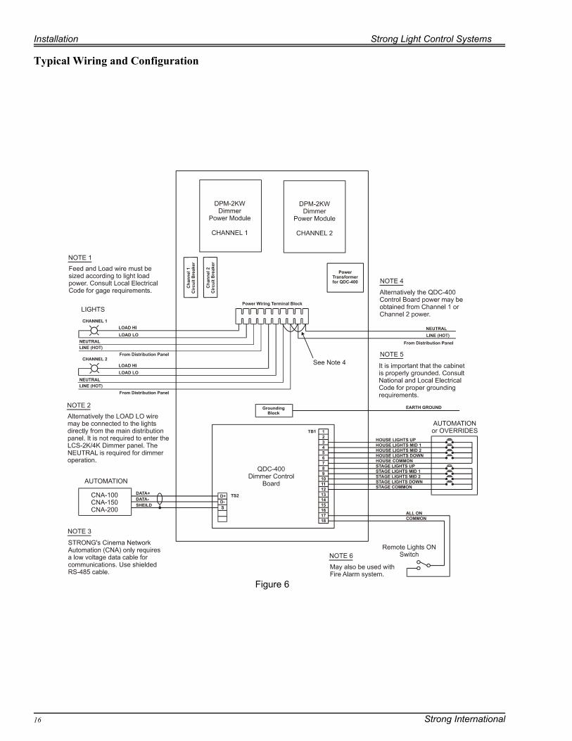
Typical Wiring and Configuration
Figure 6
Strong Light Control Systems Installation
Strong International 17
TAB1
L2L1
HI
LO
TB1
TAB4
DIM
MER
BOAR
D
TAB2
TAB3
37645
TRIA
C
GT
TB2
RF
CM
ACFeed
Incandescent LightsDo not exceed 2000 watts
per power module
Feed and Load wire gages must besized according to light load power.
House Lights
C.B.
Example 1
TAB1
L2L1
HI
LO
TB1
TAB4
DIM
MER
BO
AR
D
TAB2
TAB3
37645
TR
IAC
GT
TB2
RF
CM
ACFeed
Incandescent LightsDo not exceed 2000 watts
per power module
Feed and Load wire gages must besized according to light load power.
House Lights
C.B.
Example 2

Installation Strong Light Control Systems
Strong International18
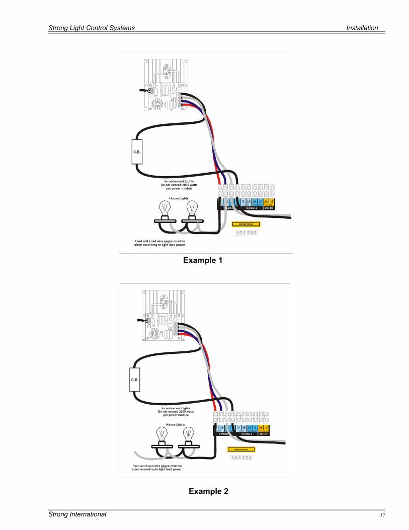
There are two acceptable methods of wiring the 2KW power modules found in the dimmer cabinet tothe lighting load. The first method involves wiring the return or neutral for the load and feed to thedimmer power module.The second method involves wiring the load return (neutral) to power distribution panel. A neutralconnection is still required at the power module. Since this wire will not carry much current, 18AWG wire is can be used.
The above diagrams are a general connection guide for installation, actual terminations will be madeat the terminal block within the cabinet. The load and line wiring is basically the same however.Much of the wiring is terminated internally and pre-wired during factory assembly.
The dimmer modules are mounted in a wall mount cabinet, hence you must determine theappropriate location for the unit. We recommend mounting it as close to the incoming power for thelights as possible. Power and signal/control lines may provide excellent conduction paths for rfi orelectrical noise and long unshielded wire may serve as an efficient antenna. By minimizing thedistance you are running the larger feed cables you are reducing the chance of erratic behavior. Youmay also want to consider keeping them at least six inches away from any audio cables andequipment since thyristor power or control lines may permit electrical noise to be induced into thesecables. Entering the cabinet, you should have an appropriately sized supply or feed line. The supplyline should be connected to the dimmer terminals identified as L1 (Hot, or Line) and L2 (Neutral) onthe appropriate circuit. This will depend on your particular cabinet’s configuration. The cabinetshould be properly grounded in accordance with local electrical code requirements. The load line forthe lights is connected to terminal positions identified as HI and LO once again corresponding to theappropriate circuit depending on unit configuration options.
All wiring connections should be secured in their locations and tested by gently pulling them toensure that they are firmly clamped in place. Inspect to be sure that the bare wire is contacting theterminal block contacts, and that the insulation is not interfering with conduction. Always double check your wiring for accuracy before applying power, damage as the result ofimproper connection will not be covered by your warranty. Additionally, the voltages and currentinvolved in this unit can be harmful or deadly if applied improperly.
Strong Light Control Systems Installation
Strong International 19
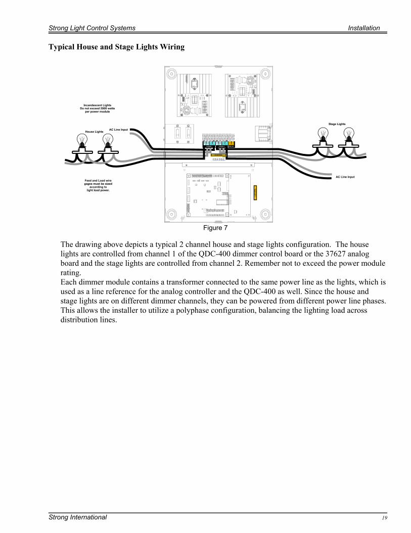
Typical House and Stage Lights Wiring
The drawing above depicts a typical 2 channel house and stage lights configuration. The houselights are controlled from channel 1 of the QDC-400 dimmer control board or the 37627 analogboard and the stage lights are controlled from channel 2. Remember not to exceed the power modulerating.Each dimmer module contains a transformer connected to the same power line as the lights, which isused as a line reference for the analog controller and the QDC-400 as well. Since the house andstage lights are on different dimmer channels, they can be powered from different power line phases.This allows the installer to utilize a polyphase configuration, balancing the lighting load acrossdistribution lines.
Figure 7
Installation Strong Light Control Systems
Strong International20
Figure 8
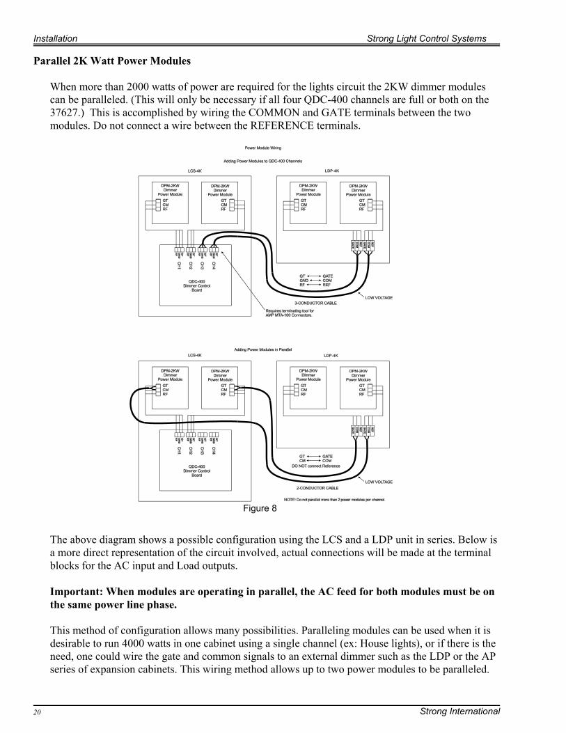
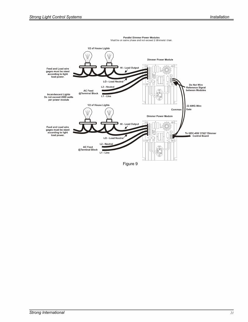
Parallel 2K Watt Power Modules
When more than 2000 watts of power are required for the lights circuit the 2KW dimmer modulescan be paralleled. (This will only be necessary if all four QDC-400 channels are full or both on the37627.) This is accomplished by wiring the COMMON and GATE terminals between the twomodules. Do not connect a wire between the REFERENCE terminals.
The above diagram shows a possible configuration using the LCS and a LDP unit in series. Below isa more direct representation of the circuit involved, actual connections will be made at the terminalblocks for the AC input and Load outputs.
Important: When modules are operating in parallel, the AC feed for both modules must be onthe same power line phase.
This method of configuration allows many possibilities. Paralleling modules can be used when it isdesirable to run 4000 watts in one cabinet using a single channel (ex: House lights), or if there is theneed, one could wire the gate and common signals to an external dimmer such as the LDP or the APseries of expansion cabinets. This wiring method allows up to two power modules to be paralleled.
Strong Light Control Systems Installation
Strong International 21
Figure 9
Installation Strong Light Control Systems
Strong International22
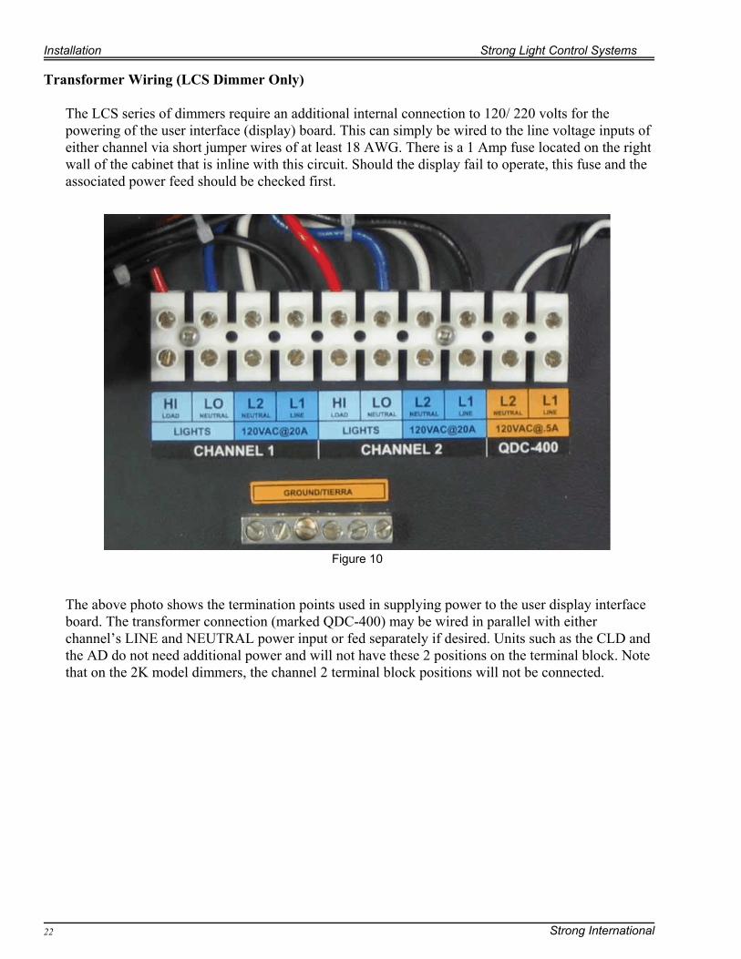
Transformer Wiring (LCS Dimmer Only)
The LCS series of dimmers require an additional internal connection to 120/ 220 volts for thepowering of the user interface (display) board. This can simply be wired to the line voltage inputs ofeither channel via short jumper wires of at least 18 AWG. There is a 1 Amp fuse located on the rightwall of the cabinet that is inline with this circuit. Should the display fail to operate, this fuse and theassociated power feed should be checked first.
The above photo shows the termination points used in supplying power to the user display interfaceboard. The transformer connection (marked QDC-400) may be wired in parallel with eitherchannel’s LINE and NEUTRAL power input or fed separately if desired. Units such as the CLD andthe AD do not need additional power and will not have these 2 positions on the terminal block. Notethat on the 2K model dimmers, the channel 2 terminal block positions will not be connected.
Figure 10
Strong Light Control Systems Installation
Strong International 23
CH4CH3CH2CH1
LINLIN LIN
GTGT
GTGT
GTGT
GTGT
CMCM
CMCM
CMCM
CMCM
RFRF
RFRF
RFRF
RFRF
HIHI
HIHI
HIHI
HIHI
LOLO
LOLO
LOLO
LOLO
L2L2
L2L2
L2L2
L2L2
L1L1
L1L1
L1L1
L1L1
CH4CH3CH2CH1
LINLIN LIN
GTGT
GTGT
GTGT
GTGT
CMCM
CMCM
CMCM
CMCM
RFRF
RFRF
RFRF
RFRF
HIHI
HIHI
HIHI
HIHI
LOLO
LOLO
LOLO
LOLO
L2L2
L2L2
L2L2
L2L2
L1L1
L1L1
L1L1
L1L1
GTGT
GTGT
GTGT
GTGT
CMCM
CMCM
CMCM
CMCM
RFRF
RFRF
RFRF
RFRF
DPM-2KW (x8)
DPM-2KW (x8) DPM-2KW (x8)
DPM-2KW (x8)
CH4CH3CH2CH1
LINLIN LIN
QDC-400 #1 QDC-400 #4
QDC-400 #2 QDC-400 #3
(LIN ID#13) (LIN ID#16)
(LIN ID#14) (LIN ID#15)
GTGT
GTGT
GTGT
GTGT
CMCM
CMCM
CMCM
CMCM
RFRF
RFRF
RFRF
RFRF
HIHI
HIHI
HIHI
HIHI
LOLO
LOLO
LOLO
LOLO
L2L2
L2L2
L2L2
L2L2
L1L1
L1L1
L1L1
L1L1
CH4CH3CH2CH1
LINLIN LIN
HIHI
HIHI
HIHI
HIHI
LOLO
LOLO
LOLO
LOLO
L2L2
L2L2
L2L2
L2L2
L1L1
L1L1
L1L1
L1L1
CHANNEL
4
CHANNEL
16
CHANNEL
8
CHANNEL
12
CHANNEL
3
CHANNEL
15
CHANNEL
7
CHANNEL
11
CHANNEL
2
CHANNEL
14
CHANNEL
6
CHANNEL
10
CHANNEL
1
CHANNEL
13
CHANNEL
5
CHANNEL
9
LIN
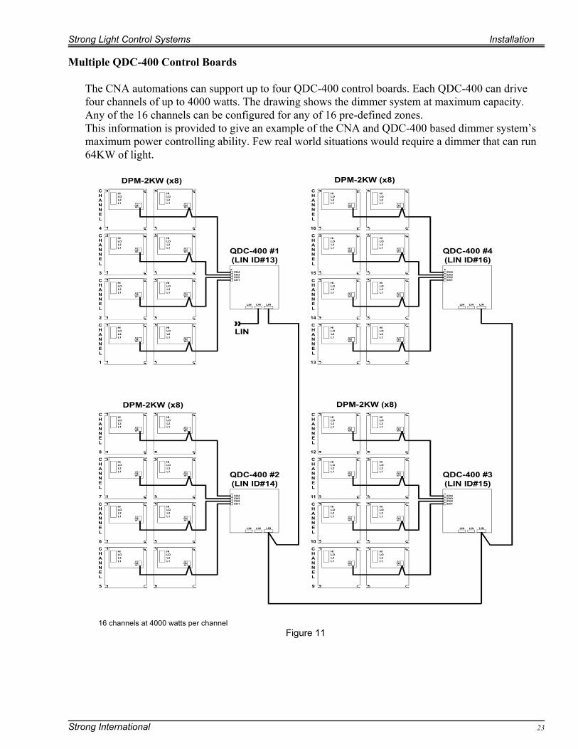
16 channels at 4000 watts per channelFigure 11
Multiple QDC-400 Control Boards
The CNA automations can support up to four QDC-400 control boards. Each QDC-400 can drivefour channels of up to 4000 watts. The drawing shows the dimmer system at maximum capacity.Any of the 16 channels can be configured for any of 16 pre-defined zones.This information is provided to give an example of the CNA and QDC-400 based dimmer system’smaximum power controlling ability. Few real world situations would require a dimmer that can run 64KW of light.
Setup Strong Light Control Systems
Strong International24
Figure 12
Setup
This section describes the setup and configuration of your dimmer. At this point you should have allof your load and line wiring completed. Procedures in this part of the manual will be used to setup,test, and verify that your unit operates. Both digital and analog dimmer controllers require theinstaller to do an initial setup where jumpers, switches and potentiometers are configured in ageneric fashion in order to get basic results that verify that everything is working as it should.
The QDC-400
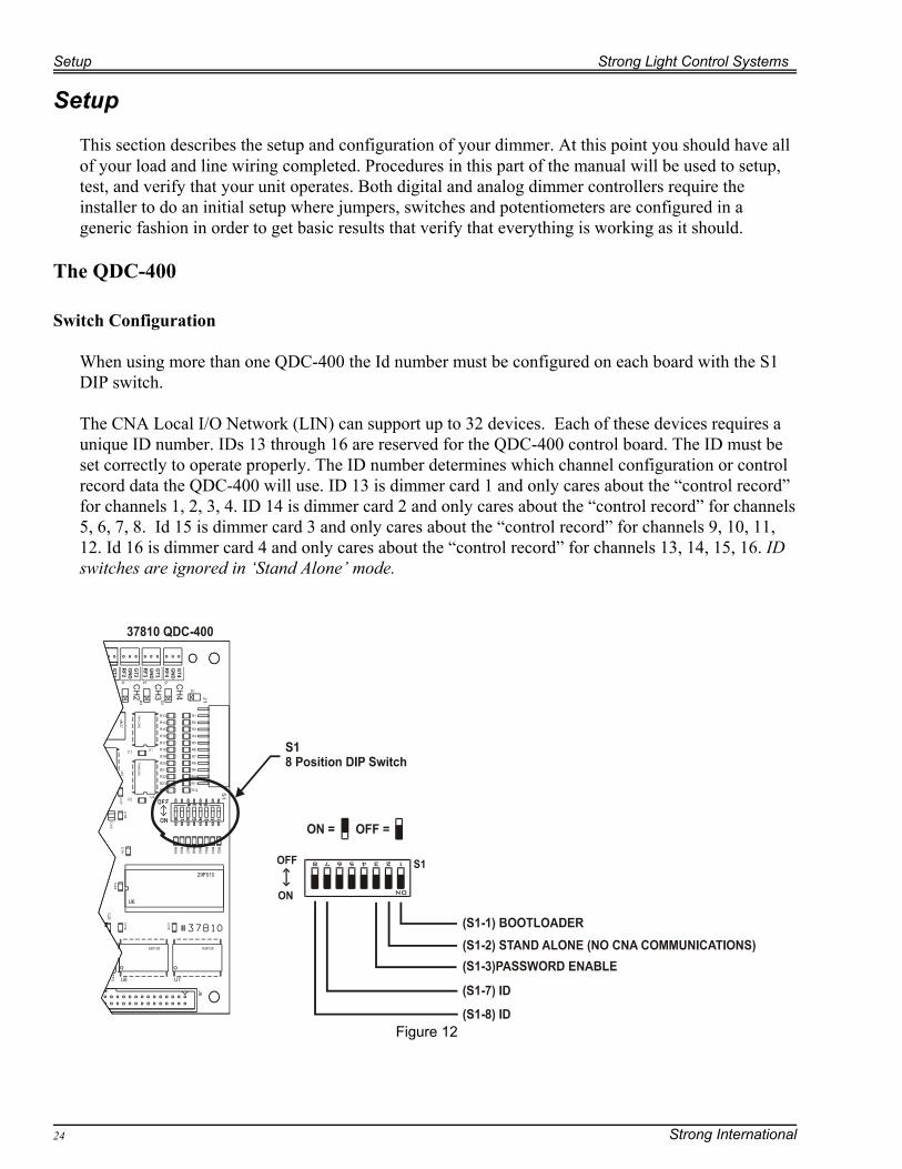
Switch Configuration
When using more than one QDC-400 the Id number must be configured on each board with the S1DIP switch.
The CNA Local I/O Network (LIN) can support up to 32 devices. Each of these devices requires aunique ID number. IDs 13 through 16 are reserved for the QDC-400 control board. The ID must beset correctly to operate properly. The ID number determines which channel configuration or controlrecord data the QDC-400 will use. ID 13 is dimmer card 1 and only cares about the “control record”for channels 1, 2, 3, 4. ID 14 is dimmer card 2 and only cares about the “control record” for channels5, 6, 7, 8. Id 15 is dimmer card 3 and only cares about the “control record” for channels 9, 10, 11,12. Id 16 is dimmer card 4 and only cares about the “control record” for channels 13, 14, 15, 16. IDswitches are ignored in ‘Stand Alone’ mode.
Strong Light Control Systems Setup
Strong International 25
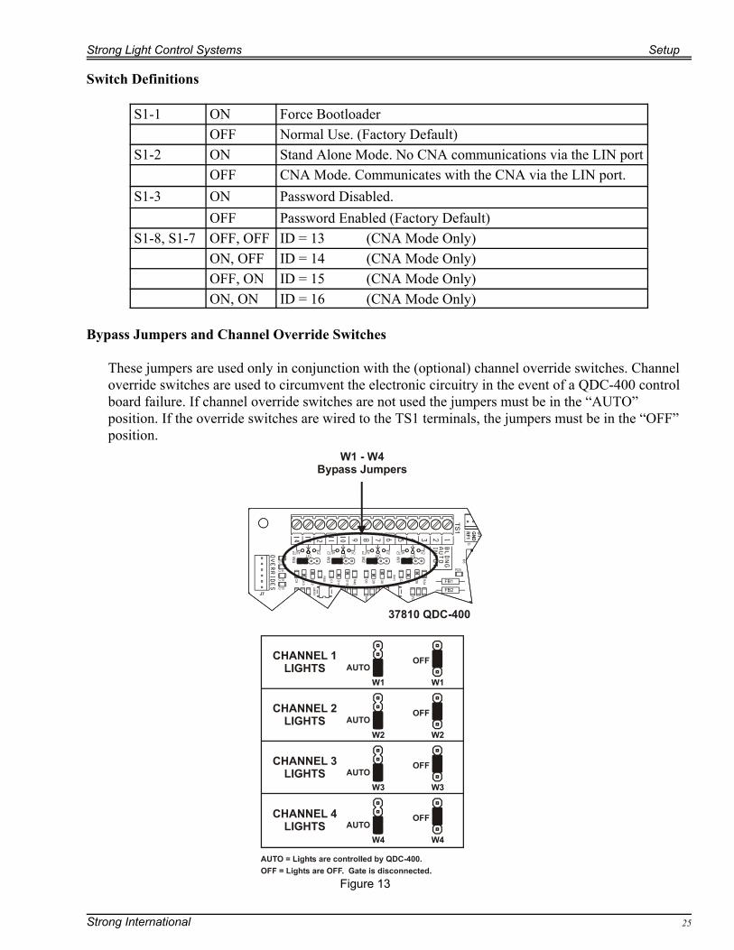
Figure 13
Switch Definitions
S1-1 ON Force BootloaderOFF Normal Use. (Factory Default)
S1-2 ON Stand Alone Mode. No CNA communications via the LIN portOFF CNA Mode. Communicates with the CNA via the LIN port.
S1-3 ON Password Disabled.OFF Password Enabled (Factory Default)
S1-8, S1-7 OFF, OFF ID = 13 (CNA Mode Only)ON, OFF ID = 14 (CNA Mode Only)OFF, ON ID = 15 (CNA Mode Only)ON, ON ID = 16 (CNA Mode Only)
Bypass Jumpers and Channel Override Switches
These jumpers are used only in conjunction with the (optional) channel override switches. Channeloverride switches are used to circumvent the electronic circuitry in the event of a QDC-400 controlboard failure. If channel override switches are not used the jumpers must be in the “AUTO”position. If the override switches are wired to the TS1 terminals, the jumpers must be in the “OFF”position.

Setup Strong Light Control Systems
Strong International26
The QDC-400 provides override inputs individual channel override. Each of channel can be wired toa "double-throw" switch allowing the manual control of the lights in the event of a board failure.
The channel override and cleaning lights switches are supplied by the user and should be mounted ina convenient location. The illustration below shows typical override connections.
D7
R39R36
C8
D1 R4
R87
R74
ULN2003A
U3
R97
68HC16U9
R68
R69
R67
R66
R90
TP1
C19L1
C17
R76
R73
FB2
VR1
LM2594-5
TS2
C31
R93
R13
U12
74HC240
R77
R81R78
R82
TP5TP4
R72
C36
S1
R89
R85
R75
R25
U7
6281
28
U6
29F0
10
4N37
ISO1
R9
R11
U1
74HC240
LM393
U4
C18
C22 C26
FB5
FB6
C20
C21
R71
R70
32.768KHZ
Y1
R22
R1
R2
R5
R8
R12
R60
R58
C15
C16
C2
C1
C32
C14
C33
C5
C34
MAX483
U13
TP3TP2
U8
6281
28
D12
Q4
MMBT3906LT1FB
1
R17
R18
R19
R33
R56
R57
R29
R26
R95
R96
C35
R98
FB4
D17
C30 L2
150UH
R94
D13R
15
R14
R83R79
C9 R61
R55
C7
R54
P2
R62
R88
R86
D10
Q3
MMBT3906LT1
Q1
MMBT3906LT1
C3
R16
R84
R6
R47
C11
C12
C13
C10
R48
R50
R32
R51R53
C6
R43
C38
C39
U11
MC34064P\SO
R63
R64
R65
D11
D8
Q2
MMBT3906LT1
R20
R21
R23
R24
R3
R10R7
U2
74HC240
R28
R49
R31
R46
R42
R41
D16
U10
X24C16
R92
R91
D9
D5
R80
R44
R27
R30
R40
P1
FB3
R100
C37
LED
1R
99
P3
D6
TS1
J7
R35R34
R37
C4
D15
Z2
Z1
W1
D4
U5
LM393
R59
R38
R45
D2
C28
D14
C25
C24
C23
C27
D3
W3
W2
W4
C29
C40
R52
J6J1
J5J4
J3J2
Channel 1Override
Channel 2Override
Channel 3Override
Channel 4Override
Use a single pole 3 position switch: On-Off-Auto. Where On is “lights full up”, Off is “lights full down” and Auto is “lights automatic”.
Use a single pole 2 position switch. On-Off. Where On is “lights full up” on all channels and Off is “lights normal”.
On
Auto
Off
CleaningLights
On
Normal
22 - 18 AWG3 conductor cable
Move jumpers W1-W4to center 2 pins for
override switches towork correctly. Factory wiring
Factory wiring
Figure 14
Strong Light Control Systems Setup
Strong International 27
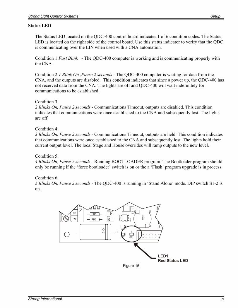
Figure 15
Status LED
The Status LED located on the QDC-400 control board indicates 1 of 6 condition codes. The StatusLED is located on the right side of the control board. Use this status indicator to verify that the QDCis communicating over the LIN when used with a CNA automation.
Condition 1:Fast Blink - The QDC-400 computer is working and is communicating properly withthe CNA.
Condition 2:1 Blink On ,Pause 2 seconds - The QDC-400 computer is waiting for data from theCNA, and the outputs are disabled. This condition indicates that since a power up, the QDC-400 hasnot received data from the CNA. The lights are off and QDC-400 will wait indefinitely forcommunications to be established.
Condition 3:2 Blinks On, Pause 2 seconds - Communications Timeout, outputs are disabled. This conditionindicates that communications were once established to the CNA and subsequently lost. The lightsare off.
Condition 4:3 Blinks On, Pause 2 seconds - Communications Timeout, outputs are held. This condition indicatesthat communications were once established to the CNA and subsequently lost. The lights hold theircurrent output level. The local Stage and House overrides will ramp outputs to the new level.
Condition 5: 4 Blinks On, Pause 2 seconds - Running BOOTLOADER program. The Bootloader program shouldonly be running if the ‘force bootloader’ switch is on or the a ‘Flash’ program upgrade is in process.
Condition 6: 5 Blinks On, Pause 2 seconds - The QDC-400 is running in ‘Stand Alone’ mode. DIP switch S1-2 ison.
Setup Strong Light Control Systems
Strong International28
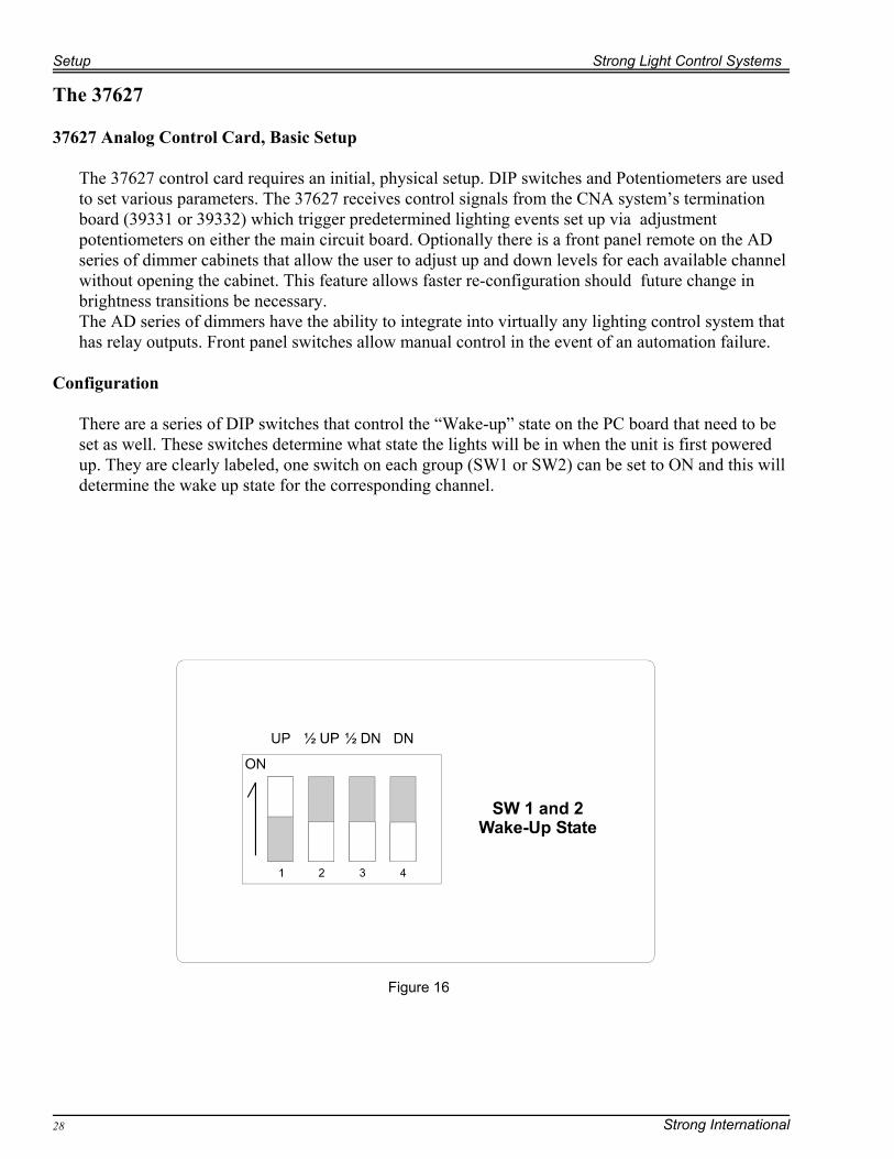
The 37627
37627 Analog Control Card, Basic Setup
The 37627 control card requires an initial, physical setup. DIP switches and Potentiometers are usedto set various parameters. The 37627 receives control signals from the CNA system’s terminationboard (39331 or 39332) which trigger predetermined lighting events set up via adjustmentpotentiometers on either the main circuit board. Optionally there is a front panel remote on the ADseries of dimmer cabinets that allow the user to adjust up and down levels for each available channelwithout opening the cabinet. This feature allows faster re-configuration should future change inbrightness transitions be necessary. The AD series of dimmers have the ability to integrate into virtually any lighting control system thathas relay outputs. Front panel switches allow manual control in the event of an automation failure.
Configuration
There are a series of DIP switches that control the “Wake-up” state on the PC board that need to beset as well. These switches determine what state the lights will be in when the unit is first poweredup. They are clearly labeled, one switch on each group (SW1 or SW2) can be set to ON and this willdetermine the wake up state for the corresponding channel.
Figure 16
Strong Light Control Systems Setup
Strong International 29
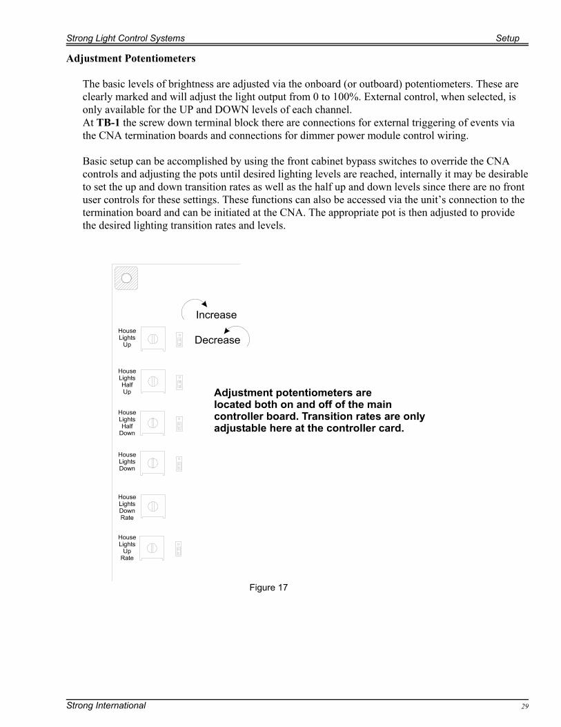
Adjustment Potentiometers
The basic levels of brightness are adjusted via the onboard (or outboard) potentiometers. These areclearly marked and will adjust the light output from 0 to 100%. External control, when selected, isonly available for the UP and DOWN levels of each channel. At TB-1 the screw down terminal block there are connections for external triggering of events viathe CNA termination boards and connections for dimmer power module control wiring.
Basic setup can be accomplished by using the front cabinet bypass switches to override the CNAcontrols and adjusting the pots until desired lighting levels are reached, internally it may be desirableto set the up and down transition rates as well as the half up and down levels since there are no frontuser controls for these settings. These functions can also be accessed via the unit’s connection to thetermination board and can be initiated at the CNA. The appropriate pot is then adjusted to providethe desired lighting transition rates and levels.
Figure 17

Setup Strong Light Control Systems
Strong International30
As shown in the accompanying illustrations, there are a series of potentiometers and jumpers on thecircuit board. The Jumpers control whether the dimmer adjustments are set on-board or whether theadjustments are set externally via P1. This P1 functionality is utilized when the 37627 board is in aAD controller. Set all jumpers to 2-3 (they will normally be configured this way when they leave thefactory). This enables external control.
Figure 18
Strong Light Control Systems Setup
Strong International 31
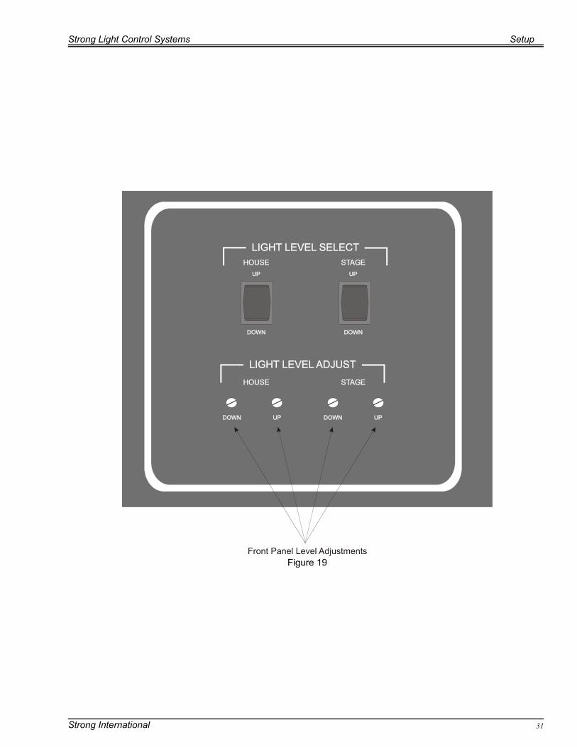
Figure 19
Setup Strong Light Control Systems
Strong International32
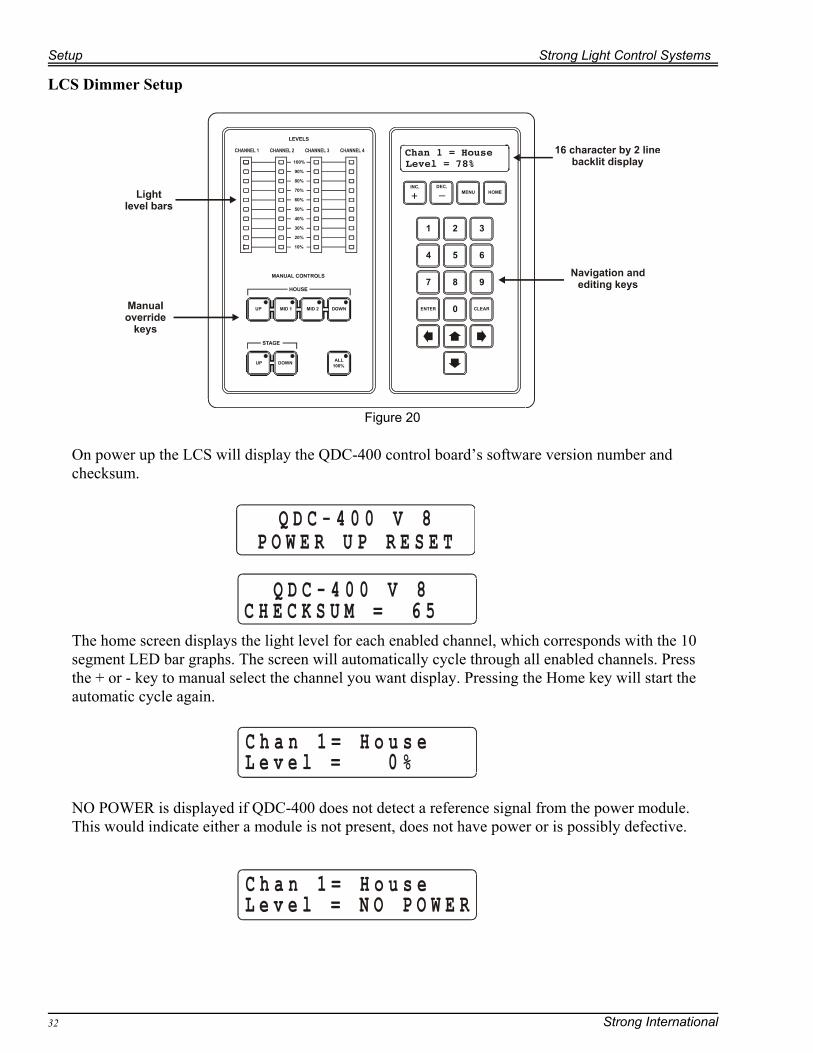
Figure 20
LCS Dimmer Setup
On power up the LCS will display the QDC-400 control board’s software version number andchecksum.
The home screen displays the light level for each enabled channel, which corresponds with the 10segment LED bar graphs. The screen will automatically cycle through all enabled channels. Pressthe + or - key to manual select the channel you want display. Pressing the Home key will start theautomatic cycle again.
NO POWER is displayed if QDC-400 does not detect a reference signal from the power module.This would indicate either a module is not present, does not have power or is possibly defective.
Strong Light Control Systems Setup
Strong International 33
To set-up the zones and levels for each channel, press [MENU][1]. Enter the password to gainaccess. Use the [=],[<],[>] or [?] keys to scroll to the field you want to edit. Select the desired zonefor each channel by pressing the [INC./+] or [DEC./-] keys and use the number keys to enter thelevel and fade time.
Note: Only the House and Stage zones are supported in Stand-alone mode. In order to use Zones 3through 16, the dimmer must be in CNA mode and connected to a CNA-200.
The QDC-400 can also display various status messages. To access these screens press [MENU][2].Press the [>] and [?] keys to scroll.
The QDC-400 supports the following five status messages:
QDC-400 V 8 This is the software version of the QDC-400 control board.
Checksum = 65 This is the software checksum
Board #1 Reflects the setting of the DIP switches S1-7 and S1-8Board #1 = ID 13Board #2 = ID 14Board #3 = ID 15Board #4 = ID 16
LIN Network:OFF
Reflects the setting of the DIP switch S1-2.OFF = Stand Alone ModeON = CNA Mode
Chan Ref: 1 2 _ _
Displays the channels that are receiving a reference signal fromthe dimmer power module.
Setup Strong Light Control Systems
Strong International34
Manual Control
Manual overrides are provided for both the House and Stage zones. The [All 100%] switch ramps allchannels to 100% in 2 seconds. Pushing the switch again ramps the lights back to the latest controllevel in two seconds.
Using the LCS-2K/4K Dimmer with the CNA
The LCS-2K/4K dimmer can be used with all CNA Automation systems. The dimmer’s QDC-400control board should be connected to the LIN. Dimmer data can be edited and saved both at theCNA and at the QDC-400. In order to synchronize the data, the following rules apply on how data issaved:
1. Both the QDC-400 and CNA are on and communicating and data is changed at the CNA.The data is transferred and saved to the QDC-400.
2. Both the QDC-400 and CNA are on and communicating and data is changed at the QDC-400. The data s transferred and saved to the CNA. The message TRANSFERRINGDATA TO CNA is displayed for 2 seconds to indicate a successful transfer.
3. The QDC-400 is off and the CNA is on. Data is changed at the CNA. The data istransferred and saved to the QDC-400 when it is powered on.
4. The QDC-400 is on and the CNA is off. Data is changed at the QDC-400. The messageTRANSFERRING DATA TO CNA is displayed followed by CAN’T CONNECT TOCNA. This message is displayed until a key is pressed or the CNA is powered on. Thedata is transferred and saved to the CNA when it is powered on and the messageTRANSFER TO CNA SUCCESSFUL is displayed. Press any key to clear the message.Note, however, that if the QDC-400 is powered off and then back on before the CNA ispowered on. The CNA will transfer and save it’s data to the QDC-400 overwriting theQDC-400 data.
5. Both the QDC-400 and CNA are powered up with changed data. The CNA wins. Data istransferred and saved to the QDC-400.
Setup Hint: The QDC-400 along with the DPM-2KW dimmer module can be used to extend bulblife. When set to the proper level, the dimmer can be used to preheat the lamp filaments at a pointjust below that required for incandescence. This makes it possible to avoid high initial currentsurges that result when power is first applied to an incandescent lamp because of the low resistanceof the cold filament. The high inrush current exposes the bulb filament to stress that can causepremature filament rupture.
eCNA-150 Dimmer Set-up
To access the QDC-400 dimmer setup menu screens:
From the main menu select: Set-Up (1), then choose Supervisory (1), Then select Dimmer (2) Enter your password if enabled, The Channel and Zone screen is the same as that of the CNA-150
Strong Light Control Systems Setup
Strong International 35
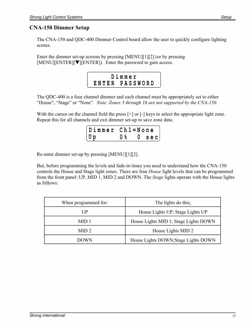
CNA-150 Dimmer Setup
The CNA-150 and QDC-400 Dimmer Control board allow the user to quickly configure lightingscenes.
Enter the dimmer set-up screens by pressing [MENU][1][2] (or by pressing[MENU][ENTER][–][ENTER]). Enter the password to gain access.
The QDC-400 is a four channel dimmer and each channel must be appropriately set to either“House”, “Stage” or “None”. Note: Zones 3 through 16 are not supported by the CNA-150.
With the cursor on the channel field the press [+] or [-] keys to select the appropriate light zone.Repeat this for all channels and exit dimmer set-up to save zone data.
Re-enter dimmer set-up by pressing [MENU][1][2].
But, before programming the levels and fade-in times you need to understand how the CNA-150controls the House and Stage light zones. There are four House light levels that can be programmedfrom the front panel: UP, MID 1, MID 2 and DOWN. The Stage lights operate with the House lightsas follows:
When programmed for: The lights do this:
UP House Lights UP; Stage Lights UP
MID 1 House Lights MID 1; Stage Lights DOWN
MID 2 House Lights MID 2
DOWN House Lights DOWN;Stage Lights DOWN
Setup Strong Light Control Systems
Strong International36
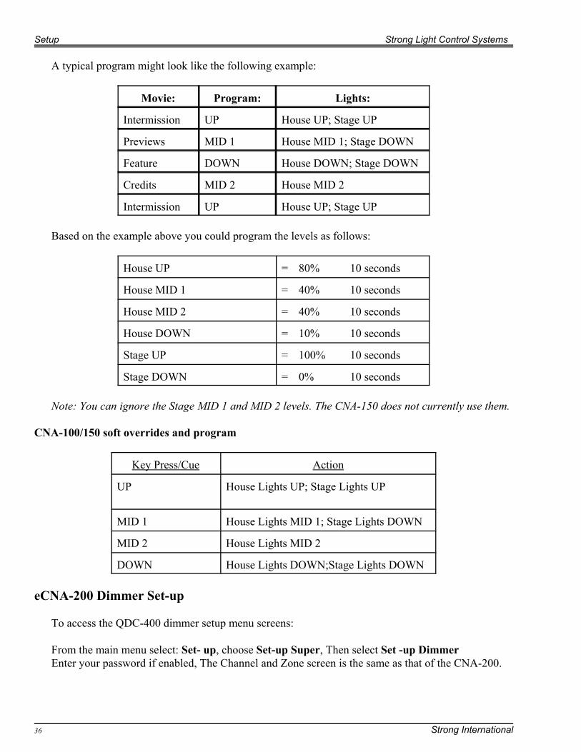
A typical program might look like the following example:
Movie: Program: Lights:
Intermission UP House UP; Stage UP
Previews MID 1 House MID 1; Stage DOWN
Feature DOWN House DOWN; Stage DOWN
Credits MID 2 House MID 2
Intermission UP House UP; Stage UP
Based on the example above you could program the levels as follows:
House UP = 80% 10 seconds
House MID 1 = 40% 10 seconds
House MID 2 = 40% 10 seconds
House DOWN = 10% 10 seconds
Stage UP = 100% 10 seconds
Stage DOWN = 0% 10 seconds
Note: You can ignore the Stage MID 1 and MID 2 levels. The CNA-150 does not currently use them.
CNA-100/150 soft overrides and program
Key Press/Cue Action
UP House Lights UP; Stage Lights UP
MID 1 House Lights MID 1; Stage Lights DOWN
MID 2 House Lights MID 2
DOWN House Lights DOWN;Stage Lights DOWN
eCNA-200 Dimmer Set-up
To access the QDC-400 dimmer setup menu screens:
From the main menu select: Set- up, choose Set-up Super, Then select Set -up DimmerEnter your password if enabled, The Channel and Zone screen is the same as that of the CNA-200.
Strong Light Control Systems Setup
Strong International 37
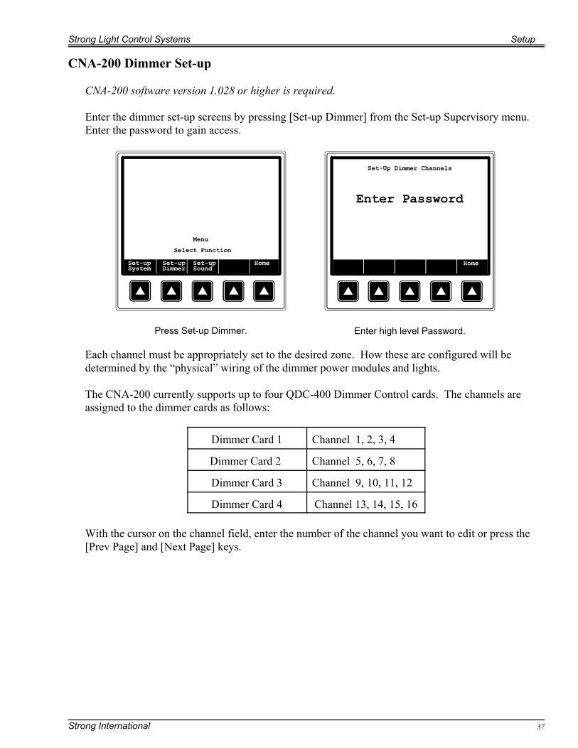
Enter high level Password.Press Set-up Dimmer.
CNA-200 Dimmer Set-up
CNA-200 software version 1.028 or higher is required.
Enter the dimmer set-up screens by pressing [Set-up Dimmer] from the Set-up Supervisory menu.Enter the password to gain access.
Each channel must be appropriately set to the desired zone. How these are configured will bedetermined by the “physical” wiring of the dimmer power modules and lights.
The CNA-200 currently supports up to four QDC-400 Dimmer Control cards. The channels areassigned to the dimmer cards as follows:
Dimmer Card 1 Channel 1, 2, 3, 4
Dimmer Card 2 Channel 5, 6, 7, 8
Dimmer Card 3 Channel 9, 10, 11, 12
Dimmer Card 4 Channel 13, 14, 15, 16
With the cursor on the channel field, enter the number of the channel you want to edit or press the[Prev Page] and [Next Page] keys.
Setup Strong Light Control Systems
Strong International38
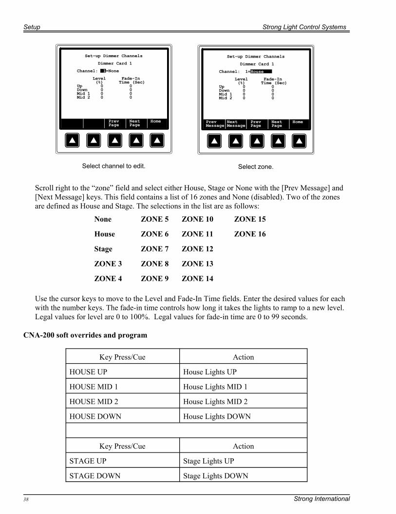
Select channel to edit. Select zone.
Scroll right to the “zone” field and select either House, Stage or None with the [Prev Message] and[Next Message] keys. This field contains a list of 16 zones and None (disabled). Two of the zonesare defined as House and Stage. The selections in the list are as follows:
None ZONE 5 ZONE 10 ZONE 15
House ZONE 6 ZONE 11 ZONE 16
Stage ZONE 7 ZONE 12
ZONE 3 ZONE 8 ZONE 13
ZONE 4 ZONE 9 ZONE 14
Use the cursor keys to move to the Level and Fade-In Time fields. Enter the desired values for eachwith the number keys. The fade-in time controls how long it takes the lights to ramp to a new level.Legal values for level are 0 to 100%. Legal values for fade-in time are 0 to 99 seconds.
CNA-200 soft overrides and program
Key Press/Cue Action
HOUSE UP House Lights UP
HOUSE MID 1 House Lights MID 1
HOUSE MID 2 House Lights MID 2
HOUSE DOWN House Lights DOWN
Key Press/Cue Action
STAGE UP Stage Lights UP
STAGE DOWN Stage Lights DOWN
Strong Light Control Systems Setup
Strong International 39
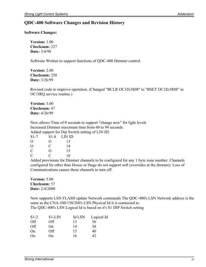
Host Version 1.007 Zone Names screen.
Host Dimmer Setup
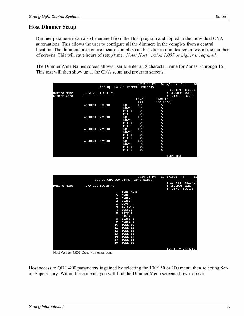
Dimmer parameters can also be entered from the Host program and copied to the individual CNAautomations. This allows the user to configure all the dimmers in the complex from a centrallocation. The dimmers in an entire theatre complex can be setup in minutes regardless of the numberof screens. This will save hours of setup time. Note: Host version 1.007 or higher is required.
The Dimmer Zone Names screen allows user to enter an 8 character name for Zones 3 through 16.This text will then show up at the CNA setup and program screens.
Host access to QDC-400 parameters is gained by selecting the 100/150 or 200 menu, then selecting Set-up Supervisory. Within these menus you will find the Dimmer Menu screens shown above.

Setup Strong Light Control Systems
Strong International40
A Photo showing the LCS Dimmer’s LCD display, here the output level is set at 71%. In theprevious section describing the QDC-400's operation a table is provided to indicate how muchvoltage is applied to the lighting load for a given percentage of maximum level.
Figure 21

Strong Light Control Systems Addendum
Strong International 41
Addendum
Troubleshooting
Care has been taken in the writing of this manual to make special note of potential problems that theinstaller can avoid. Rather than list all likely faults that can occur during testing, a functioning unitwill be defined for the purpose of analyzing and identifying a problem.
1) Power feed: Be sure power is connected to your unit. Check with a volt meter to see that voltageis present between the black and white wire terminations at the dimmer power module. Making surethat the breaker(s) are in the “ON” position you should have 120 or 220 Volts depending on yourmodel. If voltage is not present trace the power back to the terminal block, a meter should showvoltage between the recessed screws where the power feed enters the circuit. If there is no voltage atthe module, but there is voltage at the terminal block, suspect open wiring to the circuit breaker, onoccasion a circuit breaker will fail. The breaker can be removed and the continuity can be checkedwith your meter’s Ohms setting. If there is no voltage at the terminal block, suspect the input lines,either at the terminal block connection, or at your system’s feed circuit.Note: The LCS dimmer has a secondary power connection that supplies additional current to run thefront panel display circuitry. Check for proper line voltage at the terminal block positions for thisfeed. Observe and test if necessary the fuse located on the side wall of the unit.
The next item to check would be the load, with the power removed and your meter set to measureohms, check the resistance across the “Hi and Lo” terminals on the dimmer power module. Thereshould be a low resistance indicating that a load is present. If there is a high or infinite resistance,check the load connection at the terminal block, a low resistance should appear, if no resistance ismeasured, check your connections, there is an open circuit on the load side. If you measureresistance, there is an open between the terminal block and the power module.
In the event that there is proper voltage at the dimmer power modules and the load side circuit iscomplete, suspect the control circuitry.
2) Power module: After determining that your power modules have the proper voltage supply, wewill check the module circuitry. The easiest way to accomplish this would be to use the manualoverride switches, these typically bypass the programmable control circuitry altogether, thuseliminating the possibility of programming/ setup errors. Your unit’s problem then probably lieswithin the control board itself when the bypass switches do not function. In the case of a 4K unit thechannels are wired separate, if one works but the other doesn’t, the channels can be substituted andre-checked to see if the problem lies in the power module, or if it is confined to the controller.
3) Programming/ Setup: If your dimmer checks out fine up to this point the problem most likelylies within the automation or actuator that closes a contact. The analog controller responds to switchclosure, this can be manually checked with either a substitution or a measurement. Wire a switch toyour analog board’s input terminals (37627) then close the contacts. This should tell whether yourproblem lies in the 37627, or your termination board/ external control.The measurement method is accomplished by measuring a change from infinite to zero ohms whenyour external circuit is actuated (Note that the control board should not be connected to youractuator when using this method).

Addendum Strong Light Control Systems
Strong International42
The QDC dimmer can be checked by looking at the status indicator LED on the main board. If it isflashing rapidly, you have LIN communications with your automation. Network communication butno operation except when bypassed is a good indicator that programming or setup errors have beenmade. If there is no LIN communication, check your wiring etc...Check to see that the dimmer appears on the LIN if using a CNA automation or Host gatewayinterface. The LIN status screen should report a QDC, firmware version, and a net ID.
The above process can be adapted to the AP and LDP expansions, the primary difference of coursebeing that there is no control circuitry to check. The control cables should be verified to make surethat they are wired as specified in this manual.
If further help is required in troubleshooting, contact strong international.
Strong Light Control Systems Addendum
Strong International 43
QDC-400 Software Changes and Revision History
Software Changes:
Version: 1.00Checksum: 227Date: 3/4/98
Software Written to support functions of QDC-400 Dimmer control.
Version: 2.00 Checksum: 230
Date: 3/26/99
Revised code to improve operation. (Changed "BCLR OC1D,#$08" to "BSET OC1D,#$08" inOC1IRQ service routine.)
Version: 3.00 Checksum: 47Date: 4/26/99
Now allows Time of 0 seconds to support "change now" for light levelsIncreased Dimmer maximum time from 60 to 99 seconds.Added support for Dip Switch setting of LIN ID:S1-7 S1-8 LIN IDO O 13O C 14C O 15C C 16Added provisions for Dimmer channels to be configured for any 1 byte zone number. Channelsconfigured for other than House or Stage do not support soft (overrides at the dimmer). Loss ofCommunications causes these channels to turn off.
Version: 5.00Checksum: 57 Date: 2/4/2000
Now supports LSN FLASH update Network commands The QDC-400's LSN Network address is thesame as the CNA-100/150/200's LSN Physical Id it is connected to.The QDC-400's LSN Logical Id is based on it's S1 DIP Switch setting
S1-2 S1-LIN Id LSN Logical IdOff Off 13 36Off On 14 38On Off 15 40On On 16 42

Addendum Strong Light Control Systems
Strong International44
Version: 6.00Date: 6/6/2000
When Running this Bootloader program, the CNA-150/200 and Host programs will show "DevErr"or "Wrong Device Type" on the LIN Network Status Screen. Also when switching betweenBootloader and Application programs the CNA-150/200 may experience a LIN CommunicationsFault (Since the communications are interrupted for a brief period). Asserting the Fault depends onthe number of devices connected and the length of time it takes to the QDC-400 to switch programs. These messages and faults are normal and can (may) be expected when running the Bootloader
Version: 8AChecksum: 77Date: 4/22/04
Improved noise immunity and made unit operate better with 50 Hz power line frequencyDimmer screen now displays “transfer to CNA failed” message for 2 seconds rather than waiting fora second key to be depressed
BootLoader Changes:
Version: 001Checksum: 20Date: 2/4/2000
Created Bootloader Program for the QDC-400
Version: 002Checksum: 147Date: 5/9/2000
Increased rate at which watchdog is toggledNow Toggles watchdog in FL_Progbk routine
Version: 003Checksum: 221Date: 10/7/2002
Re-wrote FL_Erase routine, this allows full erasure of lettered AMD flash chipsets.
Version: 004Checksum: 208Date: 10/9/2003
Added support for front panel interface.
Strong International 45
Index:
37627 . . . . . . . . . . . . . . . . . . . . . . . . . . . . . . . . . . . . . . . . . . . . . . . . . . . . . . . . . . . . . . . . . . . . . . 10, 28, 3037627 Analog Control Card, Basic Setup . . . . . . . . . . . . . . . . . . . . . . . . . . . . . . . . . . . . . . . . . . . . . . . . 2437627 Operation: . . . . . . . . . . . . . . . . . . . . . . . . . . . . . . . . . . . . . . . . . . . . . . . . . . . . . . . . . . . . . . . . . . . 3937670 . . . . . . . . . . . . . . . . . . . . . . . . . . . . . . . . . . . . . . . . . . . . . . . . . . . . . . . . . . . . . . . . . . . . . . . . . . . . 1039331 . . . . . . . . . . . . . . . . . . . . . . . . . . . . . . . . . . . . . . . . . . . . . . . . . . . . . . . . . . . . . . . . . . . . . . . . . 10, 2839332 . . . . . . . . . . . . . . . . . . . . . . . . . . . . . . . . . . . . . . . . . . . . . . . . . . . . . . . . . . . . . . . . . . . . . . . 5, 10, 28Balancing the lighting load across phases . . . . . . . . . . . . . . . . . . . . . . . . . . . . . . . . . . . . . . . . . . . . . . . . 19Bypass Jumpers . . . . . . . . . . . . . . . . . . . . . . . . . . . . . . . . . . . . . . . . . . . . . . . . . . . . . . . . . . . . . . . . . . . . 25Channel override and cleaning lights switches . . . . . . . . . . . . . . . . . . . . . . . . . . . . . . . . . . . . . . . . . . . . 26CLD-2K . . . . . . . . . . . . . . . . . . . . . . . . . . . . . . . . . . . . . . . . . . . . . . . . . . . . . . . . . . . . . . . . . . . . . . . . . . . 5CLD-4K . . . . . . . . . . . . . . . . . . . . . . . . . . . . . . . . . . . . . . . . . . . . . . . . . . . . . . . . . . . . . . . . . . . . . . . . . . . 5CNA Mode . . . . . . . . . . . . . . . . . . . . . . . . . . . . . . . . . . . . . . . . . . . . . . . . . . . . . . . . . . . . . . . . . . . . . . . . 25CNA-100/150 soft overrides . . . . . . . . . . . . . . . . . . . . . . . . . . . . . . . . . . . . . . . . . . . . . . . . . . . . . . . . . . 36CNA-150 Dimmer Setup . . . . . . . . . . . . . . . . . . . . . . . . . . . . . . . . . . . . . . . . . . . . . . . . . . . . . . . . . . . . . 35CNA-200 Dimmer Set up . . . . . . . . . . . . . . . . . . . . . . . . . . . . . . . . . . . . . . . . . . . . . . . . . . . . . . . . . . . . 37CNA-200 soft overrides and program; . . . . . . . . . . . . . . . . . . . . . . . . . . . . . . . . . . . . . . . . . . . . . . . . . . 40Description, QDC-400 . . . . . . . . . . . . . . . . . . . . . . . . . . . . . . . . . . . . . . . . . . . . . . . . . . . . . . . . . . . . . . . . 6DPM-2KW Dimmer Module . . . . . . . . . . . . . . . . . . . . . . . . . . . . . . . . . . . . . . . . . . . . . . . . . . . . . . . . . . 10Extend bulb life . . . . . . . . . . . . . . . . . . . . . . . . . . . . . . . . . . . . . . . . . . . . . . . . . . . . . . . . . . . . . . . . . . . . 34Feed Wiring . . . . . . . . . . . . . . . . . . . . . . . . . . . . . . . . . . . . . . . . . . . . . . . . . . . . . . . . . . . . . . . . . . . . . . . 13Force Bootloader . . . . . . . . . . . . . . . . . . . . . . . . . . . . . . . . . . . . . . . . . . . . . . . . . . . . . . . . . . . . . . . . . . . 25Good ground . . . . . . . . . . . . . . . . . . . . . . . . . . . . . . . . . . . . . . . . . . . . . . . . . . . . . . . . . . . . . . . . . . . . . . 12Guidelines, Installation . . . . . . . . . . . . . . . . . . . . . . . . . . . . . . . . . . . . . . . . . . . . . . . . . . . . . . . . . . . . . . 12Host Dimmer Setup . . . . . . . . . . . . . . . . . . . . . . . . . . . . . . . . . . . . . . . . . . . . . . . . . . . . . . . . . . . . . . . . . 39ID number . . . . . . . . . . . . . . . . . . . . . . . . . . . . . . . . . . . . . . . . . . . . . . . . . . . . . . . . . . . . . . . . . . . . . . . . 24Installation . . . . . . . . . . . . . . . . . . . . . . . . . . . . . . . . . . . . . . . . . . . . . . . . . . . . . . . . . . . . . . . . . . . . . . . . 12Installation Guidelines . . . . . . . . . . . . . . . . . . . . . . . . . . . . . . . . . . . . . . . . . . . . . . . . . . . . . . . . . . . . . . . 12LCS Dimmer Setup . . . . . . . . . . . . . . . . . . . . . . . . . . . . . . . . . . . . . . . . . . . . . . . . . . . . . . . . . . . . . . . . . 32LCS-2K . . . . . . . . . . . . . . . . . . . . . . . . . . . . . . . . . . . . . . . . . . . . . . . . . . . . . . . . . . . . . . . . . . . . . . . . . . . 5LCS-4K . . . . . . . . . . . . . . . . . . . . . . . . . . . . . . . . . . . . . . . . . . . . . . . . . . . . . . . . . . . . . . . . . . . . . . . . . . . 5LDP-2K . . . . . . . . . . . . . . . . . . . . . . . . . . . . . . . . . . . . . . . . . . . . . . . . . . . . . . . . . . . . . . . . . . . . . . . . . . . 5LDP-4K . . . . . . . . . . . . . . . . . . . . . . . . . . . . . . . . . . . . . . . . . . . . . . . . . . . . . . . . . . . . . . . . . . . . . . . . . . . 5LED bar graphs . . . . . . . . . . . . . . . . . . . . . . . . . . . . . . . . . . . . . . . . . . . . . . . . . . . . . . . . . . . . . . . . . . . . 32Load and Feed Wiring: . . . . . . . . . . . . . . . . . . . . . . . . . . . . . . . . . . . . . . . . . . . . . . . . . . . . . . . . . . . . . . 16Load wiring . . . . . . . . . . . . . . . . . . . . . . . . . . . . . . . . . . . . . . . . . . . . . . . . . . . . . . . . . . . . . . . . . . . . . . . 13Local I/O Network (LIN) . . . . . . . . . . . . . . . . . . . . . . . . . . . . . . . . . . . . . . . . . . . . . . . . . . . . . . . . . . . . . 24luminescence . . . . . . . . . . . . . . . . . . . . . . . . . . . . . . . . . . . . . . . . . . . . . . . . . . . . . . . . . . . . . . . . . . . . . . . 7Manual Control . . . . . . . . . . . . . . . . . . . . . . . . . . . . . . . . . . . . . . . . . . . . . . . . . . . . . . . . . . . . . . . . . . . . 34mounting . . . . . . . . . . . . . . . . . . . . . . . . . . . . . . . . . . . . . . . . . . . . . . . . . . . . . . . . . . . . . . . . . . . . . . . . . 18Multiple QDC-400 . . . . . . . . . . . . . . . . . . . . . . . . . . . . . . . . . . . . . . . . . . . . . . . . . . . . . . . . . . . . . . . . . . 24Normal Operation . . . . . . . . . . . . . . . . . . . . . . . . . . . . . . . . . . . . . . . . . . . . . . . . . . . . . . . . . . . . . . . . . . . 9Operation . . . . . . . . . . . . . . . . . . . . . . . . . . . . . . . . . . . . . . . . . . . . . . . . . . . . . . . . . . . . . . . . . . . . . . . . . . 6Operational parameters . . . . . . . . . . . . . . . . . . . . . . . . . . . . . . . . . . . . . . . . . . . . . . . . . . . . . . . . . . . . . . 39Override Switches . . . . . . . . . . . . . . . . . . . . . . . . . . . . . . . . . . . . . . . . . . . . . . . . . . . . . . . . . . . . . . . . . . 25Parallel 2KW Modules . . . . . . . . . . . . . . . . . . . . . . . . . . . . . . . . . . . . . . . . . . . . . . . . . . . . . . . . . . . . . . . 20Password Disabled . . . . . . . . . . . . . . . . . . . . . . . . . . . . . . . . . . . . . . . . . . . . . . . . . . . . . . . . . . . . . . . . . . 25Password Enabled . . . . . . . . . . . . . . . . . . . . . . . . . . . . . . . . . . . . . . . . . . . . . . . . . . . . . . . . . . . . . . . . . . 25Potentiometers . . . . . . . . . . . . . . . . . . . . . . . . . . . . . . . . . . . . . . . . . . . . . . . . . . . . . . . . . . . . . . . . . . . . . 30

Strong International46
Power up defaults . . . . . . . . . . . . . . . . . . . . . . . . . . . . . . . . . . . . . . . . . . . . . . . . . . . . . . . . . . . . . . . . . . . 9QDC Configuration . . . . . . . . . . . . . . . . . . . . . . . . . . . . . . . . . . . . . . . . . . . . . . . . . . . . . . . . . . . . . . . . . 24QDC Operation . . . . . . . . . . . . . . . . . . . . . . . . . . . . . . . . . . . . . . . . . . . . . . . . . . . . . . . . . . . . . . . . . . . . 40QDC-400 Dimmer Controller . . . . . . . . . . . . . . . . . . . . . . . . . . . . . . . . . . . . . . . . . . . . . . . . . . . . . . . . . . 6AD-2K . . . . . . . . . . . . . . . . . . . . . . . . . . . . . . . . . . . . . . . . . . . . . . . . . . . . . . . . . . . . . . . . . . . . . . . . . . . . 5AD-4K . . . . . . . . . . . . . . . . . . . . . . . . . . . . . . . . . . . . . . . . . . . . . . . . . . . . . . . . . . . . . . . . . . . . . . . . . . . . 5AP-2K . . . . . . . . . . . . . . . . . . . . . . . . . . . . . . . . . . . . . . . . . . . . . . . . . . . . . . . . . . . . . . . . . . . . . . . . . . . . 5AP-4K . . . . . . . . . . . . . . . . . . . . . . . . . . . . . . . . . . . . . . . . . . . . . . . . . . . . . . . . . . . . . . . . . . . . . . . . . . . . 5Software Changes . . . . . . . . . . . . . . . . . . . . . . . . . . . . . . . . . . . . . . . . . . . . . . . . . . . . . . . . . . . . . . . . . . 43Square Law dimming curve . . . . . . . . . . . . . . . . . . . . . . . . . . . . . . . . . . . . . . . . . . . . . . . . . . . . . . . . . . . 7Stand Alone Mode . . . . . . . . . . . . . . . . . . . . . . . . . . . . . . . . . . . . . . . . . . . . . . . . . . . . . . . . . . . . . . . . . . 25Status LED . . . . . . . . . . . . . . . . . . . . . . . . . . . . . . . . . . . . . . . . . . . . . . . . . . . . . . . . . . . . . . . . . . . . . . . . 27Status messages . . . . . . . . . . . . . . . . . . . . . . . . . . . . . . . . . . . . . . . . . . . . . . . . . . . . . . . . . . . . . . . . . . . . 33Switch Configuration: . . . . . . . . . . . . . . . . . . . . . . . . . . . . . . . . . . . . . . . . . . . . . . . . . . . . . . . . . . . . . . . 24Switch Definitions . . . . . . . . . . . . . . . . . . . . . . . . . . . . . . . . . . . . . . . . . . . . . . . . . . . . . . . . . . . . . . . . . . 25Transformer Wiring: . . . . . . . . . . . . . . . . . . . . . . . . . . . . . . . . . . . . . . . . . . . . . . . . . . . . . . . . . . . . . . . . 21Transition rates . . . . . . . . . . . . . . . . . . . . . . . . . . . . . . . . . . . . . . . . . . . . . . . . . . . . . . . . . . . . . . . . . . . . 29Typical House and Stage Lights Wiring . . . . . . . . . . . . . . . . . . . . . . . . . . . . . . . . . . . . . . . . . . . . . . . . . 19Typical Wiring Examples . . . . . . . . . . . . . . . . . . . . . . . . . . . . . . . . . . . . . . . . . . . . . . . . . . . . . . . . . . . . 19Using the LCS-2K/4K Dimmer with the CNA . . . . . . . . . . . . . . . . . . . . . . . . . . . . . . . . . . . . . . . . . . . . 34“Wake Up State” . . . . . . . . . . . . . . . . . . . . . . . . . . . . . . . . . . . . . . . . . . . . . . . . . . . . . . . . . . . . . . . . . . . 10
Strong International 47
Illustrations:
Figure 1 Square Law Chart Figure 12 QDC DIP switchesFigure 2 37870 Block Diagram Figure 13 QDC Jumper LocationsFigure 3 Dimmer Power Module Illustration Figure 14 QDC Override ConnectionsFigure 4 Small Chassis Dimmer Mounting Figure 15 QDC Status LEDFigure 5 Large Chassis Dimmer Mounting Figure 16 37627 Wake-Up DIP SwitchesFigure 6 Wiring Configurations Figure 17 37627 Jumper and Pot LocationsFigure 7 Typical House and Stage Wiring Figure 18 37627 IllustrationFigure 8 Auxiliary Cabinet Wiring Figure 19 AD Front Panel IllustrationFigure 9 Parallel Dimmer Modules Figure 20 LCS Dimmer IllustrationFigure 10 Terminal Block Connections Figure 21 LCS Dimmer Controls PhotoFigure 11 Multiple QDC Configuration
Strong International48
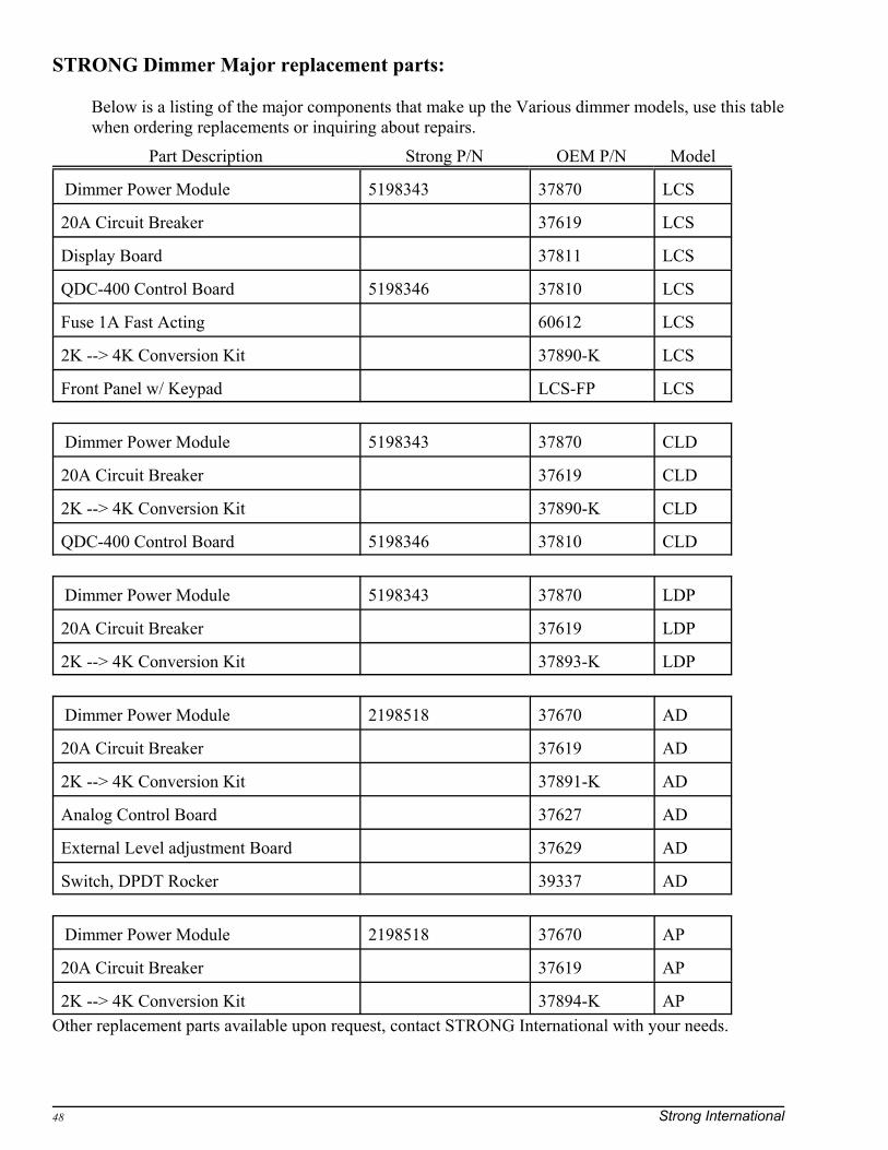
STRONG Dimmer Major replacement parts:
Below is a listing of the major components that make up the Various dimmer models, use this tablewhen ordering replacements or inquiring about repairs.
Part Description Strong P/N OEM P/N Model
Dimmer Power Module 5198343 37870 LCS
20A Circuit Breaker 37619 LCS
Display Board 37811 LCS
QDC-400 Control Board 5198346 37810 LCS
Fuse 1A Fast Acting 60612 LCS
2K --> 4K Conversion Kit 37890-K LCS
Front Panel w/ Keypad LCS-FP LCS
Dimmer Power Module 5198343 37870 CLD
20A Circuit Breaker 37619 CLD
2K --> 4K Conversion Kit 37890-K CLD
QDC-400 Control Board 5198346 37810 CLD
Dimmer Power Module 5198343 37870 LDP
20A Circuit Breaker 37619 LDP
2K --> 4K Conversion Kit 37893-K LDP
Dimmer Power Module 2198518 37670 AD
20A Circuit Breaker 37619 AD
2K --> 4K Conversion Kit 37891-K AD
Analog Control Board 37627 AD
External Level adjustment Board 37629 AD
Switch, DPDT Rocker 39337 AD
Dimmer Power Module 2198518 37670 AP
20A Circuit Breaker 37619 AP
2K --> 4K Conversion Kit 37894-K APOther replacement parts available upon request, contact STRONG International with your needs.

Installing the 3789x-K conversion kit: Rev. 5-1-06
4350 McKinley Street Omaha, Nebraska 68112 Tel 402/453-4444 Fax 402/453-7238 www.strong-cinema.com
a division of Ballantyne of Omaha, Inc.
Cinema ProductsCinema Products
IntroductionAll 2K version dimmers ship with only one dimmer power module and are capable of supporting up to 2,000 watts of incandescent lighting load. Some users may find it necessary to convert their single-channel 2K unit over to a dual-channel 4K unit or single channel 4K unit at a future date. This is usually for one of two reasons. Either the current configuration is not capable of handling the amount of lighting present in the auditorium due to an expansion or increase in lighting to be controlled, or the operator would like to have a second independent lighting channel.
Strong offers a convenient kit that will allow the user to install their own power module upgrade. These instructions are provided to guide the installer with this process. If you are not competent in working with electricity, please have a qualified electrician, technician, or other technically oriented person complete this process.
If a suitable installer cannot be found, the dimmer unit can be returned to Strong’s facility for upgrade and conversion.
The KitDepending on whether you have an analog or a digital dimmer your kit will contain either a 37670 or a 37870 dimmer power module, a high power wiring harness, a control cable assembly, a manual control switch and wiring(for the AD only), hardware, and a circuit breaker.
You will need this document, a phillips screw driver, a medium sized flat-blade screw driver, a 5/16 hex-head nut driver, and a small flat-blade screw driver. The procedure should take about 15 minutes but allow plenty of time in case of difficulty. You may wish to have a multi-meter or continuity tester on hand to test your wiring connections, however it is not required.

CautionAs stated earlier, if you are not competent working with electricity and hand tools, get someone who is to do the job. Power entering your dimmer’s cabinet must be completely disconnected before removal of the front panel. Merely switching off the front panel breakers will not disconnect anything but the dimmer power module from the incoming mains source.
The main breaker(s) that feed both the dimmer and the load must be locked out/ tagged so there is no chance of a mishap that could result in personal injury or property damage. The upgrade procedure is simple, safe and fast if all proper precautions are followed.
The Procedure Power must be completely removed and the work area prepared with tools and instructions handy loosen the 4 screws that hold the front panel to the main chassis. Your dimmer is probably wall mounted, so you will find the screws to the left and right sides. They are phillips/ hex head types, a nut driver can also be used, but you will need the screw driver later anyway. Once the screws are loosened, gently pull the cover out and detach the slide on connector at the chassis bottom. This is the safety ground wire that grounds the front panel, it MUST be installed during re-assembly.
Set the front panel aside where it will be out of your way. Next, look at the breaker mounting bracket located to the middle left of the cabinet, at the side of the unit you will see 2 screws. Remove them with your phillips screw driver and pull the bracket up and over toward the center of the unit. Don’t lose the screws.
Make a note of where the current circuit breaker is and how it is oriented in the bracket. Pry out the block off plate where the second circuit breaker is to be installed. You may find it easier to remove the existing breaker in order to get better access to the bracket. Once the plate is removed and the existing breaker re-installed (if removed), insert the new breaker assembly with attached wiring harness through the hole and insert and tighten mounting screws.
Circuit Breaker Assembly
#10 ExternalLock Washer
#10-32 Nut
LIN
E
LO
AD
#10-32 Nut
#10 Flat Washer
#10 Flat Washer
37821B High PowerDimmer Cable Assembly
* Should arrive pre-assembled
20A Circuit *Breaker
37814 BreakerMounting Bracket
#6-32 x 5/16"Phil Flat Undercut
Mach ScrewRemove block-off plate
*
*
*
*
*
*
Replace the breaker bracket and secure it with the two screws initially removed from the side of the cabinet. Route the 4 black circuit breaker wires through the notched area at the bottom of the bracket.The wiring harness will have three high power dimmer wires bundled with the black breaker wires.
Power module control wiring termination
High power wiring harness connections 37821B
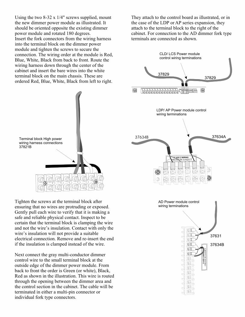
Using the two 8-32 x 1/4" screws supplied, mount the new dimmer power module as illustrated. It should be oriented opposite the existing dimmer power module and rotated 180 degrees.Insert the fork connectors from the wiring harness into the terminal block on the dimmer power module and tighten the screws to secure the connection. The wiring order at the module is Red, Blue, White, Black from back to front. Route the wiring harness down through the center of the cabinet and insert the bare wires into the white terminal block on the main chassis. These are ordered Red, Blue, White, Black from left to right.
Tighten the screws at the terminal block after ensuring that no wires are protruding or exposed. Gently pull each wire to verify that it is making a safe and reliable physical contact. Inspect to be certain that the terminal block is clamping the wire and not the wire’s insulation. Contact with only the wire’s insulation will not provide a suitable electrical connection. Remove and re-insert the end if the insulation is clamped instead of the wire.
Next connect the gray multi-conductor dimmer control wire to the small terminal block at the outside edge of the dimmer power module. From back to front the order is Green (or white), Black, Red as shown in the illustration. This wire is routed through the opening between the dimmer area and the control section in the cabinet. The cable will be terminated in either a multi-pin connector or individual fork type connectors.
They attach to the control board as illustrated, or in the case of the LDP or AP series expansion, they attach to the terminal block to the right of the cabinet. For connection to the AD dimmer fork type terminals are connected as shown.
CLD/ LCS Power module control wiring terminations
LDP/ AP Power module control wiring terminations
AD Power module control wiring terminations
Terminal block High power wiring harness connections 37821B
3782937829
37634A37634B
37631
37634B
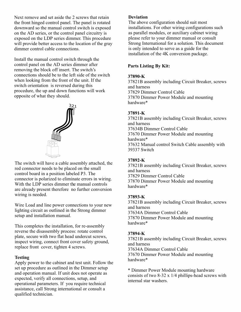
Next remove and set aside the 2 screws that retain the front hinged control panel. The panel is rotated downward so the manual control switch is exposed on the AD series, or the control panel circuitry is exposed on the LDP series dimmer. This procedure will provide better access to the location of the gray dimmer control cable connections.
Install the manual control switch through the control panel on the AD series dimmer after removing the block off insert. The switch’s connections should be to the left side of the switch when looking from the front of the unit. If the switch orientation is reversed during this procedure, the up and down functions will work opposite of what they should.
The switch will have a cable assembly attached, the red connector needs to be placed on the small control board in a position labeled P3. The connector is polarized to eliminate errors in wiring.With the LDP series dimmer the manual controls are already present therefore no further conversion wiring is needed.
Wire Load and line power connections to your new lighting circuit as outlined in the Strong dimmer setup and installation manual.
This completes the installation, for re-assembly reverse the disassembly process: rotate control plate, secure with two flat head undercut screws, inspect wiring, connect front cover safety ground, replace front cover, tighten 4 screws.
TestingApply power to the cabinet and test unit. Follow the set up procedure as outlined in the Dimmer setup and operation manual. If unit does not operate as expected, verify all connections, setup, and operational parameters. If you require technical assistance, call Strong international or consult a qualified technician.
DeviationThe above configuration should suit most installations. For other wiring configurations such as parallel modules, or auxiliary cabinet wiring please refer to your dimmer manual or consult Strong International for a solution. This document is only intended to serve as a guide for the installation of the 4K conversion package.
Parts Listing By Kit:
37890-K37821B assembly including Circuit Breaker, screws and harness37829 Dimmer Control Cable37870 Dimmer Power Module and mounting hardware*
37891-K37821B assembly including Circuit Breaker, screws and harness37634B Dimmer Control Cable37670 Dimmer Power Module and mounting hardware*37632 Manual control Switch Cable assembly with 39337 Switch
37892-K37821B assembly including Circuit Breaker, screws and harness37829 Dimmer Control Cable37870 Dimmer Power Module and mounting hardware*
37893-K37821B assembly including Circuit Breaker, screws and harness37634A Dimmer Control Cable37870 Dimmer Power Module and mounting hardware*
37894-K37821B assembly including Circuit Breaker, screws and harness37634A Dimmer Control Cable37670 Dimmer Power Module and mounting hardware*
* Dimmer Power Module mounting hardware consists of two 8-32 x 1/4 phillips-head screws with internal star washers.
321

Gray dimmerControl cable
Gray dimmerControl cable
High-power wiringharness with breaker
High-power wiringharness with breaker
Manual control switchwith harness
Breaker mtg.Bracket screws
Breaker mtg.Bracket screws
New circuitbreaker
New circuitbreaker
Dimmer powermodule
Dimmer powermodule
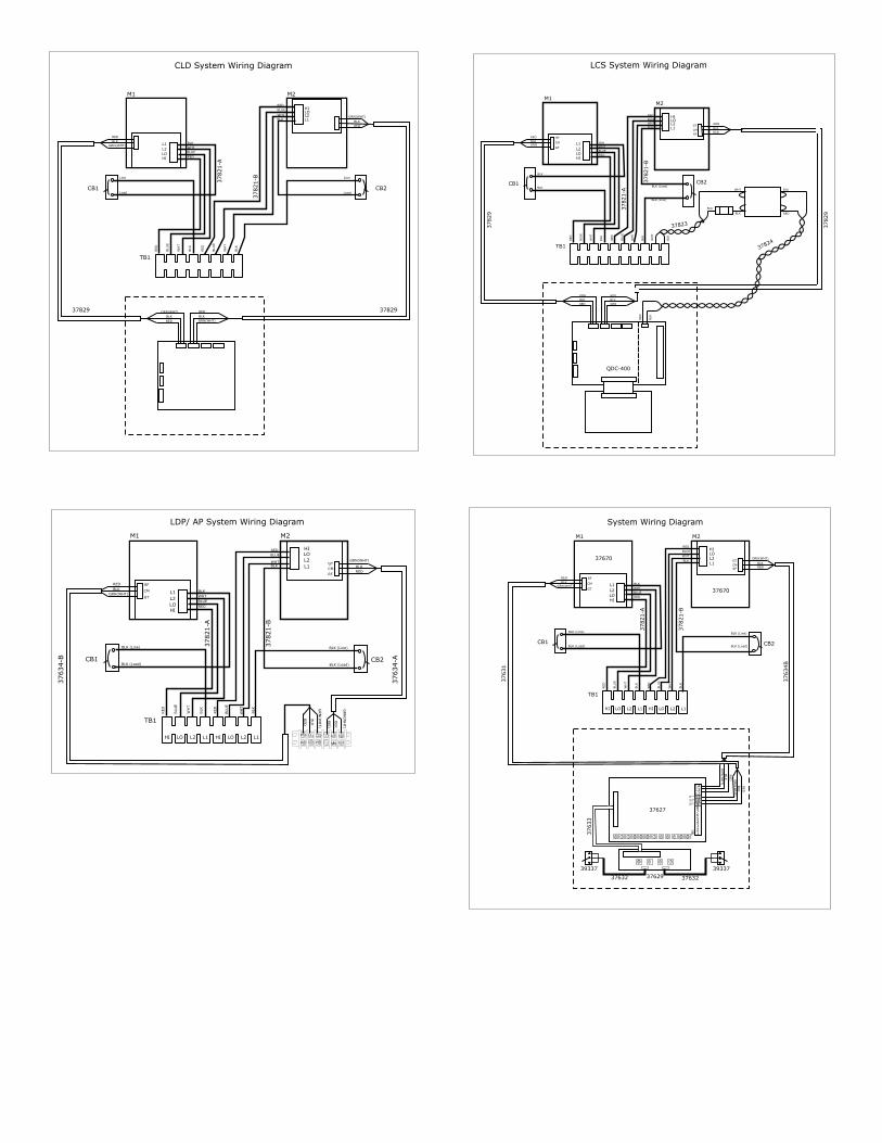
37870
GT
CM
RF
HILO
L2
L1
CLD System Wiring Diagram
M1 M2
37870
CB1 CB2
QDC-40037810
TB1
37829 37829
HI LO L2 L1 HI LO L2 L1
GT
CM
RF
GRN(WHT)
GRN(WHT)
HILO
L2
BLK
BLK
RED
RED
RED
RED
Line Line
Load Load
RED
RED
BLU
E
BLU
E
WH
T
WH
T
BLK
BLK
BLK
BLK
WHT
WHT
BLUE
BLUE
37821-A
37821-B
L1
CH
4
CH
3
CH
2
CH
1
LIN
LIN
LIN
GRN(WHT)
GRN(WHT)
BLK BLK
RED
RED
LCS System Wiring Diagram
M1M2
CB1 CB2
T1
QDC-40037810
37811-B
37811-A
37801
TB1
37829
37829
37823
37824
HI LO L2 L1 HI LO L2 L1 L2 L1
GT
GT
CM
CM
RF
RF
GRN
GRN
HIHI
HI
HI
LOLO
LO
LO
L2L2
L2
L2
BLK
BLK
RED
RED
RED
RED
BLK
BLK (Load)
BLK
BLK7
11
12
8RED
BLK
BLK
WH
T
WHTBLK
BLK (Line)
LINE
LINE
LOAD
LOAD
RED
RED
BLU
E
BLU
E
WH
T
WH
T
BLK
BLK
BLK
BLK
WHT
WHT
BLUE
BLUE
37821-A
37821-B
2
6
5
1
L1L1
L1
L1
F1
J5J4J3J2
P2
P1
P5
P4J1 TB1
J6
P3
TS2
GRN
GRN
BLK BLK
RED
RED
BLK
RED
M1 M2
CB1 CB2
TB1
HI LO L2 L1 HI LO L2 L1
GT
GT
CM
CM
RF
RF
GRN(WHT)
GRN(WHT)
HI
HI
LO
LO
L2
L2
BLK
BLK
RED
RED
RED
RED
BLK (Line) BLK (Line)
BLK (Load) BLK (Load)
RED
RED
BLU
E
BLU
E
WH
T
WH
T
BLK
BLK
BLK
BLK
WHT
WHT
BLUE
BLUE
37821-A
37821-B
37634-B
37634-A
L1
L1G
RN
(WH
T)
GRN
(WH
T)
BLK
BLK
RED
RED
LDP/ AP System Wiring Diagram
QDC-400
M1 M2
37670
37670
CB1 CB2
TB1
HI LO L2 L1 HI LO L2 L1
GT
GT
CM
CM
RF
RF
GRN(WHT)
GRN(WHT)
HI
HI
LO
LO
L2
L2
BLK
BLK
RED
RED
RED
RED
BLK (Line)BLK (Line)
BLK (Load) BLK (Load)
RED
RED
BLU
E
BLU
E
WH
T
WH
T
BLK
BLK
BLK
BLK
WHT
WHT
BLUE
BLUE
37821-A
37821-B
37631
37634B
37633
37632 37632
39337 39337
37629
L1
L1
GRN
(WH
T)
GRN
(WH
T)
BLK
BLK
RED
RED
System Wiring Diagram
37627
1234567891011121314
TB1
HouseRef
HouseCom
HouseGt