strongseam ag panel - metal panels inc
TRANSCRIPT
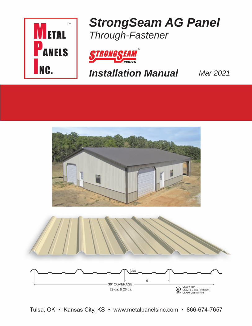
StrongSeam AG PanelThrough-Fastener
Installation Manual Mar 2021
Tulsa, OK • Kansas City, KS • www.metalpanelsinc.com • 866-674-7657
3/4
936” COVERAGE29 ga. & 26 ga.
UL90 #169UL2218 Class IV/ImpactUL790 Class A/Fire
2
Design
This manual contains guidelines for installing Metal Panels Inc. AG panels and trim. Guidelines presented herein were in effect as of this printing. Metal Panels Inc. reserves the right to change designs or specifications at any time in order to stay current with building code requirements. To ensure that you have the latest informa-tion, please contact your sales representative at Metal Panels Inc. Application and design illustrations are for your reference only, and may not be appropriate or speci-fied for all environments, conditions or building designs. It is strongly recommended that all projects should be engineered and installed to conform to applicable build-ing codes, regulations and accepted industry practices.
A roof must be designed to support certain minimum wind and snow loads. Consult local building officials to determine appropriate design load requirements. All roof systems should be designed or verified by a qualified engineer. It is the buyer’s responsibility to verify all code requirements, checking all measurements, and de-termine suitability of the product for the job. The buyer is responsible for supplying and confirming all panel and trim profiles, and actual length and quantities needed. All MPI instructions for this panel assume that a qualified firm or individual has been contracted to install this product. Failure to comply with stated recommendations voids all manufacturer responsibility for any damage or deterioration due to misuse of the product and voids any applicable warranty.
3
TABLE OF CONTENTSAG Panel Profile ………………………………………………………………………. 1
Design Guidelines ……………………………………………………………………. 2
Introduction to Installation ……………………………………………………………. 4
Storage & Handling …………………………………………………………………… 6
Design & Installation ………………………………………………………………….. 11
Standard Trim ………………………………………………………………………….. 13
Accessories ……………………………………………………………………………. 14
Preliminary Installation Guide ………………………………………………………… 15
Load Table ………………………………………………………………………………. 17
Roof Installation Options ……………………………………………………………… 18
Visual Guide: Drip …………………………………………………………………….. 20
Visual Guide: Rake …………………………………………………………………… 21
Visual Guide: Valley …………………………………………………………………… 22
Visual Guide: Ridge Cap ……………………………………………………………… 23
Visual Guide: Sidewall ………………………………………………………………… 24
Visual Guide: Endwall ………………………………………………………………… 25
Visual Guide: Gable Trim ……………………………………………………………... 26
Visual Guide: Pitch Change ………………………………………………………….. 27
Visual Guide: Peak Plate ……………………………………………………………… 28
Visual Guide: Inside Corner ………………………………………………………….. 29
Visual Guide: Fascia ………………………………………………………………….. 30
Visual Guide: Base ……………………………………………………………………. 31
Visual Guide: Rat Guard ……………………………………………………………… 32
Visual Guide: Soffit ……………………………………………………………………. 33
Visual Guide: Drip Cap ……………………………………………………………….. 34
Visual Guide: Double-Angle …………………………………………………………. 35
4
Introduction
The MPI StrongSeam AG Panel is a low-profile, economical panel solution for residential, commercial and agricultural roofing or post frame buildings. AG panels are a very durable, high-value metal roofing system, and can be used for roofing, siding, soffits, mansards and fascias. StrongSeam AG Panels are manufactured in 29 ga. and 26 ga., and are available in 16 stock colors plus galvalume in 29 ga., and 22 stock colors plus galvalume in 26 ga. (24 ga. panels available by special order.) Minimum recommended slope is 1:12 with sealant.
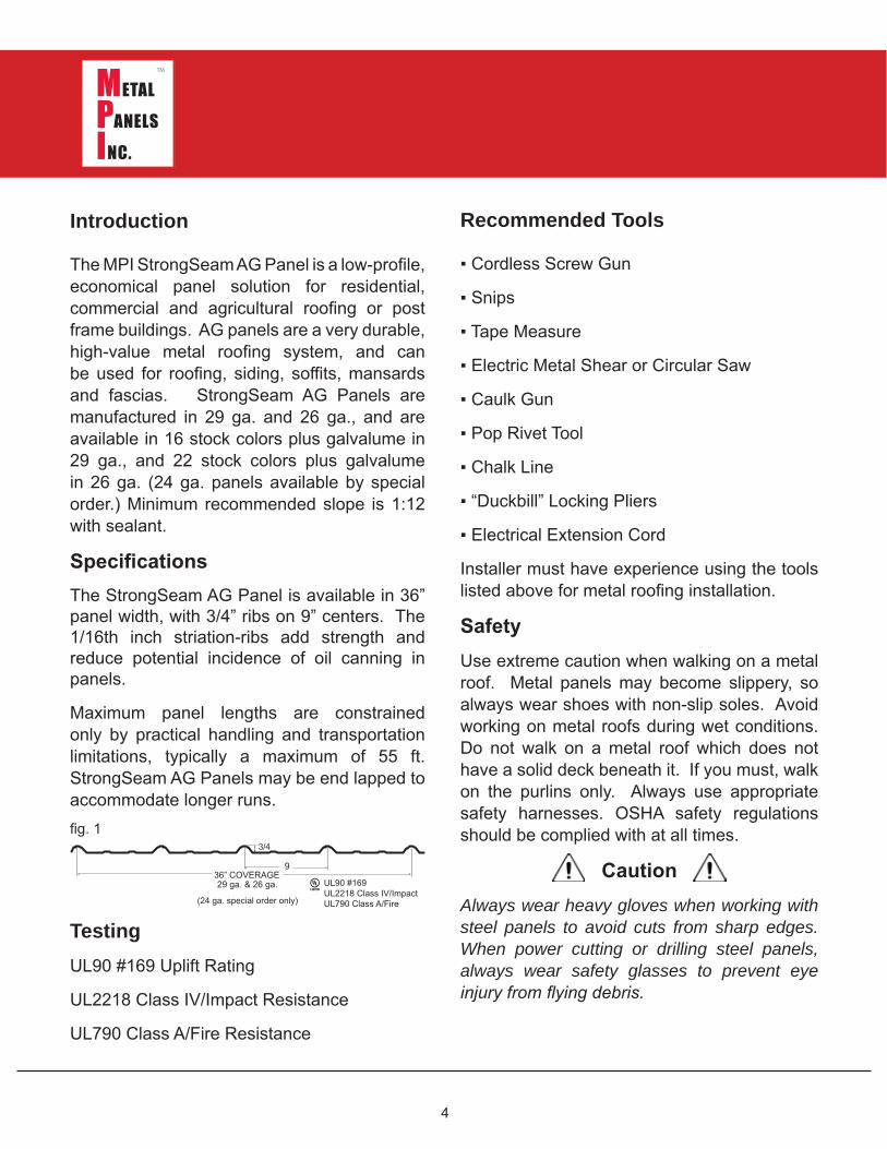
Specifications The StrongSeam AG Panel is available in 36” panel width, with 3/4” ribs on 9” centers. The 1/16th inch striation-ribs add strength and reduce potential incidence of oil canning in panels.
Maximum panel lengths are constrained only by practical handling and transportation limitations, typically a maximum of 55 ft. StrongSeam AG Panels may be end lapped to accommodate longer runs.
TestingUL90 #169 Uplift Rating
UL2218 Class IV/Impact Resistance
UL790 Class A/Fire Resistance
Recommended Tools
▪ Cordless Screw Gun
▪ Snips
▪ Tape Measure
▪ Electric Metal Shear or Circular Saw
▪ Caulk Gun
▪ Pop Rivet Tool
▪ Chalk Line
▪ “Duckbill” Locking Pliers
▪ Electrical Extension Cord
Installer must have experience using the tools listed above for metal roofing installation.
Safety Use extreme caution when walking on a metal roof. Metal panels may become slippery, so always wear shoes with non-slip soles. Avoid working on metal roofs during wet conditions. Do not walk on a metal roof which does not have a solid deck beneath it. If you must, walk on the purlins only. Always use appropriate safety harnesses. OSHA safety regulations should be complied with at all times.
Caution Always wear heavy gloves when working with steel panels to avoid cuts from sharp edges. When power cutting or drilling steel panels, always wear safety glasses to prevent eye injury from flying debris.
3/4
936” COVERAGE29 ga. & 26 ga. UL90 #169
UL2218 Class IV/ImpactUL790 Class A/Fire
fig. 1
(24 ga. special order only)
5
Production Lead Time
Please consult your MPI sales representative for accurate order production time. Large orders, non-standard colors, special order 24 ga. panels or custom trim fabrication may require longer lead times.
Packaging
For standard orders, panels are bundled for truck shipment. Custom shipping requirements may be accommodated at an additional charge.
6
Storage
If your metal panel order must be stored before use, store inside in a well-ventilated, dry location. Moisture from condensation can form between the sheets during storage causing water stains or white rust, which can damage the appearance of the panels and shorten the product’s useful life. To prevent moisture damage, break the shipping bands on the material and wipe dry any visible moisture on panels. Store the material on end or on a slight incline to promote water runoff. Support panels with a board underneath to prevent sagging. Allow for air circulation by spreading the sheets slightly at the bottom. Use wood blocks to keep the sheets off of the ground.
When metal panels will NOT to be used immediately, store inside in a well-ventilated, dry location. Outdoor storage is not recommended and may void warranties; to do so is at the customer’s own risk. Inspect the panels for moisture at the time of delivery. If moisture is present, the panels must be uncrated, wiped dry, and allowed to air-dry completely. Failure to remove trapped moisture between the sheets without delay may affect the appearance and longevity of the metal. Extended storage of bundled panels is not recommended. Panels must not be stored near or come in contact with salt water, corrosive chemicals, ash, solvent fumes, or come in contact with wet or green lumber.
STORAGE & HANDLING
If panel bundles must be stored outside, strictly adhere to these requirements:
1. Storage area should be level, and should be located to minimize handling of bundle during construction.
2. For storage on bare ground, place a plastic ground cover as a barrier under the bundle to minimize wicking moisture/condensation onto the panels from the soil.
3. Store bundle above the ground by a minimum of 6” to allow air circulation beneath the crate, and to prevent damage from rising water.
4. Raise one end of the crate slightly to permit runoff of moisture from the top of the bundle or from between nested panels. A water-resistant cover, like canvas should be placed over the bundle, with allowance for air circulation under the cover. Wood blocks should be used to raise the cover and provide air circulation between cover and crate.
5. Inspect stored bundle frequently and repair any tears or punctures in the water-resistant cover with a compatible waterproof tape.
6. Re-cover opened bundle at the end of each day to prevent entry of moisture and exposure to sunlight.
7
Protective Film Removal
Painted panels may have a protective film layer applied to the outside finish to prevent possible damage to the painted surface. Remove the protective film layer promptly, before exposing to direct sunlight and high temperatures. After exposure to heat or sunlight, the protective film cannot be removed. Never leave the protective film on the panels after installation. Metal Panels Inc. cannot be held liable for damage to metal caused by improper storage and failure to remove protective film.
Some Safety Precautions
To prevent injury, always wear heavy gloves when working with steel panels. Wear safety glasses when cutting or drilling steel panels, and remove any metal shavings immediately to reduce risk of eye injury from flying debris. Avoid walking on metal panels; If you must walk on a metal roof, use extreme caution. Wear shoes with non-slip soles, for metal panels can become slippery even dry. Avoid working on metal roofs during wet conditions when the panels can become extremely slick. Walking or standing on a metal roof which does not have a solid deck beneath it is not recommended. If unavoidable, always walk on the purlins, never between. Do not for any reason walk on a roof made of material thinner than 29 gauge
Roof Storage
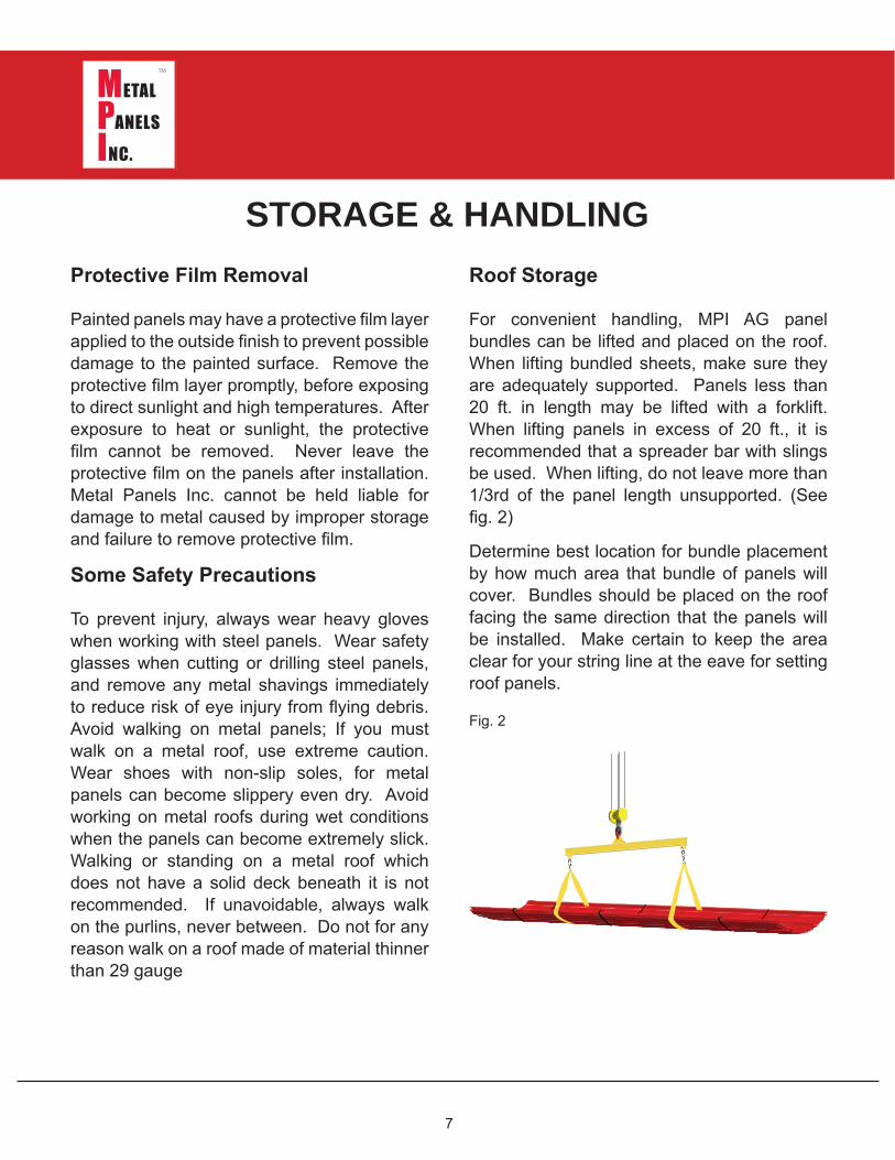
For convenient handling, MPI AG panel bundles can be lifted and placed on the roof. When lifting bundled sheets, make sure they are adequately supported. Panels less than 20 ft. in length may be lifted with a forklift. When lifting panels in excess of 20 ft., it is recommended that a spreader bar with slings be used. When lifting, do not leave more than 1/3rd of the panel length unsupported. (See fig. 2)
Determine best location for bundle placement by how much area that bundle of panels will cover. Bundles should be placed on the roof facing the same direction that the panels will be installed. Make certain to keep the area clear for your string line at the eave for setting roof panels.
Fig. 2
STORAGE & HANDLING
8
Receiving Materials
The installer has the responsibility to unload material from the delivery truck. The installer must provide suitable equipment for safely unloading all materials from the delivery truck. (MPI offers truck-mounted forklift deliveries for an additional charge.)
After receiving your order, verify the condition of the material and compare the shipment against the shipping list to ensure all ordered items have been received. If damages or shortages are discovered, note the discrepency on the shipping copy at time of delivery. If replacement material is required, you must contact Metal Panels Inc. to place the order. Report any damages or shortages to Metal Panels Inc. within 48 hours from the time of shipment.
Caution
Improper loading and unloading of bundle may result in bodily harm and/or material damage. Metal Panels Inc. is not responsible for bodily injuries and/or material damages resulting from improper loading or unloading.
General Handling
Each bundle should be handled with care to avoid product damage. Proper handling should be used to prevent bending panels or scratching the finish. To prevent panel damage, follow these steps for unloading and handling bundle:
STORAGE & HANDLING
1. Bundle should remain banded and intact during any handling and remain banded until the panels are ready to be installed. Never lift bundle by their banding.
2. Always lift bundle as close as possible to its center of gravity
3. When lifting by crane, use a spreader bar of appropriate length and nylon band slings. (DO NOT use cable slings; they will damage panels.)
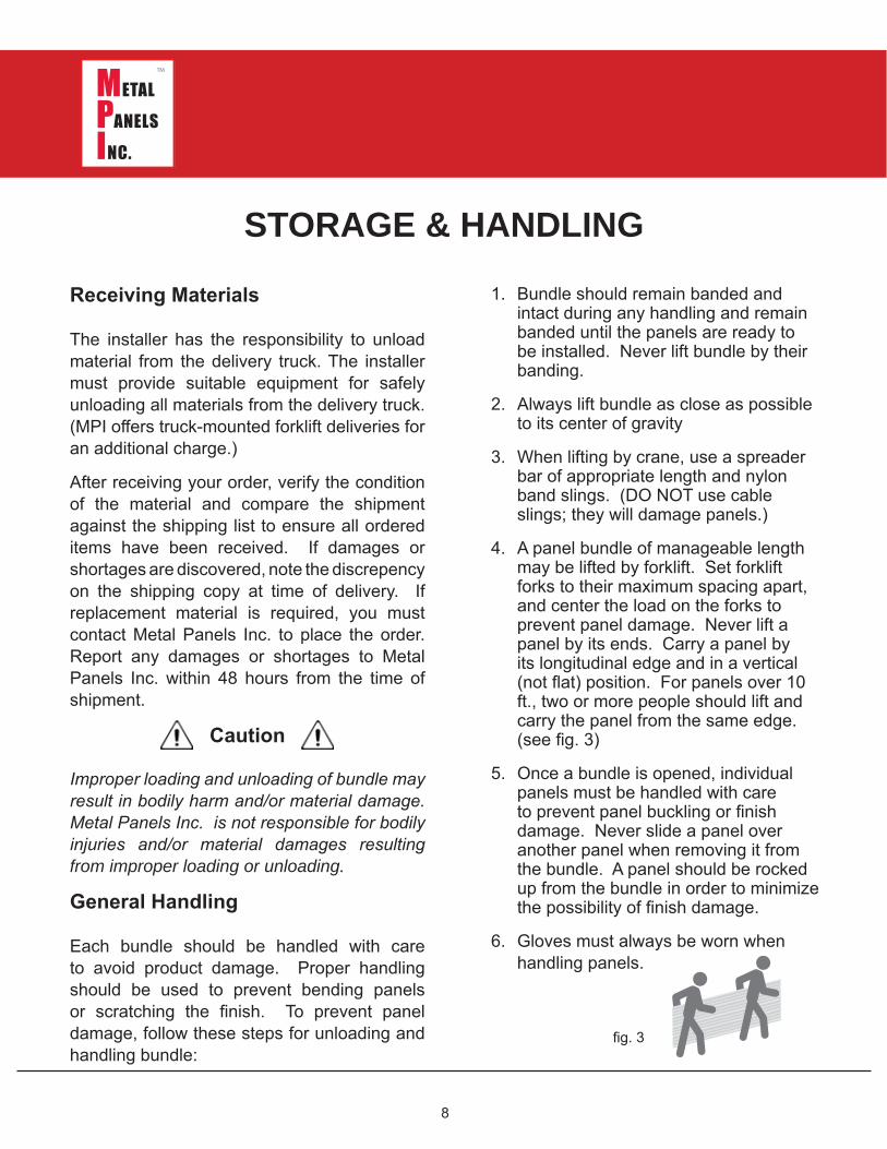
4. A panel bundle of manageable length may be lifted by forklift. Set forklift forks to their maximum spacing apart, and center the load on the forks to prevent panel damage. Never lift a panel by its ends. Carry a panel by its longitudinal edge and in a vertical (not flat) position. For panels over 10 ft., two or more people should lift and carry the panel from the same edge. (see fig. 3)
5. Once a bundle is opened, individual panels must be handled with care to prevent panel buckling or finish damage. Never slide a panel over another panel when removing it from the bundle. A panel should be rocked up from the bundle in order to minimize the possibility of finish damage.
6. Gloves must always be worn when handling panels.
fig. 3
9
Mechanical Handling
Using a Forklift
A forklift may be used for panels up to 20 ft. Set the forks at their maximum separation and center the load on the forks. When transporting bundle across rough terrain, or over a long distance, use nylon straps or similar means of additional support for the bundle. Never transport an open bundle.
Using a Crane
For lifting panel bundle greater than 20 ft. in length, a crane is recommended. Utilize an appropriate spreader bar to ensure even distribution of the weight to the lift points. No more than 1/3rd of the length of the panel should be left unsupported when lifting panel bundle. Canvas or nylon slings should be used to lift panels. DO NOT use cable or chains; they will damage the panels.
Foot Traffic
Walking on a metal roof can cause distortion of panels and damage to the finish. Foot traffic on an installed roof system must be kept to an absolute minimum. If continuous foot traffic is necessary for maintenance over the roof, then a permanent walkway should be installed.
For foot traffic during installation, provide walking platforms to avoid any panel damage.
If walking on the roof panels is unavoidable, walk only in the flats of the panel; walking on the ribs can damage the panels.
STORAGE & HANDLING
Metal roof installers must be in full compliance with all applicable safety regulations including OSHA regulations.
Field Cutting
Tin snips, a portable shear or a “nibbler” type electric tool are recommended for field cutting AG Panels. If a skill saw is used, the blade will generate shavings of metal chips. Some of the shavings may be hot enough to burn the paint down to the metal substrate. Any metal shavings must be immediately removed from the panel because they will damage the finish and induce rust staining or panel failure.
One approach to addressing this problem is to flip the panels over when cutting. The metal shavings can be brushed away from the back side, preventing finish damage to the top side of the panels.
All roof or panel surfaces must be free of debris at all times. Installed surfaces should be wiped clean at the end of each work day. Never cut panels over other metal surfaces. Metal shavings will rust on the surface which will void the warranty.
Always wear goggles for eye protection when cutting metal panels.
Caution
Caution
10
STORAGE & HANDLINGTouch-up Paint
All painted panels, trim and flashings have a factory-applied heat-cured finish. During handling and installation, a panel may become slightly scratched or nicked. Paint pens are available in matching colors. It is recommended to use the sharp edge of the chisel tip to apply touch-up paint only to those areas that are in need of repair (apply touch-up paint to the scratch itself. Do not paint over panel finish). Be aware that touch-up paint does not have the superior chalk and fade resistance of the factory-applied finish and will likely discolor at an accelerated rate. Periodic touch-up may be required to maintain color match. Due to the limitations and formulation of field-applied touch-up paint, there is no warranty offered for color match or durability of the product.
When touching up scratches in pan-els or flashing, it is VERY IMPORTANT not to over paint the area to be touched up. Because of the curing solvent which must be added, air-dry formula touch-up paint WEATHERS DIFFERENTLY than the thermoset formula paint which is applied on the coil coating line. For this reason, excessive strokes will create an unsightly appearance and will worsen over time, becoming aesthetically unacceptable.
Please see MPI’s Touchup Paint Flyer for complete instructions.
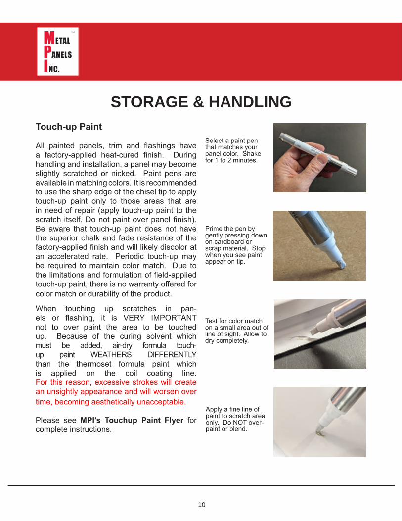
Select a paint pen that matches your panel color. Shake for 1 to 2 minutes.
Prime the pen by gently pressing down on cardboard or scrap material. Stop when you see paint appear on tip.
Test for color match on a small area out of line of sight. Allow to dry completely.
Apply a fine line of paint to scratch area only. Do NOT over-paint or blend.
11
Design & Installation Considerations
Insulation & Ventilation
Properly designed and installed vapor barriers and ventilation systems prevent condensation and the resulting moisture damage and loss of insulation efficiency.
When highly-humid air contacts building surfaces that are below the dew point temperature of the air, condensation will occur.
Proper insulation can provide resistance to heat transfer and protection against condensation forming on cooler surfaces within the building or the roof system.
The building designer is responsible to specify an appropriate vapor retarder and insulation system for the project.
DESIGN & INSTALLATION
Basic guidelines for control of condensation are as follows:
1. Faced insulation (insulation with vapor retarder) should be installed with the facing toward the warm side of the insulated area, typically, the interior of a building.
2. Insulation R-value must be high enough to maintain the temperatures of the vapor retarder above the interior dew point, using “worst-case” outside temperatures for a reference.
3. Seal all seams and penetrations of the vapor barrier in order to provide a continuous membrane to resist the passage of water vapor.
4. Structure ventilation contributes significantly to reducing condensation. Whether by passive or active (powered) venting, air movement to the outside of the building reduces interior vapor pressure.
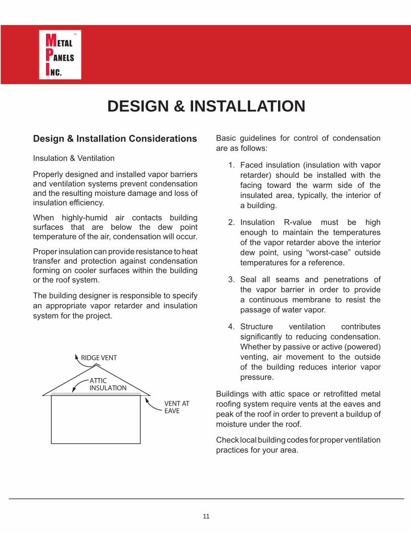
Buildings with attic space or retrofitted metal roofing system require vents at the eaves and peak of the roof in order to prevent a buildup of moisture under the roof.
Check local building codes for proper ventilation practices for your area.
VENT ATEAVE
ATTICINSULATION
RIDGE VENT
12
Roofing Substrates
In warm weather climates, Palisade synthetic underlayment should be used over the existing decking. The high temperature resistance prevents it from sticking to the panels and tearing, which can occur with asphalt-based felt paper.
In colder climates, ice and water shield should be used at the valley and eave. Apply over the decking before installation of the synthetic underlayment.
Use appropriate safety precautions when applying synthetic substrates because they can be slippery.
DESIGN & INSTALLATION
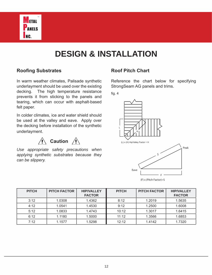
Roof Pitch Chart
Reference the chart below for specifying StrongSeam AG panels and trims.
Caution
PITCH PITCH FACTOR HIP/VALLEY FACTOR
PITCH PITCH FACTOR HIP/VALLEY FACTOR
3:12 1.0308 1.4362 8:12 1.2019 1.56354:12 1.0541 1.4530 9:12 1.2500 1.60085:12 1.0833 1.4743 10:12 1.3017 1.64156:12 1.1180 1.5000 11:12 1.3566 1.68537:12 1.1577 1.5298 12:12 1.4142 1.7320
L
H
(L) x (H) [Hip/Valley]
S
F
Peak
Eave
(F) x (Pitch Factor)=S
fig. 4
(L) x (H) Hip/Valley Factor = H
13
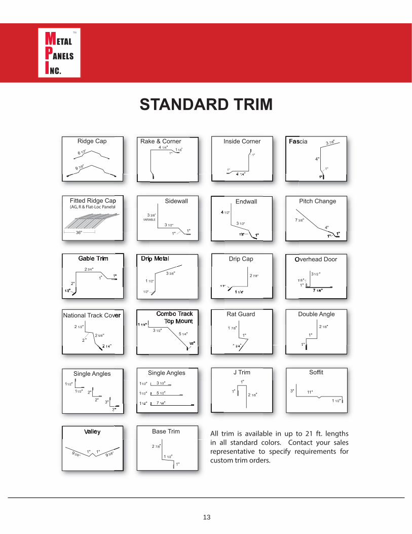
STANDARD TRIM
All trim is available in up to 21 ft. lengths in all standard colors. Contact your sales representative to specify requirements for custom trim orders.
14
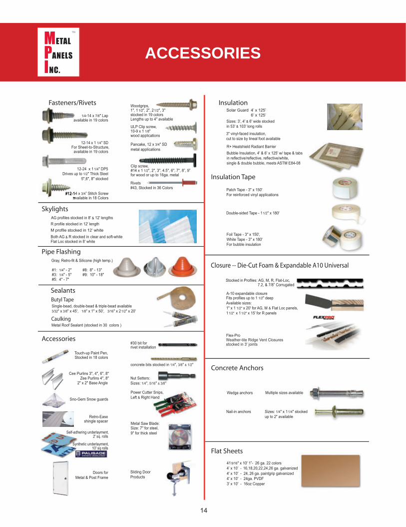
1/4-14 x 7/8" Lapavailable in 19 colors
12-14 x 1 1/4" SDFor Sheet-to-Structure,
available in 19 colors
Drives up to 1/2" Thick Steel5",6", 8" stocked
Rivets#43, Stocked in 36 Colors Patch Tape - 3" x 150'
For reinforced vinyl applications
12-24 x 1 1/4" DP5
AG profiles stocked in 8' & 12' lengthsR profile stocked in 12' length
Both AG & R stocked in clear and soft-whiteFlat Loc stocked in 8' white
Fits profiles up to 1 1/2" deep
Metal Roof Sealant (stocked in 30 colors )
Multiple sizes available
Nail-in anchors Sizes: 1/4" x 11/4" stockedup to 2" available
Touch-up Paint Pen,Stocked in 18 colors
Wedge anchors
#30 bit forrivet installation
Nut Setters:Sizes:
Size: 7" for steel,9" for thick steel
Metal Saw Blade:
Pancake, 12 x 3/4" SDmetal applications
ULP Clip screw,10-9 x 1 1/8"wood applications
Clip screw,#14 x 1 1/2", 2", 3", 4.5", 6", 7", 8”, 9”for wood or up to 16ga. metal
Foil Tape - 3" x 150',White Tape - 3" x 180'For bubble insulation
Double-sided Tape - 11/2" x 180'
Closure -- Die-Cut Foam & Expandable A10 Universal
Available sizes:1" x 1 1/2" x 20' for AG, M & Flat Loc panels,11/2" x 11/2" x 15' for R panels
Sealants
Caulking
Butyl TapeSingle-bead, double-bead & triple-bead available3/32" x 3/8" x 45', 1/8" x 1" x 50', 3/16" x 21/2" x 20'
concrete bits stocked in 1/4", 3/8" & 1/2"
Power Cutter Snips,Left & Right Hand
Sliding DoorProducts
Doors forMetal & Post Frame
Cee Purlins 3", 4", 6", 8"Zee Purlins 4", 8"
2" x 2" Base Angle
Accessories
Concrete Anchors
Flat Sheets
Pipe Flashing
Skylights
noitalusnIsteviR/srenetsaF
Insulation Tape
Gray, Retro-fit & Silicone (high temp.)
#1: 1/4" - 2"#3: 1/4" - 5"#5: 4" - 7"
#8: 8" - 13"#9: 10" - 18"
Self-adhering underlayment,2' sq. rolls
Weather-tite Ridge Vent Closuresstocked in 3' joints
419/16" x 10' 1”- 26 ga. 22 colors4’ x 10’ - 16,18,20,22,24,26 ga. galvanized4' x 10' - 24, 26 ga. paintgrip galvanized
3' x 10' - 16oz Copper
Sno-Gem Snow guards
Retro-Easeshingle spacer
Synthetic underlayment,10' sq rolls
Woodgrips,1", 11/2", 2", 21/2", 3"stocked in 19 colorsLengths up to 4" available
1/4", 5/16" & 3/8"
#12-14 x 3/4” Stitch Screwavailable in 18 Colors
Flex-Pro
A-10 expandable closure
M profile stocked in 12’ white
4' x 10' - 24ga. PVDF
Stocked in Profiles: AG, M, R, Flat-Loc, 7.2, & 7/8” Corrugated
ACCESSORIES
15
Please familiarize yourself with all installation instructions before starting work.
Prior to panel installation, the installer should examine the decking or framing to ensure that all supporting members are straight, level and plumb to prevent any panel distortion. Substructures should be designed to meet all applicable code requirements.
Panels must be installed straight, plumb and square to the eave. Some field cutting and fitting of panels and trims, as well as minor field corrections are a part of normal installation work.
Follow the manufacturer’s installation procedures, including fastener methods and creation of penetrations. Trim should be installed in proper alignment with the panels.
Sealants must be field-applied according to manufacturer’s instructions on dry, clean surfaces.
All trims, closures and accessories shown on the installation drawings are available from Metal Panels Inc. unless otherwise noted.
Oil-canning in the flat area of the panel is common to the industry and does not affect the integrity of the panel. Oil-canning is not a reason for rejection.
PRELIMINARY INSTALLATION GUIDE
The installer is responsible to insure suitable decking or purlin structure prior to the application of StrongSeam AG panels. Panel distortions caused by handling, uneven decking, ripples or laps in the underlayment, construction debris or extreme temperature changes are not cause for rejection of material.
Substructure Precautions
Panel distortion may occur if applied over misaligned or non-uniform substructure.
Check the roof deck for squareness before installing StrongSeam AG panels. Below are two methods for verifying squareness of the structure for proper panel installation.
Method 1:
Measure diagonally across one slope of the roof from similar points at the ridge and eave and obtain the same dimension. Note that it is possible that a roof is out of square even with identical measurements. To verify, additionally measure the two longest sides.
Method 2:
A 3-4-5 triangulation system may be used. Measure a point from the corner to the edge of the roof at a multiple of three (3). Measure another point from the same corner along the other edge at a multiple of four (4).
16
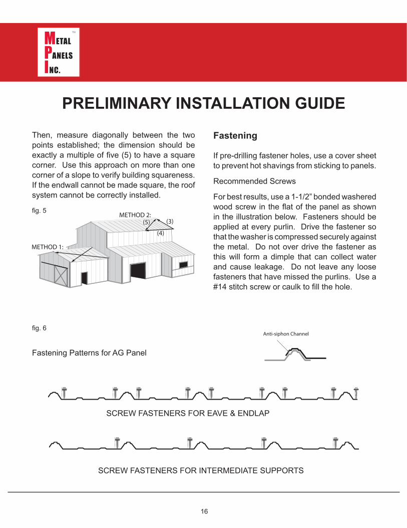
Then, measure diagonally between the two points established; the dimension should be exactly a multiple of five (5) to have a square corner. Use this approach on more than one corner of a slope to verify building squareness. If the endwall cannot be made square, the roof system cannot be correctly installed.
PRELIMINARY INSTALLATION GUIDE
Fastening
If pre-drilling fastener holes, use a cover sheet to prevent hot shavings from sticking to panels.
Recommended Screws
For best results, use a 1-1/2” bonded washered wood screw in the flat of the panel as shown in the illustration below. Fasteners should be applied at every purlin. Drive the fastener so that the washer is compressed securely against the metal. Do not over drive the fastener as this will form a dimple that can collect water and cause leakage. Do not leave any loose fasteners that have missed the purlins. Use a #14 stitch screw or caulk to fill the hole.
Anti-siphon Channel
Fastening Patterns for AG Panel
SCREW FASTENERS FOR EAVE & ENDLAP
SCREW FASTENERS FOR INTERMEDIATE SUPPORTS
fig. 5
fig. 6
17
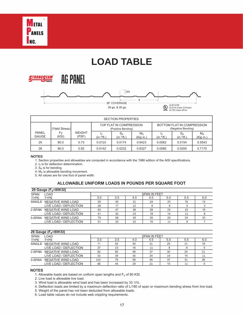
LOAD TABLE
SECTION PROPERTIES
PANELGAUGE
Fy(KSI)
TOP FLAT IN COMPRESSION BOTTOM FLAT IN COMPRESSION
WEIGHT(PSF)
Ix(in.4/ft.)
Se(in.3/ft.)
Ma(Kip in.)
Ix(in.4/ft.)
Se(in.3/ft.)
Ma(Kip in.)
29
26
80.0
80.0
0.73
0.92
0.0110
0.0142
0.0174
0.0232
0.6423
0.8327
0.0062
0.0085
0.0154
0.0200 0.7170
0.5543
NOTES 1. Section properties and allowables are computed in accordance with the 1986 edition of the AISI specifications. 2. Ix is for deflection determination. 3. Se is for bending. 4. Ma is allowable bending movement. 5. All values are for one foot of panel width.
ALLOWABLE UNIFORM LOADS IN POUNDS PER SQUARE FOOT
3/4
936” COVERAGE29 ga. & 26 ga.
UL90 #169UL2218 Class IV/ImpactUL790 Class A/Fire
AG PANEL
(Yield Stress) (Positive Bending) (Negative Bending)
29 Gauge (Fy=80KSI)SPAN IN FEETSPAN
TYPELOADTYPE
SINGLE
2-SPAN
3-SPAN
NEGATIVE WIND LOADLIVE LOAD / DEFLECTIONNEGATIVE WIND LOADLIVE LOAD / DEFLECTIONNEGATIVE WIND LOADLIVE LOAD / DEFLECTION
SPANTYPE
LOADTYPE
SINGLE
2-SPAN
3-SPAN
NEGATIVE WIND LOADLIVE LOAD / DEFLECTIONNEGATIVE WIND LOADLIVE LOAD / DEFLECTIONNEGATIVE WIND LOADLIVE LOAD / DEFLECTION
26 Gauge (Fy=80KSI)SPAN IN FEET
552863417951
71378253
10366
401747305833
311236234522
248
28183516
206
23142911
165
1911248
143
168
207
522360397644
401646305829
311137244621
258
30193715
216
24143111
185
2111269
3.0 3.5 4.0 4.5 5.0 5.5 6.0
3.0 3.5 4.0 4.5 5.0 5.5 6.0
18
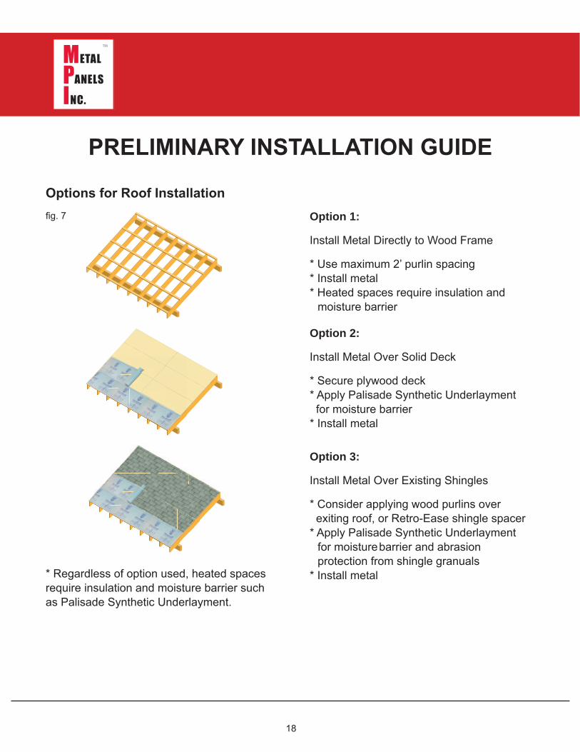
Options for Roof Installation
* Regardless of option used, heated spaces require insulation and moisture barrier such as Palisade Synthetic Underlayment.
PRELIMINARY INSTALLATION GUIDE
Option 1:
Install Metal Directly to Wood Frame
* Use maximum 2’ purlin spacing * Install metal * Heated spaces require insulation and moisture barrier
Option 2:
Install Metal Over Solid Deck
* Secure plywood deck * Apply Palisade Synthetic Underlayment for moisture barrier * Install metal
Option 3:
Install Metal Over Existing Shingles
* Consider applying wood purlins over exiting roof, or Retro-Ease shingle spacer * Apply Palisade Synthetic Underlayment for moisture barrier and abrasion protection from shingle granuals * Install metal
fig. 7
19
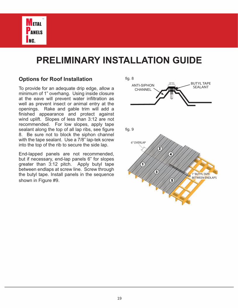
Options for Roof InstallationTo provide for an adequate drip edge, allow a minimum of 1” overhang. Using inside closure at the eave will prevent water infiltration as well as prevent insect or animal entry at the openings. Rake and gable trim will add a finished appearance and protect against wind uplift. Slopes of less than 3:12 are not recommended. For low slopes, apply tape sealant along the top of all lap ribs, see figure 8. Be sure not to block the siphon channel with the tape sealant. Use a 7/8” lap-tek screw into the top of the rib to secure the side lap.
End-lapped panels are not recommended, but if necessary, end-lap panels 6” for slopes greater than 3:12 pitch. Apply butyl tape between endlaps at screw line. Screw through the butyl tape. Install panels in the sequence shown in Figure #9.
PRELIMINARY INSTALLATION GUIDE
6” OVERLAP
1” BUTYL TAPEBETWEEN ENDLAPS
BUTYL TAPESEALANT
fig. 8
fig. 9
ANTI-SIPHONCHANNEL
20
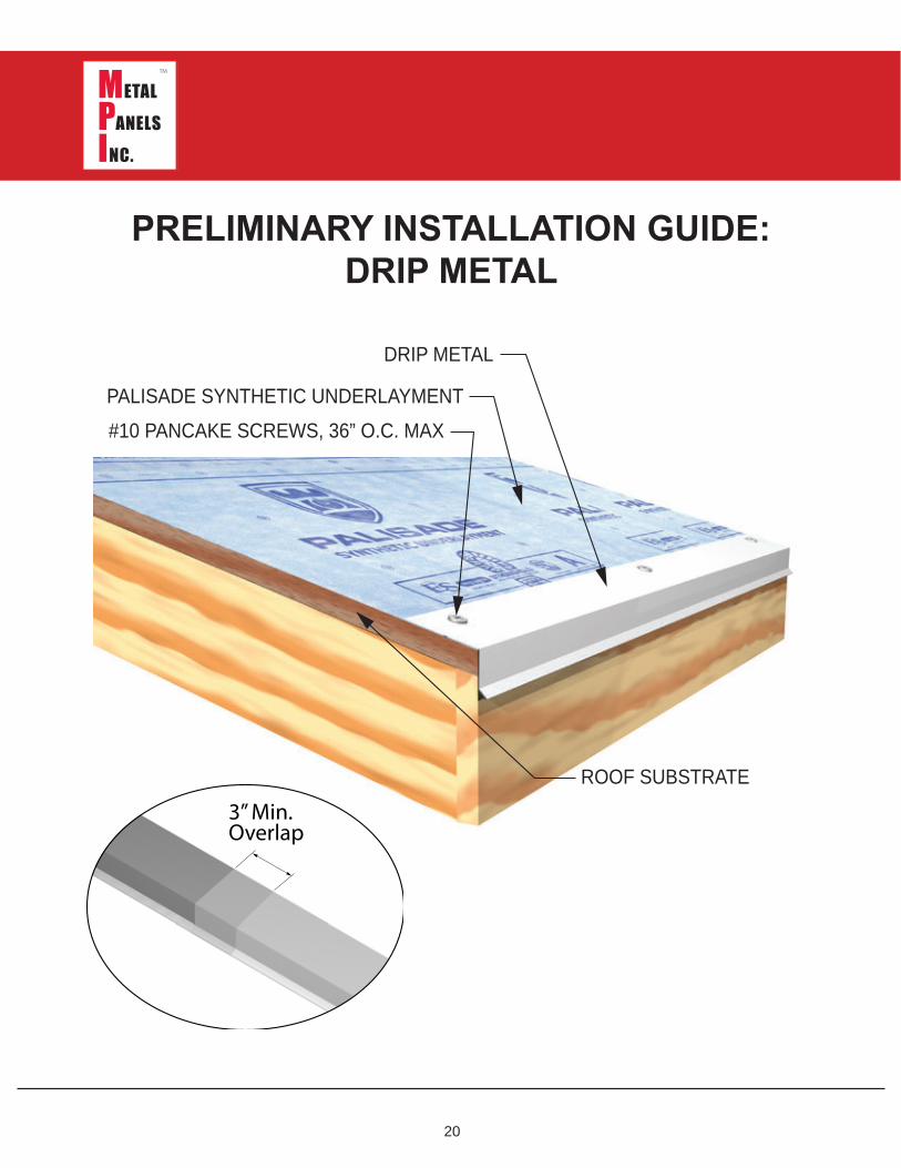
PRELIMINARY INSTALLATION GUIDE:DRIP METAL
ROOF SUBSTRATE
DRIP METAL
PALISADE SYNTHETIC UNDERLAYMENT#10 PANCAKE SCREWS, 36” O.C. MAX
3” Min. Overlap
21
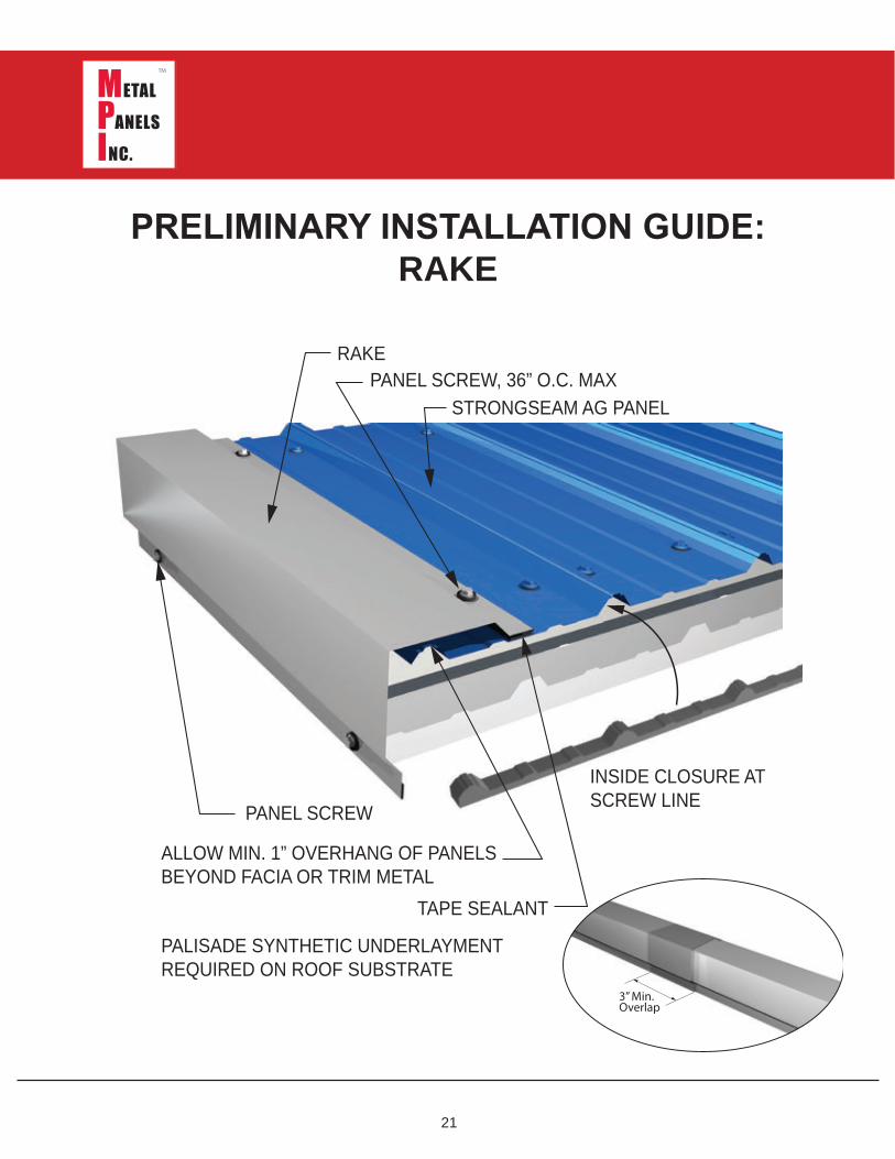
PRELIMINARY INSTALLATION GUIDE:RAKE
PANEL SCREW
TAPE SEALANT
PANEL SCREW, 36” O.C. MAXSTRONG SEAM AG PANEL
RAKE
ALLOW MIN. 1” OV ERHANG OF PANELSBEYOND FACIA OR TRIM METAL
PALISADE SYNTHETIC UNDERLAYMENTREQ UIRED ON ROOF SUBSTRATE
INSIDE CLOSURE AT SCREW LINE
3” Min. Overlap
22
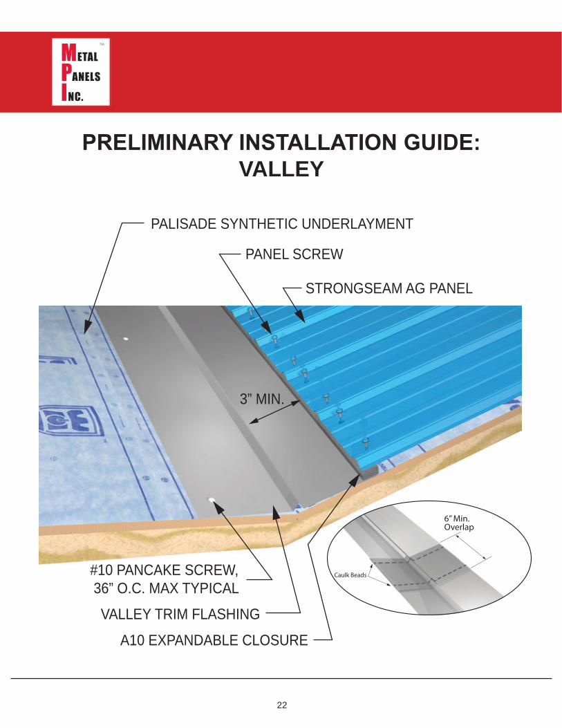
PRELIMINARY INSTALLATION GUIDE:VALLEY
PANEL SCREW
#10 PANCAKE SCREW, 36” O.C. MAX TYPICAL
V ALLEY TRIM FLASHING
STRONG SEAM AG PANEL
PALISADE SYNTHETIC UNDERLAYMENT
3” MIN.
A10 EXPANDABLE CLOSURE
6” Min. Overlap
Caulk Beads
23
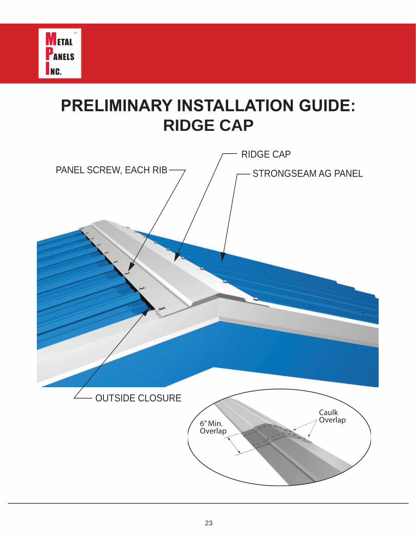
PRELIMINARY INSTALLATION GUIDE:RIDGE CAP
STRONG SEAM AG PANEL
RIDG E CAPPANEL SCREW, EACH RIB
OUTSIDE CLOSURE
6” Min.Overlap
CaulkOverlap
24
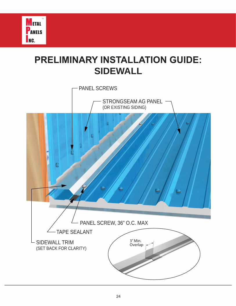
PRELIMINARY INSTALLATION GUIDE:SIDEWALL
TAPE SEALANT
SIDEWALL TRIM ( SET BACK FOR CLARITY)
PANEL SCREW, 36” O.C. MAX
STRONG SEAM AG PANEL( OR EXISTING SIDING )
PANEL SCREWS
3” Min.Overlap
25
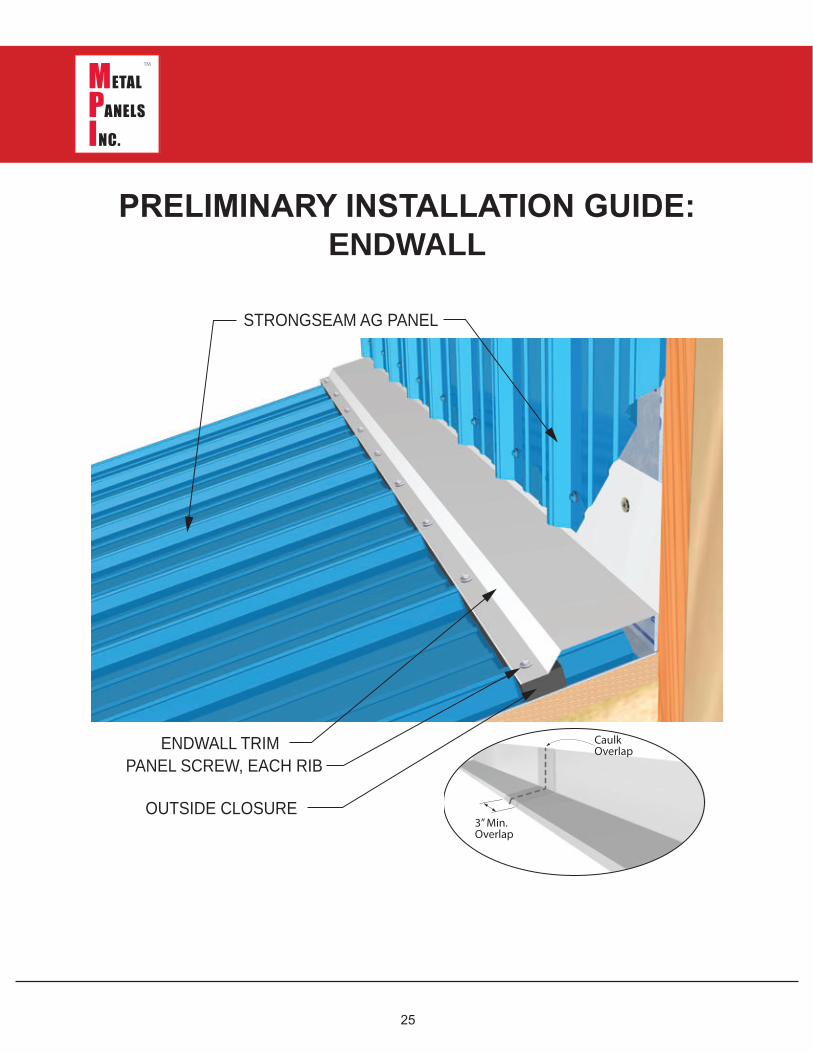
PRELIMINARY INSTALLATION GUIDE:ENDWALL
STRONGSEAM AG PANEL
ENDWALL TRIMPANEL SCREW, EACH RIB
OUTSIDE CLOSURE3” Min.Overlap
CaulkOverlap
26
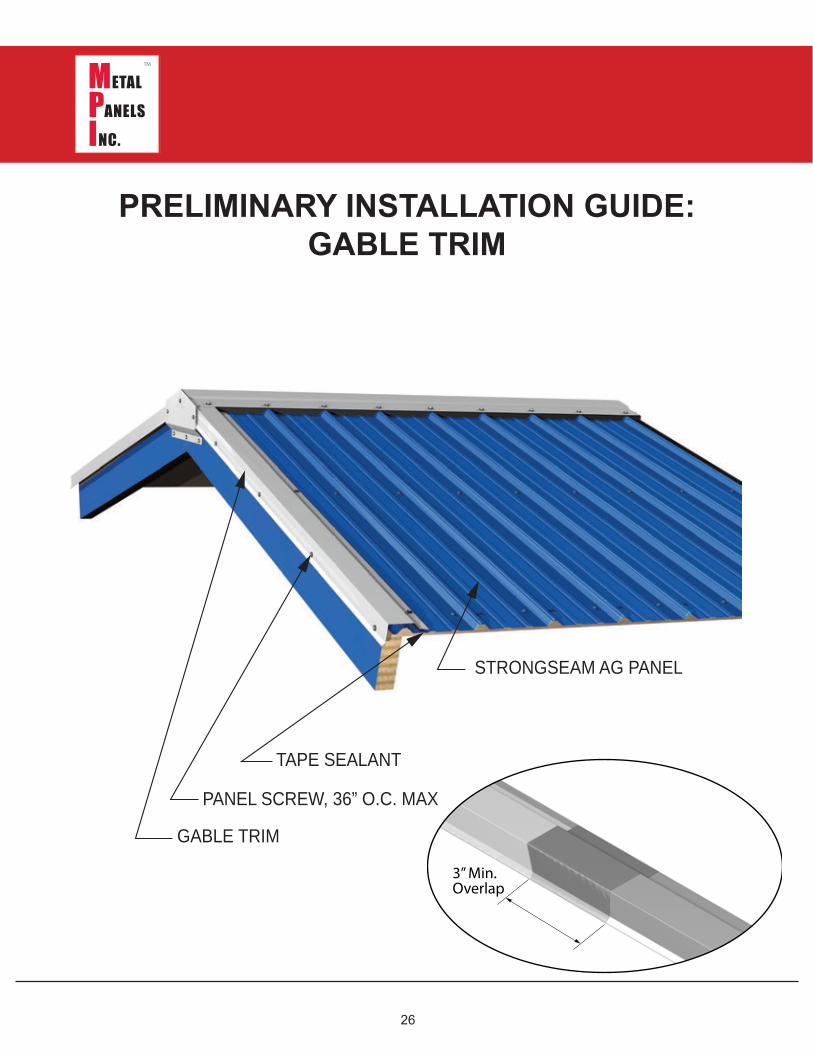
PRELIMINARY INSTALLATION GUIDE:GABLE TRIM
G ABLE TRIM
PANEL SCREW, 36” O.C. MAX
TAPE SEALANT
STRONG SEAM AG PANEL
3” Min.Overlap
27
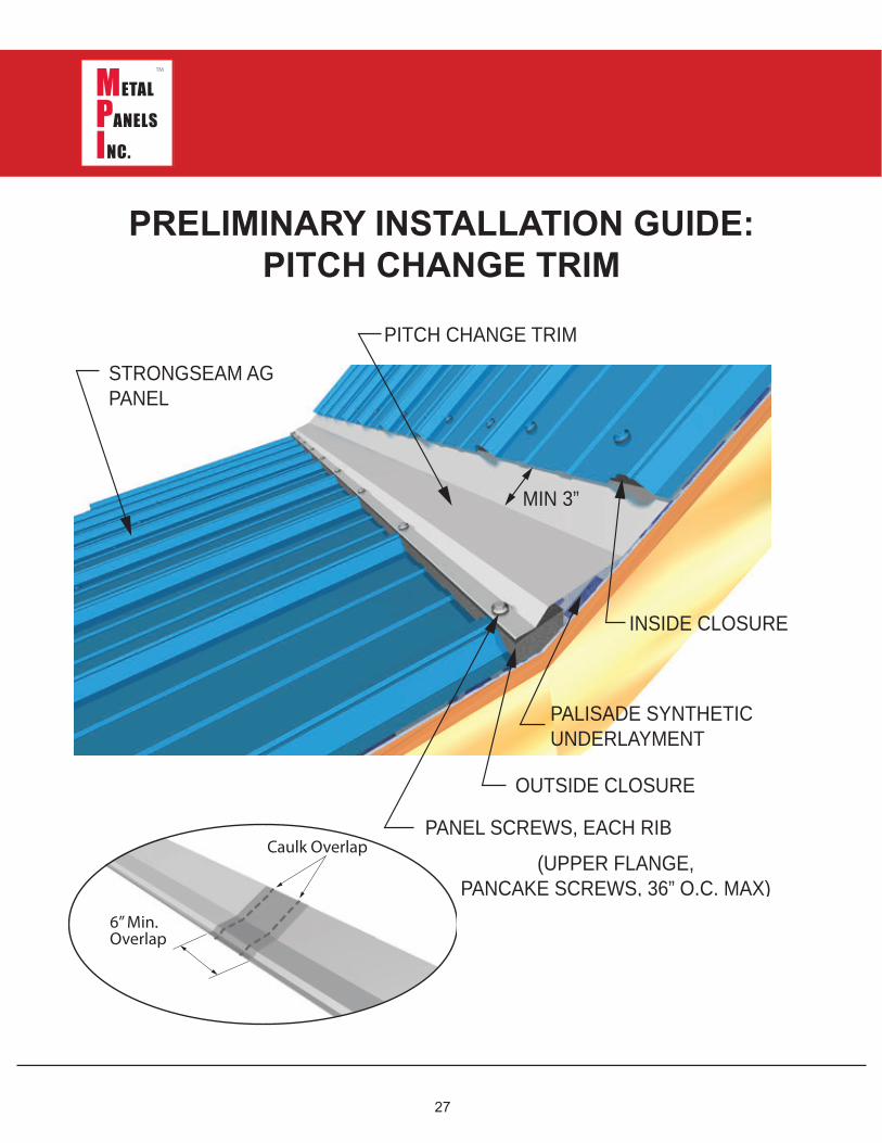
PRELIMINARY INSTALLATION GUIDE:PITCH CHANGE TRIM
PITCH CHANG E TRIM
STRONG SEAM AGPANEL
OUTSIDE CLOSURE
PANEL SCREWS, EACH RIB
MIN 3”
PALISADE SYNTHETICUNDERLAYMENT
INSIDE CLOSURE
( UPPER FLANG E,PANCAKE SCREWS, 36” O.C. MAX)
6” Min.Overlap
Caulk Overlap
28
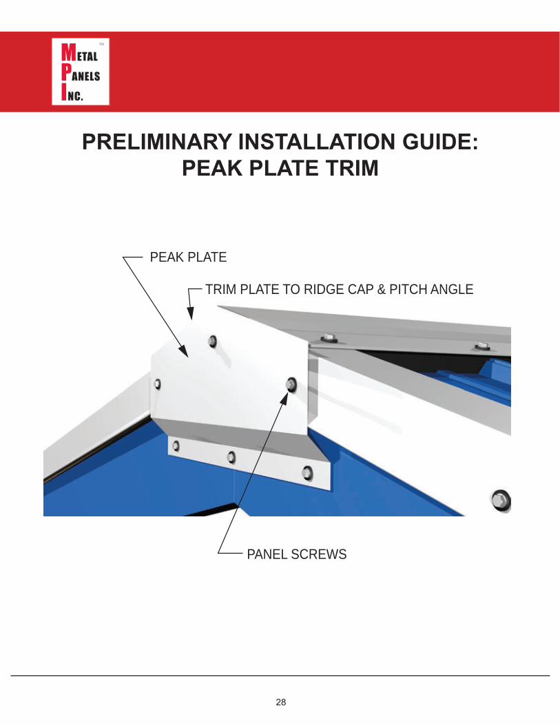
PRELIMINARY INSTALLATION GUIDE:PEAK PLATE TRIM
TRIM PLATE TO RIDG E CAP & PITCH ANG LE
PEAK PLATE
PANEL SCREWS
29
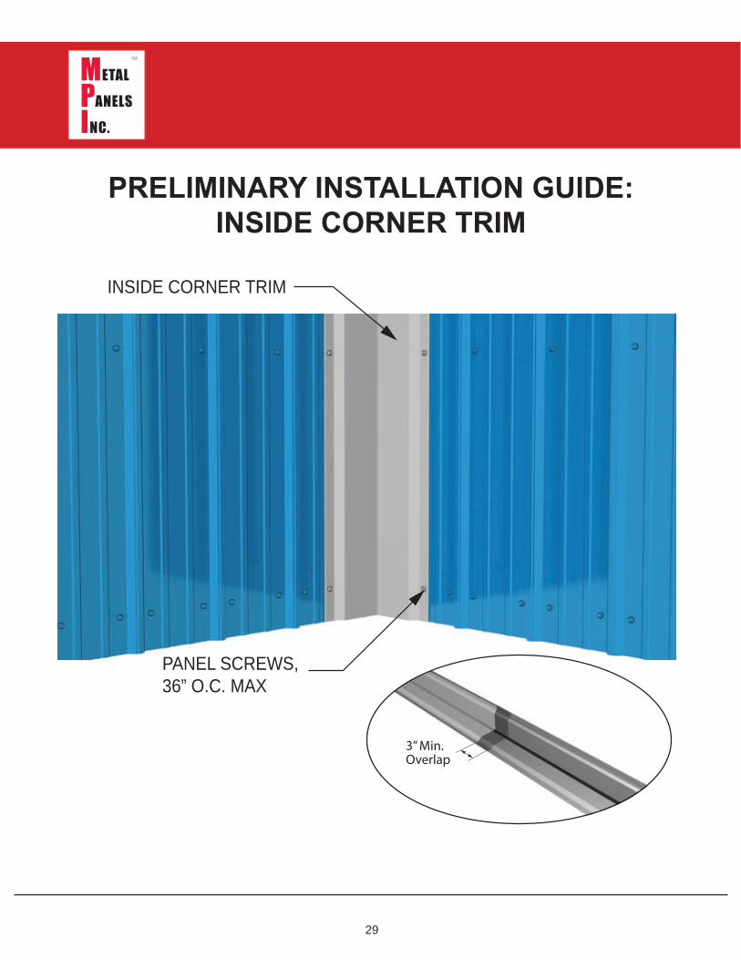
PRELIMINARY INSTALLATION GUIDE:INSIDE CORNER TRIM
INSIDE CORNER TRIM
PANEL SCREWS,36” O.C. MAX
3” Min.Overlap
30
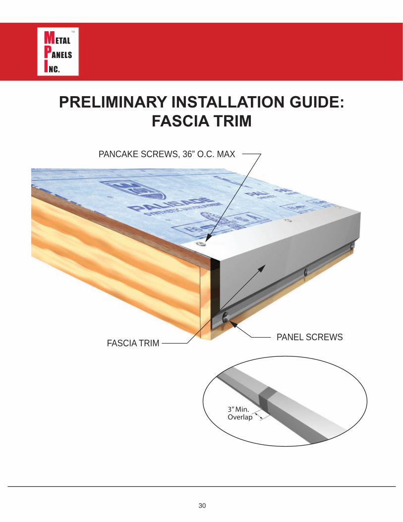
PRELIMINARY INSTALLATION GUIDE:FASCIA TRIM
FASCIA TRIM
PANCAKE SCREWS, 36” O.C. MAX
PANEL SCREWS
3” Min.Overlap
31
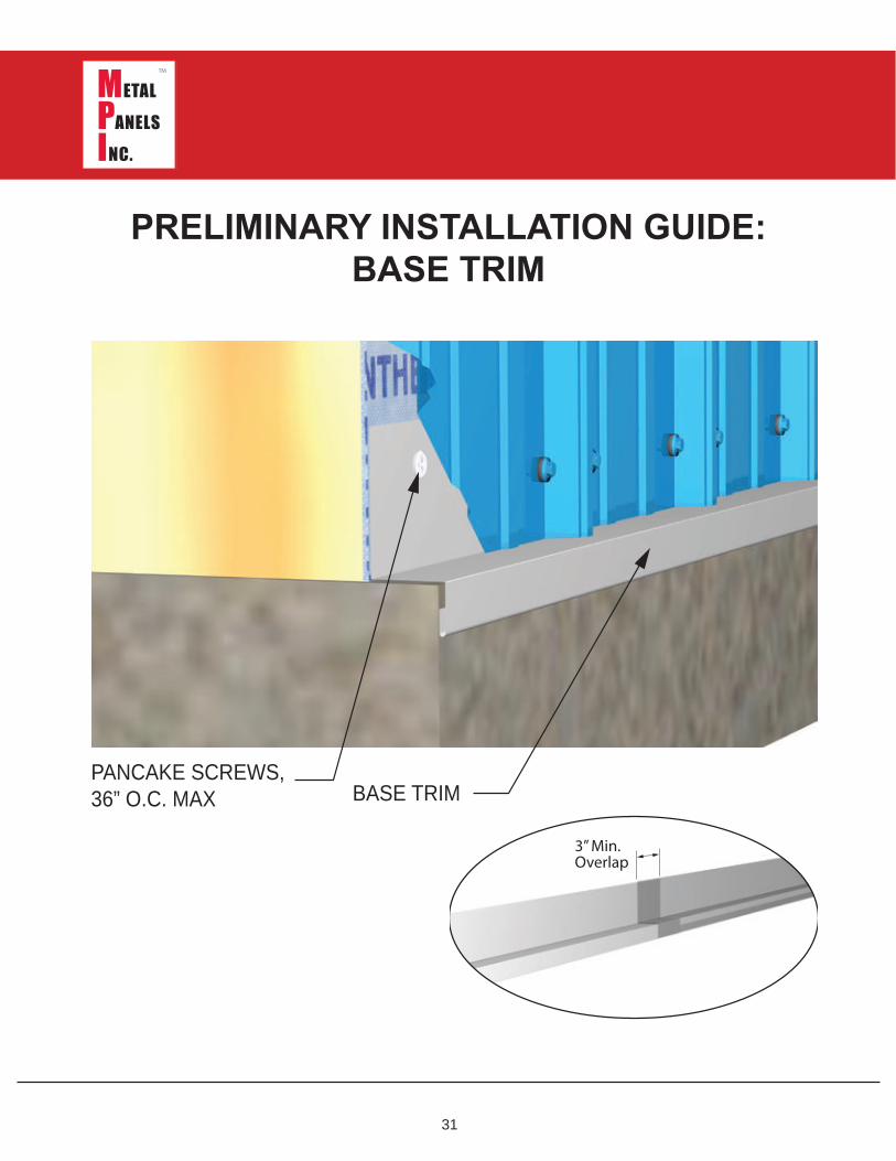
PRELIMINARY INSTALLATION GUIDE:BASE TRIM
BASE TRIMPANCAKE SCREWS,36” O.C. MAX
3” Min.Overlap
32
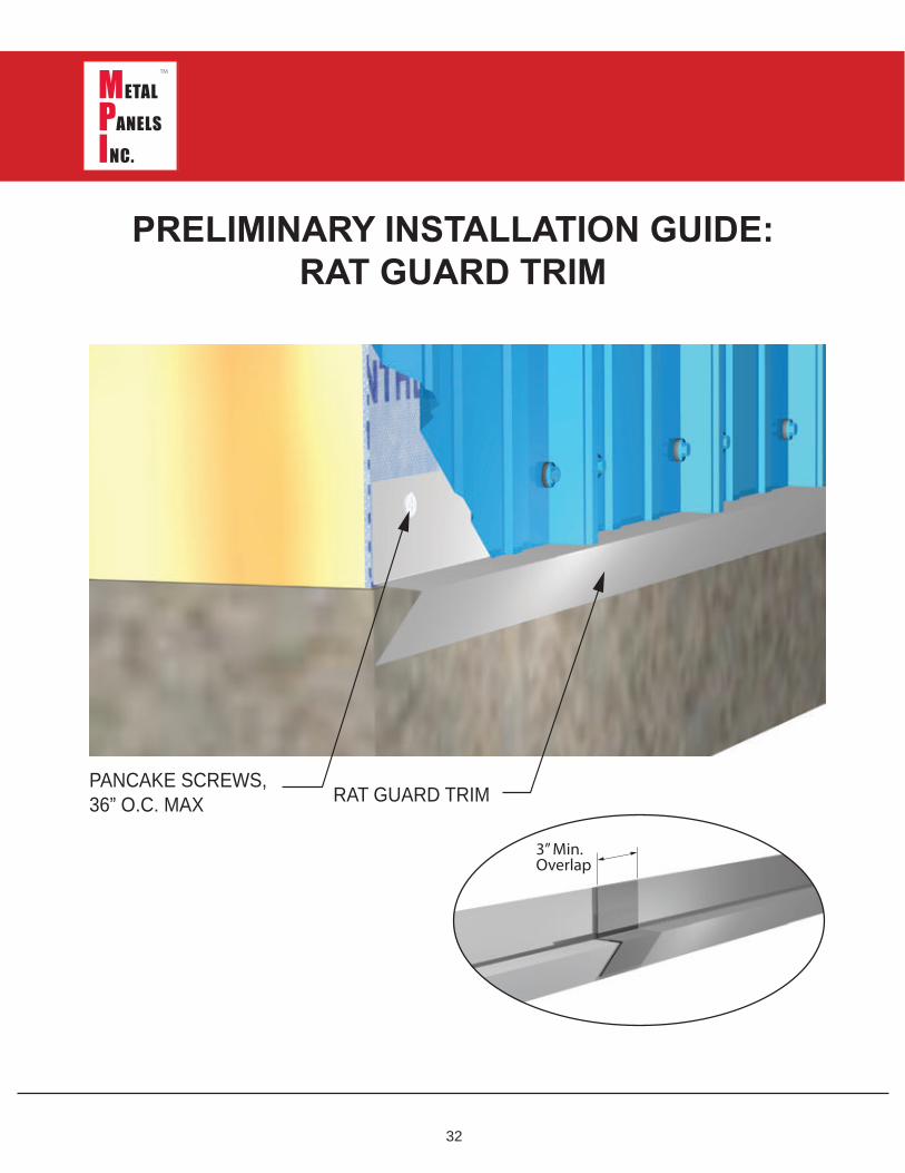
PRELIMINARY INSTALLATION GUIDE:RAT GUARD TRIM
PANCAKE SCREWS,36” O.C. MAX RAT G UARD TRIM
3” Min.Overlap
33
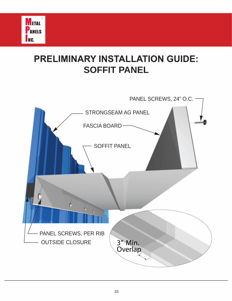
PRELIMINARY INSTALLATION GUIDE:SOFFIT PANEL
PANEL SCREWS, PER RIB
PANEL SCREWS, 2 4 ” O.C.
SOFFIT PANEL
OUTSIDE CLOSURE
STRONG SEAM AG PANEL
FASCIA BOARD
3” Min.Overlap
34
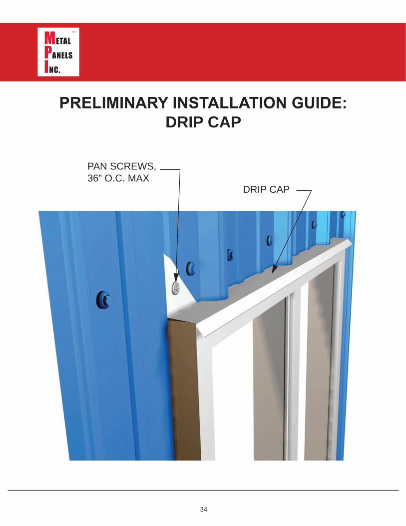
PRELIMINARY INSTALLATION GUIDE:DRIP CAP
DRIP CAP
PAN SCREWS, 36” O.C. MAX
35
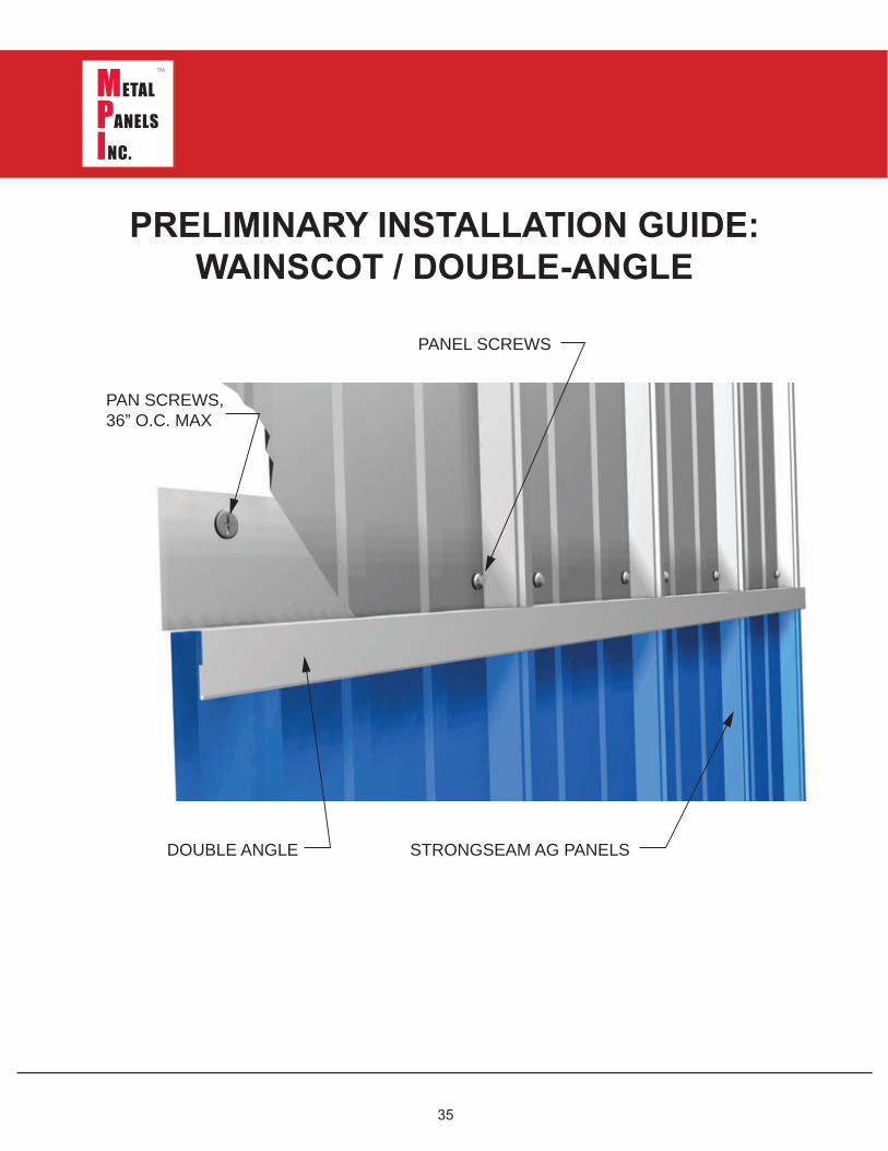
PRELIMINARY INSTALLATION GUIDE:WAINSCOT / DOUBLE-ANGLE
PAN SCREWS, 36” O.C. MAX
DOUBLE ANG LE
PANEL SCREWS
STRONG SEAM AG PANELS

36
Metal Panels Inc.131 South 147th East Avenue
Tulsa, Oklahoma 74116
(918) 641-0641 Voice(918) 641-0640 Fax
www.metalpanelsinc.com
Tulsa, Oklahoma ● Locations ● Kansas City, Kansas
Copyright 2015 © Metal Panels Inc. All rights reserved. No part of this document may be reproduced or distributed without prior written authorization.
Find Us On: