strongseam lf2a panel
TRANSCRIPT

StrongSeam LF2A Panel
Installation Manual July 2021
Tulsa, OK • Kansas City, KS • www.metalpanelsinc.com • 866-674-7657
For Open Purlin
2
De s i g n G u i d e l i n e s
This manual contains guidelines for installing Metal Panels Inc. (MPI) panels and trim. Guidelines presented herein were in effect as of this printing. Metal Panels Inc. reserves the right to change designs or specifications at any time in order to stay current with building code requirements. To ensure that you have the latest information, please contact your sales representative at Metal Panels Inc. Applica-tion and design illustrations are for your reference only, and may not be appropri-ate or specified for all environments, conditions or building designs. It is strongly recommended that all projects should be engineered and installed to conform to applicable building codes, regulations and accepted industry practices.
A roof must be designed to support certain minimum wind and snow loads. Consult local building officials to determine appropriate design load requirements. All roof systems should be designed or verified by a qualified engineer. It is the buyer’s responsibility to verify all code requirements, checking all measurements, and de-termine suitability of the product for the job. The buyer is responsible for supplying and confirming all panels and trim profiles, and actual length and quantities needed. All MPI instructions for this panel assume that a qualified firm or individual has been contracted to install this product. Failure to comply with stated recommendations voids all manufacturer responsibility for any damage or deterioration due to misuse of the product and voids any applicable warranty.

3

4
In t r o d u c t i o nThe LF2A Panel (Armco) is a mechanically-seamed architectural/structural standing seam roof system for use over open purlins or a solid deck. This panel features a return leg on both the male and female seams that help increase strength and wind uplift resistance.
Specifications The StrongSeam LF2A Panel features a 2” lock forming rib and is available in 26 ga. (solid deck only - 14” coverage), 24 ga. and 22 ga. with standard coverage of 16” and 18”. Panel can be formed as smooth, striated or 2-bead. Panels offered in 32 PVDF colors plus galvalume. Minimum recommended slope is 0.5:12.
Maximum panel lengths are constrained only by practical handling and transportation limitations, typically a maximum of 55 ft. Panels exceeding 55 ft. will be roll-formed at the jobsite.
Te s t i n gUL90 #169 Uplift Rating
UL2218 Class IV/Impact Resistance
UL790 Class A/Fire Resistance
Re c o m m e n d e d To o l s
▪ Cordless Screw Gun
▪ Snips
▪ Tape Measure
▪ Electric Metal Shear or Circular Saw
▪ Caulk Gun
▪ Pop Rivet Tool
▪ Chalk Line
▪ “Duckbill” Locking Pliers
▪ Hemming Tool
▪ Electrical Extension Cord
Installer must have experience using the tools listed above for metal roofing installation.
Safety Use extreme caution when walking on a metal roof. Metal panels may become slippery, so always wear shoes with non-slip soles. Avoid working on metal roofs during wet conditions. Do not walk on a metal roof which does not have a solid deck beneath it. If you must, walk on the purlins only. Always use appropriate safety harnesses. OSHA safety regulations should be complied with at all times.
Caution Always wear heavy gloves when working with steel panels to avoid cuts from sharp edges. When power cutting or drilling steel panels, always wear safety glasses to prevent eye injury from flying debris.
fig. 1
INTRO DU C TIO N TO INSTAL L ATIO N
0.56250.375

5
Production Lead Time
Please consult your MPI sales representative for accurate order production time. Large orders, non-standard colors or custom panel fabrication may require longer lead times.
Packaging
For standard orders, panels are crated for truck shipment. Custom shipping requirements may be accommodated at an additional charge.
(Illustration to demonstrate packaging methods only.)

6
Storage
When metal panels will NOT to be used immediately, store inside in a well-ventilated, dry location. Outdoor storage is not recommended and may void warranties; to do so is at the customer’s own risk.
Standing Seam panels are shipped with a plastic peel-off protective film, which should be removed shortly after taking receipt of the panels. Panels left in the sun, or stored for an extended amount of time may cause the protective film to permanently bond to the panel paint. Extended storage of crated panels is not recommended.
Panels must not be stored near or come in contact with salt water, corrosive chemicals, ash, or solvent fumes, or come in contact with wet or green lumber.
STO RAG E & H ANDL ING
If panel crates must be stored outside, strictly adhere to these requirements:
1. Storage area should be level, and should be located to minimize handling of crate during construction.
2. For storage on bare ground, place a plastic ground cover as a barrier under the crate to minimize exposure to moisture, dirt or dust from the soil.
3. Store crate above the ground by a minimum of 6” to allow air circulation beneath the crate, and to prevent damage from rising water.
4. Inspect stored crate frequently and repair any tears or punctures in the water-resistant cover with a compatible waterproof tape.
5. Re-cover opened crate at the end of each day to prevent entry of moisture and exposure to sunlight.

7
Protective Film Removal
Painted panels may have a protective film layer applied to the outside finish to prevent possible damage to the painted surface. Remove the protective film layer promptly, before exposing to direct sunlight and high temperatures. After exposure to heat or sunlight, the protective film cannot be removed. Never leave the protective film on the panels after installation. Metal Panels Inc. cannot be held liable for damage to metal caused by improper storage and failure to remove protective film.
Some Safety Precautions
To prevent injury, always wear gloves when working with steel panels. Wear safety glasses when cutting or drilling steel panels, and remove any metal shavings immediately to reduce risk of eye injury from flying debris. Avoid walking on metal panels. If you must walk on a metal roof, use extreme caution. Wear shoes with non-slip soles, for metal panels can become slippery even dry. Avoid working on metal roofs during wet conditions when the panels can become extremely slick. Walking or standing on a metal roof which does not have a solid deck beneath it is not recommended. If unavoidable, always walk on the purlins, never between. Do not for any reason walk on a roof made of material thinner than 29 gauge.
Roof Storage
For convenient handling, MPI LF2A panel crates can be lifted and placed on the roof by the contractor (assuming the roof can support the panel load). When lifting crated sheets, make sure they are adequately supported. Panels less than 20 ft. in length may be lifted with a forklift. When lifting crated panels in excess of 20 ft., it is recommended that a spreader bar with slings be used, or use two forklifts. When lifting, do not leave more than 1/3rd of the panel length unsupported. (See fig. 2)
Determine best location for crate placement by how much area that crate of panels will cover. Crates should be placed on the roof facing the same direction that the panels will be installed. Make certain to keep the area clear for your markings and string lines that verify squareness of roof.
Fig. 2
STO RAG E & H ANDL ING

8
STO RAG E & H ANDL ING
1. Crate should remain unopened and intact during any handling and remain so until the panels are ready to be installed.
2. Always lift crate as close as possible to its center of gravity
3. When lifting by crane, use a spreader bar of appropriate length and nylon band slings. (Do not use cable slings. They will damage panels.)
4. A panel crate of manageable length may be lifted by forklift. Set forklift forks to their maximum spacing apart, and center the load on the forks to prevent panel damage. Never lift a panel by its ends. Carry a panel by its longitudinal edge and in a vertical (not flat) position. For panels over 10 ft., two or more people should lift and carry the panel from the same edge. (see fig. 3)
5. Once a crate is opened, individual panels must be handled with care to prevent panel buckling or finish damage.
6. Gloves must always be worn when handling panels.
fig. 3
Receiving Materials
The installer has the responsibility to unload material from the delivery truck. The installer must provide suitable equipment for safely unloading all materials from the delivery truck. Optionally, MPI offers donkey/forklift truck delivery and off-load.
After receiving your order, verify the condition of the material and compare the shipment against the shipping list to ensure all ordered items have been received. If damages or shortages are discovered, note the discrepency on the shipping copy at time of delivery. If replacement material is required, you must contact Metal Panels Inc. to place the order. Report any damages or shortages to Metal Panels Inc. within 48 hours from the time of shipment.
Caution
Improper loading and unloading of crate may result in bodily harm and/or material damage. Metal Panels Inc. is not responsible for bodily injuries and/or material damages resulting from improper loading or unloading.
General Handling Each crate should be handled with care to avoid product damage. Proper handling should be used to prevent bending panels or scratching the finish. To prevent panel damage, follow these steps for unloading and handling crate:

9
Mechanical Handling
Using a Forklift
A forklift may be used for panels up to 20 ft. Set the forks at their maximum separation and center the load on the forks. When transporting crate across rough terrain, or over a long distance, use nylon straps or similar means of additional support for the crate. Never transport open crate.
Using a Crane
For lifting panel crate greater than 20 ft. in length, a crane is recommended, or two forklifts. Utilize an appropriate spreader bar to ensure even distribution of the weight to the lift points. No more than 1/3rd of the length of the panel should be left unsupported when lifting panel crate. Canvas or nylon slings should be used to lift panels. DO NOT use cable or chains – they will damage the panels.
Foot Traffic
Walking on a metal roof can cause distortion of panels and damage to the finish. Foot traffic on an installed roof system must be kept to an absolute minimum. If continuous foot traffic is necessary for maintenance over the roof, then a permanent walkway should be installed.
For foot traffic during installation, provide walking platforms to avoid any panel damage.
If walking on the roof panels is unavoidable, walk only in the flats of the panel; walking on the ribs can damage the panels.
STO RAG E & H ANDL ING
Metal roof installers must be in full compliance with all applicable safety regulations including OSHA regulations.
Field Cutting
Tin snips, portable shear or a “nibbler” type electric tool are recommended for field cutting StrongSeam LF2A panels. If a skill saw is used, the blade will generate slivers of metal chips. Any metal chips must be immediately removed from the panel because they will damage the finish and induce rust staining.
One approach to addressing this problem is to flip the panels over when cutting. The metal slivers can be brushed away from the back side, preventing finish damage to the top side of the panels.
All roof or panel surfaces must be free of debris at all times. Installed surfaces should be wiped clean at the end of each work day. Never cut panels over other metal surfaces. Metal shavings will rust on the surface which will void the warranty.
Always wear goggles for eye protection when cutting metal panels.
Caution
Caution

10
STO RAG E & H ANDL INGTouch-up Paint
All painted panels, trim and flashings have a factory-applied heat-cured finish. During handling and installation, a panel may become slightly scratched or nicked. Paint pens are available in matching colors. It is recommended to use the sharp edge of the chisel tip to apply touch-up paint only to those areas that are in need of repair (apply touch-up paint to the scratch itself. Do not paint over panel finish). Be aware that touch-up paint does not have the superior chalk and fade resistance of the factory-applied finish and will likely discolor at an accelerated rate. Periodic touch-up may be required to maintain color match. Due to the limitations and formulation of field-applied touch-up paint, there is no warranty offered for color match or durability of the product.
When touching up scratches in pan-els or flashing, it is VERY IMPORTANT not to over paint the area to be touched up. Because of the curing solvent which must be added, air-dry formula touch-up paint WEATHERS DIFFERENTLY than the thermoset formula paint which is applied on the coil coating line. For this reason, excessive strokes will create an unsightly appearance and will worsen over time, becoming aesthetically unacceptable.
Please see MPI’s Touchup Paint Flyer for complete instructions.
Select a paint pen that matches your panel color. Shake for 1 to 2 minutes.
Prime the pen by gently pressing down on cardboard or scrap material. Stop when you see paint appear on tip.
Test for color match on a small area out of line of sight. Allow to dry completely.
Apply a fine line of paint to scratch area only. Do NOT over-paint or blend.

11
Design Considerations
Insulation & Ventilation
Properly designed and installed vapor barriers and ventilation systems prevent condensation and the resulting moisture damage and loss of insulation efficiency.
When highly-humid air contacts building surfaces that are below the dew point temperature of the air, condensation will occur.
Proper insulation can provide resistance to heat transfer and protection against condensation forming on cooler surfaces within the building or the roof system.
The building designer is responsible to specify an appropriate vapor retarder and insulation system for the project. Basic guidelines for control of condensation are as follows:
1. Faced insulation (insulation with vapor retarder) should be installed with the facing toward the warm side of the insulated area, typically, the interior of a building.
2. Insulation R-value must be high enough to maintain the temperatures of the vapor retarder above the interior dew point, using “worst-case” outside temperatures for a reference
DE SIG N & INSTAL L ATIO N
3. Seal all seams and penetrations of the vapor barrier in order to provide a continuous membrane to resist the passage of water vapor.
4. Structure ventilation contributes significantly to reducing condensation. Whether by passive or active (powered) venting, air movement to the outside of the building reduces interior vapor pressure.
Buildings with attic space or retrofitted metal roofing system require vents at the eaves and peak of the roof in order to prevent a buildup of moisture under the roof.
Check local building codes for proper ventilation practices for your area.
VENT ATEAVE
ATTICINSULATION
RIDGE VENT

12
Roofing Substrates
In warm weather climates, synthetic underlayment should be used over the existing decking. The high temperature resistance prevents it from sticking to the panels and tearing, which can occur with asphalt-based felt paper.
In colder climates, ice and water shield should be used at the valley and eave. Apply over the decking before installation of the synthetic underlayment.
Use appropriate safety precautions when applying synthetic substrates because they can be slippery.
DE SIG N & INSTAL L ATIO N
Roof Pitch Chart
Reference the chart below for specifying StrongSeam LF2A panels and trims.
Caution
P ITC H PITCH FACTOR H IP / V AL L E Y FACTOR
P ITC H PITCH FACTOR H IP / V AL L E Y FACTOR
3:12 1.0308 1.4362 8:12 1.2019 1.56354:12 1.0541 1.4530 9:12 1.2500 1.60085:12 1.0833 1.4743 10:12 1.3017 1.64156:12 1.1180 1.5000 11:12 1.3566 1.68537:12 1.1577 1.5298 12:12 1.4142 1.7320
L
H
(L) x (H) [Hip/Valley]
S
F
Peak
Eave
(F) x (Pitch Factor)=S
fig. 4

13
STANDARD TRIMS
V ARIAB LEPITCH
4 .0
1.25
0 .5
1.7 5
4 0 o
DRIP METAL
3 .3 7 5
2.00 .5
2.125
RAKE J -CLIP 4 .0
5.7 5
2.25COLORINSIDE
RIDGE J METAL
2.5
8 5o
8 5o
3 .0
0 .52.0
SIDEWALL FLASHING
COLOR
1.5
2.0
1.5
Z -CLOSU RE
1.25
2.0 1.5
COLOR
1.25 PERF.
V ENTED Z -CLOSU RE
V ARIAB LE7 .5
0 .5
OPENNOTCH FOR LAP
7 .5
STANDARD 16 ” RIDGE CAPAND FOR V ENTED RIDGE
10 .5
OPEN HEM0 .5
5.0
CAU LK ANDPOP-RIV ET( Ri v e t s 12" o n c e n t e r )
10 .5
5.0
0 .5
VARIABLE
115o
1.0
STANDARD V ALLEY
5.00 .5
2.5
V ARIAB LE
OPEN
ROOF TO WALL
0 .51.7 5
3 .0
5.5
0 .5
OPEN
4 5o
RAKEMETAL 1.5”
NOTCH FOR LAP( LEFT/RIGHT)
V ARIAB LE
OPENNOTCH FOR LAP
OPTIONAL CLEAT
CAU LK &POP-RIV ET
8 .5 0 .5
2.0
7 .0
CHANGE OF PITCH
V ARIAB LE
5.5
0 .5
OPENNOTCH FOR LAP
5.5STANDARD 12” RIDGE CAP
0 .6 25
0 .6 252.125
2.5
0 .6 25
0 .7 5
2.25
6 .0
V ENTED RIDGE J1.25 PERF.

14
AC C E SSO RIE S
1/4-14 x 7/8" Lapavailable in 19 colors
12-14 x 1 1/4" SDFor Sheet-to-Structure,
available in 19 colors
Drives up to 1/2" Thick Steel5",6", 8" stocked
Rivets#43, Stocked in 36 Colors Patch Tape - 3" x 150'
For reinforced vinyl applications
12-24 x 1 1/4" DP5
AG profiles stocked in 8' & 12' lengthsR profile stocked in 12' length
Both AG & R stocked in clear and soft-whiteFlat Loc stocked in 8' white
Fits profiles up to 1 1/2" deep
Metal Roof Sealant (stocked in 30 colors )
Multiple sizes available
Nail-in anchors Sizes: 1/4" x 11/4" stockedup to 2" available
Touch-up Paint Pen,Stocked in 18 colors
Wedge anchors
#30 bit forrivet installation
Nut Setters:Sizes:
Size: 7" for steel,9" for thick steel
Metal Saw Blade:
Pancake, 12 x 3/4" SDmetal applications
ULP Clip screw,10-9 x 1 1/8"wood applications
Clip screw,#14 x 1 1/2", 2", 3", 4.5", 6", 7", 8”, 9”for wood or up to 16ga. metal
Foil Tape - 3" x 150',White Tape - 3" x 180'For bubble insulation
Double-sided Tape - 11/2" x 180'
Closure -- Die-Cut Foam & Expandable A10 Universal
Available sizes:1" x 1 1/2" x 20' for AG, M & Flat Loc panels,11/2" x 11/2" x 15' for R panels
Sealants
Caulking
Butyl TapeSingle-bead, double-bead & triple-bead available3/32" x 3/8" x 45', 1/8" x 1" x 50', 3/16" x 21/2" x 20'
concrete bits stocked in 1/4", 3/8" & 1/2"
Power Cutter Snips,Left & Right Hand
Sliding DoorProducts
Doors forMetal & Post Frame
Cee Purlins 3", 4", 6", 8"Zee Purlins 4", 8"
2" x 2" Base Angle
Accessories
Concrete Anchors
Flat Sheets
Pipe Flashing
Skylights
noitalusnIsteviR/srenetsaF
Insulation Tape
Gray, Retro-fit & Silicone (high temp.)
#1: 1/4" - 2"#3: 1/4" - 5"#5: 4" - 7"
#8: 8" - 13"#9: 10" - 18"
Self-adhering underlayment,2' sq. rolls
Weather-tite Ridge Vent Closuresstocked in 3' joints
419/16" x 10' 1”- 26 ga. 22 colors4’ x 10’ - 16,18,20,22,24,26 ga. galvanized4' x 10' - 24, 26 ga. paintgrip galvanized
3' x 10' - 16oz Copper
Sno-Gem Snow guards
Retro-Easeshingle spacer
Synthetic underlayment,10' sq rolls
Woodgrips,1", 11/2", 2", 21/2", 3"stocked in 19 colorsLengths up to 4" available
1/4", 5/16" & 3/8"
#12-14 x 3/4” Stitch Screwavailable in 18 Colors
Flex-Pro
A-10 expandable closure
M profile stocked in 12’ white
4' x 10' - 24ga. PVDF
Stocked in Profiles: AG, M, R, Flat-Loc, 7.2, & 7/8” Corrugated

15
Please familiarize yourself with all installation instructions before starting work.
Prior to panel installation, the installer should examine the decking or framing to ensure that all supporting members are straight, level and plumb to help prevent panel distortion. Substructures should be designed to meet all applicable code requirements.
Panels must be installed straight, plumb and square to the eave. Some field cutting and fitting of panels and trims, as well as minor field corrections are a part of normal installation work.
Follow the manufacturer’s installation procedures, including fastener methods and creation of penetrations. Trim should be installed in proper alignment with the panels.
Sealants must be field-applied according to manufacturer’s instructions on dry, clean surfaces.
All trims, closures and accessories shown on the installation drawings are available from Metal Panels Inc. unless otherwise noted.
Oil-canning in the flat area of the panel is common to the industry and does not affect the integrity of the panel. Oil-canning is not a reason for rejection.
PRELIMINARY INSTALLATION GUIDE
The installer is responsible to insure a suitable decking prior to the application of StrongSeam LF2A panels. Panel distortions caused by handling, uneven decking, ripples or laps in the underlayment, construction debris or extreme temperature changes are not cause for rejection of material.
Substructure Precautions
Panel distortion may occur if applied over misaligned or non-uniform substructure. Check the roof deck for squareness before installing StrongSeam LF2A panels.

16
Two methods for verifying squareness of the structure for proper panel installation are shown below.
Method 1:
Measure diagonally across one slope of the roof from similar points at the ridge and eave and obtain the same dimension. Note that it is possible that a roof is out of square even with identical measurements. To verify, additionally measure the two longest sides.
PRELIMINARY INSTALLATION GUIDE
3 X4X
5X
METHOD 2:
METHOD 1:
1X
1X
Method 2:
A 3-4-5 triangulation system may be used. Measure a point from the corner to the edge of the roof at a multiple of three (3). Measure another point from the same corner along the other edge at a multiple of four (4)
Then, measure diagonally between the two points established; the dimension should be exactly a multiple of five (5) to have a square corner. Use this approach on more than one corner of a slope to verify building squareness. If the endwall cannot be made square, the roof system cannot be correctly installed.

17
General Installation OverviewFamiliarize yourself with all installation instructions before starting work. Before beginning installation, you should examine the substrate or framing to ensure that all supporting members are straight, level, and plumb to avoid any panel distortion. Substructures should be designed and constructed to meet all necessary code requirements.
Some field cutting and fitting of panels and trims is to be expected by the installer and minor field corrections are a part of normal installation work.
It is the responsibility of the installer to ensure a suitable substrate prior to the application of a standing seam roof. Pan wave, commonly known as “oil-canning” in the panel can be caused by an uneven substrate, ripples, or laps in the vapor barrier, debris, protruding nails, staples or screws and are not defects in the material and are not the responsibility of Metal Panels Inc.
Oil-canning distortion in the flat area of the panels is common to the industry and does not affect the integrity of the panel. Therefore, oil-canning is not a reason for rejection. Optional striations reduce the frequency and severity of oil-canning.
All trims, tools, and accessories shown on the installation drawings are available from Metal Panels Inc. unless otherwise noted.
PRELIMINARY INSTALLATION GUIDE
The panels should be installed plumb, straight and square to the eave. To keep the bottom edge of the roof perfectly straight and even, the panels must be installed square to the bottom edge. Begin by checking the roof for square; if it is square, you may pull the layout marks directly from the edge of the rake.
If the roof isn’t perfectly square, install the first panel parallel to your square line, making sure that the Rake-J clip does not hang over the gable edge of the roof sheathing. Any overhang of the rake J-clip can prevent the rake trim from fitting tight against the rake.
Note that care must be taken when aligning metallic panels. All metallic panels must run the same direction for a uniform appearance. See directional arrows on the underside of the panels and make certain that they all run the same direction.

18
Panel Installation1. Panels should be installed perpendicular
to the ridge for ridge trim attachment. Check panel alignment.
2. Attach Rake-J clip to roof with low-profile pancake screws spaced at 30” on center. Female leg of the first panel rests inside J-clip.
3. Align the female edge of the first panel with the chalk like that was snapped at the rake edges. This line can be 0” – 1 ¾” from the rake.
4. Fasten the panel along the male edge with panel clips, using #12-14x1” HwH TEC 3 screws, no washer. Place clips no more than 5’ O.C. apart along the length of the panel. (See max spacing chart) Panel will be hooked over drip metal.
PRELIMINARY INSTALLATION GUIDE
FASTENER SPACINGFasten panel securely using two screws per clip on every purlin.
O P E N P U RL IN SP AC ING 24 ga. ........................................MAX 5’ O.C.
RAKE J CLIP
LF2 A PANEL
RAKE TRIM
PANCAKE SCREW
POP-RIVET OR SCREW
PANEL SCREW W/ WASH ER( FOR H IGH WIND AREAS)
INSID EANGLE

19
Eave Termination without Fasteners (Recommended)
Panels terminated with a hemming tool to provide a smoother appearance.
Step 1: Create a tab in the panel by cutting a notch in both sides of the panel. Cut through the male and female ribs 1” up from panel end. See illustration below.
Step 2: Place the hemming tool over the tab edge as shown below.
Step 3: With the hemming tool bend the tab down and under to form a 180o bend.
5. Align the second panel female edge
with the starter panel male edge. Panels must be flush to one another. Remember, panels should hook onto drip edge.
6. Lightly press panel over clips at the seam. Seat panels from the eave to the ridge, then run seamer from eave to ridge. Attach the second panel in place using TEC screws and panel clips.
7. Continue to apply panels as in steps 5 and 6.
Eave TerminationPanels at the eave can be terminated in two ways; with hems (recommended) or with fasteners (not allowed for a watertightness warranty). Each will depend on the aesthetic consideration or warranty determined by the installer or building owner.
PRELIMINARY INSTALLATION GUIDE
TRIM PANELS BACK 1” ATMAJOR RIBS AS SHOWN
BEND TAB TOFORM HEM
PANELBENDER

20
Step 4: The panel is then ready to be installed over the drip edge trim, using the lip on the drip edge trim to secure the panel in place at the eave.
Eave Termination with Fasteners (Alternative: Does NOT qualify for
watertightness warranty)
Panels can be fastened along the eave with a #10 x 1” painted neoprene metal-to-metal fastener. Use butyl tape under the panel. Fasten along a line parallel to the eave edge and aligned to the eave strut. The fasteners can be spaced 4” apart in the minor rib striations, as shown below. When using the drip edge trim to terminate the eave, panels must be ordered approximately 1”-2” longer than the ridge-to-eave length to account for the desired overhang.
PRELIMINARY INSTALLATION GUIDE
OPEN PANEL HEM
Standard drip metal may be used for screw-down applications.
BUTYL TAPE
21
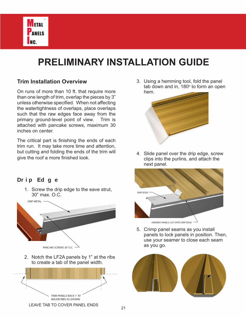
3. Using a hemming tool, fold the panel tab down and in, 180o to form an open hem.
4. Slide panel over the drip edge, screw clips into the purlins, and attach the next panel.
5. Crimp panel seams as you install panels to lock panels in position. Then, use your seamer to close each seam as you go.
Dr i p E d g e1. Screw the drip edge to the eave strut,
30” max. O.C.
2. Notch the LF2A panels by 1” at the ribs to create a tab of the panel width.
PANCAKE SCREWS 30” O.C.
DRIP METAL
PRELIMINARY INSTALLATION GUIDE
Trim Installation OverviewOn runs of more than 10 ft. that require more than one length of trim, overlap the pieces by 3” unless otherwise specified. When not affecting the watertightness of overlaps, place overlaps such that the raw edges face away from the primary ground-level point of view. Trim is attached with pancake screws, maximum 30 inches on center.
The critical part is finishing the ends of each trim run. It may take more time and attention, but cutting and folding the ends of the trim will give the roof a more finished look.
LEAVE TAB TO COVER PANEL ENDS
DRIP EDGE
HEMMED PANELS CLIP ONTO DRIP EDGE
TRIM PANELS BACK 1” ATMAJOR RIBS AS SHOWN

22
3. For high wind areas, install the rake trim with pop-rivets 30” O.C. onto the rake J-clip, then using panel screws along the outside edge of the rake, 30” max. O.C.
4. 26ga.rake trim comes standard at 10’ 2”, 24ga. at 10’ 0”. For longer runs, overlap the rakes by 3”, using a bead of sealant between laps.
Rake Trim
1. Install the continuous rake j-clip to the framing before installing panels using pancake screws, 30” max O.C.
2. If roof requires a partial panel, measure width and add 1”, then use a folding tool to bend a 90o leg.
PRELIMINARY INSTALLATION GUIDE
RAKE J CLIP
LF2 A PANEL
RAKE TRIM
PANCAKE SCREW
POP-RIVET OR SCREW
PANEL SCREW W/ WASH ER( FOR H IGH WIND AREAS)
INSID EANGLE
TAB AND FOLD TO CREATEAN ENDCAP. RIVET IN PLACE
RAKE TRIM
LF2A PANELNOTCHED & HEMMED
RAKE CLIP
LF2A PANEL NOTCHED & HEMMED,FITTED TO DRIP EDGE
RAKE J-CLIP
23
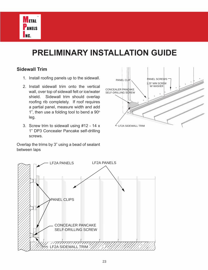
Sidewall Trim1. Install roofing panels up to the sidewall.
2. Install sidewall trim onto the vertical wall, over top of sidewall felt or ice/water shield. Sidewall trim should overlap roofing rib completely. If roof requires a partial panel, measure width and add 1”, then use a folding tool to bend a 90o leg.
3. Screw trim to sidewall using #12 - 14 x 1” DP3 Concealer Pancake self-drilling screws.
Overlap the trims by 3” using a bead of sealant between laps
PRELIMINARY INSTALLATION GUIDE
1.25” M/M SCREWW/ WASHER
LF2A SIDEWALL TRIM
PANEL SCREWS
CONCEALER PANCAKESELF-DRILLING SCREW
PANEL CLIP
PANEL CLIPS
CONCEALER PANCAKESELF-DRILLING SCREW
LF2A PANELS LF2A PANELS
LF2A SIDEWALL TRIM
24
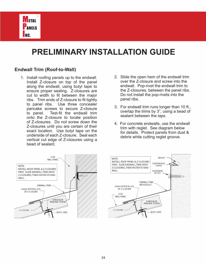
2. Slide the open hem of the endwall trim over the Z-closure and screw into the endwall. Pop-rivet the endwall trim to the Z-closures, between the panel ribs. Do not install the pop-rivets into the panel ribs.
3. For endwall trim runs longer than 10 ft., overlap the trims by 3”, using a bead of sealant between the laps.
4. For concrete endwalls, use the endwall trim with reglet. See diagram below for details. Protect panels from dust & debris while cutting reglet groove.
Endwall Trim (Roof-to-Wall)1. Install roofing panels up to the endwall.
Install Z-closure on top of the panel along the endwall, using butyl tape to ensure proper sealing. Z-closures are cut to width to fit between the major ribs. Trim ends of Z-closure to fit tightly to panel ribs. Use three concealer pancake screws to secure Z-closure to panel. Test-fit the endwall trim onto the Z-closure to locate position of Z-closures. Do not screw down the Z-closures until you are certain of their exact location. Use butyl tape on the underside of each Z-closure. Seal each vertical cut edge of Z-closures using a bead of sealant.
PRELIMINARY INSTALLATION GUIDE
LF2 AWALL PANEL
END WALL TRIMCAULK VERTICAL LEG
OF Z-CLOSURE
CONCEALERPANCAKE SCREW
Z-CLOSUREBUTYL TAPE
NOTE: INSTALL ROOF PANEL & Z-CLOSURES FIRST. SLIDE ENDWALL TRIM ONTO Z-CLOSURES, THEN FASTEN TO END-WALL.
LF2 A WALL PANEL
END WALL TRIMWITH REGLET
CAULK VERTICAL LEG OF Z-CLOSURE
CONCEALERPANCAKE SCREW
Z-CLOSUREBUTYL TAPE
NOTE: INSTALL ROOF PANEL & Z-CLOSURES FIRST. SLIDE ENDWALL TRIM ONTO Z-CLOSURES, THEN FASTEN TO END-WALL.
REGLET
CONTINUOUSCAULK
FASTENERS20” O.C.

25
the high outsides of the valley at every purlin, pop-rivet at eave drip metal
6. Install valley cleats 4”- 5” up from the center valley rib using low-profile pancake screws and sealant. Seal the cleat to the valley using butyl tape or caulk.
7. Fabricate an open hem on each panel at the correct pitch for the valley. Slide the panel up to engage the cleat, fit the panel ribs together, and screw male side of panel to decking. Using a seamer, close the seam.
Valley Installation1. Bolt together 14ga Support angles as
shown, and attach at purlins using low profile fasteners
2. Attach 48” 16ga galvanized liner panel directly over the valley support angle assembly. Screw down at purlins using low profile fasteners. Trim flush to valley eave.
3. Apply peel & stick underlayment onto the liner panel. Cover liner panel, or center full width of underlayment if slightly less wide
4. Prepare and fit the valley. Using a folding tool, hem the eave bottom end of the valley 1” and slide over the drip edge, if used. If flush drip metal is used, fold valley hem down over drip metal.
5. Install the valley to the support assembly, placing low-profile pancake head screws up as far as possible on
PRELIMINARY INSTALLATION GUIDE
EXPLODED VIEW
14g SUPPORTANGLE
OPEN PURLINVALLEY
(NON-WTW)24” VALLEY
PEEL & STICKUNDERLAYMENT48” 16ga GALVANIZED LINER
CLEAT
LF2A PANEL

26
4. Slide the open hem of the Change Of Pitch trim over the Z-closure and screw the trim to the upper decking using low-profile pancake head m/m screws. Pop-rivet trim to Z-closures.
5. Install cleats 2” up from the center of Change Of Pitch trim using low-profile pancake screws and sealant. Seal the cleat to the trim using butyl tape or caulk. Apply panels to upper roof overlapping COP transition by 5”.
6. Fabricate an open hem on each panel at the correct pitch for the COP trim. Slide the panel up to engage the cleat, fit panels together at the rib, add clips and screw male side of panel to the purlins.
7. For longer runs, overlap trim by 6” and apply two beads of sealant between the laps
Change Of Pitch Transition Trim1. Install 16ga sub-flashing at transition,
attach at Z-purlins. Have MPI form the sub-flashing at the proper angle of your transition.
2. Apply peel & stick underlayment to the sub-flashing.
3. Install the lower roof panels per instructions and attach Z-closures. Trim ends of Z-closure to fit tightly to panel ribs. Use three low-profile pancake m/m screws to secure Z-closure to panel. Test-fit onto the Z-closure to locate position of Z-closures. Do not screw down the Z-closures until you are certain of their exact location. Use butyl tape on the underside of each Z-closure. Seal the cut vertical edges of the Z-closure with tube sealant.
1 6 g a SUB-FLASH ING
PEEL & STICKUND ERLAYM ENT
( EX PLOD ED VIEW)
LF2 A PANEL
LOW-PROFILEPANCAKE H EAD SCREW
RIVETCH ANGE OF PITCH TRIM
Z-CLOSURE
BUTYL TAPE
SID EELEVATION
CAULK VERTICAL LEG OF Z-CLOSURE
CLEAT
LOW-PROFILEPANCAKE SCREW
BUTYL TAPEUNDER CLEATS
PRELIMINARY INSTALLATION GUIDE
16 ga GALVALUMESUB-FLASHING
BUTYL TAPEZ-CLOSURE
CHANGE OF PITCH TRIM
PANCAKE SCREWS
16” O.C. - 18” O.C. (BETWEEN RIBS)POP-RIVET TO Z-CLOSURES

27
3. When overlapping ridge cap, a notched 6” overlap is required. MPI supplies Hip and Ridge factory-notched for a 6” lap. Pop-rivet with two beads of sealant between the laps.
4. Ridge caps can alternately be assembled using Ridge-J or Vented Ridge-J in place of the Z-closure.
Ridge Cap Trim1. Install panels on both sides of roof up
to the ridge, and install Z-closures. Trim ends of Z-closure to fit tightly to panel ribs. Use three hex-head 312 clip screws to secure Z-closure to panel. Z-closure fasteners must screw down into purlins. Use butyl tape on the underside of each Z-closure. Seal the vertical cut edges of the Z-closure with tube sealant.
2. Snap ridge cap over Z-closures and pop-rivet to the Z-closures between the panel ribs.
PRELIMINARY INSTALLATION GUIDE
POP-RIVET TO Z-CLOSURE
RIDGE CAPZ-CLOSURE CUT TO FITBETWEEN PANEL RIBS
LF2A PANEL LF2A PANEL
USE 16 GA SUB-FLASHINGIF PURLIN STRAPPING
IS NOT PRESENTPURLINPURLIN
USE 3 FASTENERSPER Z-CLOSURE
BUTYL TAPE
BUTYL TAPEZ-CLOSURE
12” RIDGECAPPANCAKE FASTENERS
PURLINS

28
PRELIMINARY INSTALLATION GUIDE
3. When overlapping ridge cap, a notched 6” overlap is required. MPI supplies Hip and Ridge factory-notched for a 3” lap. Pop-rivet with two beads of sealant between the laps.
4. Ridge caps can alternately be assembled using Ridge-J or Vented Ridge-J in place of the Z-closure.
Vented Ridge Cap Trim1. Install panels on both sides of roof
up to 1” short of the ridge, and install Z-closures. Trim ends of Z-closure to fit tightly to panel ribs. Use three hex-head 312 clip screws to secure Z-closure to panel. Z-closure fasteners must screw down into purlins. Use butyl tape on the underside of each Z-closure. Seal the vertical cut edges of the Z-closure with tube sealant.
2. Snap ridge cap over Z-closures and pop-rivet to the Z-closures between the panel ribs.
PERFORATEDZ-CLOSURE
PANCAKE HEADSCREWS
BUTYL TAPE
RIDGE CAP FORVENTED RIDGE
CAULK VERTICAL LEG OF Z-CLOSURE VENTED
Z-CLOSURE
RID GE CAP
H EX -H EAD 3 1 2 CLIP SCREWS
LF2 A PANEL
USE 16 GA SUB-FLASHINGIF PURLIN STRAPPING
IS NOT PRESENT
PURLINPURLIN USE 3 FASTENERSPER Z-CLOSURE
BUTYL TAPE

29
High Side Eave Trim
Notes:1. Temporarily secure panels at peak until
the Z-closure is installed.
2. Field cut Z-closures to fit between panel ribs.
3. Apply tape sealant to panels 1.5” from the end of the panels
PRELIMINARY INSTALLATION GUIDE
LOW-PROFILEPANCAKE SCREW
BUTYL TAPE
Z-CLOSURE
HIGH SIDE EAVE TRIM
PANEL SCREW
CAULK VERTICAL LEG OF Z-CLOSURE
POP-RIVET TO Z-CLOSUREBETWEEN PANEL RIBS.DO NOT RIVET INTO RIBS.
LF2APANEL
LF2APANEL
FIELD VERIFYMEASUREMENTS
CAULK JOINT
4. Install Z-closures to panels with 3 screws per panel (max. 6” O.C.). Vertical leg of Z-closure should be at least 2” from the end of the panel.
5. Seal ends of Z-closures to panel with tube sealant. Add tube sealant to the top leg of Z-closure.
6. Attach high side eave trim to Z-closures with fasteners at 1 per Z-closure.

3 0
Pipe Penetration1. Field cut hole in panel for the diameter
of stack. Caulk continuous around stack.
2. Pipe penetration should be in pan of panel only; adjust stack to avoid penetration through a rib.
3. Cut hole to allow for thermal movement of panels 30’ or more.
4. If stack is metal, it must be painted to prevent rust run-off from staining panels.
PRELIMINARY INSTALLATION GUIDE
ROOF PIPE PENETRATION
LF2A PANEL
BOOT FLASHING
CONTINUOUS CAULK BEADUNDER BOOT FLANGE.
USE FASTENERS AS SPEC’DBY BOOT MANUFACTURER. CAULK SCREW HEADS.
SOLID SUBSTRATE

31
3. Open framing must have a minimum of 5’ solid substrate surrounding penetrations. The flashing must extend a minimum of 4” upward around curb penetration, and a minimum of 12” on each side of the penetration spanning existing purlins.
Square Penetration:1. For square penetrations, build out a
flashing assembly as described on the following pages.
2. The flashing assembly is similar for metal or wood solid substrates; however, appropriate fasteners for each method must be used.
PRELIMINARY INSTALLATION GUIDE
CURB FLASHING
CONTINUOUS CLEAT
LF2A PANELSHEMMED TO CLEATFROM RIDGE
FROM EAVE
ANGLE FLASHING
CONTINUOUSCLEAT
LF2A PANELS
CURB FLASHING
SL175 PANELFIELD-BENDTO CURB
SIDE PANELUNDER FLASHING
SIDE PANELHEMMED TOCLEAT
ZEE-CLOSURECOUNTER FLASHINGHEMMED TO ZEE-CLOSURE
(RIVET Z-closure IN PLACE)
If metal deck, screws must penetrate bottom of deck-ing.

3 2
5’ DECK SUPPORT AROUNDSQUARE PENETRATION
HAT CHANNEL OVERZ-PURLINS
UNDERLAYMENTAPPLIED TO DECKING
USE TEC3 1” HEX HEAD FASTENERS TO SECUREDECKING
MIN. 5.0’
TYPICALLY, 2x2 SINGLE ANGLEWELDED SUPPORT FOR MECHANICAL DEPENDINGON SIZE (FIELD INSTALLED)
HAT CHANNELFITTED TO Z-PURLINS
24 GA 7/8” CORRUGATEDMIN. 5.0’ AROUND PENETRATION
PRELIMINARY INSTALLATION GUIDE
Square Penetration:1. Build support for the ductwork by fitting
and welding 2x2 single angle between the purlins as necessary. For larger loads, use C-purlins.
2. Fabricate hat channel to fit on Z-purlins around the penetration. Measure and install 24ga 7/8” corrugated panels that fit between the hat channels, creating a flush solid deck surrounding the penetration. There must be a minimum of 5 ft. of solid decking surrounding the penetration. Use TEC-3 1” hex head fasteners to secure decking to hat channel.
3. Apply underlayment to the decking before installing roof panels

3 3
Square Penetration:4. Run roofing peel & stick underlayment
beyond the penetration in order to overlap up onto the square protrusion by a minimum of 4” on all sides. Overlap at corners.
PRELIMINARY INSTALLATION GUIDE
5. Fit angle flashing to the square protrusion. Flashing should be a minimum of 4” x 4”. Bend tabs around box; fit lower flashing first, then fit side flashings, followed by upper flashing tabbed over the side flashings. Caulk & rivet all joints and fasten with recommended clip screws.
6. Cover angle flashing with a second layer of underlayment to protect against metal-to-metal contact. Flashing must be completely covered with peel & stick underlayment.
12
2 3

34
Square Penetration:7. Lay out roof panels to ensure optimum
rib placement with regards to the roof penetrations. Roof up to the square penetration. Cut and fit panels around protrusion, allowing a minimum of a 4” tab up and around the box. Panel lengths at the penetration should run from the eave up to 12” to 15” beyond the penetration, as shown.
PRELIMINARY INSTALLATION GUIDE
8. Align the counter flashing and Z-closure, marking the Z-closure location. Apply butyl tape to the Z-closure, and fasten the Z-closure with clip screws. Fold tabs from the Z-closure back to the sides of the protrusion. Install the roof to wall counter flashing.
9. Attach the roof to wall flashing and caulk all joints. Use rivets to attach the Z-closure. Caulk Z-closures as typical, and rivet flashing at overlaps.

35
Square Penetration:10. Trim or tab side flashing and install,
making sure to overlap the lower roof to wall flashing. Attach with screws, and rivet to roof-to-wall/Z-closure assembly. Caulk all joints.
PRELIMINARY INSTALLATION GUIDE
11. Fit & tab upper (ridge-side) angle flashing. Flashing base should be a minimum width (see table below) to accommodate cleats and roofing panel joint.
5”19.0”
24 ga.
5”16.0”
26 ga.

36
Square Penetration:12. Run 2 beads of caulk across the roof
panels and fit flashing in place. Attach with screws every 12 inches behind cleat line, and as high as possible onto curb flashing. Rivet upper flashing tabs to sidewall flashing.
PRELIMINARY INSTALLATION GUIDE
13. Run butyl tape and attach cleat to roof approximately 10” above the penetration, on top of the flashing. Fasten with clip screws every 12 inches.
14. Fit and hem roof panels above the penetration. Clip panels onto the cleat. Do NOT caulk between panel and cleat.

37
Square Penetration:15. Completed flashing for square
penetration.
PRELIMINARY INSTALLATION GUIDE
NOTE:If roof unit does not cover flashing:
Additional flashing may be required around penetration. Top unit must cover flashing.
FV: Field-verify height to fit under roof unit.
16. If standard dimensions are used, counter-flashing may be required to fit under unit. Field-verify all front, side and rear flashing, and adjust dimensions for your specific installation.
SIDE FLASHING
LOWER/BOTTOMFLASHING
UPPER/TOPFLASHING

Metal Panels Inc.131 South 147th East Avenue
Tulsa, Oklahoma 74116
(918) 641-0641 Voice(918) 641-0640 Fax
www.metalpanelsinc.com
Tulsa, Oklahoma ● Kansas City, Kansas
Copyright 2021 © Metal Panels Inc. All rights reserved. No part of this document may be reproduced or distributed without prior written authorization.