structural analysis of unsymmetric laminated composite
TRANSCRIPT

Journal of Simulation & Analysis of Novel Technologies in Mechanical Engineering
10 (3) (2017) 0027~0040
HTTP://JSME.IAUKHSH.AC.IR
ISSN: 2008-4927
Structural Analysis of Unsymmetric Laminated Composite
Timoshenko Beam Subjected to Moving Load
Mohammad Javad Rezvani
Department of Mechanical Engineering, Semnan Branch, Islamic Azad University, Semnan, 35145-179, Iran
*Corresponding Author: [email protected]
(Manuscript Received --- 05, 2017; Revised --- 10, 2017; Accepted --- 12, 2017; Online --- 12, 2017)
Abstract
The structural analysis of an infinite unsymmetric laminated composite Timoshenko beam over
Pasternak viscoelastic foundation under moving load is studied. The beam is subjected to a travelling
concentrated load. Closed form steady state solutions, based on the first-order shear deformation
theory (FSDT) are developed. In this analysis, the effect of bend-twist coupling is also evaluated.
Selecting of an appropriate displacement field for deflection of the composite beam and using the
principle of total minimum potential energy, the governing differential equations of motion are
obtained and solved using complex infinite Fourier transformation method. The dynamic response of
unsymmetric angle-ply laminated beam under moving load has been compared with existing results in
the literature and a very good agreement is observed. The results for variation of the deflection,
bending moment, shear force and bending stress are presented. In addition, the influences of the
stiffness, shear layer viscosity of foundation, velocity of the moving load and also different
thicknesses of the beam on the structural response are studied.
Keywords: First shear deformation theory; Unsymmetric; Composite beam; Pasternak viscoelastic
foundation; Moving load
1- Introduction
In modern industrialized world as time
goes on heavy beams of simple materials
are gradually being substituted by light and
stronger composite beams. Therefore, the
composite beams are often considered as
an important element of structures.
Structures such as railroads, overhead
cranes and bridges are always under the
action of dynamic moving loads.
Therefore, the analysis of a laminated
composite beam under moving loads may
find many practical applications and is of
valuable interest in engineering designs.
Many researchers have been performed on
dynamic response of the infinite beams
resting on various elastic and viscoelastic
foundation. Duffy [1] examined vibrations
that arised when a moving, vibrating load
passes over an infinite railroad track lying
on a Winkler foundation. Cai, et al. [2]
described an exact method for

28
M.J. Rezvani./ Journal of Simulation & Analysis of Novel Technologies in Mechanical Engineering 10 (2017) 0027~0040
investigating the dynamic response of an
infinite uniform beam resting on periodic
rolle supports and subjected to a moving
force. Mackertich [3] carried out an
analysis of the problem of vibrations of an
infinite beam on elastic foundation excited
by a moving and vibrating mass. Nguyen
and Duhamel [4] presented a numerical
approach to the stationary solution of
infinite Euler–Bernoulli beams posed on
Winkler foundations under moving
harmonic loads. Patil [5] determined the
resonant frequency of the railroad track by
modeling the track as a beam on a massless
Winkler Foundation. Uzzal, et al. [6]
performed the dynamic response of an
Euler- Bernoulli beam supported on two-
parameter Pasternak foundation subjected
to moving load as well as moving mass.
Ding, et al. [7] investigated the dynamic
response of infinite Timoshenko beams
supported by nonlinear viscoelastic
foundations subjected to a moving
concentrated force. Mallik, et al. [8]
described the steady-state response of a
uniform beam placed on an elastic
foundation and subjected to a concentrated
load moving with a constant speed. Lu and
Xuejun [9] performed dynamic analysis of
infinite beam under a moving line load
with uniform velocity. Kerr [10] showed
the advantages of using Pasternak model
over the other models. He also further
enhanced the elastic model of Pasternak to
model viscoelastic foundation.
Chen, et al. [11] established the dynamic
stiffness matrix of an infinite or semi-finite
Timoshenko beam under harmonic moving
load on viscoelastic foundation. Steady
state response of a beam on a viscoelastic
foundation subjected to harmonic moving
load carried out by Sun [12]. He used
Fourier transform to solve the problem.
Verichev and Metrikine [13] studied the
stability of vibration of a bogie uniformly
moving along a Timoshenko beam on a
viscoelastic foundation. Liu and Li [14]
presented an effective numerical method
for solving elastic wave propagation
problems in an infinite Timoshenko beam
on viscoelastic foundation in time domain.
Kargarnovin and Younesian [15] studied
the response of a Timoshenko beam with
uniform cross-section and infinite length
supported by a generalized Pasternak-type
viscoelastic foundation subjected to an
arbitrary distributed harmonic moving
load. The solution of equations of motion
resulted in, the distribution of deflection,
bending moment and shear force along the
beam length. Also, Kargarnovin, et al. [16]
studied response of infinite beams
supported by nonlinear viscoelastic
foundations subjected to harmonic moving
loads. They carried out a parametric study
and influences of the load speed and
frequency on the beam responses
investigated. Muscolino and Palmeri [17]
studied dynamic response of elastic beams
resting on viscoelastically damped
foundation under moving oscillators. They
used Maxwell model to represent the
viscoelastic behavior of a dissipative
elastomeric pad. Çalım [18] analyzed
dynamic behavior of beams on Pasternak
viscoelastic foundation subjected to time-
dependent loads. Although dynamic
response of beams on viscoelastic
foundation is a widely studied topic, there
are only few studies that exist in the
literature pertaining to the analysis of
composite beams on viscoelastic
foundation under moving loads.
The composite material for a specific
application usually requires the utilization
of angle-ply and unsymmetric laminates.
Therefore, in their mechanical response
can be seen bend-stretch, shear-stretch and

29
M.J. Rezvani./ Journal of Simulation & Analysis of Novel Technologies in Mechanical Engineering 10 (2017) 0027~0040
bend-twist coupling effects. Kadivar and
Mohebpour [19] analyzed free vibration of
the composite beams and the coupling
generated due to bend-twist phenomenon
over non-cross-ply laminated composite
beam. Rezvani and Khorramabadi [20]
carried out dynamic analysis of an infinite
Timoshenko beam made of a symmetric
laminated composite located on a
generalized Pasternak viscoelastic
foundation Later, Rezvani, et al. [21]
studied the response of an infinite
Timoshenko composite beam subjected to
a harmonic moving load based on the third
order shear deformation theory (TSDT).
They investigated the effects of two types
of composite materials with symmetric
cross-ply laminates over the beam response
In this paper, the structural analysis of an
infinite unsymmetric laminated composite
beam on the generalized Pasternak
viscoelastic foundation subjected to a
concentrated moving load is performed
based on the first-order shear deformation
theory. After verification of the solution
method, the steady-state response of the
beam is obtained analytically. In addition,
deflection, bending moment, shear force
and bending stress are calculated
analytically along the beam span in terms
of the distance from the position of the
moving load. Finally, the effects of the
stiffness, shear layer viscosity coefficient
of foundation, velocity of moving load and
different thicknesses of the beam on the
structural response are investigated.
2- Governing Differential Equations of the
FSDT
A laminated composite beam with infinite
length, a number of layers N , width of b
and thickness h is considered. Each lamina
is made of an unidirectional reinforced-
fiber with the same thickness and the
orientations of the layer are unsymmetric.
The coordinate system placed at the mid-
plane of the laminate as shown in Fig. 1.
Based on the first shear deformation theory
(FSDT) and unsymmetric laminated
composite beam, the displacements field is
[22]:
U( , , , ) ( , )V( , , , ) ( , )
W( , , , ) ( , )
x
y
x y z t z x tx y z t z x t
x y z t w x t
(1)
Where U, V and W are the beam's
displacement components and ( , )w x t ,
),( txx and ( , )y x t are the beam's
deflection, rotational angle due to the
bending and rotational angle due to torsion,
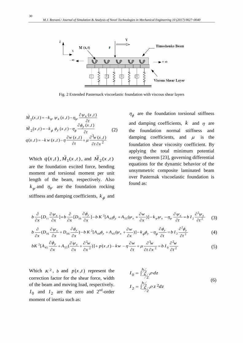
respectively. Fig. 2 depicts the generalized
Pasternak viscoelastic foundation with a
viscous shear layer. The transferred forces
and moments from the foundation the
beam can be calculated as [21]:
Fig. 1 A schematic of generally laminated composite beam
30
M.J. Rezvani./ Journal of Simulation & Analysis of Novel Technologies in Mechanical Engineering 10 (2017) 0027~0040
Fig. 2 Extended Pasternack viscoelastic foundation with viscous shear layers
1
2
3
2
( , )( , ) ( , )
( , )( , ) ( , )
( , ) ( , )( , ) ( , )
xx
yy
x tM x t k x t
tx t
M x t k x tt
w x t w x tq x t k w x t
t t x
(2)
Which ( , )q x t , 1( , )M x t , and 2 ( , )M x t
are the foundation excited force, bending
moment and torsional moment per unit
length of the beam, respectively. Also
k and are the foundation rocking
stiffness and damping coefficients, k and
are the foundation torsional stiffness
and damping coefficients, k and are
the foundation normal stiffness and
damping coefficients, and is the
foundation shear viscosity coefficient. By
applying the total minimum potential
energy theorem [23], governing differential
equations for the dynamic behavior of the
unsymmetric composite laminated beam
over Pasternak viscoelastic foundation is
found as:
11
22
5516 45 2 2[ ] [ ] [ ( )]
yx x xy x x
wb D b D b K A A k b I
x x x x x t t
(3)
2
216 66 44 45 2 2
( ) [ ( )]y y yx
y x y
wb D D b K A A k b I
x x x x t t
(4)
25545
2 3 2
02 2 2[ ( )] ( , )xy w w w w
bK A A p x t kw b Ix x x t t x t
(5)
Which 2K , b and ( , )p x t represent the
correction factor for the shear force, width
of the beam and moving load, respectively.
0I and 2I are the zero and 2nd
-order
moment of inertia such as:
20
2
222
2
h
h
h
h
I dz
I z dz
(6)

31
M.J. Rezvani./ Journal of Simulation & Analysis of Novel Technologies in Mechanical Engineering 10 (2017) 0027~0040
Which as the density of the composite
beam, ijA and ijD are the components of
the extensional and bending stiffness
matrices which are given as [23]:
1
1
)(
1
)( )( 5,4,k
k k
kk
ij
k
kijij
z
zjiQQA
NN
tdz (7)
( )
1
2
2, 1, 2, 6
12
( ) ( )
N
k
ij ij
k
k
k kD Q i jt
t z (8)
The ( )kijQ represents the reduced
transformed stiffness of the th
k layer
which are calculated as [23]:
224
22661211
411 )( 42
Q
QQQQ
n
nmm
(9)
1244
2266221112
)(
)( 4
Q
QQQQ
nm
nm
224
22661211
422 )( 42
Qm
nmn QQQQ
3
16 11 12 66
3
12 22 66
( 2 )
( 2 )
Q Q Q Q
Q Q Q
m n
n m
3662212
366121126
)(
)(
2
2
nm
mn
QQQ
QQQQ
)4466
226612221166
(
)( 22
mn
nm
Q
QQQQQ
552
442
44 QQQ nm
mnQQQ )( 445545
442
552
55 QQQ nm
Which m Cos , n Sin and ijQ are
known in terms of the engineering
constants and can be written as [23]:
2112
212
2112
12112
2112
111
11
1
EE
E
Q
Q
222
12 21
55 13
44 23
66 12
1
Q
Q G
Q G
Q
E
G
(10)
In order to calculate the beam steady-state
response, a new parameter s which
represents the position of the moving load
with respect to the x direction, is defined as
follows:
vtxs (11)
After implementing the following
differentiation chain rules:
3 3
2 3
2 22
2 2
2 2
2 2
( ( , )) ( ( ))
( ( , )) ( ( ))
( ( , )) ( ( ))
( ( , )) ( ( ))
( ( , )) ( ( ))
df x t v f s
t x ds
df x t v f s
t ds
df x t v f s
t ds
df x t f s
x ds
df x t f s
x ds
(12)
On Eqs. (3-5), one can get:
22
1 2 3 42 2
5 6 0
y
yxx
x
ddC C C C
ds ds
d dwC C
ds ds
(13)

32
M.J. Rezvani./ Journal of Simulation & Analysis of Novel Technologies in Mechanical Engineering 10 (2017) 0027~0040
22
7 8 9 102 2
11 12 0
yxx y
y
ddC C C C
ds ds
d dwC C
ds ds
3 2
13 14 15 163 2
17 18 ( )
y x
d w d w dwC C C C w
ds ds ds
d dC C F s
ds ds
The constant coefficients of 1C to 18C are
given in appendix A.
3- Solution of Governing Differential
Equations
To facilitate solution of motion’s
differential equations the complex Fourier
Transform and its inverse defined as [24]:
( ) ( )
1( ) ( )
2
isq
isq
F q f s ds
f s F q dq
e
e
(14)
After implementing the Fourier transform
on Eq. (13), the complex Fourier
Transforms of ( )w q , ( ) x q and ( )y q
are obtained as:
21 2 3
7 6 5 4 3 212 13 14 15 16 17 18 19
( ) ( )( )x
q iB q B q iB F qq
iB q B q iB q B q iB q B q iB q B
(15) 2
4 5 6
7 6 5 4 3 212 13 14 15 16 17 18 19
( ) ( )( )y
q iB q B q iB F qq
iB q B q iB q B q iB q B q iB q B
4 3 27 8 9 10 11
7 6 5 4 3 212 13 14 15 16 17 18 19
( ) ( )( )
B q iB q B q iB q B F qw q
iB q B q iB q B q iB q B q iB q B
Which the coefficients of 1B to 19B are
given in Appendix B. By performing the
inverse Fourier transform on Eq. (15),
( )x s , )(sy and ( )w s become:
19182
173
164
155
146
137
12
322
1
~~~~~~~~)()
~~~(
2
1)(
BqBqBqBqBqBqBqB
dqqFBqBqBiqs
iiii
ix
19182
173
164
155
146
137
12
652
4
~~~~~~~~)()
~~~(
2
1)(
BqBqBqBqBqBqBqB
dqqFBqBqBiqs
iiii
iy
(16)
19182
173
164
155
146
137
12
11102
93
84
7
~~~~~~~~)()
~~~~~(
2
1)(
BqBqBqBqBqBqBqB
dqqFBqBqBqBqBsw
iiii
ii
4-Results and Discussion
In this section, numerical results are
presented for an unsymmetrical laminated
composite beam 0 / 45 / 45 / 90 . In this
example we will demonstrate the

33
M.J. Rezvani./ Journal of Simulation & Analysis of Novel Technologies in Mechanical Engineering 10 (2017) 0027~0040
importance of the bend-twist coupling term
in such beam. Table 1 shows the different
property details of the T300/5208
composite beam [23] and Pasternak
viscoelastic foundation [21].
Table 1 Different property details of the composite T300/5208 beam and Pasternak viscoelastic foundation [21,
23]
Geometrical data for the
composite layers
Mechanical properties of
composite beam
Mechanical properties of Pasternak
viscoelastic foundation
Number of layers ( 4N ) 31540 /kg m 13.8k MN
Width the beam ( 5b cm ) 1 132E Gpa 5520 .N s
The thickness of the beam
( 10h cm ) 2 10.8E Gpa 13.8k MN
Angle-ply laminated beam
0 / 45 / 45 / 90 12 5.65G Gpa 5520 .N s
Correction factor for shear force
5 / 6K 13 23 3.38G G Gpa 69 .kN s
Magnitude load velocity
40 /v m s 12 0.24v 69k Mpa
Magnitude of the moving load
F(s) 144600 ( )s 13 23 0.59v v 2138 . /kN s m
In this study, the results are compared with
the analytical results an isotropic Euler-
Bernoulli beam under moving load
obtained by Fryba [25]. For this purpose,
the shear viscosity coefficient, foundation
rocking stiffness, damping coefficients and
normal damping coefficient in our analysis
are neglected. By setting these coefficients
equal to zero in Eqs. (3) and (5), one deals
with a beam supported by a Winkler elastic
foundation.
2
2
2
552
11 )(][
tIb
x
wAKb
xD
xb
x
xx
(17)
2
2
0
552 ),()]([
t
wIbkw
txpx
wAK
xb x
(18)
By substituting x
wx
, EID 11 ,
GAA 55
, II 2
, AI 0
and 2 *K k
and neglect the effect of rotary inertia in
Eqs. (17) and (18(, the governing
differential equations for the dynamic
behavior of isotropic Euler-Bernoulli beam
over elastic foundation is found as:
4 2
4 2( , )
w wEI A kw p x t
x x
(18)
This equation is exactly the same as the
one given in the literature for the dynamic
response of an isotropic Euler-Bernoulli
beam supported by a Winkler elastic
foundation under the motion of a traveling
load [25]. After implementing the Fourier
transform on Eq. (19), primarily the
displacement and subsequently the bending
moment and shear force can be calculated.
The variation of w, xM and xQ versus s
are plotted in Fig. 3. It has to be mentioned
that the plots in the Fig. 3 are similar to
those presented in Ref [16].

34
M.J. Rezvani./ Journal of Simulation & Analysis of Novel Technologies in Mechanical Engineering 10 (2017) 0027~0040
Fig. 3 Deflection, bending moment and shear force
for isotropic Euler-Bernoulli beam over a Winkler
elastic foundation [25]
4-1-Comparison between symmetric and
unsymmetric laminated composite beam
In this section, by using the data of given
in Table 1, the values of w , x and y are
solved for two cases of the symmetric
(0/90/90/0) and the unsymmetric (0/45/-
45/90) configurations [19]. Then, by
employing Eqs. (15-17), the shear force,
bending moment and bending stress are
accordingly obtained. The results for
deflection, shear force, bending moment
and bending stress distribution of
symmetric and unsymmetric composite
laminated beam are presented vs. s, the
distance from the position of the moving
load in Figs. (4-7). As it is evident from
Fig. 4, there is almost no difference
between the defection of symmetric and
unsymmetric laminated composite beam.
The variation of the shear force of
symmetric and unsymmetric laminated
composite beam is shown in Fig.5. As
shown in this figure, except point around
0s , interval the shear force values for two
beams are almost the same. Moreover,
there is a sign change for the shear force
for points before and after the point of load
exertion
Fig. 4 Comparison of deflection variation for
symmetric and unsymmetric composite beam
Fig. 5 Comparison of shear force distribution
between symmetric and unsymmetric composite
beam
Figure 6 shows the bending moment
distribution for symmetric and
unsymmetric laminated composite beam.
Contrary to two previous cases, this figure
depicts a clear difference between load
carrying capacity of unsymmetric laminate
composite beam and symmetric one.
However, in both beams the maximum
bending moment is located near to the
point where the point load is applied. It can
also be seen that the magnitude of the
bending moment in the unsymmetric
laminated composite beam is less than the
symmetric one.

35
M.J. Rezvani./ Journal of Simulation & Analysis of Novel Technologies in Mechanical Engineering 10 (2017) 0027~0040
Fig. 6 Bending moment vs. s distribution of a
symmetric and unsymmetric composite beam
Having the bending moment
distribution, one can easily obtain the
bending stress, x for symmetric and
unsymmetric laminated composite beam.
Fig.7 illustrates the bending stress
distribution on the upper layer. Having the
bending moment distribution, one can
easily obtain the bending stress, x for
symmetric and unsymmetric laminated
composite beam. Fig.7 illustrates the
bending stress distribution on the upper
layer.
Fig. 7 Bending stress vs. s distribution of a symmetric
and unsymmetric composite beam for the upper layer
4-2-Effects of different parameters on the beam
deflection
The maximum value of deflection of an
unsymmetric laminated composite beam
with varying of the foundation normal
stiffness, foundation viscosity and the
moving load velocity is shown in Fig 8. As
seen in this figure, by increasing the
foundation normal stiffness coefficient, the
maximum value of deflection decreases
and it moves towards the point where the
load is applied i.e. 0s . Also, by
increasing the foundation viscosity
coefficient and the moving load velocity,
the maximum value of deflection decreases
and it moves further away from the point
where the load is applied ( 0s ).
Fig. 8 Effects of different parameters on the maximum
value of the deflection
4-3-Effects of different parameters on the
shear force
The maximum value of the shear force of
an unsymmetric laminated composite beam
with varying of the foundation normal
stiffness, foundation viscosity and the
moving load velocity is shown in Fig 9. As
illustrated in this figure, the maximum
value of the shear force takes place right at
the point where the load is exerted i.e.
0s . Moreover, as foundation normal

36
M.J. Rezvani./ Journal of Simulation & Analysis of Novel Technologies in Mechanical Engineering 10 (2017) 0027~0040
stiffness coefficient, foundation viscosity
coefficient and the moving load velocity
increases, the maximum value of the shear
force decreases
Fig. 9 Effects of different parameters on the maximum
value of the shear force
4-4-Effects of different parameters on the
bending moment
Figure 10 shows the effects of different
parameters such as the foundation normal
stiffness coefficient, foundation viscosity
coefficient and the moving load velocity
on the maximum value of the bending
moment of an unsymmetric laminated
composite beam. As observed, by
increasing the foundation normal stiffness
coefficient, the maximum value of bending
moment moves closer to the point where
the load is applied ( 0s ). Whereas, by
increasing the foundation viscosity
coefficient and the moving load velocity,
the maximum value of the bending
moment decreases and the point of
maximum bending moment moves further
away from the load exertion point ( 0s ).
Also, when the foundation shear viscosity
coefficient and the moving load velocity
are zero, the bending moment diagram has
a maximum value at the point where the
moving load is applied ( 0s )
Fig. 10 Effects of different parameters on the
maximum value of the bending moment
4-5-Effects of different parameters on the
bending stress distribution
It is clear that in the laminated composite
beam the linear trend of normal stress
variation due to the bending moment does
not change in each layer. Therefore, to
investigate the effects of different
parameters on the normal stress
distribution of the entire cross section,
analysis was conducted only on the upper
layer of the beam. Figure 11 shows the
effects of different parameters such as the
foundation normal stiffness coefficient,
foundation viscosity coefficient and the
moving load velocity on x distribution of
the central line of upper layer of an
unsymmetric laminated composite beam.
As illustrated in the figure, by increasing
the value of k , the maximum value of the
stress decreases and it moves closer to the
point where the load is applied. As seen,
when the foundation shear viscosity
coefficient and the moving load velocity

37
M.J. Rezvani./ Journal of Simulation & Analysis of Novel Technologies in Mechanical Engineering 10 (2017) 0027~0040
are zero, the value of stress x are
maximum at the moving load exertion
point. By increasing the foundation
viscosity coefficient and the moving load
velocity, this maximum point moves
behind of the load exertion point and the
value of stress x decreases.
Fig. 11 Effects of different parameters on the x
distribution
5-Conclusions
In this study, the behaviour of an
unsymmetric laminated composite beam
over Pasternak viscoelastic foundation
under travelling concentrated load was
analyzed. For this purpose, by employing
the first order shear deformation theory
and using the principle of total minimum
potential energy, the governing differential
equations of motion were obtained. The
complex infinite Fourier transformation
method applied as well and the obtained
analytically parameter values of deflection,
bending moment, shear force and the
bending stress. Based on this analysis the
following were concluded:
1. By increasing the foundation normal
stiffness coefficients, the maximum value
of beam deflection, bending moment and
stress decreased and the maximum value of
deflection was approached closer to the
moving load exertion point.
2. By increasing the foundation viscosity
coefficient and the moving load velocity,
the maximum value of deflection, bending
moment and the stress decreased and it was
moved further away from the point where
the load was applied.
3. The maximum value of the bending
moment and the stress occurred when the
foundation viscosity coefficient and the
moving load velocity were zero and it
takes placed right at the point where the
load was exerted i.e. 0s .
4. By increasing the foundation normal
stiffness coefficient, foundation viscosity
coefficient and the moving load velocity,
the maximum value of the shear force
decreased and it takes placed right at the
point where the load was exerted i.e. 0s .
All of the obtained results may be useful
for design purposes and a better
understanding of the behavior of the
structural systems of railways under
moving loads.
Appendix
Appendix A
Parameters of Eq. (13)
kAbKC 44102
2
2111 vIbDbC
vC 11 162 bDC
45
2
12 AbKC kAbKC 55
2
3
vC 13 45
2
4 AbKC
2
55
2
014 vIbAbKC vC 5
vC 15 55
2
6 AbKC
kC 16 167 bDC
45
2
17 AbKC 2
2668 vIbDbC
55
2
18 AbKC 45
2
9 AbKC

38
M.J. Rezvani./ Journal of Simulation & Analysis of Novel Technologies in Mechanical Engineering 10 (2017) 0027~0040
Appendix B
Parameters of Eq. (15)
871221 66~
CCCCCCB
1162~
CCB
101293 646~
CCCCCCB
1214~
CCB
5125
~CCB
3126
~CCB
71817
~CCCCB
11157588
~CCCCCCB
7383911011159
~CCCCCCCCCCB
1135951010
~CCCCCCB
9331011
~CCCCB
8131713112
~CCCCCCB
71417135111318141813513
~CCCCCCCCCCCCCCCB
14 3 13 8 3 13 7 1 13 9 1 15 8 5 13 11 5 14 8 5 14 7 1 14 11 1 15 7 1 13 10 B C C C C C C C C C C C C C C C C C C C C C C C C C C C C C C
1 5 5 1 3 1 0 1 1 7 1 1 5 1 1 1 1 8 3 1 3 1 1 3 1 4 8 1 1 7 1 2 3 1 4 7
2 1 2 1 8 6 7 1 8 1 1 4 1 0 6 8 1 8 5 1 3 9 5 1 4 1 1 5 1 5 8 5 1 5 7 1 1 4 9
6 6
B C C C C C C C C C C C C C C C C C C C C C C C C
C C C C C C C C C C C C C C C C C C C C C C C C C C C
1 3 1 4 1 1 3 1 5 8 3 1 5 7 5 1 5 1 1 5 1 6 8 5 1 4 9 5 1 6 7 5 1 7 1 2
3 1 3 1 0 3 1 3 9 1 1 5 1 0 1 1 6 1 1 5 1 4 1 0 1 1 5 9 6 1 1 1 8
6
B C C C C C C C C C C C C C C C C C C C C C C C C
C C C C C C C C C C C C C C C C C C C C C
1 7 5 1 5 9 5 1 6 1 1 3 1 6 7 3 1 6 8 3 1 7 1 2 1 1 6 1 0 1 1 6 9
3 1 4 1 0 3 1 4 9 3 1 3 1 1 9 1 8 4 1 2 1 8 6 1 0 1 8 5 1 5 1 06
B C C C C C C C C C C C C C C C C C C C C C
C C C C C C C C C C C C C C C C C C C C C
9151015111391531015318 666~
CCCCCCCCCCCCCCCB
1013916319 6~
CCCCCCB
References
[1] D. G. Duffy, "The response of an
infinite railroad track to a moving,
vibrating mass," Journal of Applied
Mechanics, vol. 57, pp. 66-73, 1990.
[2] C. Cai, Y. Cheung, and H. Chan,
"Dynamic response of infinite continuous
beams subjected to a moving force—an
exact method," Journal of Sound and
Vibration, vol. 123, pp. 461-472, 1988.
[3] S. Mackertich, "The response of an
elastically supported infinite Timoshenko
beam to a moving vibrating mass," The
Journal of the Acoustical Society of
America, vol. 101, pp. 337-340, 1997.
[4] V.-H. Nguyen and D. Duhamel,
"Finite element procedures for nonlinear
structures in moving coordinates. Part II:
Infinite beam under moving harmonic
loads," Computers & Structures, vol. 86,
pp. 2056-2063, 2008.

39
M.J. Rezvani./ Journal of Simulation & Analysis of Novel Technologies in Mechanical Engineering 10 (2017) 0027~0040
[5] S. P. Patil, "Response of infinite
railroad track to vibrating mass," Journal
of engineering mechanics, vol. 114, pp.
688-703, 1988.
[6] R. U. A. Uzzal, R. B. Bhat, and W.
Ahmed, "Dynamic response of a beam
subjected to moving load and moving mass
supported by Pasternak foundation," Shock
and Vibration, vol. 19, pp. 205-220, 2012.
[7] H. Ding, K.-L. Shi, L.-Q. Chen,
and S.-P. Yang, "Dynamic response of an
infinite Timoshenko beam on a nonlinear
viscoelastic foundation to a moving load,"
Nonlinear Dynamics, vol. 73, pp. 285-298,
2013.
[8] A. Mallik, S. Chandra, and A. B.
Singh, "Steady-state response of an
elastically supported infinite beam to a
moving load," Journal of Sound and
Vibration, vol. 291, pp. 1148-1169, 2006.
[9] S. Lu and D. Xuejun, "Dynamic
analysis to infinite beam under a moving
line load with uniform velocity," Applied
mathematics and mechanics, vol. 19, pp.
367-373, 1998.
[10] A. D. Kerr, "Elastic and
viscoelastic foundation models," Journal
of Applied Mechanics, vol. 31, pp. 491-
498, 1964.
[11] Y.-H. Chen, Y.-H. Huang, and C.-
T. Shih, "Response of an infinite
Timoshenko beam on a viscoelastic
foundation to a harmonic moving load,"
Journal of Sound and Vibration, vol. 241,
pp. 809-824, 2001.
[12] L. Sun, "A closed-form solution of
a Bernoulli-Euler beam on a viscoelastic
foundation under harmonic line loads,"
Journal of Sound and vibration, vol. 242,
pp. 619-627, 2001.
[13] S. Verichev and A. Metrikine,
"Instability of a bogie moving on a flexibly
supported Timoshenko beam," Journal of
sound and vibration, vol. 253, pp. 653-668,
2002.
[14] T. Liu and Q. Li, "Transient elastic
wave propagation in an infinite
Timoshenko beam on viscoelastic
foundation," International journal of solids
and structures, vol. 40, pp. 3211-3228,
2003.
[15] M. Kargarnovin and D. Younesian,
"Dynamics of Timoshenko beams on
Pasternak foundation under moving load,"
Mechanics Research Communications, vol.
31, pp. 713-723, 2004.
[16] M. Kargarnovin, D. Younesian, D.
Thompson, and C. Jones, "Response of
beams on nonlinear viscoelastic
foundations to harmonic moving loads,"
Computers & Structures, vol. 83, pp. 1865-
1877, 2005.
[17] G. Muscolino and A. Palmeri,
"Response of beams resting on
viscoelastically damped foundation to
moving oscillators," International Journal
of Solids and Structures, vol. 44, pp. 1317-
1336, 2007.
[18] F. F. Çalım, "Dynamic analysis of
beams on viscoelastic foundation,"
European Journal of Mechanics-A/Solids,
vol. 28, pp. 469-476, 2009.
[19] M. Kadivar and S. Mohebpour,
"Finite element dynamic analysis of
unsymmetric composite laminated beams
with shear effect and rotary inertia under
the action of moving loads," Finite
elements in Analysis and Design, vol. 29,
pp. 259-273, 1998.
[20] M. Rezvani and K. M.
Khorramabadi, "Dynamic analysis of a
composite beam subjected to a moving
load," Proceedings of the Institution of
Mechanical Engineers, Part C: Journal of
Mechanical Engineering Science, vol. 223,
pp. 1543-1554, 2009.
[21] M. J. Rezvani, M. H. Kargarnovin,
and D. Younesian, "Dynamic analysis of
composite beam subjected to harmonic
moving load based on the third-order shear
deformation theory," Frontiers of
Mechanical Engineering, vol. 6, pp. 409-
418, 2011.
[22] H. Abramovich and A. Livshits,
"Free vibrations of non-symmetric cross-
ply laminated composite beams," Journal
of sound and vibration, vol. 176, pp. 597-
612, 1994.

40
M.J. Rezvani./ Journal of Simulation & Analysis of Novel Technologies in Mechanical Engineering 10 (2017) 0027~0040
[23] J. N. Reddy, Mechanics of
laminated composite plates and shells:
theory and analysis: CRC press, 2004.
[24] A. David Wunsch, "Complex
Variables With Applications [M]," ed:
Reading, Mass: Addison-Wesley
Publishing Company, 1994.
[25] L. Fryba, Vibration of solids and
structures under moving loads: Thomas
Telford, 1999.