structural behavior of anchored structural behavior of anchored plates in tilt-up construction
TRANSCRIPT
Structural Behavior of AnchoredStructural Behavior of Anchored Plates in Tilt-up Construction
Presented byUlric Ibanez, REU StudentBill Sheu, Graduate Mentor Y. L. Mo, Faculty Advisor
August 2010
CONTENTS
1. Introduction
2. Literature Review
3. Experimental Program
4 E i t l R lt4. Experimental Results
5. Conclusion and Future Work
It all started with a flowerpot
Tilt-Up Construction
• It all started with a flowerpot.
• French gardener, Joseph Monier put iron mesh to reinforce garden pots and tubs in 1849.
• The father of tilt-up concrete, Robert Aiken poured the walls flat on a sand bed with door and window openings and then tipped them up onto the foundation in 1906foundation in 1906.
• Robert Aiken later refined his method, using a steel tipping table to build 15 buildings, which included a two-story ammunition house.
• Thomas Edison built an entire village of tilt-up concrete houses in Union, New Jersey in 1908.
• After the development of the mobile crane, the tilt-up wall started gaining popularity.
Tilt-Up Construction
• Tilt-Up concrete construction began in California in the late 1950s and later spread out to construction industrial throughout United States.
• This construction method is cost-saving, fast, and safe; the tilt-up building is durable and has decent fire and seismic resistance.
• The tilt-up wall panels act as load-bearing walls and can also serve as curtain walls for the exterior face of building. g
• The wall panels can be customized for different colors, textures, exposed aggregates, from liners or to any custom appearances ;exposed aggregates, from liners or to any custom appearances ; They can also be designed as sandwich thermal panels.
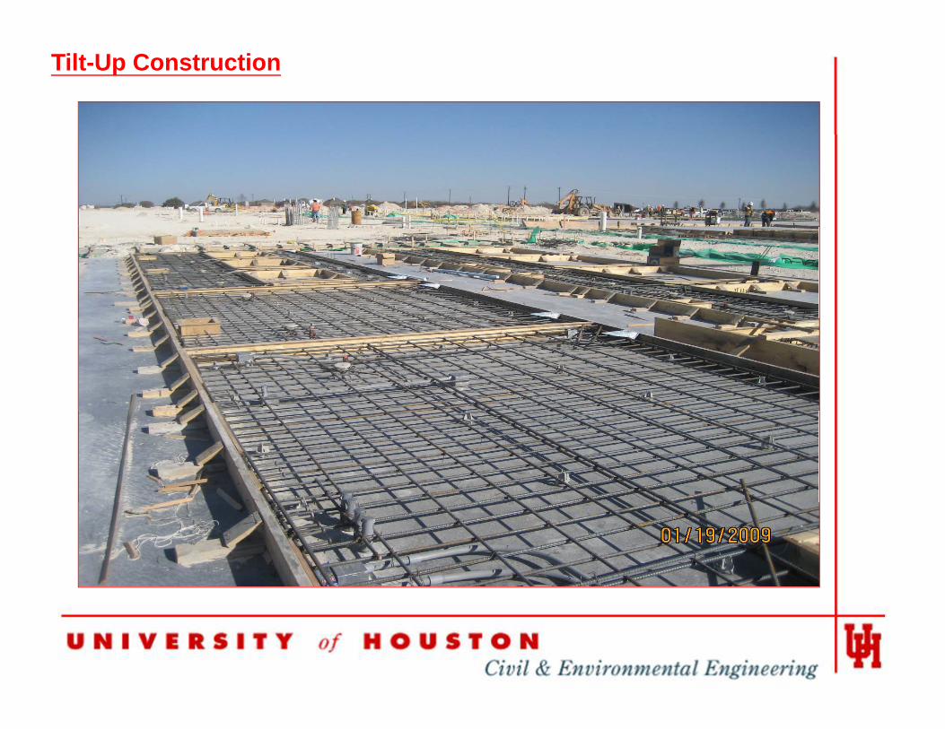
Tilt-Up Construction
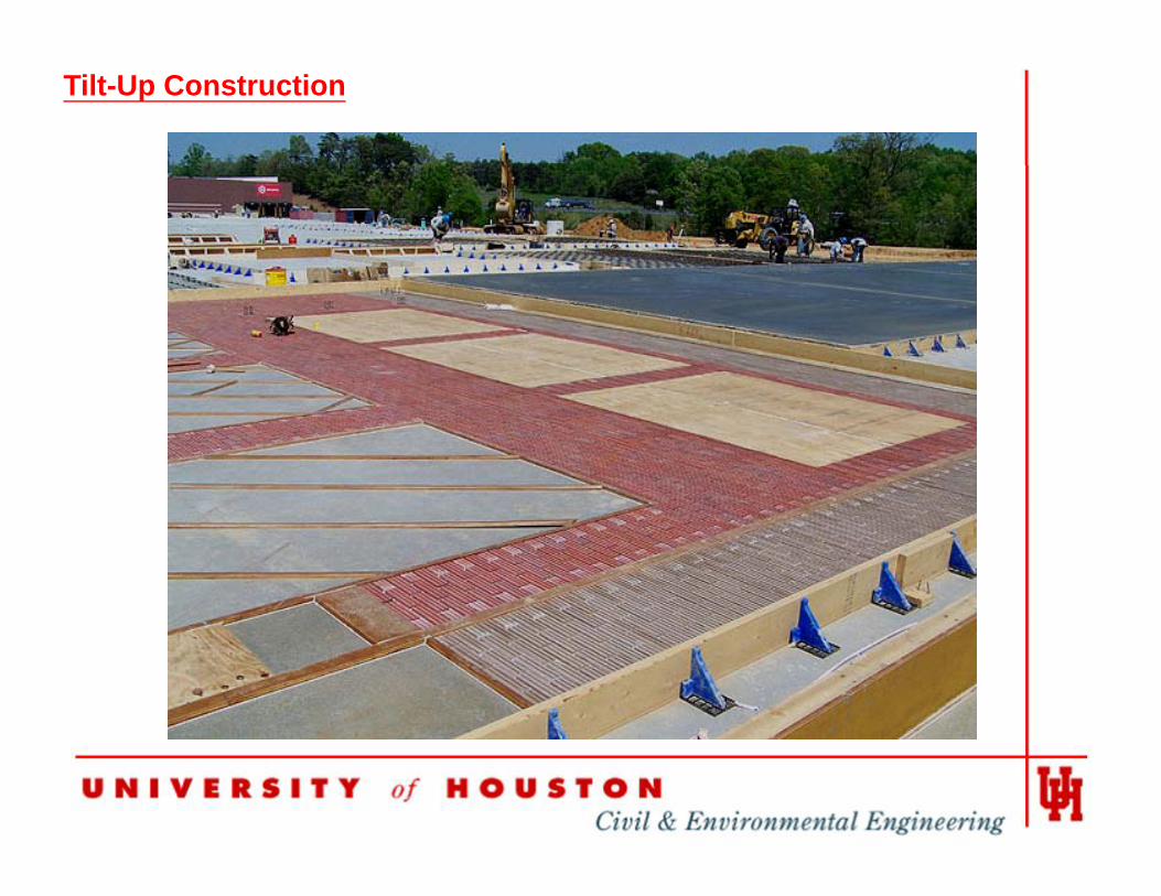
Tilt-Up Construction
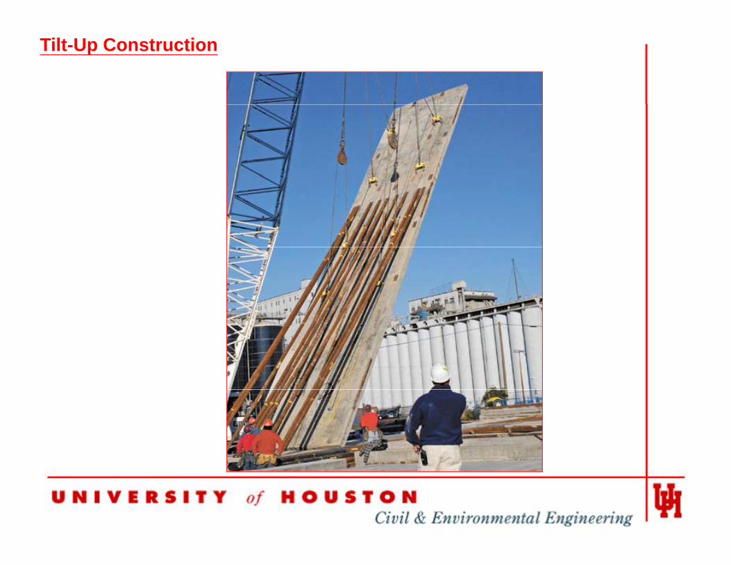
Tilt-Up Construction
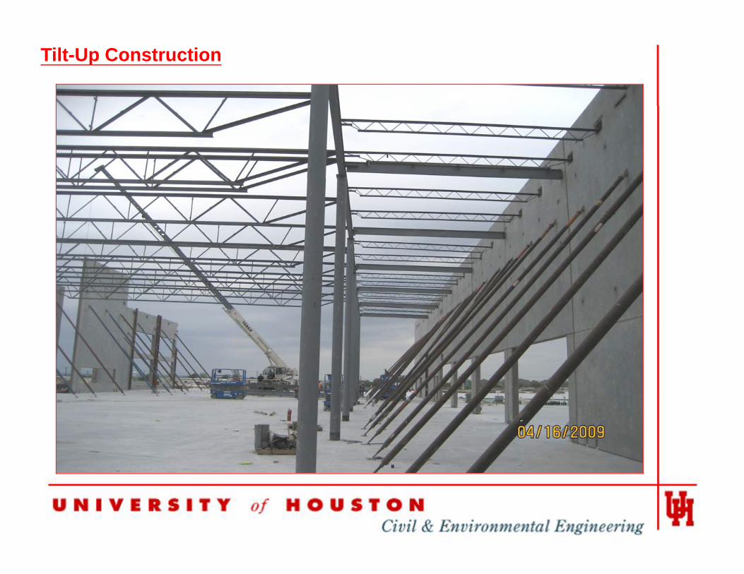
Tilt-Up Construction
Tilt-Up Construction
• According the Tilt-Up Concrete Association, over 15% industrial buildings between 5,000 to 1.5 million square foot are constructed with tilt-up wallsfoot are constructed with tilt-up walls.
• Each year at least 10,000 buildings enclosing 650 million ac yea at east 0,000 bu d gs e c os g 650 osquare foot are constructed by the tilt-up construction method.
• Tilt-up is particularly well-suited to warehouses, schools, offices, churches, shopping centers and manufacturing plants, or any other concrete buildings up to five floors in h i htheight .
Tilt-Up Construction
Tilt-Up Construction
Tilt-Up Construction
Connections for Tilt-Up Wall
• According to PCA, there are 28 connection details.
• They are many connections are used in tilt-up construction.
• The cast-in and post-in connections .
The most common cast in connection is embedded steel plate• The most common cast-in connection is embedded steel plate which made of a steel plate with weld-on headed studs.
Connections for Tilt-Up Wall
• The headed anchor is a plain shank with an oversized head for application with arc welding machine.
• The stud welding was developed in 1939 at New York Naval Ship yard for the purpose of attaching wood planking on the metal deck of navy aircraft carriers.planking on the metal deck of navy aircraft carriers.
• The head stud anchor can be displaced on steel channel and steel angle. After the arc-welding process had been used, g g pthe industry began to use stud-welding guns to save time, labor and cost.
Connections for Tilt-Up Wall
• The headed stud rapidly expanded internationally in all construct. Following the invention of the welding gun, the most common cast in connection has been a steel plate withmost common cast-in connection has been a steel plate with weld-on headed studs.
• The stud welded embedded steel plates are widely used in the tilt-The stud welded embedded steel plates are widely used in the tiltup construction industry because they have been proven to be more efficient and more economical than other methods.
• The tilt-up buildings are usually designed as box-type structures with the floors and roof acting as horizontal diaphragms. The diaphragms transfer the live load and dead load to tilt-up panels acting as load bearing walls.
Connections for Tilt-Up Wall
• The eccentric vertical loads from the floors and roof transfer through the embedded steel plate supports to tilt-up panels .p p
• The steel beams or steel girders can be welded directly to the cast-in embedded steel plate supports.
• The steel channels or steel tees will be welded to the cast-in embedded steel plate supports to support t l b j i t t l b t l i d d t lsteel bar joists, steel beams, steel girders ,and metal
decking.
• Most tilt up embed steel plate supports are under the• Most tilt-up embed steel plate supports are under the combination loading of shear and tension.
Headed Stud Embedded Steel Plate
• Anchor designers were using manufactures’ catalogs before the g g ganchors design requirements were added to ACI 318 -02 .
• ACI 318 Appendix D is based on the Concrete Capacity Design (CCD) method which was an adaptation of the original European Kappa method proposed by Eligehausen and Fuchs in the late 1980s.
PCI D i H db k h d t d d i it i i iti t d i• PCI Design Handbook head stud design criteria were initiated in response to the database dominated by test results of post-in anchor tests in ACI 318-02 .
• PCI Design Handbook Section 6.5 of sixth edition provided the design equations for headed-stud connections.
• Appendix B – Steel Embedment of ACI 349 for nuclear safety related concrete structures.
Problem Statement
• In the last twenty years the data and studies of embedded steel plate supports are rather scanty.
• Methods available: ACI 349’s method and CCD’s method, PCI C ti M lConnections Manual.
• According to Werner Fuchs et al. (1995), since ACI 349’s method is over conservative in some cases the CCD method isis over conservative in some cases, the CCD method is strongly recommended.
• The 40 percent difference in predicted strength versusThe 40 percent difference in predicted strength versus experimental results is consistent with previous research for anchors in cracked concrete by Kevin Lemieux et al. (1998).
• The ACI Appendix D is not appropriate for predicting headed studs pryout capacity according to Neal S. Anderson et al. (2005).
Problem Statement
• The capacity of embedded steel plate supports are affected by concrete strength, concrete sizes, steel plate, stud material, sizes of plate and stud, location of the studs andmaterial, sizes of plate and stud, location of the studs and plates, etc.
• In last six years, The author noticed that some embedded steel plates supports are overdesigned.
• Designers need more accurate and useable equations or standard sizes table for the tilt-up embedded steel plate supports design.
Solution
• Finite element analyses (ABAQUS) program models the behaviors of the embedded steel plate supports which are cast in the concrete under the applied load.cast in the concrete under the applied load.
• Embedded steel plate strength, concrete strength, plate size and thickness number of studs and locations stud diameter studthickness, number of studs and locations , stud diameter, stud length, and all other perimeters can be Implemented into the FEA program .
• The accuracy of the results from the FEA simulation models will be verified by the results from the Structure Laboratory testing at UHtesting at UH.
Solution
• The ABAQUS program will be used to create a standard sizes of embedded plate supports for tilt-up construction.
• The steel companies can manufacture and stock the standard size embedded plate supports for tilt-up contractors.
• The design requirements and specifications of the embedded steel plate will have engineer oversight.
3. Experimental Program
3.1 Facilities3.2 Specimens3 3 Experimental Setup3.3 Experimental Setup 3.4 Test Procedure 3.5 Test Results
Facilities
• The tests were performed in the Structures Laboratory at UH.
• Equipments : Universal Panel Tester (UPT), custom made steel form , concrete ready mixer.
• Six different configuration anchor plates provided by CMC Construction Services(CMCCS) have been tested.
• The 55”x55”x7” concrete panels were poured each with steel plate was cast in.
Facilities
• The Ready Mix Concrete donated by CMCCS meets or exceeds 4000psi.
• A custom made 36”x3” diameter solid steel rod was attached to the top center actuator on the UPT to provide concentrated load.
• A “O-shaped” ring is welded on the top of the angle to guide the loading rod. This allows for application of a concentrated load, preventing lateral shifting and bending.p g g g
• Two LVDT sensors are attached to the angle to monitor the deflection of the embedded plate.
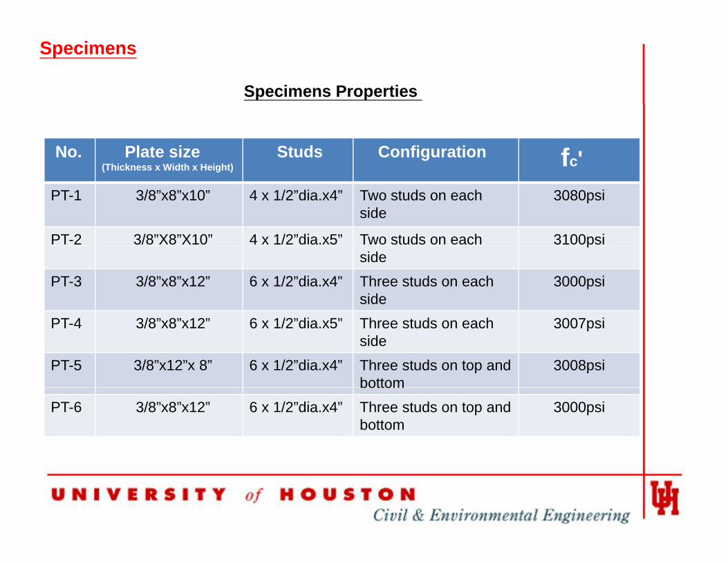
Specimens Properties
Specimens
No. Plate size(Thickness x Width x Height)
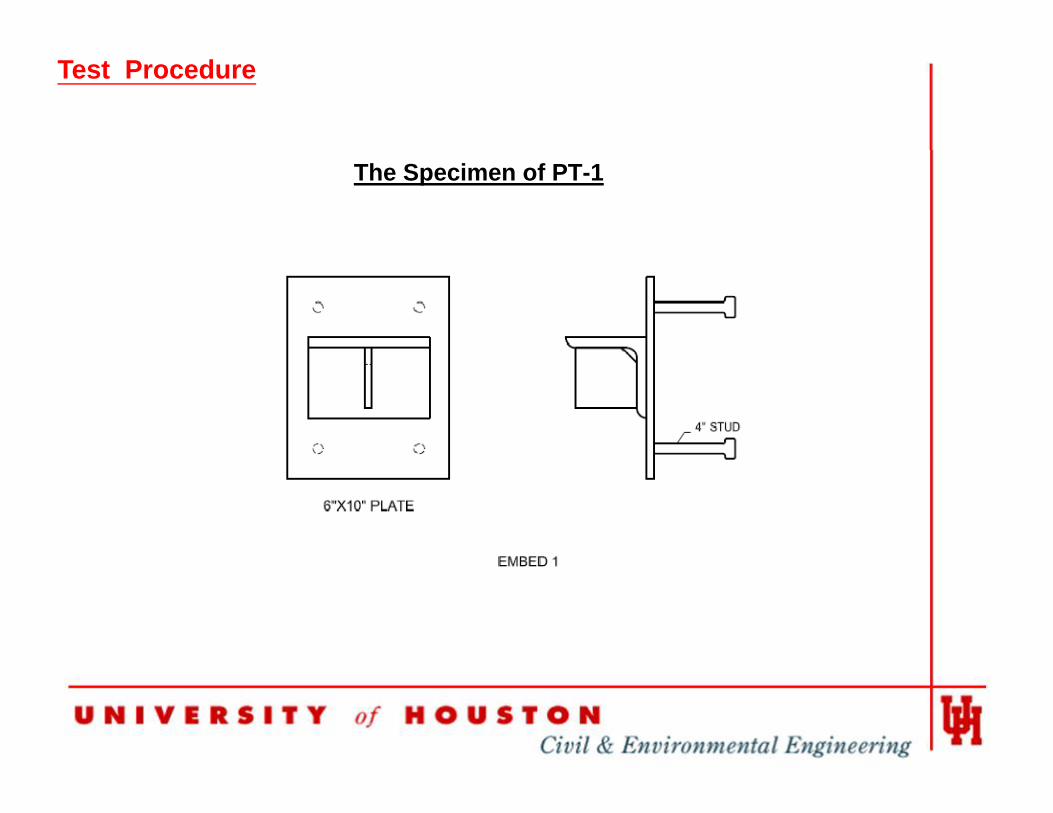
Studs Configuration fc'PT-1 3/8”x8”x10” 4 x 1/2”dia.x4” Two studs on each
side3080psi
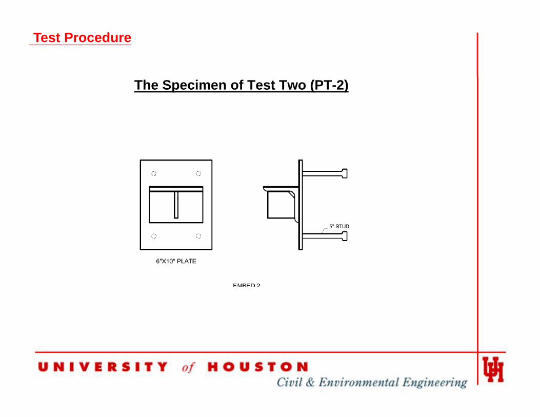
PT-2 3/8”X8”X10” 4 x 1/2”dia.x5” Two studs on each 3100psiside
p
PT-3 3/8”x8”x12” 6 x 1/2”dia.x4” Three studs on each side
3000psi
PT-4 3/8”x8”x12” 6 x 1/2”dia.x5” Three studs on each side
3007psi
PT-5 3/8”x12”x 8” 6 x 1/2”dia.x4” Three studs on top and bottom
3008psibottom
PT-6 3/8”x8”x12” 6 x 1/2”dia.x4” Three studs on top and bottom
3000psi
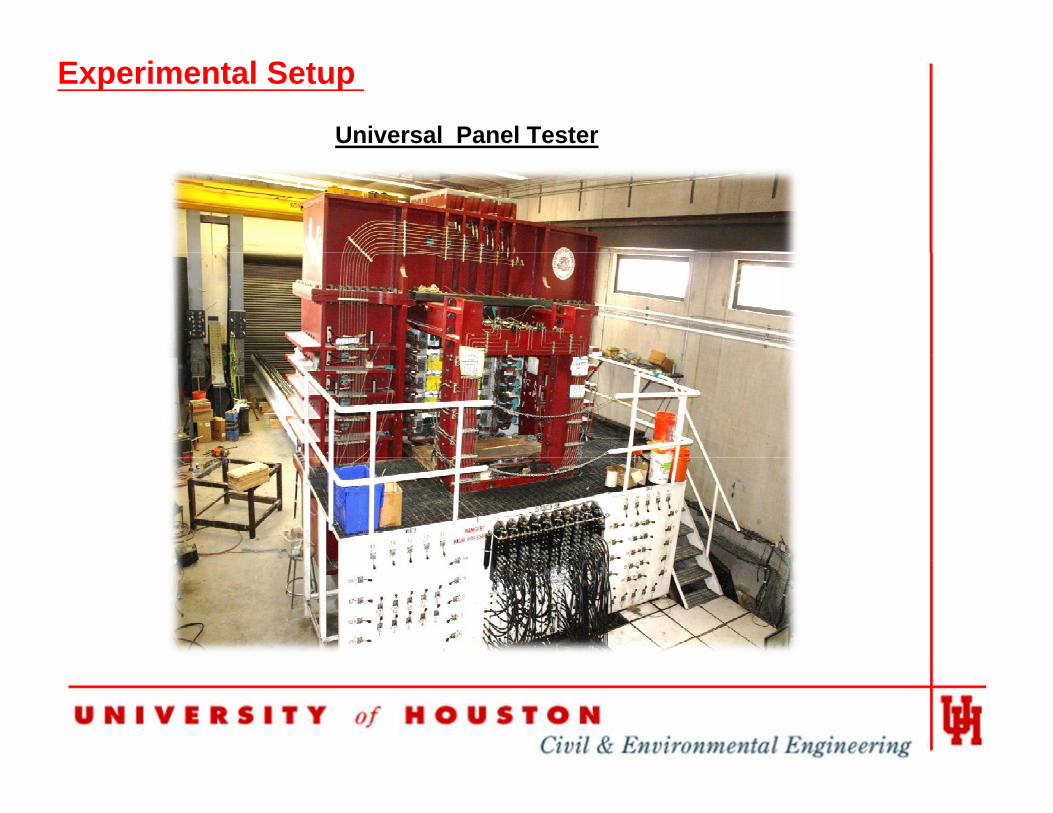
Universal Panel Tester
Experimental Setup
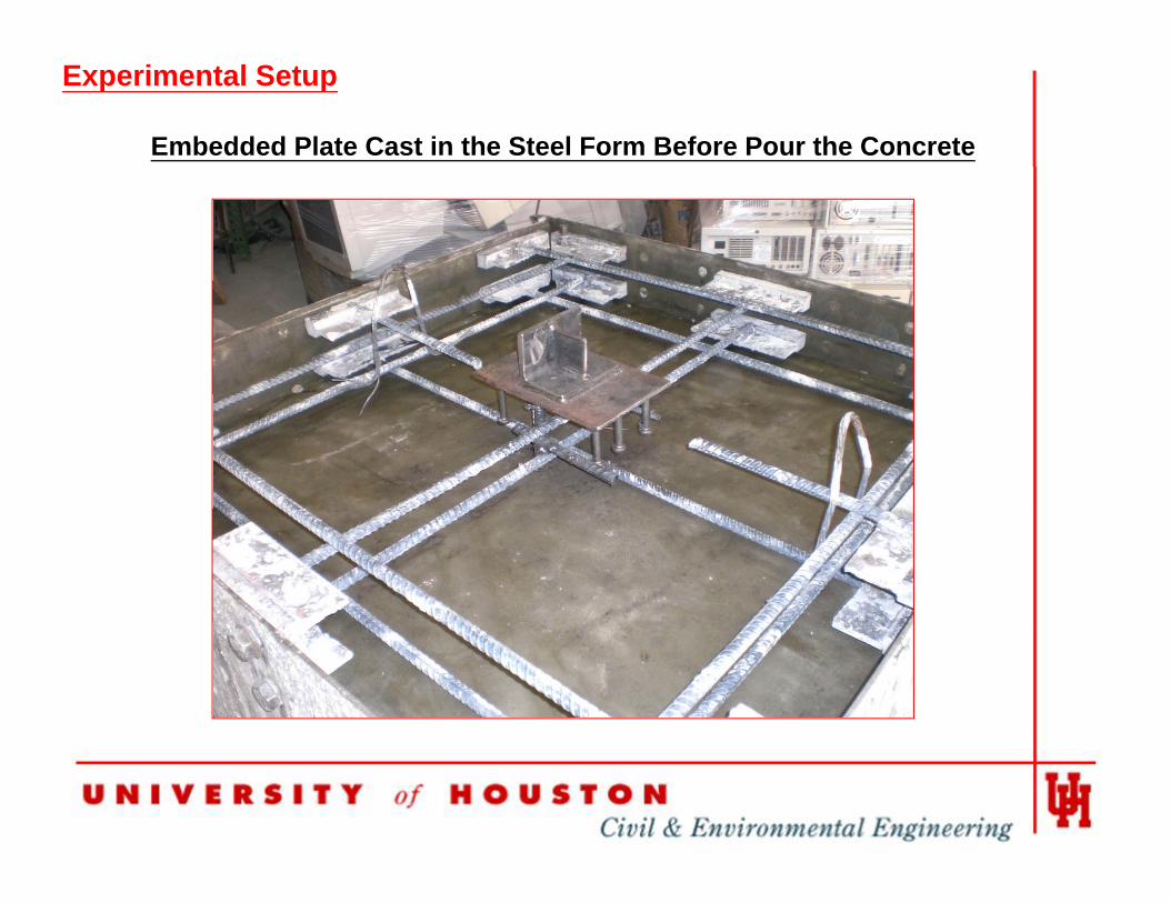
Embedded Plate Cast in the Steel Form Before Pour the Concrete
Experimental Setup
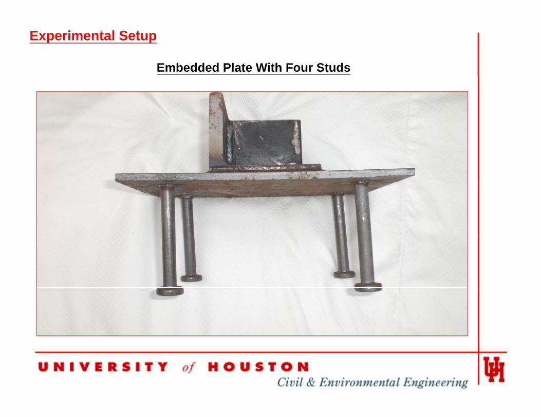
Embedded Plate With Four Studs
Experimental Setup
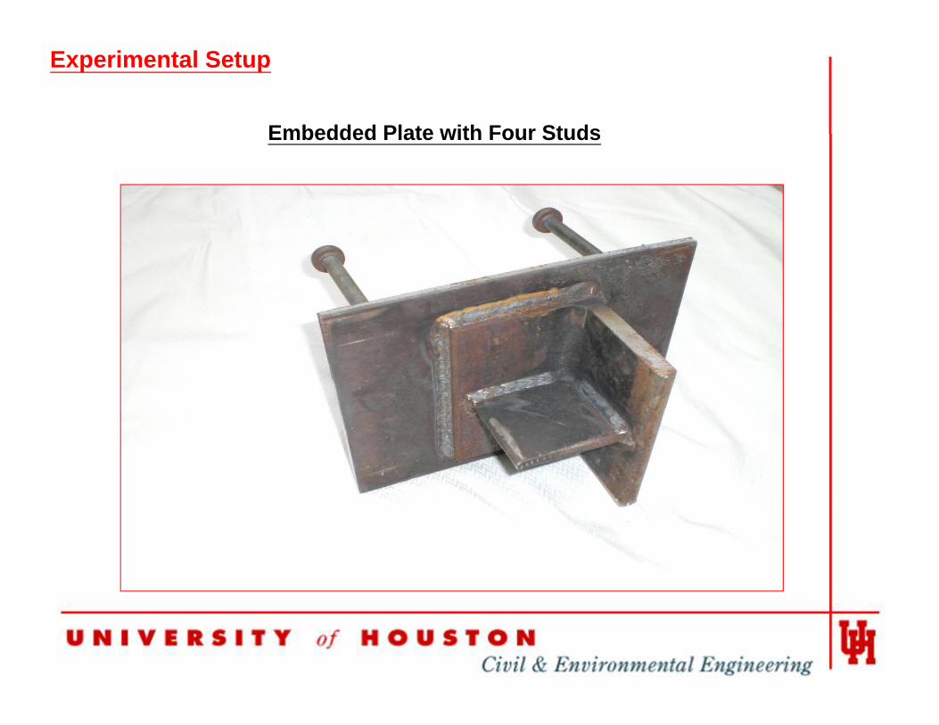
Embedded Plate with Four Studs
Experimental Setup
Embedded Plate with Four Studs
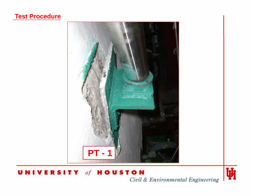
Test Procedure
The Specimen of PT-1
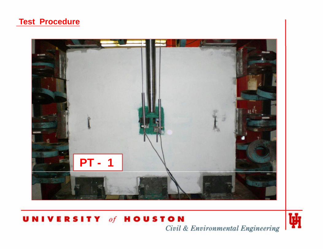
Test Procedure
PT - 1
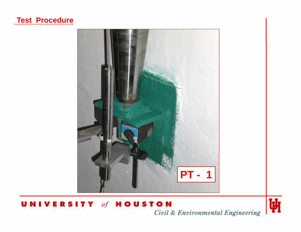
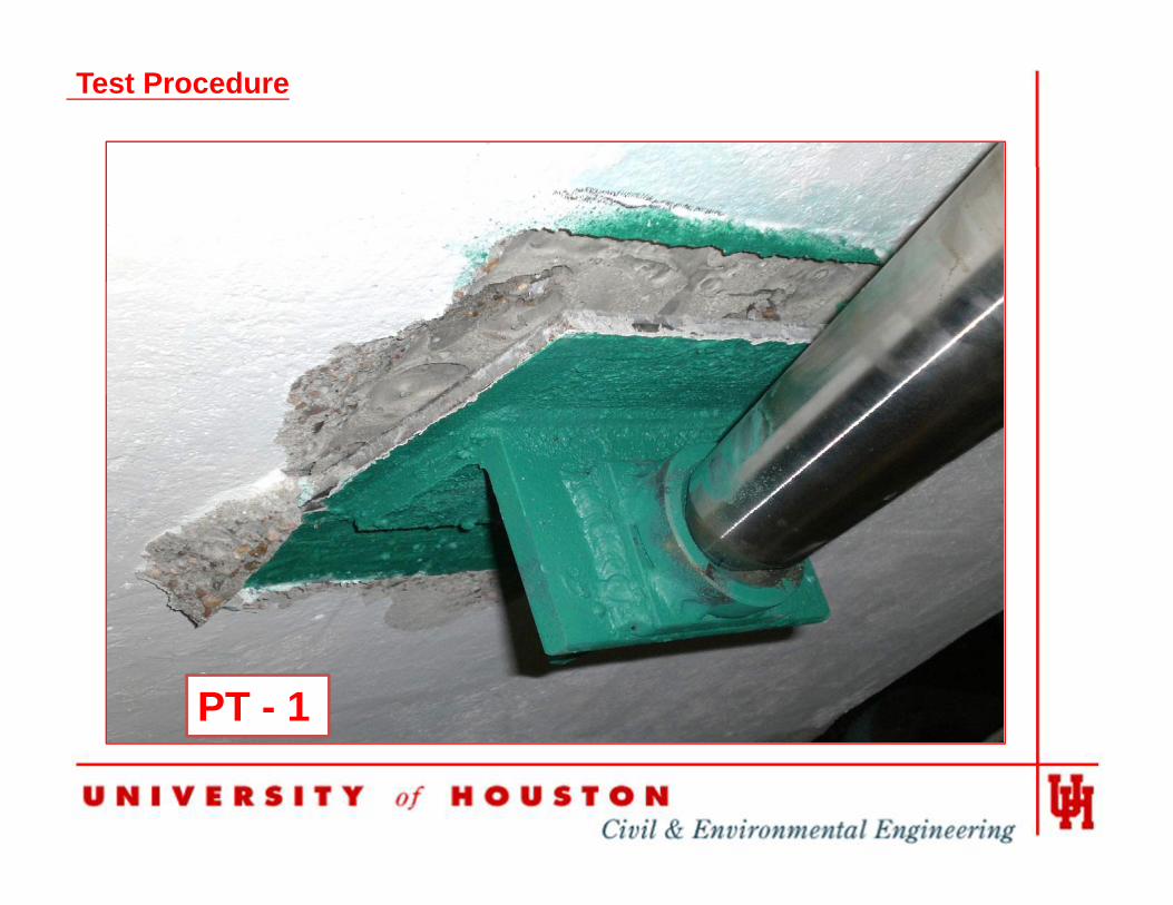
Test Procedure
PT - 1
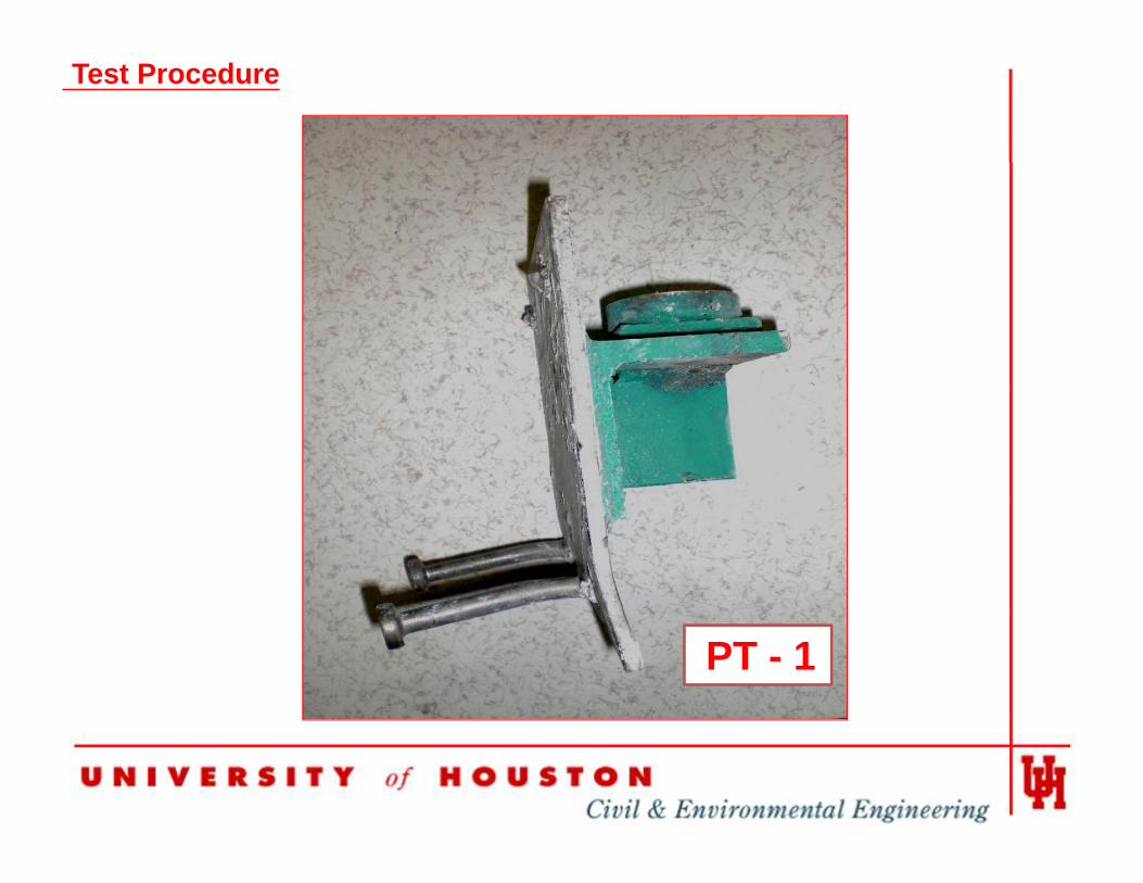
Test Procedure
PT - 1
Test Procedure
PT - 1
Test Procedure
PT - 1
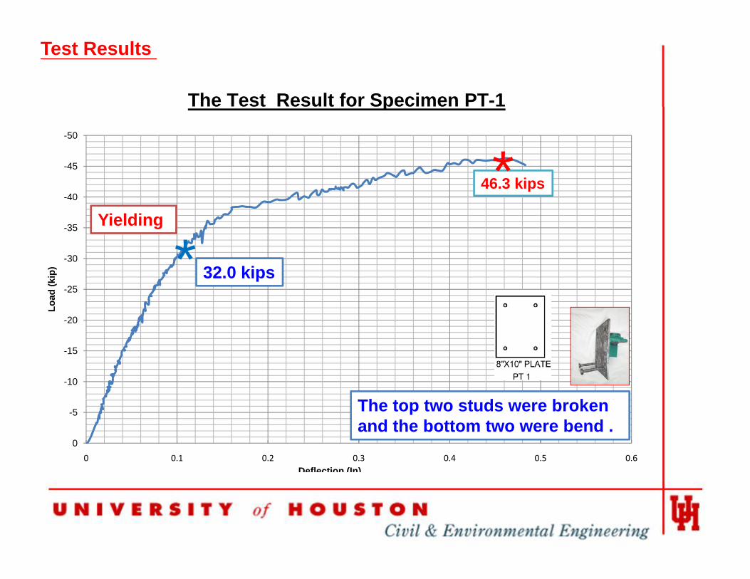
The Test Result for Specimen PT-1
Test Results
p-50
-45
46 3 ki*-40
-35
46.3 kips
*Yielding
-30
-25
-20
Load
(kip
) * 32.0 kips
-15
-10
Th d b k-5
00 0.1 0.2 0.3 0.4 0.5 0.6
Deflection (In)
The top two studs were broken and the bottom two were bend .
Test Procedure
The Specimen of Test Two (PT-2)
Test Procedure
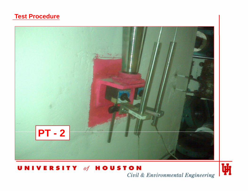
PT 2PT - 2
Conclusions
• Embedded steel plates are overdesigned .
Si t l i t t d til f il i UPT• Six concrete panel specimens were tested until failure using UPT.

AcknowledgementsAcknowledgementsThe research study described herein was sponsored by the National Sciencesponsored by the National Science Foundation under the Award No. EEC-0649163. The opinions expressed in this study are those of the authors and do not necessarily reflect the views of the sponsor.sponsor.