structure analysis of simmmons college school of...
TRANSCRIPT
STRUCTURE ANALYSIS OF SIMMONS COLLEGE SCHOOL
OF MANAGEMENT
Fang Xu , Kara Wetzel , Kevin Walsh, Yuting Song
General Building Data
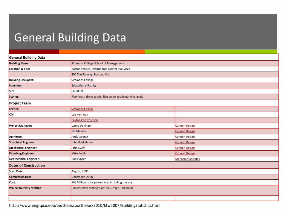
General Building Data
Building Name: Simmons College School of Management
Location & Site: Boston Proper, Institutional Master Plan Area
300 The Fenway, Boston, Ma
Building Occupant: Simmons College
Function: Educational Facility
Size: 66,500 sf
Stories: Five floors above grade, five below grade parking levels
Project Team
Owner: Simmons College
CM: Lee Kennedy
Payton Construction
Project Manager: Lynne Deninger Cannon Design
Bill Massey Cannon Design
Architect: Andy Goetze Cannon Design
Structural Engineer: John Boekelman Cannon Design
Mechanical Engineer: John Swift Cannon Design
Plumbing Engineer: Mike Forth Cannon Design
Geotechnical Engineer: Bob Hoyler McPhail Associates
Dates of Construction
Start Date: August, 2006
Completion Date: December, 2008
Cost: $63 Million, total project cost including the site
Project Delivery Method: Construction Manager at risk, Design, Bid, Build
http://www.engr.psu.edu/ae/thesis/portfolios/2010/ktw5007/BuildingStatistics.html
Building Information
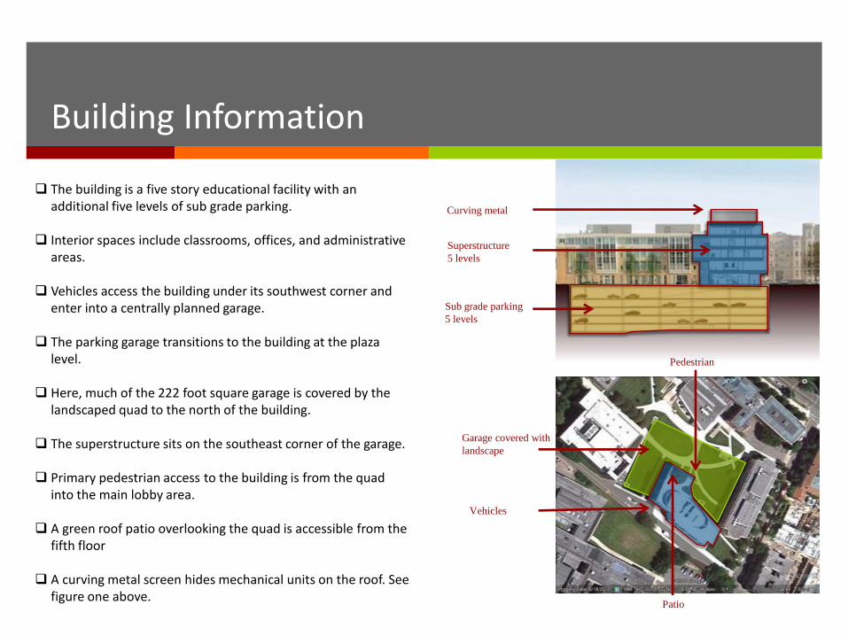
The building is a five story educational facility with an additional five levels of sub grade parking.
Interior spaces include classrooms, offices, and administrative areas.
Vehicles access the building under its southwest corner and enter into a centrally planned garage.
The parking garage transitions to the building at the plaza level.
Here, much of the 222 foot square garage is covered by the landscaped quad to the north of the building.
The superstructure sits on the southeast corner of the garage. Primary pedestrian access to the building is from the quad
into the main lobby area.
A green roof patio overlooking the quad is accessible from the fifth floor
A curving metal screen hides mechanical units on the roof. See figure one above.
Vehicles
Garage covered with
landscape
Pedestrian
Patio
Superstructure
5 levels
Sub grade parking
5 levels
Curving metal
Code Requirement & Zoning
Design Codes Building Code, Design Loads: Massachusetts State Building Code CMR 780 6th
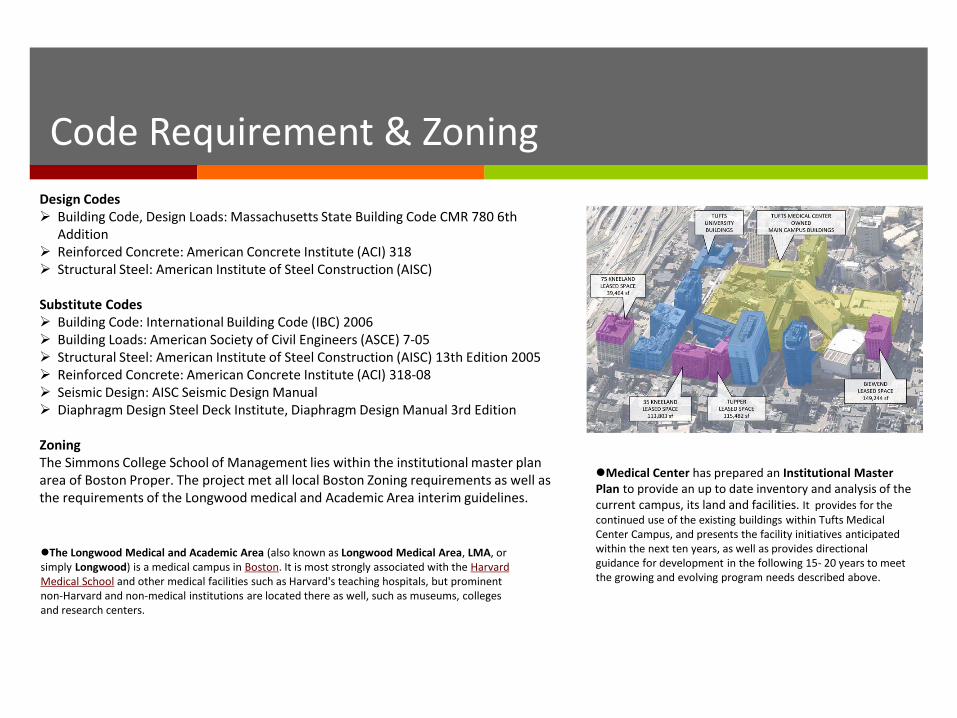
Addition Reinforced Concrete: American Concrete Institute (ACI) 318 Structural Steel: American Institute of Steel Construction (AISC) Substitute Codes Building Code: International Building Code (IBC) 2006 Building Loads: American Society of Civil Engineers (ASCE) 7‐05 Structural Steel: American Institute of Steel Construction (AISC) 13th Edition 2005 Reinforced Concrete: American Concrete Institute (ACI) 318‐08 Seismic Design: AISC Seismic Design Manual Diaphragm Design Steel Deck Institute, Diaphragm Design Manual 3rd Edition Zoning The Simmons College School of Management lies within the institutional master plan area of Boston Proper. The project met all local Boston Zoning requirements as well as the requirements of the Longwood medical and Academic Area interim guidelines.
The Longwood Medical and Academic Area (also known as Longwood Medical Area, LMA, or simply Longwood) is a medical campus in Boston. It is most strongly associated with the Harvard Medical School and other medical facilities such as Harvard's teaching hospitals, but prominent non-Harvard and non-medical institutions are located there as well, such as museums, colleges and research centers.
Medical Center has prepared an Institutional Master Plan to provide an up to date inventory and analysis of the current campus, its land and facilities. It provides for the continued use of the existing buildings within Tufts Medical Center Campus, and presents the facility initiatives anticipated within the next ten years, as well as provides directional guidance for development in the following 15- 20 years to meet the growing and evolving program needs described above.
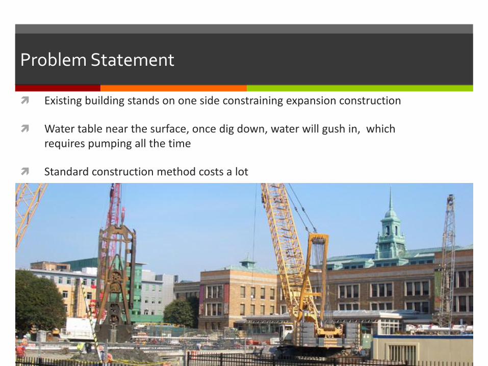
Problem Statement
Existing building stands on one side constraining expansion construction
Water table near the surface, once dig down, water will gush in, which requires pumping all the time
Standard construction method costs a lot
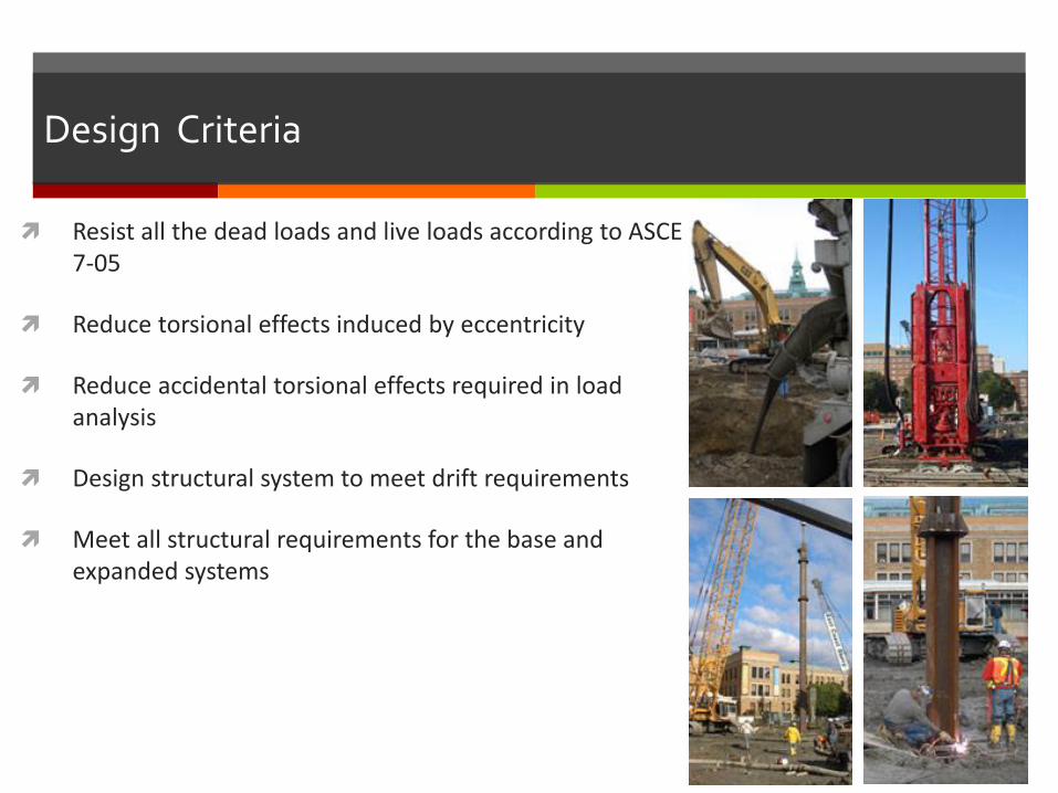
Design Criteria
Resist all the dead loads and live loads according to ASCE 7-05
Reduce torsional effects induced by eccentricity
Reduce accidental torsional effects required in load analysis
Design structural system to meet drift requirements
Meet all structural requirements for the base and expanded systems

Design Structure
Post tensioned underground parking
3 Feet slurry wall retaining system
Steel framing structure above ground
Composite action floor system
Steel brace frame lateral system
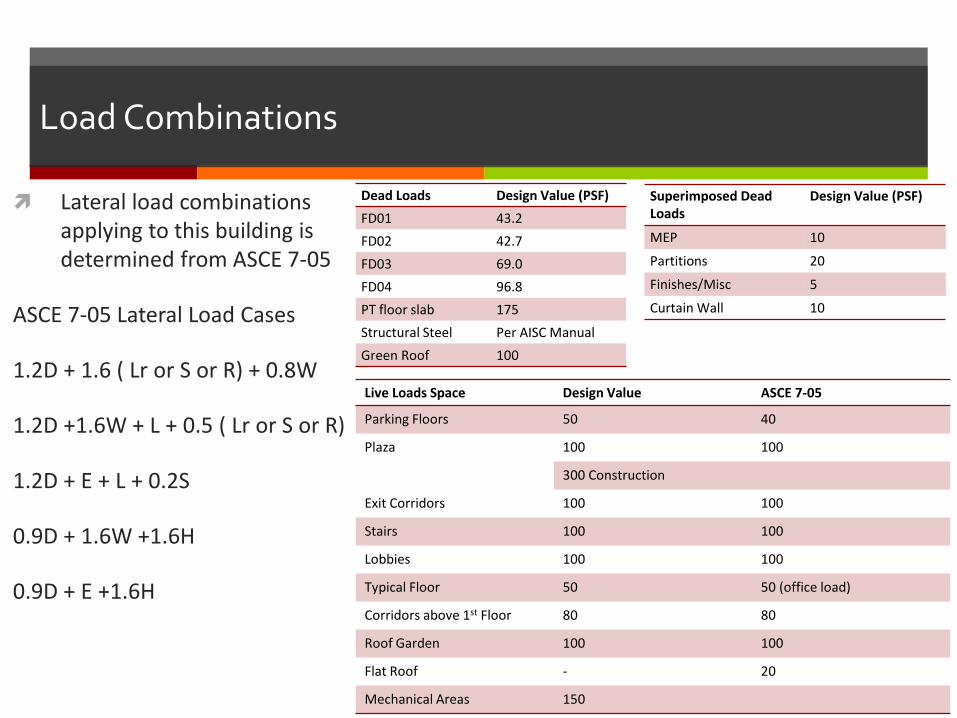
Load Combinations
Lateral load combinations applying to this building is determined from ASCE 7-05
ASCE 7-05 Lateral Load Cases
1.2D + 1.6 ( Lr or S or R) + 0.8W
1.2D +1.6W + L + 0.5 ( Lr or S or R)
1.2D + E + L + 0.2S
0.9D + 1.6W +1.6H
0.9D + E +1.6H
Dead Loads Design Value (PSF)
FD01 43.2
FD02 42.7
FD03 69.0
FD04 96.8
PT floor slab 175
Structural Steel Per AISC Manual
Green Roof 100
Live Loads Space Design Value ASCE 7-05
Parking Floors 50 40
Plaza 100 100
300 Construction
Exit Corridors 100 100
Stairs 100 100
Lobbies 100 100
Typical Floor 50 50 (office load)
Corridors above 1st Floor 80 80
Roof Garden 100 100
Flat Roof - 20
Mechanical Areas 150
Superimposed Dead Loads
Design Value (PSF)
MEP 10
Partitions 20
Finishes/Misc 5
Curtain Wall 10
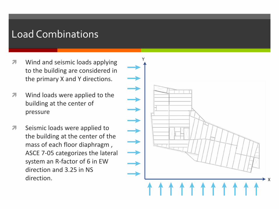
Load Combinations
Wind and seismic loads applying to the building are considered in the primary X and Y directions.
Wind loads were applied to the building at the center of pressure
Seismic loads were applied to the building at the center of the mass of each floor diaphragm , ASCE 7-05 categorizes the lateral system an R-factor of 6 in EW direction and 3.25 in NS direction.
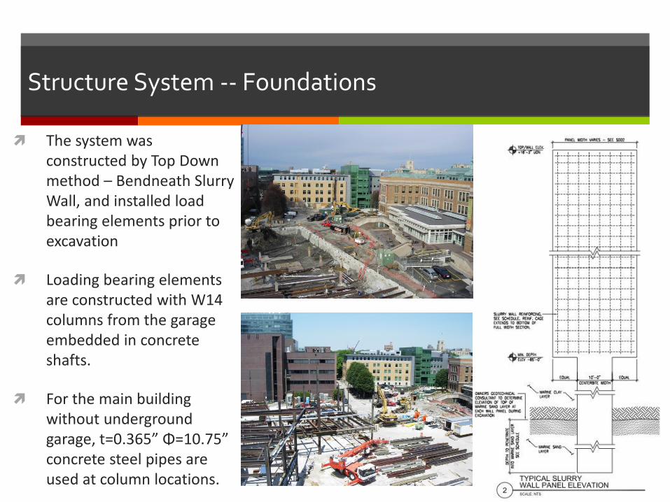
Structure System -- Foundations
The system was constructed by Top Down method – Bendneath Slurry Wall, and installed load bearing elements prior to excavation
Loading bearing elements are constructed with W14 columns from the garage embedded in concrete shafts.
For the main building without underground garage, t=0.365” Φ=10.75” concrete steel pipes are used at column locations.
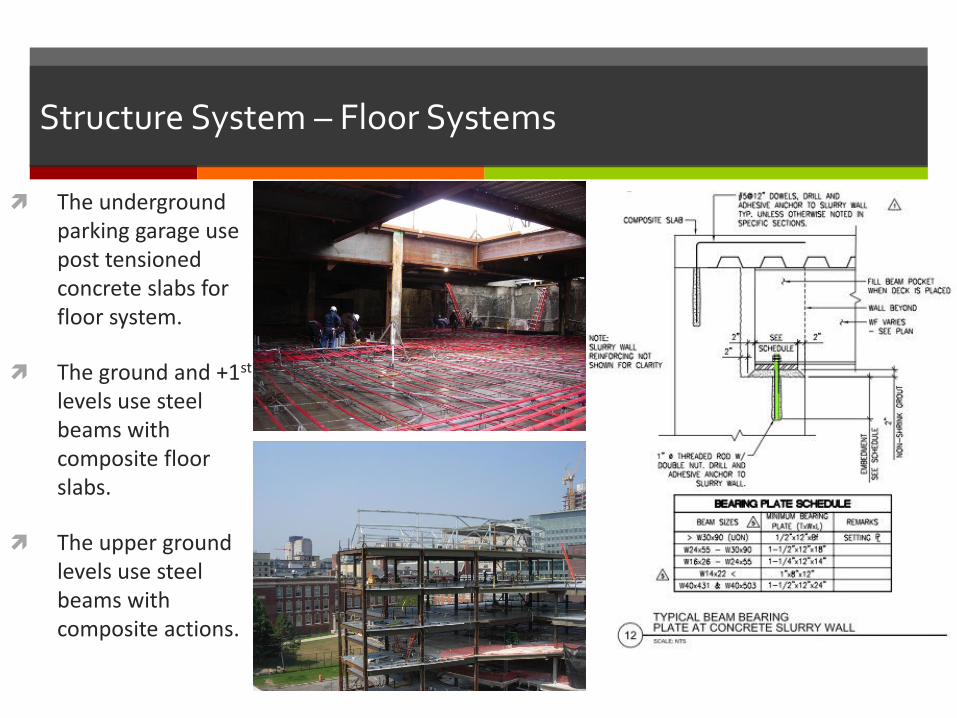
Structure System – Floor Systems
The underground parking garage use post tensioned concrete slabs for floor system.
The ground and +1st levels use steel beams with composite floor slabs.
The upper ground levels use steel beams with composite actions.
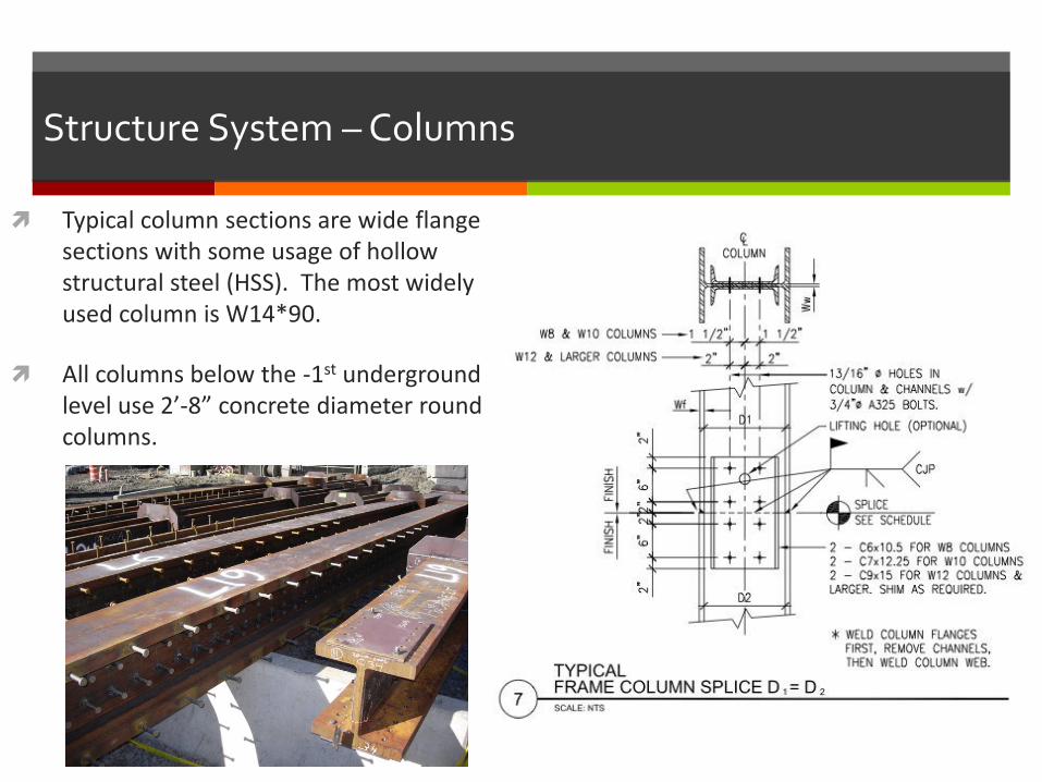
Structure System – Columns
Typical column sections are wide flange sections with some usage of hollow structural steel (HSS). The most widely used column is W14*90.
All columns below the -1st underground level use 2’-8” concrete diameter round columns.
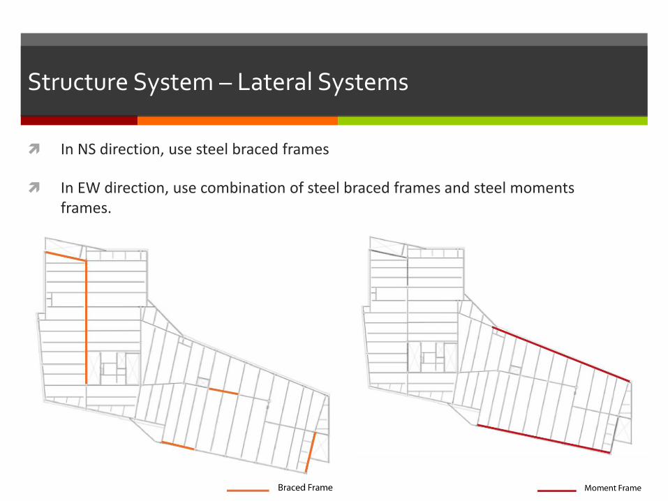
Structure System – Lateral Systems
In NS direction, use steel braced frames
In EW direction, use combination of steel braced frames and steel moments frames.
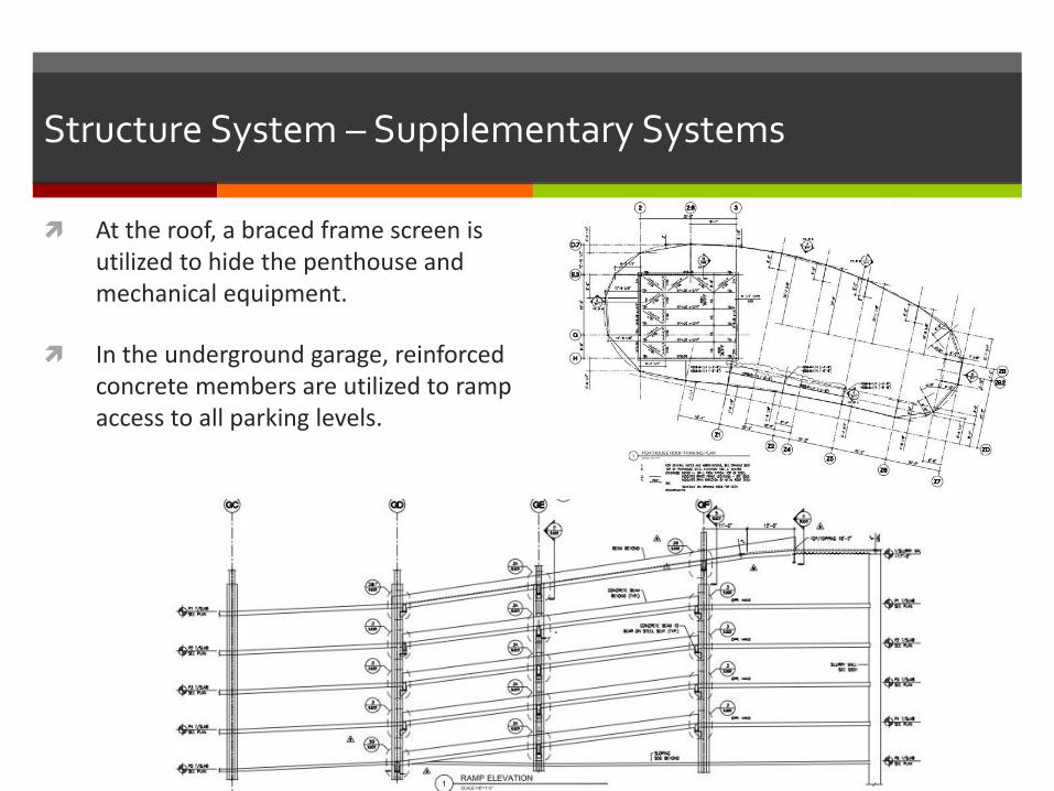
Structure System – Supplementary Systems
At the roof, a braced frame screen is utilized to hide the penthouse and mechanical equipment.
In the underground garage, reinforced concrete members are utilized to ramp access to all parking levels.
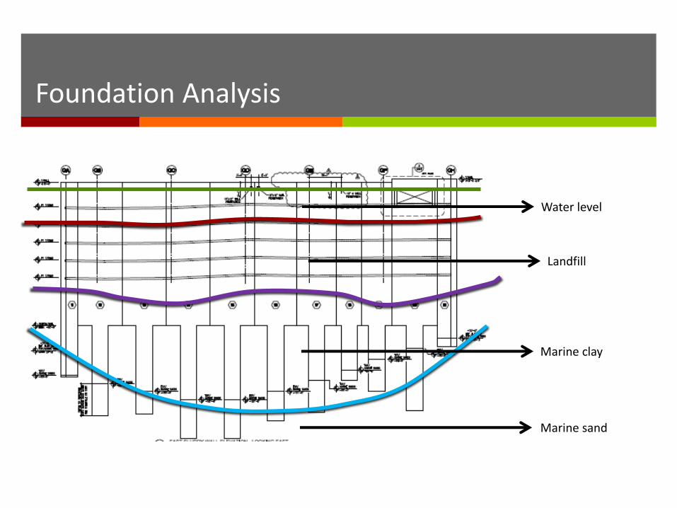
Marine sand
Marine clay
Landfill
Water level
Foundation Analysis

Structure Analysis
Mechanical Area
Existing Foundations
BENTIONITE
SLURRY WALLS
BEARING
BIGHT

Structure Analysis
Lateral Brace
Some area have large members For example: Plate Girder 58*849
Plaza Level Designed to hold 2 cranes and construction vehicle during construction
2-way post tensioned 14” concrete slabs
Steel columns with 4’ plates at slab Levels encased in flowable Field to hold in place Clipped off and encase With concrete.
5 story parking garage 600~700 spaces
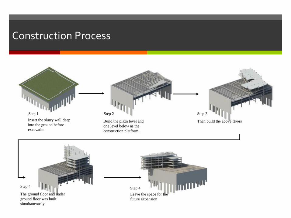
Construction Process
Step 1 Step 2
Step 4 Step 4
Insert the slurry wall deep
into the ground before
excavation
Build the plaza level and
one level below as the
construction platform.
Step 3
Then build the above floors
The ground floor and under
ground floor was built
simultaneously
Leave the space for the
future expansion
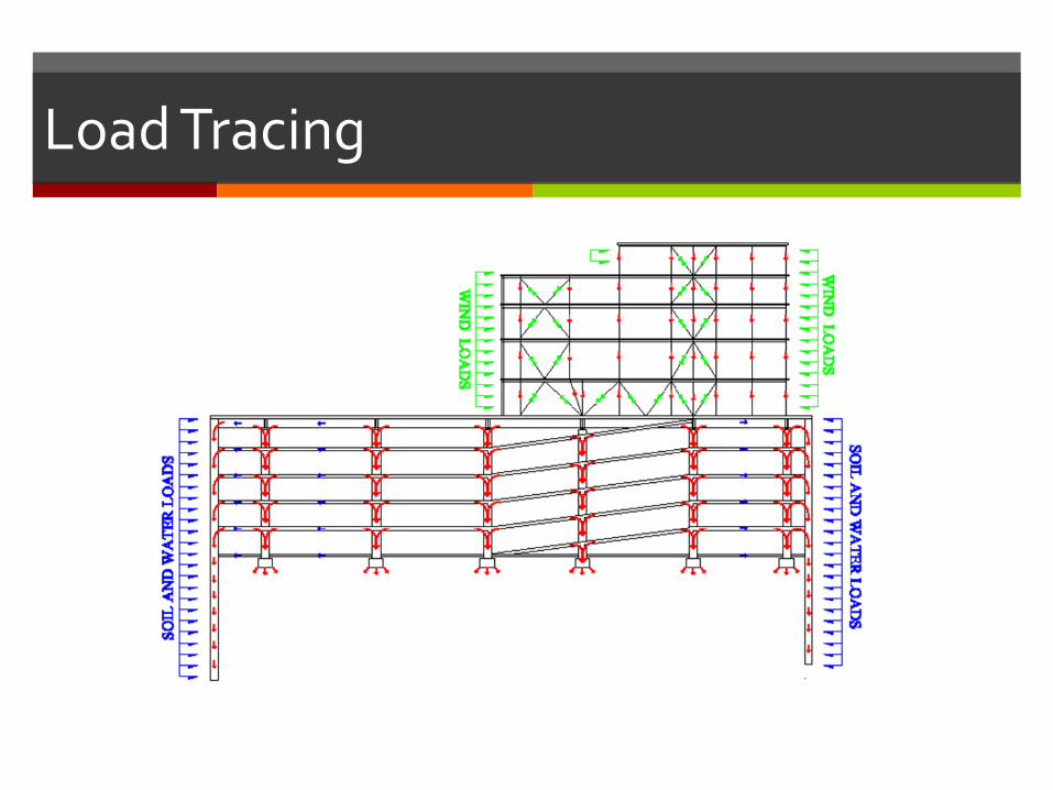
Load Tracing
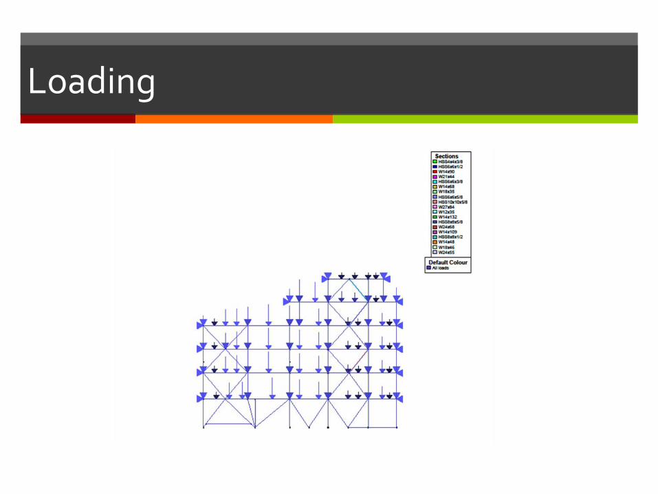
Loading
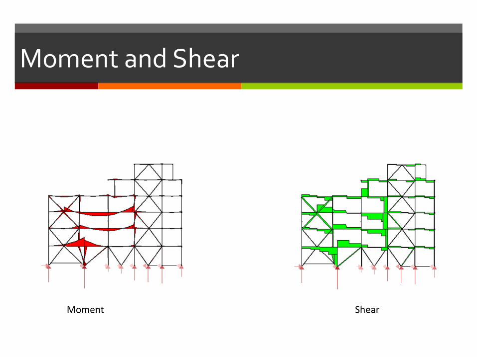
Moment and Shear
Moment Shear
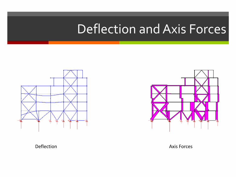
Deflection and Axis Forces
Deflection Axis Forces
Reference
East Coast Slurry
http://www.eastcoastslurry.com/simmons.html
Boston Ground Water Trust
http://www.bostongroundwater.org/let020.html
Academic Thesis
http://www.engr.psu.edu/ae/thesis/portfolios/2010/ktw5007/BuildingStatistic
s.html
Structure Drawings of Simmons School of Management and New Main
Quad, Cannon Design, 2006
Special Thanks to:
Dr. Matt Dates
John Boekelman

Questions?
THANK YOU!