structure and mechanical implications of the pectoral fin...
TRANSCRIPT

Acta Biomaterialia 51 (2017) 393–407
Contents lists available at ScienceDirect
Acta Biomaterialia
journal homepage: www.elsevier .com/locate /actabiomat
Full length article
Structure and mechanical implications of the pectoral fin skeleton in theLongnose Skate (Chondrichthyes, Batoidea)
http://dx.doi.org/10.1016/j.actbio.2017.01.0261742-7061/� 2017 Acta Materialia Inc. Published by Elsevier Ltd. All rights reserved.
⇑ Corresponding author.E-mail address: [email protected] (W. Huang).
Wei Huang a,⇑, Watcharapong Hongjamrassilp b, Jae-Young Jung a, Philip A. Hastings b, Vlado A. Lubarda a,c,Joanna McKittrick a,d
aMaterials Science and Engineering Program, University of California, San Diego, La Jolla, CA 92093, United Statesb Scripps Institution of Oceanography, University of California, San Diego, La Jolla, CA 92093, United StatescDepartment of Nanoengineering, University of California, San Diego, La Jolla, CA 92093, United StatesdDepartment of Mechanical and Aerospace Engineering, University of California, San Diego, La Jolla, CA 92093, United States
a r t i c l e i n f o a b s t r a c t
Article history:Received 29 July 2016Received in revised form 16 December 2016Accepted 5 January 2017Available online 6 January 2017
Keywords:Batoid finsUndulation swimmingHierarchical structureMineralized cartilageMechanical properties
Animal propulsion systems are believed to show high energy and mechanical efficiency in assistingmovement compared to artificial designs. As an example, batoid fishes have very light cartilaginousskeletons that facilitate their elegant swimming via enlarged wing-like pectoral fins. The aim of this workis to illustrate the hierarchical structure of the pectoral fin of a representative batoid, the Longnose Skate(Raja rhina), and explain the mechanical implications of its structural design. At the macro level, the pec-toral fins are comprised of radially oriented fin rays, formed by staggered mineralized skeletal elementsstacked end-to-end. At the micro level, the midsection of each radial element is composed of three min-eralized components, which consist of discrete segments (tesserae) that are mineralized cartilage andembedded in unmineralized cartilage. The radial elements are wrapped with aligned, unmineralized col-lagen fibers. This is the first report of the detailed structure of the ray elements, including the observationof a 3-chain mineralized tesserae. Structural analyses demonstrate that this configuration enhances stiff-ness in multiple directions. A two-dimensional numerical model based on the morphological analysisdemonstrated that the tessera structure helps distributing shear, tensile and compressive stress moreideally, which can better support both lift and thrust forces when swimming without losing flexibility.
Statement of Significance
Batoid fishes have very light cartilaginous skeletons that facilitate their elegant swimming by applyingtheir enlarged wing-like pectoral fins. Previous studies have shown structural features and mechanicalproperties of the mineralized cartilage skeleton in various batoid fishes. However, the details of the pec-toral fin structure at different length scales, as well as the relationship between the mechanical propertiesand structural design remains unknown. The present work illustrates the hierarchical structure of thepectoral fin of the Longnose Skate (a representative batoid fish) and verifies the materials configurationand structural design increases the stiffness of fin skeleton without a loss in flexibility. These results haveimplications for the design of strong but flexible materials and bio-inspired autonomous underwatervehicles (AUVs).
� 2017 Acta Materialia Inc. Published by Elsevier Ltd. All rights reserved.
1. Introduction
After �530 million years of evolution, the propulsion systems inmore than 30,000 extant fish species show remarkable variabilityand efficiency in swimming in aquatic environments [1–3]. Batoi-dea is a lineage of cartilaginous fishes, including rays, skates and
their relatives, and are distinguished by dorsoventrally flattenedbodies and enlarged pectoral fins that are contiguous with thehead. These wing-like fins are the main apparatus for batoid(ray) propulsion, termed rajiform swimming [4,5]. The movementtrajectories of their pectoral fins during swimming vary in thenumber and frequency of undulatory waves that pass along themargin of the pectoral fins [6]. Among fish propulsion systems,swimming mechanisms with pectoral fins in batoid fish specieshave motivated research interests in developing promising
394 W. Huang et al. / Acta Biomaterialia 51 (2017) 393–407
bio-inspired autonomous underwater vehicles (AUVs) [7,8]. More-over, by combining rat cardiomyocytes with artificial batoid skele-ton, Park et al. [9] realized the efficient undulatory swimming on atissue-engineered biohybrid robotic ray using optical stimulation.
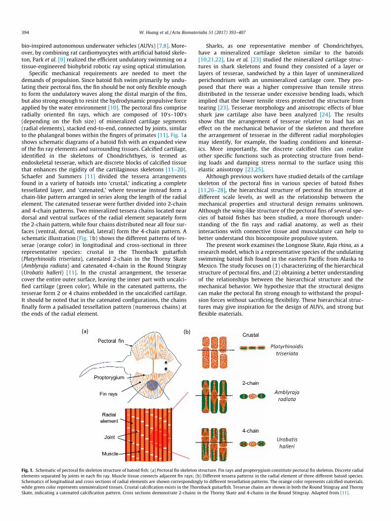
Specific mechanical requirements are needed to meet thedemands of propulsion. Since batoid fish swim primarily by undu-lating their pectoral fins, the fin should be not only flexible enoughto form the undulatory waves along the distal margin of the fins,but also strong enough to resist the hydrodynamic propulsive forceapplied by the water environment [10]. The pectoral fins compriseradially oriented fin rays, which are composed of 100s–1000s(depending on the fish size) of mineralized cartilage segments(radial elements), stacked end-to-end, connected by joints, similarto the phalangeal bones within the fingers of primates [11]. Fig. 1ashows schematic diagrams of a batoid fish with an expanded viewof the fin ray elements and surrounding tissues. Calcified cartilage,identified in the skeletons of Chondrichthyes, is termed asendoskeletal tesserae, which are discrete blocks of calcified tissuethat enhances the rigidity of the cartilaginous skeletons [11–20].Schaefer and Summers [11] divided the tessera arrangementsfound in a variety of batoids into ‘crustal,’ indicating a completetessellated layer, and ‘catenated,’ where tesserae instead form achain-like pattern arranged in series along the length of the radialelement. The catenated tesserae were further divided into 2-chainand 4-chain patterns. Two mineralized tessera chains located neardorsal and ventral surfaces of the radial element separately formthe 2-chain pattern, while four chains distributed near all four sur-faces (ventral, dorsal, medial, lateral) form the 4-chain pattern. Aschematic illustration (Fig. 1b) shows the different patterns of tes-serae (orange color) in longitudinal and cross-sectional in threerepresentative species: crustal in the Thornback guitarfish(Platyrhinoidis triseriata), catenated 2-chain in the Thorny Skate(Amblyraja radiata) and catenated 4-chain in the Round Stingray(Urobatis halleri) [11]. In the crustal arrangement, the tesseraecover the entire outer surface, leaving the inner part with uncalci-fied cartilage (green color). While in the catenated patterns, thetesserae form 2 or 4 chains embedded in the uncalcified cartilage.It should be noted that in the catenated configurations, the chainsfinally form a palisaded tessellation pattern (numerous chains) atthe ends of the radial element.
Fig. 1. Schematic of pectoral fin skeleton structure of batoid fish: (a) Pectoral fin skeletonelements separated by joints in each fin ray. Muscle tissue connects adjacent fin rays; (Schematics of longitudinal and cross sections of radial elements are shown correspondinwhile green color represents unmineralized tissues. Crustal calcification exists in the ThoSkate, indicating a catenated calcification pattern. Cross sections demonstrate 2-chains
Sharks, as one representative member of Chondrichthyes,have a mineralized cartilage skeleton similar to the batoids[10,21,22]. Liu et al. [23] studied the mineralized cartilage struc-tures in shark skeletons and found they consisted of a layer orlayers of tesserae, sandwiched by a thin layer of unmineralizedperichondrium with an unmineralized cartilage core. They pro-posed that there was a higher compressive than tensile stressdistributed in the tesserae under excessive bending loads, whichimplied that the lower tensile stress protected the structure fromtearing [23]. Tesserae morphology and anisotropic effects of blueshark jaw cartilage also have been analyzed [24]. The resultsshow that the arrangement of tesserae relative to load has aneffect on the mechanical behavior of the skeleton and thereforethe arrangement of tesserae in the different radial morphologiesmay identify, for example, the loading conditions and kinemat-ics. More importantly, the discrete calcified tiles can realizeother specific functions such as protecting structure from bend-ing loads and damping stress normal to the surface using thiselastic anisotropy [23,25].
Although previous workers have studied details of the cartilageskeleton of the pectoral fins in various species of batoid fishes[11,26–28], the hierarchical structure of pectoral fin structure atdifferent scale levels, as well as the relationship between themechanical properties and structural design remains unknown.Although the wing-like structure of the pectoral fins of several spe-cies of batoid fishes has been studied, a more thorough under-standing of the fin rays and radial anatomy, as well as theirinteractions with connective tissue and musculature can help tobetter understand this biocomposite propulsive system.
The present work examines the Longnose Skate, Raja rhina, as aresearch model, which is a representative species of the undulatingswimming batoid fish found in the eastern Pacific from Alaska toMexico. The study focuses on (1) characterizing of the hierarchicalstructure of pectoral fins, and (2) obtaining a better understandingof the relationships between the hierarchical structure and themechanical behavior. We hypothesize that the structural designscan make the pectoral fin strong enough to withstand the propul-sion forces without sacrificing flexibility. These hierarchical struc-tures may give inspiration for the design of AUVs, and strong butflexible materials.
structure. Fin rays and propterygium constitute pectoral fin skeleton. Discrete radialb) Different tessera patterns in the radial element of three different batoid species.gly to different tessellation patterns. The orange color represents calcified materials,rnback guitarfish. Tesserae chains are shown in both the Round Stingray and Thornyin the Thorny Skate and 4-chains in the Round Stingray. Adapted from [11].

W. Huang et al. / Acta Biomaterialia 51 (2017) 393–407 395
2. Materials and methods
2.1. Sample collection
Three Longnose Skates were acquired from a �340 m depthnear the San Diego coastline during a Scripps Institution ofOceanography research cruise on April, 20, 2015. The specimenswere collected under IACUC protocol S02118. The fish were imme-diately stored at �20 �C before further analysis.
2.2. X-ray images
Fresh specimens were radiographed using a Faxitron ModelMX-20 cabinet radiography system (Tucson, AZ, USA) under24 kV for 8 s with image plate. The image plate, which was exposedwith X-ray radiation, was scanned in a ScanX-12 reader (Melville,NY, USA) to generate the X-ray image.
2.3. Micro-computed tomography (l-CT)
Samples from the midsection of the pectoral fin were preparedby immersion in a saline solution to keep the whole structurehydrated. The pectoral fin skeleton was analyzed using a Skyscan1076 l-CT scanner (Bruker, Kontich, Belgium) with a 0.5 mm alu-minum filter. The isotropic voxel size was 9 lm, the electric poten-tial was 70 peak kV (kVp), and the current was 200 lA. Afterscanning, a post-scan beam hardening correction algorithm wasapplied during image reconstruction. Skyscan’s Dataviewer andCTVox software (Bruker, Kontich, Belgium) was used to acquireimages and Amira software (FEI Visualization Sciences Group,Burlington, MA) was used for 3D rendered models.
2.4. Histology
Radial elements were cut from pectoral fin samples of the Long-nose Skate, and were fixed overnight in 4% formaldehyde solution.The samples then were decalcified in RDO rapid decalcifier (ApexEngineering Products Corporation, Aurora, IL) for 2 h. Once decalci-fied, the samples were transferred into a graded series of ethanolfrom 50%, 70%, 95%, to absolute ethanol for dehydration. The sam-ples then were placed in xylene, which was changed every 20 minfor three times before embedding in Paraplast (McCormick Scien-tific, St. Louis, MO). Finally, the samples were cut by a microtomeinto 5–7 lm sections and mounted on glass slide. Hematoxylin &Eosin (H&E) was used for staining. Optical microscopy images ofstained slides were taken using Zeiss Axio imager equipped withCCD camera (Zeiss MicroImaging Inc., Thornwood, NY, USA) undertransmitted light.
2.5. Scanning electron microscopy (SEM)
The fins were sectioned to extract several fin ray radial ele-ments from the midsection of the fin. The radial elements wereimmersed in a 2.5 vol% glutaraldehyde solution for two hours tofix the structure. A graded series of ethanol solutions (20%, 40%,60%, 80%, 95%, and 100% vol% ethanol) were applied to furtherdehydrate the samples. Some of the samples were then freeze-fractured after immersion in liquid nitrogen in both cross and lon-gitudinal directions. Finally, a critical point dryer (Autosamdri-851,Tousimis, Rockville, MD, USA) was used to further remove theexcess ethanol. The other samples were embedded in LR whiteresin (Electron Microscopy Sciences, PA, USA) and then polishedto a flat surface. All the samples were sputter coated with iridium(Quorum Technologies Ltd., West Sussex, UK) before carrying outSEM imaging. Imaging was carried out with an ultra-high resolu-
tion microscope (FEI XL30, Hillsboro, OR, USA). During imaging,energy dispersive X-ray spectroscopy (EDS) and backscatteringscanning electron microscopy (BSEM) were performed to acquireelemental compositions and mineral density.
2.6. Tensile tests
Tension testing was performed on nine fresh fin radial ele-ments. Both skin and flesh surrounding the radial element wasremoved carefully by surgical knife. The fresh samples were storedin the refrigerator and kept in DI water �2 h before testing. Aninstrumented load frame (Instron 3367, Instron Corporation, Nor-wood, MA, USA) with a load cell of 500 N was used to performthe tensile tests at a strain rate of 10�3 s�1. Small pieces of sandpaper were applied to glue the non-active areas of the samplesto prevent sample sliding during tension and diminish local stressconcentration. The gauge lengths of the samples were �5 mm,which was the length of a single radial element. The cross sectionof the samples was assumed circular shape with diameters�0.5 mm. The fractured surfaces of all the samples were imagedunder SEM using the above procedure.
3. Results and discussion
3.1. Macrostructural characterization
Fig. 2a shows a photograph of a Longnose Skate, having a totallength of �25 cm and disc width of �15 cm. The whole skeletalstructure is shown in the X-ray image in Fig. 2b showing the con-nection of the pectoral fins to the propterygium support elements.As shown in a higher magnification X-ray image (Fig. 2c), the pec-toral fin is composed of �70 mineralized fin rays, which consist ofseries of radial elements connected end-to-end separated by a lar-ger diameter joint. A staggered periodic pattern of the joints isobserved, analogous to those reported for other rays [11]. Detailedstructures of radial elements in Fig. 2d show several mineralizedtesserae chains in each radial element and a higher mineralizedarea in the joints, and the location for the SEM and EDS studies.
3.2. Microstructure and composition
Micro-CT images of a representative midsection of the pectoralfin as well as single radial element are shown in Fig. 3. The averagelength of the radial elements is �5.5 mm and the diameters varyfrom �0.48 mm at the midsection to �0.95 mm at the distal end.From Fig. 3a, it can be observed that the fin rays bifurcate intotwo branches �2/3 of the length from the proximal region. Fromthe dorsal view at a higher magnification (Fig. 3b), the proximal-distal position of the joints is not the same for each ray; the posi-tion mismatch of the nearest two joints in adjacent fin rays is�1.2 mm. This joint position mismatch is thought to facilitate avariety of kinematic motions [8]. A cross section of a fin element(Fig. 3c) shows the dorsal and ventral components, but the dorsaltessera chain has two separate components, resulting in a 3-chain configuration. To the best of our knowledge, this is the firstreport of a 3-chain tesserae configuration. Each tessera has anaverage diameter �100 lm. The mineral density increases fromthe outer surface to the inner core, indicating that softer tissuessurround the higher mineralized core. This can be related to thebackscatter scanning electron microscopy images of Urobatis hal-leri, which showed mineralized tesserae wrapped by unmineral-ized perichondrium [20]. As shown in Fig. 3d, the pectoral finsare bent at �60�. This is accomplished by employing �15 radialelements; only a �4� orientation change between adjacent radialelements is necessary to achieve the large 60� angle.

Fig. 2. The Longnose Skate skeleton and pectoral-fin structure: (a) Photograph of a fish collected along the San Diego coastline; (b) X-ray image of the whole skeleton; (c)Conjunction between the fin rays and the propterygium support element (orange box in (b)). Propterygium is indicated in the figure as the starting of fin rays. The fin rays arecomposed of radial elements separated by joints. The yellow circle shows the radial element samples used for scanning electron microscopy and electron dispersive X-rayspectroscopy analysis (Figs. 5, 6 and 7); (d) High magnification X-ray image of detailed radial elements and joints in the fin rays.
Fig. 3. Micro-computed tomography images of fin rays and radial elements: (a) Dorsal section of the left pectoral fin skeleton; (b) Dorsal view of radial elements and thejoints between elements, single radial element is shown at a higher magnification; (c) Cross-section of radial element, showing three mineralized components in eachelement. The green color has a lower mineral density, the red color has a higher mineral density; (d) The pectoral fin bent �60�, showing a gradually bending of each radialelement. White scale bar (a) and (d): 5 mm, black scale bar (b): 1 mm.
396 W. Huang et al. / Acta Biomaterialia 51 (2017) 393–407
From analysis of the l-CT images (see Fig. 4 caption), the totalarea and percent of the mineralized tesserae in the cross sectionof five adjacent fin rays are plotted as a function of the distance
from the proximal end of the fin rays (Fig. 4a). The purple stripsin each fin ray indicate the 3-chain sections. The white areasbetween the purple strips are the highly mineralized ends of each
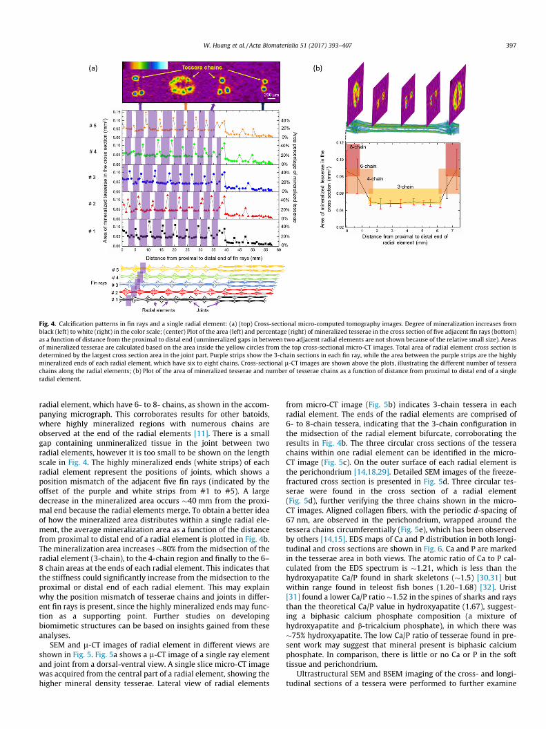
Fig. 4. Calcification patterns in fin rays and a single radial element: (a) (top) Cross-sectional micro-computed tomography images. Degree of mineralization increases fromblack (left) to white (right) in the color scale; (center) Plot of the area (left) and percentage (right) of mineralized tesserae in the cross section of five adjacent fin rays (bottom)as a function of distance from the proximal to distal end (unmineralized gaps in between two adjacent radial elements are not shown because of the relative small size). Areasof mineralized tesserae are calculated based on the area inside the yellow circles from the top cross-sectional micro-CT images. Total area of radial element cross section isdetermined by the largest cross section area in the joint part. Purple strips show the 3-chain sections in each fin ray, while the area between the purple strips are the highlymineralized ends of each radial element, which have six to eight chains. Cross-sectional l-CT images are shown above the plots, illustrating the different number of tesserachains along the radial elements; (b) Plot of the area of mineralized tesserae and number of tesserae chains as a function of distance from proximal to distal end of a singleradial element.
W. Huang et al. / Acta Biomaterialia 51 (2017) 393–407 397
radial element, which have 6- to 8- chains, as shown in the accom-panying micrograph. This corroborates results for other batoids,where highly mineralized regions with numerous chains areobserved at the end of the radial elements [11]. There is a smallgap containing unmineralized tissue in the joint between tworadial elements, however it is too small to be shown on the lengthscale in Fig. 4. The highly mineralized ends (white strips) of eachradial element represent the positions of joints, which shows aposition mismatch of the adjacent five fin rays (indicated by theoffset of the purple and white strips from #1 to #5). A largedecrease in the mineralized area occurs �40 mm from the proxi-mal end because the radial elements merge. To obtain a better ideaof how the mineralized area distributes within a single radial ele-ment, the average mineralization area as a function of the distancefrom proximal to distal end of a radial element is plotted in Fig. 4b.The mineralization area increases �80% from the midsection of theradial element (3-chain), to the 4-chain region and finally to the 6–8 chain areas at the ends of each radial element. This indicates thatthe stiffness could significantly increase from the midsection to theproximal or distal end of each radial element. This may explainwhy the position mismatch of tesserae chains and joints in differ-ent fin rays is present, since the highly mineralized ends may func-tion as a supporting point. Further studies on developingbiomimetic structures can be based on insights gained from theseanalyses.
SEM and l-CT images of radial element in different views areshown in Fig. 5. Fig. 5a shows a l-CT image of a single ray elementand joint from a dorsal-ventral view. A single slice micro-CT imagewas acquired from the central part of a radial element, showing thehigher mineral density tesserae. Lateral view of radial elements
from micro-CT image (Fig. 5b) indicates 3-chain tessera in eachradial element. The ends of the radial elements are comprised of6- to 8-chain tessera, indicating that the 3-chain configuration inthe midsection of the radial element bifurcate, corroborating theresults in Fig. 4b. The three circular cross sections of the tesserachains within one radial element can be identified in the micro-CT image (Fig. 5c). On the outer surface of each radial element isthe perichondrium [14,18,29]. Detailed SEM images of the freeze-fractured cross section is presented in Fig. 5d. Three circular tes-serae were found in the cross section of a radial element(Fig. 5d), further verifying the three chains shown in the micro-CT images. Aligned collagen fibers, with the periodic d-spacing of67 nm, are observed in the perichondrium, wrapped around thetessera chains circumferentially (Fig. 5e), which has been observedby others [14,15]. EDS maps of Ca and P distribution in both longi-tudinal and cross sections are shown in Fig. 6. Ca and P are markedin the tesserae area in both views. The atomic ratio of Ca to P cal-culated from the EDS spectrum is �1.21, which is less than thehydroxyapatite Ca/P found in shark skeletons (�1.5) [30,31] butwithin range found in teleost fish bones (1.20–1.68) [32]. Urist[31] found a lower Ca/P ratio �1.52 in the spines of sharks and raysthan the theoretical Ca/P value in hydroxyapatite (1.67), suggest-ing a biphasic calcium phosphate composition (a mixture ofhydroxyapatite and b-tricalcium phosphate), in which there was�75% hydroxyapatite. The low Ca/P ratio of tesserae found in pre-sent work may suggest that mineral present is biphasic calciumphosphate. In comparison, there is little or no Ca or P in the softtissue and perichondrium.
Ultrastructural SEM and BSEM imaging of the cross- and longi-tudinal sections of a tessera were performed to further examine

Fig. 5. Scanning electron microscopy and micro-computed tomography images of radial elements at different views. Images taken from the center of a radial element fromthe midsection of the pectoral fin: (a) Micro-computed tomography image of dorsal-ventral view of a radial element and the joint. Micro-computed tomography slice shows aseries of discrete mineralized tesserae along the radial elements. The red color means higher mineral density corresponding to highly mineralized tesserae. The cartilage is ingreen, showing a lower mineral density; (b) Lateral view of radial elements and joints. Three tesserae chains in each radial element are shown; (c) Micro-computedtomography image of cross section of a radial element, showing three circular Mineralized tesserae and the surrounding unmineralized perichondrium soft tissue; (d)Microscopy image of cross section of a radial element. Three circular tesserae are observed; (e) Aligned collagen fibers are found in the outer layer of perichondrium that wraparound the tesserae.
398 W. Huang et al. / Acta Biomaterialia 51 (2017) 393–407
the mineral distribution. The white circular area in a BSEM image(Fig. 7a) indicates that the tessera have a larger degree of mineral-ization. A high magnification image of a chondrocyte lacuna from atessera shows fibrous network structure (Fig. 7b). No crystals areobserved in the unmineralized tissue that surrounds the tessera(Fig. 7c). In contrast, a large number of mineralized nanoparticlesare found in the tessera (Fig. 7d). Fig. 7e shows a BSEM image ofthe longitudinal section, indicating the discrete nature of highlymineralized tesserae chains and unmineralized tissue betweenintertesseral gaps. No crystals are found in the intertesseral gaps,but a fiber-like structure is observed (Fig. 7f), corroborating theresults of Seidel et al. [20] who found collagen fibers bundles inthe intertesseral gaps in the Round Stingray. Further studies areneeded to identify the composition of the unmineralized tissuesin these gaps in the Longnose Skate. These results further verifythat the highest mineral density is within the tesserae and no min-erals are found in the soft tissue surrounding and between them.
As a comparison to the SEM images, the longitudinal and crosssection of the radial elements were stained with hematoxylin andeosin and observed with the optical microscope (Fig. 8). The dis-crete nature of tesserae is visible when Fig. 8a and b are compared;the former being a longitudinal optical microscopy section whilethe latter is a BSEM image. Muscle fibers are indicated in Fig. 8csurrounding the radial elements. The dark pink A-band and lightpink I-band are comparable with the results in Fig. 5f, furtherdemonstrating the existence of muscle fibers between the radialelements. A large number of chondrocytes occupy the jointsbetween radial elements compared to the surrounding tissue
(Fig. 8d). Three tesserae are observed in both the dorsal and ventralarea in the cross section of the radial element near the joints(Fig. 8e). These six tesserae will eventually evolve into a 3-chaintessera (two in the dorsal and one in ventral) in the central partof the radial element, according to the structure observed inFig. 3c and Fig. 4. Although tesseral spokes were observed in Uro-batis halleri [20], we do not clearly observe them in the presentimages.
A schematic diagram of the hierarchical structure of the fin rays,compiled from the above structural results, is shown in Fig. 9. Atthe macro level (�1 mm), the fin rays are composed of �15–20end-to-end cartilaginous radial elements, which are separated byjoints, forming a staggered pattern across the fin. At a micro level(�100 lm), the radial elements are composed of three parallel,chains of tesserae, which bifurcate at the radial ends to form 6-to 8-chains. These chains are formed by a series of discrete, cylin-drical mineralized cartilaginous tissue. The tessera chains areembedded in an unmineralized cartilage matrix. In the longitudinaldirection, the tesserae are separated by a gap of �5 lm, which isfilled with unmineralized tissue. Between adjacent fin rays aremuscle fibers. At the nano level (�100 nm), collagen fibers arefound in the perichondrium forming the outer layer of the radialelements.
3.3. Force analysis of undulation swimming
The fin elements can be considered as cantilever beams, and thestiffness of these beams directly affect the swimming efficiency

Fig. 6. Scanning electron microscopy images and electron dispersive X-ray spectroscopy (EDS) element maps and spectrum of the cross- and longitudinal sections of a radialelement: Top: Cross-section of a tessera; Middle: Longitudinal section of a tessera series. Both show higher distribution of Ca and P in the tessera area, indicating a highermineral density in the tesserae part; Bottom: EDS spectrum and elemental atomic concentration of a tessera.
W. Huang et al. / Acta Biomaterialia 51 (2017) 393–407 399
[11]. From beam theory, the stiffness is determined by Young’smodulus (E) and second moment of inertia (I). Since the batoidfishes need to keep their body as light as possible to keep buoyantbecause of the absence of a swim bladder, their cartilage skeletonhelps to decrease their body weight [4,33]. However, this decreasein the Young’s modulus leads to lower bending stiffness, whichlimits the efficient transmission of large forces during swimming.[34,35]. To solve this contradiction, a hierarchy was evolved toincrease the stiffness of the whole fin skeleton using very fewmaterials.
The bending force in the pectoral fin varies with time and posi-tion. Fig. 10 shows the force loading in the fin rays during undula-tory swimming. The force can be divided into lift (y-axis) andthrust (x-axis) force, and the final combined forces vary in direc-tions depending on the time and position during swimming [36].As a result, the radial elements need to survive bending momentsin all directions. From the l-CT, SEM and histology images, it wasdemonstrated that the radial elements are composed of three min-eralized tessera chains, two dorsal and one ventral, which ishypothesized to solve the problem of having forces applied in dif-ferent directions. If a uniform load, q, is applied on a beam, thedeflection d is:
d ¼ qL4=8EI
where L is the average length. This equation can be applied to anal-ysis of bending of the radial elements. A decrease in deflection canbe realized by minimizing the length of radial elements or increas-ing E and/or I. Fig. A1 (Appendix I) is a schematic of the crustal, 2-chain, 3-chain and 4-chain calcification patterns. Following the pre-vious analysis of Schaeffer and Summers [11], let A be equal to theoverall cross-sectional area of a radial element and Actotal be equal tothe total cross-sectional area of the mineralized tesserae, then the
second moment of inertia in the lift direction (x is the neutral axis)and thrust direction (y is the neutral axis) are (see Appendix I forfurther details):
Ix;crustal ¼ Iy;crustal ¼ð2A� Actotal ÞActotal
4p
ðActotal 6 AÞ
Ix;2�chain ¼ ð8Aþ 5Actotal � 8ffiffiffiffiffiffiffiffiffiffiffiffiffiffiffiffi2AActotal
p Þ8p
Actotal ; Iy;2�chain ¼A2ctotal
8p;
ðActotal 6 0:5AÞ
Ix;3�chain ¼ Iy;3�chain ¼ A2ctotal
12p þ Actotal
2
ffiffiffiffiAp
r�
ffiffiffiffiffiffiffiffiffiffiActotal
3p
r !2
¼ ð3Actotal þ 6A� 4ffiffiffiffiffiffiffiffiffiffiffiffiffiffiffiffi3AActotal
p Þ12p
Actotal
ðActotal 6 0:66AÞ
Ix;4�chain ¼ Iy;4�chain ¼ ð8Aþ 3Actotal � 8ffiffiffiffiffiffiffiffiffiffiffiffiffiAActotal
p Þ16p
Actotal
ðActotal 6 0:68AÞBy calculating the I for the different formations, it is found that
there is a limitation to Ac for each pattern. For the crustal pattern,the maximum calcification area, Actotal , can be equal to A. While inthe other patterns, Ac is limited by geometry. The largest Ix in each
tessellated pattern can be calculated: Ix;crustal ¼ 0:25A2=p,
Ix;2�chain ¼ 0:16A2=p, Iy;3�chain ¼ 0:13A2
=p, Ix;4�chain ¼ 0:15A2=p. By

Fig. 7. Ultrastructural scanning electron microscopy and backscattering scanning electron microscopy images of the cross- and longitudinal sections of a single radialelement: (a) Backscattering scanning electron microscopy image of the cross-section showing the tesserae and unmineralized cartilage surrounding the tesserae; (b)Structure inside a chondrocyte lacuna at a higher magnification; (c) Ultrastructure of unmineralized cartilage surrounding the tesserae; (d) Calcium phosphate crystals in themineralized tessera; (e) Backscattering scanning electron microscopy image of longitudinal section showing tesserae (white) and the intertesseral gap between adjacenttessera; (f) Unmineralized tissue in the intertesseral gap.
400 W. Huang et al. / Acta Biomaterialia 51 (2017) 393–407
keeping the calcification area Actotal ¼ 0:5A as a constant, the Ix val-
ues for different patterns can be compared: Ix;crustal ¼ 0:19A2=p,
Ix;2�chain ¼ 0:16A2=p, Ix;3�chain ¼ 0:11A2
=p, Ix;4�chain ¼ 0:12A2=p. Ix in
crustal pattern is the largest, while it is smaller for the 2-, 3- and4-chain configurations. From the perspective of obtaining the high-est stiffness, the crustal configuration is the best. The bending forcedoes not just come only from dorsoventral (y-axis) motion,thus the x-axis is not always the neutral axis. The maximum Iyin the perpendicular direction with y as the neutral axis,
Iy;crustal ¼ 0:19=p; Iy;2�chain ¼ 0:03A2=p,Iy;3�chain ¼ 0:11A2
=p, Iy;4�chain¼0:12A2
=p . For the 2-chain structure, once the bending forcechanges from thrust to lift, the neutral axis changes from the x-to the y-axis, it was previously found that I decreases �80% [11],which is comparable with the present results. This dramaticdecrease of stiffness along the y-axis makes it harder to supportthe thrust force in this direction. Although the crustal calcificationpattern provides the highest stiffness in all force directions, the 3-and 4-chain patterns allow for angle-independent stiffness withbetter flexibility. In the present work, l-CT and SEM images showthe pectoral fins of the Longnose Skate have a 3-chain structure,indicating its pectoral fins can withstand force from various angles.
3.4. Mechanical implication of the tesserae structure
Tesserae structures have long been considered as a design toincrease the resistance to fatigue damage as well as extremebending [23]. A schematic of the cross section of a 2-chain radialelement is employed to explain the stress distribution using acantilever beam model under a uniform load q (Fig. 11a). In theschematic diagram, sandwich beam theory is applied [37]. Inthe core is the unmineralized cartilage with a low Young’s mod-ulus. Surrounding this are the highly mineralized tessera chainswith higher Young’s modulus. According to the Euler-Bernoullitheory, the axial strain (exxðx; zÞ) and stress (rxxðx; zÞ) can be cal-culated as:
exxðx; zÞ ¼ �zd2w
dx2
rxxðx; zÞ ¼ �zEðzÞd2w
dx2
where w represents the deflection and E(z) is the Young’s modulus.The bending moment and shear force is then given by:

Fig. 8. Optical microscopy images of hematoxylin and eosin stained fin radial element sections. (a) Longitudinal cross section where chondrocytes (CH, white areas), calcifiedcartilage tesserae (T, dark purple) and unmineralized cartilage (UC, light purple) are indicated. Unmineralized tissue is shown in the gap between the tesserae (IG,intertesseral gap). (b) Backscattering scanning electron microscopy image of a longitudinal section as a comparison, showing the discrete mineralized tesserae (white) andintertesseral gaps. (c) Muscle fibers (M) on the outer layer of the radial element. Dark pink color of A band and light pink of I band are shown. The perichondrium (PC) isshown sandwiched between the cartilage and muscle fibers. (d) Chondrocytes in the joint between two adjacent radial elements. (e) Cross section of a single radial elementnear the joint. Dorsal and ventral tesserae are indicated in dark purple color.
W. Huang et al. / Acta Biomaterialia 51 (2017) 393–407 401
Fig. 9. Hierarchical structure of the pectoral fin in the Longnose Skate (Raja rhina): Level I: amino acids, which are the basic components of collagen; level II: tropocollagen;level III: collagen network in the perichondrium; level IV: radial element, which is composed of a series of three mineralized tesserae (yellow), which are sounding by softperichondrium (green). Between the tesserae is unmineralized cartilage (red); level IV*: muscle fibers are found between radial elements; level V: pectoral fin consists ofseveral finger like fin rays, and each fin ray has end-to-end connected radial elements.

Fig. 10. Force analysis in undulation swimming: schematic of pectoral fin inundulation swimming. X is the swimming direction, pectoral fin forms a sine wave-like shape during undulation, the force on a single fin ray can be divided into liftforce and thrust force, and the final force is perpendicular to the fin surface with ismarked as P. P can be in various directions as the time and position of fin rayschange.
Fig. 11. Schematic diagram of sandwich model of a 2-chain structure duringbending: (a) Longitudinal section of a radial element before applying uniform forceq and (b) bending results showing how the discrete cylindrical tesserae deformunder tension and compression. Orange areas are the discrete tesserae and thegreen line is the soft tissue (collagen) that wraps the tesserae. The white regions arethe soft unmineralized cartilage. The purple dotted line is the neutral axis.f = tesserae thickness, 2 h = thickness of unmineralized cartilage. Q = shear force andM = bending moment.
402 W. Huang et al. / Acta Biomaterialia 51 (2017) 393–407
MxðxÞ ¼Z Z z
rxxdzdy ¼ �Dd2w
dx2
D ¼Z Z
z2EðzÞdzdy
Fig. 12. Tensile stress-strain curves for a single radial element under quasi-staticuniaxial loading.
Qx ¼dMx
dx
where D is the flexural stiffness of the beam, Mx is the bendingmoment, Qx is the shearing force. For a sandwich structure of unitwidth (y-direction) with a 2h (�1 mm) thick core (unmineralizedcartilage core), and two face materials (mineralized tesserae) withthickness f (�100 lm) with the Young’s modulus of unmineralized
cartilage core and tesserae face materials Ec and Ef , respectively. Theaxial and shear stresses in the beam are (assuming that Ef � Ec andf � 2h):
r fxx � �Mx
2fh; rc
xx � 0
s fxz � 0; scxz �
Qx
2h
where r fxx and rc
xx are the axial stresses on the face and core mate-
rial respectively and s fxz and scxz are the shear stresses on the tes-
serae face and unmineralized cartilage core, respectively. It can beconcluded that the axial forces are carried by the tessera series,while the shear stresses are taken by the unmineralized cartilagecore [38]. As a result, under bending, the main stresses on the min-eralized tessera series are subjected to uniaxial tensile or compres-sive stress. The discrete nature of the tessera structure withunmineralized cartilage between each tessera makes it possible tosustain large tensile strains, as shown in Fig. 11b.
Fig. 12 shows single fin element tensile test stress-strain curve,which shows similar tensile behavior of other biopolymers such ascollagen, presenting a J-shaped curve. This is reasonable because ofthe mineralized tesserae are discrete and the load is mainly carriedby the organic material present in the intertesseral joint. This issupported by the large maximum strain of �15–20%, which isnot achievable in a ceramic phase. The maximum strain here iscomparable with the pure cartilage in hagfish [39]. The ultimatestrength is �5 MPa, the ultimate strain is �0.20 and the Young’smodulus is �20 MPa. This is comparable to the compressivestrength, ultimate strain and stiffness of vertebrate in a TorpedoRay (4.5 MPa, 0.22 and 25.5 MPa, respectively), a batoid fish [40],as shown in Table 1. Russo et al. [8] examined the tensile responseof cartilage extracted from Cownose and Atlantic Rays. The stress-strain curves were not reported, only the fracture strain of �0.15,which corroborated the present result. The mineralized cartilagevertebrae in Sand Tiger Sharks have compressive strength, ultimatestrain and stiffness of 16 MPa, 0.14 and 167 MPa, respectively [41],similar to values found in vertebrae and hyomandibular cartilagein Smooth-hound sharks [42,43]. In comparison, the elastic modu-lus of lamprey annular cartilage (unmineralized) ranged from 0.71to 4.85 MPa, while cartilage from bovine ears (unmineralized) wasaround 1.94 MPa [44]. The reason of this ten fold increase of theYoung’s modulus reported here in mineralized cartilage overunmineralized cartilage can be attributed to the presence of amineral phase.
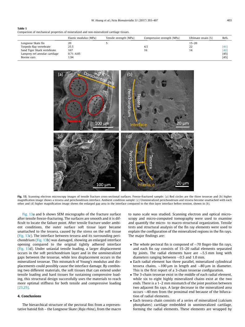
Table 1Comparison of mechanical properties of mineralized and non-mineralized cartilage tissues.
Elastic modulus (MPa) Tensile strength (MPa) Compressive strength (MPa) Ultimate strain (%) Refs.
Longnose Skate fin 20 5 15–20Torpedo Ray vertebrate 25.5 4.5 22 [41]Sand Tiger Shark vertebrate 167 16 14 [42]Lamprey eel annular cartilage 0.71–4.85 [45]Bovine ears 1.94 [45]
Fig. 13. Scanning electron microscopy images of tensile fracture cross-sectional surfaces. Freeze-fractured sample: (a) Red circles are the three tesserae and (b) highermagnification image shows a tessera and perichondrium interface. Ambient condition sample: (c) Unmineralized perichondrium and tessera become unattached with eachother and (d) higher magnification image shows the enlarged gap area in the interface compared to the thin layer interface before tension, shown in (b).
W. Huang et al. / Acta Biomaterialia 51 (2017) 393–407 403
Fig. 13a and b shows SEM micrographs of the fracture surfaceafter tensile freeze-fracturing. The surfaces are smooth and it is dif-ficult to locate the failure point. After tensile fracture under ambi-ent conditions, the outer surface soft tissue layer becameunattached to the tessera, caused by the stress on the soft tissue(Fig. 13c). The interface between tessera and its surrounding peri-chondrium (Fig. 13b) was damaged, showing an enlarged interfaceopening compared to the original tightly adhered interface(Fig. 13d). Under uniaxial tensile loading, a larger displacementoccurs in the soft perichondrium layer and in the unmineralizedgaps between the tesserae, while less displacement occurs in themineralized tesserae. This mismatch of Young’s modulus and dis-placements could possibly cause the interface damage. By combin-ing two different materials, the soft tissues that can extend undertensile loading and hard tissues for sustaining compressive load-ing, this structural design successfully uses the materials to reachmore optimal stiffness for both tensile and compressive loading[23,25].
4. Conclusions
The hierarchical structure of the pectoral fins from a represen-tative batoid fish – the Longnose Skate (Raja rhina), from the macro
to nano scale was studied. Scanning electron and optical micro-scopy and micro-computed tomography were used to examineand quantify the micro- to macro-structural organization. Tensiletests and structural analysis of the fin ray elements were used toexplain the configuration of the mineralized regions in the fin rays.The major findings are:
� The whole pectoral fin is composed of �70 finger-like fin rays,and each fin ray consists of 15–20 radial elements separatedby joints. The radial elements have are �5.5 mm long withdiameters ranging between �0.5 and 1.0 mm.
� Each radial element has three parallel, mineralized cylindricaltessera chains, �100 lm in length and �80 lm in diameter.This is the first report of a 3-chain tesserae configuration.
� The 3-chain tesserae exist in the middle of each radial element,while six to eight highly mineralized chains exist at the twoends. There is a 1–2 mmmismatch of the joint position betweentwo adjacent fin rays. A large decrease in the mineralized areaoccurs �40 mm from the proximal end because of the bifurca-tion of radial elements.
� Each tessera chain consists of a series of mineralized (calciumphosphates) cartilage embedded in unmineralized cartilage,forming the radial elements. These elements are wrapped by

404 W. Huang et al. / Acta Biomaterialia 51 (2017) 393–407
circumferentially by aligned collagen fibers. Between the tes-serae in the longitudinal direction there is a gap of �5 lm,which is filled with unmineralized tissue. Between the radialelements, muscle fibers are found that likely control the move-ment of the radial elements.
� The second moments of inertia were calculated based on thedifferent mineralized pattern: crustal, 2-chain, 3-chain and 4-chain. The newly observed 3-chain structure shows angle-independent stiffness and a higher stiffness than the 2-chainstructure in supporting both lift and thrust forces.
� Tensile tests on single radial element illustrate a large maxi-mum strain of �20%, which is attributed to deformation ofthe unmineralized tissues as well as the damage of the interfacebetween soft perichondrium and hard tesserae.
� A 2D analysis of bending deformation shows that the softer col-lagen can support large shear stresses and the gaps betweenmineralized tesserae in the radial elements can expand or com-press to support tensile or compressive loads, thereby increas-ing the flexibility of the fin.
In summary, the hierarchical structure of the Longnose Skatepectoral fin ray, which is a composite of chains of discrete miner-alized cartilage tesserae embedded in a soft matrix, has implica-tions for the mechanical design of strong but flexible structuralmaterials.
Acknowledgements
This research was funded by a Multi-University Research Initia-tive through the Air Force Office of Scientific Research (AFOSR-FA9550-15-1-0009) and a by a National Science Foundation, Divi-sion of Materials Research, Biomaterials Program Grant 1507169.
Appendix I. Calculation of second moments of inertia
Fig. A1 shows the configurations of the crustal, 2-chain, 3-chainand 4-chain catenated structures used for the analysis. The geo-metrical analysis for the calculations is expanded on the previousresults of Schaefer and Summers [11].
The calculations are based on the parallel axis theorem. The sec-ond moment of inertia of circle with radius R:
Ix ¼ Iy ¼ p4R4
In the above analysis, R = outer radius of a fin ray element(green outline), r = radius of mineralized cylindrical block. Assum-ing an arbitrary neutral axis m, the second moment of inertia withrespect to the m axis in different calcification pattern is:
(a) Crustal
Im;crustal ¼ p4ðR4 � r4Þ
R4 ¼ Ap
� �2
; r4 ¼ A� Actotal
p
� �2
Im;crustal ¼ p4
Ap
� �2
� A� Actotal
p
� �2" #
¼ 2A� Actotal
� � Actotal
4p
r < R; Actotal < A
The result is independent of h, which means that the second arealmoment of this configuration is the same for any centroidaldirection.
(b) 2-chain catenatedA ¼ pR2; Actotal ¼ 2 pr2
Im;2�chain ¼ 2 p4r4 þ pr2½ðR� rÞsinh�2
n o
Im;2�chain ¼ p2
Actotal
2p
� �2
þ Actotal
ffiffiffiffiAp
r�
ffiffiffiffiffiffiffiffiffiffiActotal
2p
r !2
sin2h
¼Actotal þ 8 Aþ 0:5Actotal �
ffiffiffiffiffiffiffiffiffiffiffiffiffiffiffiffi2AActotal
p� �sin2h
h i8p
Actotal
r 6 0:5R; Actotal 6 0:5A
(c) 3-chain catenated
Im;3�chain ¼ 3 p4r4 þ pr2 ðR� rÞsinh½ �2 þ ðR� rÞ sin p
3� h
� �h i2
þ ðR� rÞ sinðp3þ hÞ
h i2¼ 3
4pr4 þ pr2ðR� rÞ2
32� 12
cos2hþ cos2p3
� 2h� �
þ cos2p3
þ 2h� �� �
¼ 34pr4 þ pr2ðR� rÞ2 3
2¼ 3
4pr4 þ 3
2pr2ðR� rÞ2
The result is independent of h, which means that the secondareal moment of this configuration is the same for any centroidaldirection.
A ¼ pR2; Actotal ¼ 3 pr2
Im;3�chain ¼ 3p4
Actotal
3p
� �2
þ 32p Actotal
3p ðR� rÞ2
¼ 6Aþ 3Actotal � 4ffiffiffiffiffiffiffiffiffiffiffiffiffiffiffiffi3AActotal
p� �12p
Actotal
r 6 0:46R; Actotal 6 0:65A
(d) 4-chain catenated
A ¼ pR2; Actotal ¼ 4 pr2
Im;4�chain ¼ 4 p4r4 þ 2pr2ðR� rÞ2ðsin2hþ cos2hÞ
¼ 4 p4r4 þ 2pr2ðR� rÞ2
¼ pActotal
4p
� �2
þ 2pActotal
4p
� � ffiffiffiffiAp
r�
ffiffiffiffiffiffiffiffiffiffiActotal
4p
r !2
¼ 8Aþ 3Actotal � 8ffiffiffiffiffiffiffiffiffiffiffiffiffiAActotal
p� �16p
Actotal
r 6 0:41R; Actotal 6 0:68A
The result is independent of h, which means that the secondareal moment of this configuration is the same for any centroidaldirection.
The second moment of inertia (Im) as a function of the neutralaxis angle h in different calcification patterns is plotted in Fig. A2,indicating Im is independent with angle in crustal, 3-chain and 4-chain patterns, but significantly changes for the 2-chain pattern.This plot is for Ac/A = 0.5, which is the maximum value for the 2-chain pattern.
However, from the above equations, the second moment ofinertia (Im) depends on the calcification area Ac. A plot of Im as afunction of the calcification area (Ac/A) is shown in Fig. A3. The sec-ond moment of inertia increases with calcification area in all pat-terns. Since the actual calcification area in fin radial elements
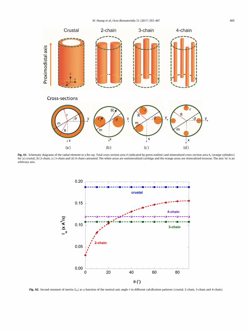
Fig. A1. Schematic diagrams of the radial element in a fin ray. Total cross section area A (indicated by green outline) and mineralized cross-section area Ac (orange cylinders)for (a) crustal, (b) 2-chain, (c) 3-chain and (d) 4-chain catenated. The white areas are unmineralized cartilage and the orange areas are mineralized tesserae. The axis ‘m’ is anarbitrary axis.
Fig. A2. Second moment of inertia (Im) as a function of the neutral axis angle h in different calcification patterns (crustal, 2-chain, 3-chain and 4-chain).
W. Huang et al. / Acta Biomaterialia 51 (2017) 393–407 405

Fig. A3. Second moment of inertia (Im) as a function calcification area (Ac/A) in different calcification patterns (crustal, 2-chain, 3-chain and 4-chain). Since Im depends on theneutral axis angle in 2-chain pattern, Im is plotted when h = 0� and 90�, which is the lower and upper limit, respectively.
406 W. Huang et al. / Acta Biomaterialia 51 (2017) 393–407
changes with position in the pectoral fin, this plot can provide abetter understanding of how the Im is not only a function of thechain pattern, but also of the calcification area.
References
[1] A.P. Farrell, E.D. Stevens, J.J. Cech, J.G. Richards, Encyclopedia of FishPhysiology: From Genome to Environment, Academic Press, an imprint ofElsevier, London; Waltham, MA, 2011.
[2] J.J. Videler, Fish Swimming, 1st ed., Chapman & Hall, London; New York, 1993.[3] S. Alben, P.G. Madden, G.V. Lauder, The mechanics of active fin-shape control
in ray-finned fishes, J. R. Soc. Interface 4 (13) (2007) 243–256.[4] G.S. Helfman, B.B. Collette, D.E. Facey, B.W. Bowen, The Diversity of Fishes:
Biology, Evolution, and Ecology, 2nd ed., Wiley-Blackwell, Chichester, UK,2009.
[5] M. Sfakiotakis, D.M. Lane, J.B.C. Davies, Review of fish swimming modes foraquatic locomotion, IEEE J. Oceanic Eng. 24 (2) (1999) 237–252.
[6] L.J. Rosenberger, Pectoral fin locomotion in batoid fishes: Undulation versusoscillation, J. Exp. Biol. 204 (2) (2001) 379–394.
[7] G.V. Lauder, Fish locomotion: Recent advances and new directions, Annu. Rev.Mar. Sci. 7 (2015) 521–545.
[8] R.S. Russo, S.S. Blemker, F.E. Fish, H. Bart-Smith, Biomechanical model of batoid(skates and rays) pectoral fins predicts the influence of skeletal structure on finkinematics: Implications for bio-inspired design, Bioinspiration Biomimetics10 (4) (2015) 046002.
[9] S.-J. Park, M. Gazzola, K.S. Park, S. Park, V. Di Santo, E.L. Blevins, J.U. Lind, P.H.Campbell, S. Dauth, A.K. Capulli, Phototactic guidance of a tissue-engineeredsoft-robotic ray, Science 353 (6295) (2016) 158–162.
[10] H. Ehrlich, Biological Materials of Marine Origin, Springer, New York, 2013.[11] J.T. Schaefer, A.P. Summers, Batoid wing skeletal structure: Novel
morphologies, mechanical implications, and phylogenetic patterns, J.Morphol. 264 (3) (2005) 298–313.
[12] T. Ørvig, Histologic studies of placotlerms and fossil elasmobranchs. I. Theendoskeleton, with remarks on the hard tissues of lower vertebrates ingeneral, Ark. Zoologi 2 (1951) 321–454.
[13] S.P. Applegate, A survey of shark hard parts, in: P.W. Gilbert, R.T. Mathewson,D.P. Rall (Eds.), Sharks, Skates and Rays, The Johns Hopkins Press, Baltimore,MD, 1967, pp. 37–67.
[14] N.E. Kemp, S.K. Westrin, Ultrastructure of calcified cartilage in theendoskeletal tesserae of sharks, J. Morphol. 160 (1) (1979) 75.
[15] M.L. Moss, Skeletal tissues in sharks, Am. Zool. 17 (2) (1977) 335–342.[16] J. Clement, Re-examination of the fine structure of endoskeletal mineralization
in Chondrichthyans: Implications for growth, ageing and calciumHomeostasis, Mar. Freshwater Res. 43 (1) (1992) 157–181.
[17] M. Egerbacher, M. Helmreich, E. Mayrhofer, P. Böck, Mineralisation of thehyaline cartilage in the small-spotted dogfish Scyliorhinus canicula L, ScriptaMedica (BRNO) 79 (2006) 199–212.
[18] M.N. Dean, C.G. Mull, S.N. Gorb, A.P. Summers, Ontogeny of the tessellatedskeleton: insight from the skeletal growth of the round stingray Urobatishalleri, J. Anat. 215 (3) (2009) 227–239.
[19] J.G. Maisey, The diversity of tessellated calcification in modern and extinctchondrichthyans, Rev. Paléobiol. 32 (2013) 355–371.
[20] R. Seidel, K. Lyons, M. Blumer, P. Zaslansky, P. Fratzl, J.C. Weaver, M.N. Dean,Ultrastructural and developmental features of the tessellated endoskeleton ofelasmobranchs (sharks and rays), J. Anat. 229 (2016) 681–702.
[21] D.O. Wagner, P. Aspenberg, Where did bone come from? An overview of itsevolution, Acta Orthopaedica 82 (4) (2011) 393–398.
[22] M.I. Coates, S.E.K. Sequeira, I.J. Sansom, M.M. Smith, Spines and tissues ofancient sharks, Nature 396 (6713) (1998) 729–730.
[23] X.X. Liu, M.N. Dean, A.P. Summers, J.C. Earthman, Composite model of theshark’s skeleton in bending: A novel architecture for biomimetic design offunctional compression bias, Mater. Sci. Eng., C 30 (8) (2010) 1077–1084.
[24] X.X. Liu, M.N. Dean, H. Youssefpour, A.P. Summers, J.C. Earthman, Stressrelaxation behavior of tessellated cartilage from the jaws of blue sharks, J.Mech. Behav. Biomed. Mater. 29 (2014) 68–80.
[25] P. Fratzl, O. Kolednik, F.D. Fischer, M.N. Dean, The mechanics of tessellations –bioinspired strategies for fracture resistance, Chem. Soc. Rev. 45 (2) (2016)252–267.
[26] M.N. Dean, A.P. Summers, Mineralized cartilage in the skeleton ofchondrichthyan fishes, Zoology 109 (2006) 164–168.
[27] M.N. Dean, S.N. Gorb, A.P. Summers, A cryoSEM method for presservation andvisualization of calcified shark cartilage (and other stubborn heterogeneousskeletal tissues), Microsc. Today 16 (2008) 48–50.
[28] S. Mulvaney, P.J. Motta, The morphology of the cephalic lobes and anteriorpectoral fins in six species of batoids, J. Morphol. 274 (2014) 1070–1083.
[29] M.A. Kolmann, D.R. Huber, M.N. Dean, R.D. Grubbs, Myological variability in adecoupled skeletal system: Batoid cranial anatomy, J. Morphol. 275 (8) (2014)862–881.
[30] M.N. Dean, L. Ekstrom, E. Monsonego-Ornan, J. Ballantyne, P.E. Witten, C. Riley,W. Habraken, S. Omelon, Mineral homeostasis and regulation ofmineralization processes in the skeletons of sharks, rays and relatives(Elasmobranchii), Semin. Cell Dev. Biol. 46 (2015) 51–57.
[31] M.R. Urist, Calcium and phosphrous in the blood and skeleton of theElasmobranchii, Endocrinology 69 (4) (1961) 778–801.
[32] M. Hamada, T. Nagai, N. Kai, Y. Tanoue, H. Mae, M. Hashimoto, K. Miyoshi, H.Kumagai, K. Saiki, Inorganic constituents of bone of fish, Fish. Sci. 61 (3) (1995)517–520.
[33] J.A. Freedman, D.L.G. Noakes, Why are there no really big bony fishes? A point-of-view on maximum body size in teleosts and elasmobranchs, Rev. Fish Biol.Fisheries 12 (4) (2002) 403–416.
[34] J.D. Currey, The design of mineralised hard tissues for their mechanicalfunctions, J. Exp. Biol. 202 (23) (1999) 3285–3294.
[35] C. Rath, B. Janto, J. Earl, A. Ahmed, F. Hu, L. Hiller, M. Dahlgren, R. Kreft, F. Yu, J.Wolff, H. Kweon, M. Christiansen, K. Hakansson, R. Williams, G. Ehrlich, D.Sherman, Meta-omic characterization of the marine invertebrate microbial

W. Huang et al. / Acta Biomaterialia 51 (2017) 393–407 407
consortium that produces the chemotherapeutic natural product ET-743, ACSChem. Biol. 6 (11) (2011) 1244–1256.
[36] T.J. Pedley, S.J. Hill, Large-amplitude undulatory fish swimming: Fluidmechanics coupled to internal mechanics, J. Exp. Biol. 202 (23) (1999) 3431–3438.
[37] F.J. Plantema, Sandwich Construction: The Bending and Buckling of SandwichBeams, Plates, and Shells, Wiley, New York, 1966.
[38] D. Zenkert, An Introduction to Sandwich Construction, Engineering MaterialsAdvisory Services, 1995.
[39] A.P. Summers, T.J. Koob, The evolution of tendon – morphology and materialproperties, Comp. Biochem. Physiol. A: Mol. Integr. Physiol. 133 (4) (2002)1159–1170.
[40] M.E. Porter, J.L. Beltran, T.J. Koob, A.P. Summers, Material properties andbiochemical composition of mineralized vertebral cartilage in seven
elasmobranch species (Chondrichthyes), J. Exp. Biol. 209 (15) (2006) 2920–2928.
[41] D.R. Huber, D.E. Neveu, C.M. Stinson, P.A. Anderson, I.K. Berzins, Mechanicalproperties of sand tiger shark (Carcharias taurus) vertebrae in relation to spinaldeformity, J. Exp. Biol. 216 (22) (2013) 4256–4263.
[42] M.E. Porter, J.H. Long, Vertebrae in compression: Mechanical behavior ofarches and centra in the gray smooth-hound shark (Mustelus californicus), J.Morphol. 271 (3) (2010) 366–375.
[43] C.A. Wilga, S.E. Diniz, P.R. Steele, J. Sudario-Cook, E.R. Dumont, L.A. Ferry,Ontogeny of feeding mechanics in smoothhound sharks: morphology andcartilage stiffness, Integr. Comp. Biol. 56 (3) (2016) 442–448.
[44] H.W. Courtland, G.M. Wright, R.G. Root, M.E. DeMont, Comparativeequilibrium mechanical properties of bovine and lamprey cartilaginoustissues, J. Exp. Biol. 206 (8) (2003) 1397–1408.