structure, molecular orientation, and resultant mechanical ... · pdf filestructure, molecular...
TRANSCRIPT
at SciVerse ScienceDirect
Polymer 53 (2012) 791e800
Contents lists available
Polymer
journal homepage: www.elsevier .com/locate/polymer
Structure, molecular orientation, and resultant mechanical properties in core/sheath poly(lactic acid)/polypropylene composites
Sara A. Arvidson a, Ka C. Wong b,c, Russell E. Gorga d,*, Saad A. Khan a,**
aDepartment of Chemical and Biomolecular Engineering, Campus Box 7905, North Carolina State University, Raleigh, NC 27695, USAbDepartment of Materials Science and Engineering, Campus Box 7907, North Carolina State University, Raleigh, NC 27695, USAcAnalytical Instrumentation Facility, Campus Box 7531, North Carolina State University, Raleigh, NC 27695, USAdDepartment of Textile Engineering, Chemistry and Science, Campus Box 8301, North Carolina State University, Raleigh, NC 27695, USA
a r t i c l e i n f o
Article history:Received 2 September 2011Received in revised form15 December 2011Accepted 17 December 2011Available online 21 December 2011
Keywords:PolypropylenePoly(lactic acid)Core/sheath fiber
* Corresponding author. Tel.: þ1 919 515 6553; fax** Corresponding author. Tel.: þ1 919 515 4519; fax:
E-mail addresses: [email protected], [email protected] (S.A. Khan).
0032-3861/$ e see front matter � 2011 Elsevier Ltd.doi:10.1016/j.polymer.2011.12.042
a b s t r a c t
We study the coaxial spinning of poly(lactic acid) (PLA) with polypropylene (PP) in a core/sheathconfiguration. PPcore/PLAsheath and PLAcore/PPsheath fibers maintain the high breaking strength that PP andPLA exhibit individually, showing marked improvement in strength over previous reports of PP/PLAblend fibers. Crystalline morphologies are greatly affected by the location within the fiber (i.e., core,sheath, or spun individually), and hence, co-spinning provides a route to tailor the morphology and fiberdiameter beyond that available with single component fibers. A new approach to estimate molecularorientation of core sheath fibers based on the tensile response of the fiber is developed, and indicatesthat co-spinning PP with PLA results in a synergistic effect with increases in the molecular orientationabove that which is possible with spinning either PP or PLA individually.
� 2011 Elsevier Ltd. All rights reserved.
1. Introduction
Polymer composites are increasingly important for structuralbuilding [1e4], electronic [5e7] and biomedical materials [8,9]. Anideal composite is one that benefits from a net increase in theperformance of the material derived from the desirable character-istics of the constituent polymers and interactions between them,with suppression of unfavorable traits of each constituent. Themechanical behavior of semicrystalline polymers is stronglydependent on crystallinity and microstructure, which are deter-mined by the thermomechanical history. However, co-processingtwo (or more) polymers provides additional challenges incontrolling and predicting the material behavior. To create a poly-merepolymer composite, the materials must be compatible interms of the conditions at which they can be processed as well asthe conditions at which each exhibits its desired property (e.g.,toughness, conductivity, optical), as well as strong consideration ofinterfacial compatibility.
With recent focus on environmental awareness, much consid-eration has been given to polymer composites that include all or
: þ1 919 515 6532.þ1 919 515 [email protected] (R.E. Gorga),
All rights reserved.
some fraction of materials that can be produced from sustainableresources such as bamboo [10], cotton [11], hemp [12], jute [13],kenaf [14], linseed and caster oil [15] and poly(lactic acid) [13,16,17].Polymers of lactic acid or lactide monomer (PLA), which can beproduced from agricultural rather than petroleum raw materials,are particularly interesting for biomedical, packaging, and dispos-able applications. PLAs are biodegradable and biocompatible andmay solve some solid waste disposal problems. Manufacturing PLAconsumes up to 65% less fossil fuel and produces up to 80e90% lessgreenhouse gas emissions relative to petroleum-based polymers[18] and are currently in use for sutures and other medical devicesand increasingly in food packaging in Japan, the US, and Europe[19]. Yet, despite high tensile strength and the potential environ-mental advantages (outlined above), PLA has found limited use dueto its brittleness and low ductility [20], poor gas barrier properties[21] and hydrolysis at temperatures suitable for melt processing,dyeing, or laundering [22e24].
Unlike PLA, polypropylene (PP) is not biodegradable orbiocompatible, but possesses superior mechanical strength, abra-sion resistance, resistance to chemical or biological agents, andbenefits from being a ubiquitous and inexpensive leader innumerous polymer applications including woven and nonwovenfibers, extrusion molding, and packaging. Excellent quality extru-dates such as fibers, films, and molded parts may be produced fromPP alone, though the lack of reactive sites and low surface energyhas lead to a number of creative methods to increase PP
S.A. Arvidson et al. / Polymer 53 (2012) 791e800792
functionality. Additives may impart antimicrobial activity [25e27].Some recent post-spinning treatments to PP fibers such as plasmaexposure [28,29], chemical modification [28,30e32], or metal ormetal oxide deposition [33,34] have been applied to increase thereactivity, conductivity, abrasion resistance, or wettability of thesurface though possible drawbacks to these approaches includechanges in morphology, loss of polymer mechanical strength, andincrease in web permeability when additives are included [35,36]and high processing temperatures, high cost, and/or low effi-ciency [28] for many of the post-spinning treatments.
In this work we focus on composite PLA e PP fibers produced byco-extrusion with the ultimate goal of improving the mechanicalproperties over that of PP-PLA blends, providing a better under-standing the effect of co-extrusion on the morphology of eachpolymer, and ultimately insight into the design of other polymercomposite structures. We use fibers as our system of study becauseof their preponderance in composite applications. In addition, theability to examine the role of core versus sheath materials wouldprovide insight in multilayered fibrous systems, which a study ofa bilayered planar composite system would fail to achieve.Bicomponent fibers are widely used in nonwoven fiber materialswhere the sheath has a lower melting point to promote bonding[37,38] while the higher Tm core component experiences lessthermal exposure and morphological modifications duringbonding. Beyond the expressed advantages of PP and PLA alreadydiscussed, both polymers melt and can be processed within thesame range of temperatures (Tmelt ¼ 155e165 �C,Tprocess ¼ 200e230 �C), which is markedly lower than that for othercommon fiber forming polymers such as nylon-6 or poly(ethyleneterephthalate). There are a number of reports of bicomponentspinning and bicomponent PP-PLA fibers have recently beencommercialized [39], but to our knowledge, no reports in the openliterature describe the melt spinning process for core/sheathbicomponent PLA with PP fibers nor the effect of spinning param-eters on morphology of such fibers.1 While blending PLA with PPlead to decreased fiber strength relative to either polymer spunindividually due to poor interfacial compatibility [40,41], webelieve that greatly reducing interfacial contact area in core-sheathconfiguration, where each polymer is continuous along the lengthof the fiber, will maintain the mechanics of the stronger compo-nent. Further, co-spinning a sheath of PLA on PP provides routes tosurface-functionalize PP [36e38,41e43] fibers for biological andfiltration applications, while encapsulating PLA within a sheath ofPP can provide for resistance to solvent or biological degradation.
2. Experimental
2.1. Materials and fiber spinning
Isotactic polypropylene and poly(lactic acid) were provided bySunoco Chemicals Polymers Division, Pittsburg, PA (productCP360H) and NatureWorks� LLC, Minnetonka, MN (product PLA
1 Liu, Y.; Tovia, F.; Pierce, J. Textile Research Journal 2009 79, 566e573 describesthe consumer acceptance of scented scarves knitted from melt-spun PP/PLAbicomponent fibers. However due to “a confidentiality agreement with FiberInnovation Technology of Johnson City, Tennessee”, melt spinning temperatures,mass flow rate, velocity, or other details of the fiber formation or characterizationwere not addressed. US patent 2011/0028062 describes core-sheath fibers manu-factured into nonwoven materials with PLA and the majority component of the coreand a polyolefin such as PP as the majority component of the sheath of fibers. Theemphasis of the patent is creating biodegradable nonwovens of polyolefin sheath-PLA core fibers. No mention is given on the spinning conditions (temperatures,mass flow rate, velocity, or other details of the fiber formation or characterization).Degradation and tensile properties are reported for nonwovens but not for indi-vidual fibers.
polymer 6202D, 98% L-lactide), respectively. Polymer viscositiesare listed in Table 1. Single and bicomponent fibers were spun atthe Nonwovens Cooperative Research Center (NCRC) Partners’Pilot Spunbond line located at North Carolina State University(NCSU) over a range of aspirator pressures.2 Confluence of themolten PLA and PP occurred in the spin pack. Below the spinpack, the filaments were directed through the quench zone tothe attenuation zone, where the aspirator pressure controlledthe air velocity surrounding the fibers and effectively the fiberspinning velocity. Fibers were collected following extrusion butwithout being bonded into a web so that the as-spunmorphology could be studied. All fibers were spun with a totalmass throughput of 0.4 g$hole�1 min�1. Fibers collected for eachcore/sheath configuration without the use of aspirator pressureare referred to as “freefall” fibers with an approximate spinningvelocity of 20 m$min�1. Fiber diameters (D) (n z 20) are used tocalculate the velocity at the point where fibers solidifiedaccording to
V ¼ QrAc
(1)
which is reported as the “spinning velocity” V. In Eq. (1), Q isthe polymer throughput per spinneret hole (g min�1), r is thefiber density (g m�3), and Ac is the cross sectional area of thefiber (m2).
2.2. Wide angle X-ray diffraction
Wide angle X-ray diffraction (WAXD) studies were conductedwith a CuKa radiation source (l ¼ 1.542 Å) at 40 kV � 30 mA for1800s on a Bruker D-5000 diffractometer (Madison, WI) equippedwith a Highstar area detector. Diffraction patterns were analyzedwith Bruker General Area Detector Diffraction System (GADDS)software. Fibers were aligned and placed in the apparatus orientedvertically, with the plane of the fibers perpendicular to the x-raybeam. In transmission mode, the intensity was recorded for 2q inthe range of 10� to 32�. Scans taken with an empty sample holderserved as a background for subtraction.
2.3. Differential scanning calorimetry
Differential scanning calorimetry (DSC) was performed usinga TA Instruments Q2000 model differential scanning calorimeter.Scans were carried out on 6e12 mg samples in standard aluminumpans calibrated to an indium standard. Heating rates, unlessotherwise specified, were 10 �C$min�1 under 50 mL$min�1 N2purge.
2.4. Mechanical testing
Mechanical testing of fibers was conducted on an Instron model5544 (Norwood, MA) fitted with 0.9 cm clamps and a 5 N load cellat ambient conditions and analyzed with Bluehill v. 2 software.Single filaments with a gage length of 28.6 mm were drawn ata crosshead speed of 25.4 mm/min. For calculating true stress,a constant volume cylinder is assumed.
2 Spunbonding is a method of producing nonwovens by depositing extruded,spun filaments onto a collection belt. Filaments are randomized onto the collectionbelt by air jets, which create a web that is subsequently bonded using heated rolls.In this study, melt-spun and spunbond processes differ in the method of controllingfiber take-up velocity: melt-spun fibers utilize a winder while spunbondingemploys air jets to draw fibers. Using air jets in spunbonding has the consequenceof changing the cooling rate of the molten polymer.
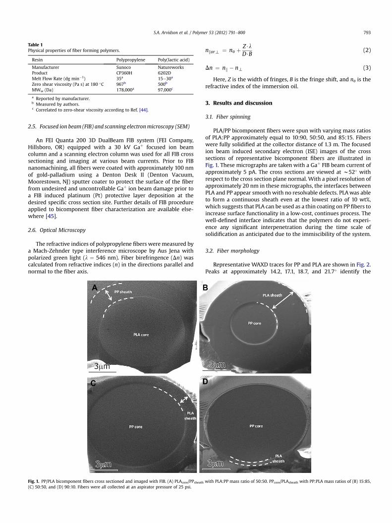
Table 1Physical properties of fiber forming polymers.
Resin Polypropylene Poly(lactic acid)
Manufacturer Sunoco NatureworksProduct CP360H 6202DMelt Flow Rate (dg min�1) 35a 15e30a
Zero shear viscosity (Pa s) at 180 �C 967b 500b
MWw (Da) 178,000a 97,000c
a Reported by manufacturer.b Measured by authors.c Correlated to zero-shear viscosity according to Ref. [44].
S.A. Arvidson et al. / Polymer 53 (2012) 791e800 793
2.5. Focused ion beam (FIB) and scanning electronmicroscopy (SEM)
An FEI Quanta 200 3D DualBeam FIB system (FEI Company,Hillsboro, OR) equipped with a 30 kV Gaþ focused ion beamcolumn and a scanning electron column was used for all FIB crosssectioning and imaging at various beam currents. Prior to FIBnanomachining, all fibers were coated with approximately 100 nmof gold-palladium using a Denton Desk II (Denton Vacuum,Moorestown, NJ) sputter coater to protect the surface of the fiberfrom undesired and uncontrollable Gaþ ion beam damage prior toa FIB induced platinum (Pt) protective layer deposition at thedesired specific cross section site. Further details of FIB procedureapplied to bicomponent fiber characterization are available else-where [45].
2.6. Optical Microscopy
The refractive indices of polypropylene fibers were measured bya Mach-Zehnder type interference microscope by Aus Jena withpolarized green light (l ¼ 546 nm). Fiber birefringence (Dn) wascalculated from refractive indices (n) in the directions parallel andnormal to the fiber axis.
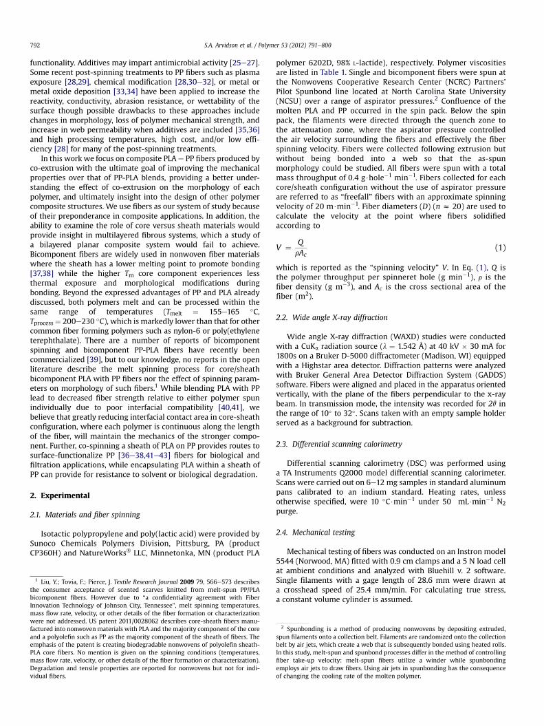
Fig. 1. PP/PLA bicomponent fibers cross sectioned and imaged with FIB. (A) PLAcore/PPsheath(C) 50:50, and (D) 90:10. Fibers were all collected at an aspirator pressure of 25 psi.
nkort ¼ no þ Z$lD$B
(2)
Dn ¼ nk � nt (3)
Here, Z is the width of fringes, B is the fringe shift, and no is therefractive index of the immersion oil.
3. Results and discussion
3.1. Fiber spinning
PLA/PP bicomponent fibers were spun with varying mass ratiosof PLA:PP approximately equal to 10:90, 50:50, and 85:15. Fiberswere fully solidified at the collector distance of 1.3 m. The focusedion beam induced secondary electron (ISE) images of the crosssections of representative bicomponent fibers are illustrated inFig. 1. These micrographs are taken with a Gaþ FIB beam current ofapproximately 5 pA. The cross sections are viewed at w52� withrespect to the cross section plane normal. With a pixel resolution ofapproximately 20 nm in these micrographs, the interfaces betweenPLA and PP appear smooth with no resolvable defects. PLAwas ableto form a continuous sheath even at the lowest ratio of 10 wt%,which suggests that PLA can be used as a thin coating on PP fibers toincrease surface functionality in a low-cost, continues process. Thewell-defined interface indicates that the polymers do not experi-ence any significant interpenetration during the time scale ofsolidification as anticipated due to the immiscibility of the system.
3.2. Fiber morphology
Representative WAXD traces for PP and PLA are shown in Fig. 2.Peaks at approximately 14.2, 17.1, 18.7, and 21.7� identify the
with PLA:PP mass ratio of 50:50. PPcore/PLAsheath with PP:PLA mass ratios of (B) 15:85,
8 10 12 14 16 18 20 22 24 26
Inte
nsity
(a
.u.)
2θ (deg)
PLA 56 m/min
PLA 4200 m/min
PP 500 m/min
PP 20 m/min
Fig. 2. Representative WAXD patterns PP and PLA fibers collected at selected spinningvelocities.
Table 2Polymer morphology and spinning velocity with changing core/sheath polymer andaspirator pressure for 50 wt% core/50 wt% sheath fibers. “Trace” indicates that thereare only trace amounts of the crystalline material present by XRD. The highestaspirator pressure for each configuration indicates the maximum pressure at whichgood quality fibers could be obtained.
Core/SheathPolymer
AspiratorPressure(PSI)
SpinningVelocity(m/min)
Crystalline Morphologya
PP PLA
1 PP/PP 0 15 crystalline e
2 PP/PP 8 1570 crystalline,mesomorphic
e
3 PP/PP 10 2010 crystalline e
4 PP/PP 15 2120 crystalline e
5 PP/PP 18 2280 crystalline e
6 PP/PP 25 2560 crystalline e
7 PLA/PP 0 21 crystalline8 PLA/PP 15 2370 mesomorphic9 PLA/PP 20 2670 mesomorphic10 PLA/PP 25 2820 crystalline crystalline11 PLA/PP 30 3180 crystalline crystalline12 PLA/PP 35 3210 crystalline crystalline
13 PP/PLA 0 35 crystalline,mesomorphic
14 PP/PLA 5 821 crystalline,mesomorphic
15 PP/PLA 10 1970 mesomorphic16 PP/PLA 15 2850 crystalline17 PP/PLA 20 3200 mesomorphic crystalline18 PP/PLA 25 3510 trace crystalline,
mesomorphiccrystalline
19 PP/PLA 30 4260 mesomorphic crystalline20 PP/PLA 35 5260 crystalline21 PP/PLA 40 4830 trace crystalline,
mesomorphic
22 PLA/PLA 0 56 e
23 PLA/PLA 5 762 e
24 PLA/PLA 10 1910 e
25 PLA/PLA 15 2300 e
26 PLA/PLA 20 2270 e
27 PLA/PLA 25 2470 e trace crystalline28 PLA/PLA 30 2770 e
29 PLA/PLA 35 2940 e crystalline30 PLA/PLA 40 4190 e crystalline
a Note in all cases, PP and PLA contained some amorphous material. Only thecrystal or mesomorphic morphologies, if present, are listed.
10 20 30 40
10
20
Fibe
r Dia
met
er (μ
m)
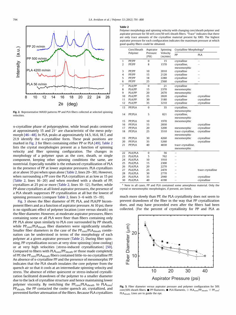
Aspirator Pressure (psi)Fig. 3. Fiber diameter versus aspirator pressure and polymer configuration for 50%core/50% sheath fibers. - PP filaments, C PLA filaments, > PLAcore/PPsheath, P PPcore/PLAsheath. Lines are to guide the eye.
S.A. Arvidson et al. / Polymer 53 (2012) 791e800794
a-crystalline phase of polypropylene, while broad peaks centeredat approximately 15 and 21� are characteristic of the meso poly-morph [46e48]. In PLA, peaks at approximately 14.5, 16.6, 18.7, and21.9 identify the a-crystalline form. These peak positions aremarked in Fig. 2 for fibers containing either PP or PLA [49]. Table 2lists the crystal morphologies present as a function of spinningvelocity and fiber spinning configuration. The changes inmorphology of a polymer spun as the core, sheath, or singlecomponent, keeping other spinning conditions the same, arenontrivial. Especially notable is the enhanced crystallization of PLAin the presence of PP at lower aspirator pressures. PLA crystallizesat or above 35 psi when spun alone (Table 2, lines 29e30). However,when surrounding a PP core the PLA crystallizes at as low as 15 psi(Table 2, lines 16e20) and when enrobed with a sheath of PP,crystallizes at 25 psi or more (Table 2, lines 10e12). Further, whilePP alone crystallizes at all listed aspirator pressures, the presence ofa PLA sheath suppresses PP crystallization at all but the lowest ofspinning pressures (compare Table 2, lines 3e6 with 15e19).
Fig. 3 shows the fiber diameter of PP, PLA, and PLA/PP bicom-ponent fibers and as a function of aspirator pressure. At 10 psi, thereis no significant effect of polymer location (core versus sheath) onthe fiber diameter. However, at moderate aspirator pressures, fiberscontaining some or all PLA were finer than fibers containing onlyPP. PLA alone spun similarly to PLA core surrounded by PP sheath,while PPcore/PLAsheath fiber diameters were significantly smaller.Smaller fiber diameters in the case of the PPcore/PLAsheath combi-nation can be understood in terms of the morphology of eachpolymer at a given aspirator pressure (Table 2). During fiber spin-ning, PP crystallization occurs at very slow spinning (slow cooling)or at very high velocities (stress-induced crystallization) [50].Compared to fibers with PLAcore/PPsheath or those made completelyof PP, the PPcore/PLAsheath fibers contained little-to-no crystalline PP.An absence of a-crystalline PP and the presence of mesomorphic PPindicates that the PLA sheath insulates the core polymer from thequench air so that it cools at an intermediate spinning velocity andstress. The absence of either quiescent or stress-induced crystalli-zation facilitated drawdown of the polymer to a smaller diameterdue to the lack of crystalline structure and hencemaintaining lowerpolymer viscosity. By switching the PPcore/PLAsheath to PLAcore/PPsheath, the PP contacted the cooler quench air, crystallized, andprevented further attenuation of the fibers. Because PLA crystallizes
much more slowly than PP, the PLA crystallinity does not seem toprevent drawdown of the fiber in the way that PP crystallizationdoes, and may have proceeded even after the fibers had beencollected. (For the percent of crystallinity for PP and PLA as
S.A. Arvidson et al. / Polymer 53 (2012) 791e800 795
a function of annealing time, showing the relatively slow crystal-lization of PLA compared to PP, see Supplementary MaterialFigure S-1. It is germane to note that DSC was performed on indi-vidual and bicomponent fibers. However, due to the overlap formelting peaks for both PLA and PP near 165 �C, this data cannot beused to discern crystallinity fractions for each component. There-fore, onlyWAXD is used to calculate crystallinity. For completeness,the DSC thermograms are included in the Supplementary MaterialFigure S-2.)
In many melt spinning models, knowledge of the percent ofeach phase present (amorphous and crystallizing) is requiredbecause phases are treated separately in terms of their contribu-tions to heat capacity, crystallization, and resistance to deformationto name just a few [51,52]. For the case where a third (i.e., meso-morphic or pseudocrystalline) phase is present, it is unclear if themesophase should be included with the amorphous phase, crys-talline phase, or as a distinct phase. Online XRD measurementshave shown that the mesomorphic structure may already bepresent during spinning [53] and several studies have shown thatthe mesomorphic (“smectic”) form of PP can be present both aboveand below the Tm of the polymer undergoing shear, a featureunique to PP [54]. Our data show that when the mesophase ispresent and the crystalline phase is absent in PP fibers, fibersexhibit higher spinning velocities at a given aspirator pressure,which corresponds to smaller diameters and further drawdown(Compare Table 2 and Fig. 3). The implications are that in themoltenstate, the mesomorphic structure did not perform crystal-likefunctions in terms of arresting fiber attenuation throughincreasing the elongational viscosity and leading to solidification.Because the mesomorphic fraction does not contribute to thecrystallizing phase of the extruded melt, in melt spinning modelsand simulations that include two ormore phases, themesomorphicphase should be treated as an organized amorphous phase. Incontrast, in the solid state, the mesomorphic phase has been shownto provide “network junctions” that tie amorphous “flexible chains”in the same manner as a true crystalline phase [55].
3.3. Tensile properties of bicomponent fibers
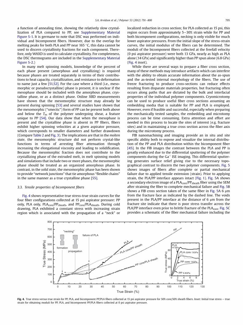
Fig. 4 shows representative true stress-true strain curves for thefour fiber configurations collected at 15 psi aspirator pressure: PPonly, PLA only, PLAcore/PPsheath, and PPcore/PLAsheath. During colddrawing, PLA exhibited a constant stress with increasing strainregion which is associated with the propagation of a “neck” or
0 10 20 30 40 50 60
0
100
200
300
400
500
600
700
800
"necking"failure of PLA
propagation
True
Stre
ss (M
Pa)
True S
formation
PL
PLA c
Fig. 4. True stress versus true strain for PP, PLA, and bicomponent PP/PLA fibers collected atstrain for obtaining moduli for PP, PLA, and bicomponent PP/PLA fibers collected at 0 psi a
localized reduction in cross section; for PLA collected as 15 psi, thisregion occurs from approximately 5e30% strain while for PP andboth bicomponent configurations, necking is only visible for muchlower aspirator pressures. From the initial slope of the stress-straincurves, the initial modulus of the fibers can be determined. Themoduli of the bicomponent fibers collected at the freefall velocity(0 psi aspirator pressure) were both 13 GPa, nearly as high as PLAalone (14 GPa) and significantly higher than PP spun alone (6.8 GPa)(Fig. 4 inset).
While there are several ways to prepare a fiber cross section,many of these methods may introduce artifacts which can interferewith the ability to obtain accurate information about the as-spunand the as-tested internal morphology of the fibers. The use offreeze fracturing to produce cross-sections can reduce effectsresulting from disparate materials properties, but fracturing oftenoccurs along paths that are dictated by the bulk and interfacialproperties of the individual polymer components. Cryomicrotomycan be used to produce useful fiber cross sections assuming anembedding media that is suitable for PP and PLA is employed.However, even if feasible and successful, especially when preparingthe mechanically tested samples, the embedding and microtomyprocess can be time consuming. Extra attention and effort areneeded in this process to locate the sites of interest (e.g. fracturesites) and in maintaining a true cross section across the fiber axisduring the microtomy process.
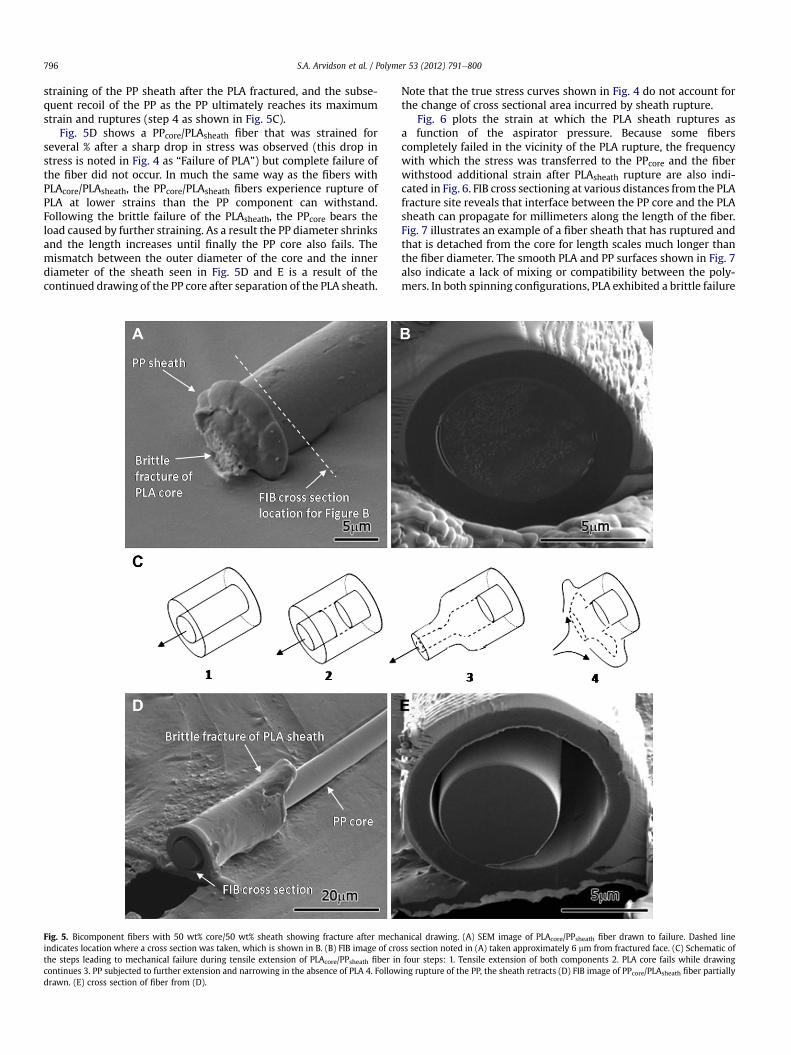
FIB nanomachining and imaging provide an in situ and sitespecific ability both to expose and visualize the internal distribu-tion of the PP and PLA distribution within the bicomponent fiber[45]. In the FIB images the contrast between the PLA and PP isgreatly enhanced due to the differential sputtering of the polymercomponents during the Gaþ ISE imaging. This differential sputter-ing generates surface relief giving rise to the necessary topo-graphical contrast to discern the two polymer components. Fig. 5shows images of fibers after complete or partial mechanicalfailure due to applied tensile extension (strain). Prior to applyingstrain, the PLA/PP interface appears intact (Fig. 1). Fig. 5A showsa secondary electron image of a PLAcore/PPsheath fiber using the SEMafter straining the fiber to complete mechanical failure and Fig. 5Bshows a FIB cross section taken of the same fiber in Fig. 5A 6 mmfrom the fracture face as indicated by the dashed line. The voidspresent in the PLA/PP interface at the distance of 6 mm from thefracture site indicate that there is poor stress transfer across thePLA/PP interface even prior to brittle fracture of the PLAcore. Fig. 5Cprovides a schematic of the fiber mechanical failure including the
70 80 90 100 110 120 130
0 2 4 6 80
20
40
60
PP core 13GPa
PP 6.8GPa
PP
14 GPa
train (%)
A
ore/PP sheath
PP core/PLA sheath
PLA
PLA core 13GPa
True
stre
ss (M
Pa)
True strain (%)
15 psi aspirator pressure for 50% core/50% sheath fibers. Inset: Initial true stress e truespirator pressure.
S.A. Arvidson et al. / Polymer 53 (2012) 791e800796
straining of the PP sheath after the PLA fractured, and the subse-quent recoil of the PP as the PP ultimately reaches its maximumstrain and ruptures (step 4 as shown in Fig. 5C).
Fig. 5D shows a PPcore/PLAsheath fiber that was strained forseveral % after a sharp drop in stress was observed (this drop instress is noted in Fig. 4 as “Failure of PLA”) but complete failure ofthe fiber did not occur. In much the same way as the fibers withPLAcore/PLAsheath, the PPcore/PLAsheath fibers experience rupture ofPLA at lower strains than the PP component can withstand.Following the brittle failure of the PLAsheath, the PPcore bears theload caused by further straining. As a result the PP diameter shrinksand the length increases until finally the PP core also fails. Themismatch between the outer diameter of the core and the innerdiameter of the sheath seen in Fig. 5D and E is a result of thecontinued drawing of the PP core after separation of the PLA sheath.
Fig. 5. Bicomponent fibers with 50 wt% core/50 wt% sheath showing fracture after mechindicates location where a cross section was taken, which is shown in B. (B) FIB image of crothe steps leading to mechanical failure during tensile extension of PLAcore/PPsheath fiber incontinues 3. PP subjected to further extension and narrowing in the absence of PLA 4. Followdrawn. (E) cross section of fiber from (D).
Note that the true stress curves shown in Fig. 4 do not account forthe change of cross sectional area incurred by sheath rupture.
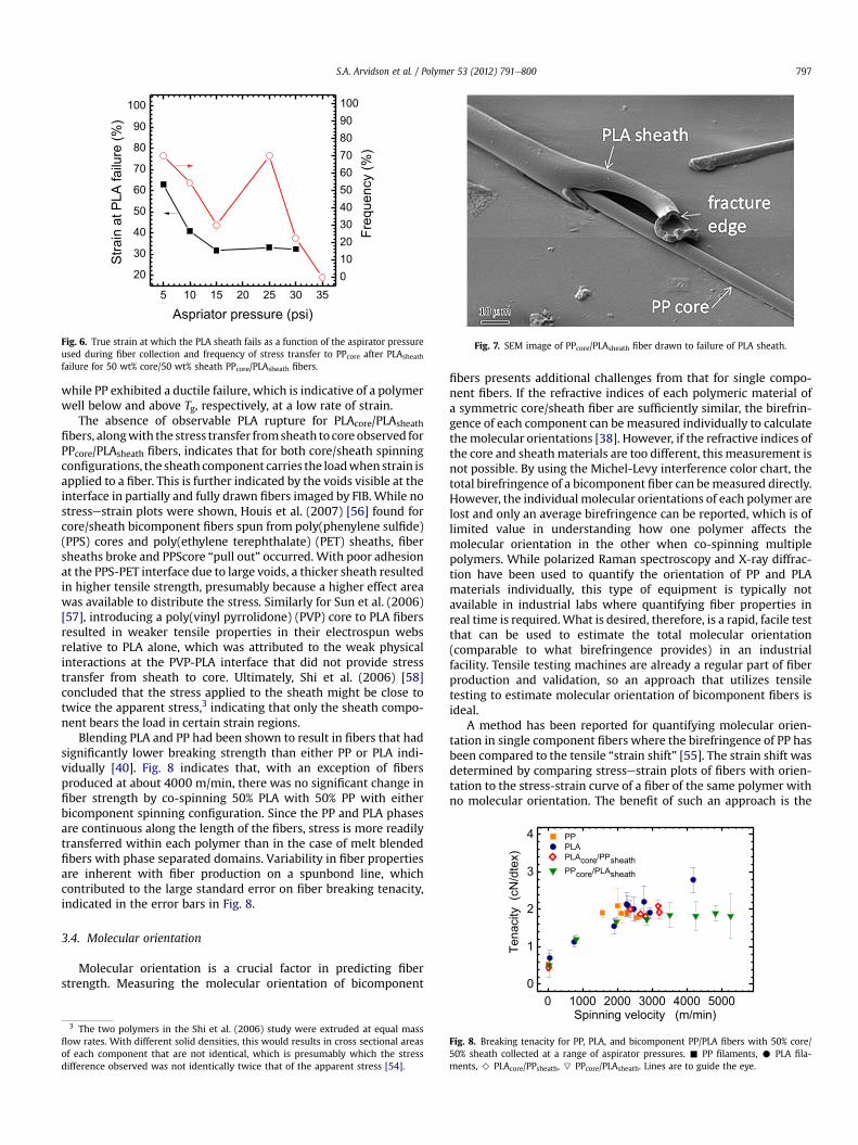
Fig. 6 plots the strain at which the PLA sheath ruptures asa function of the aspirator pressure. Because some fiberscompletely failed in the vicinity of the PLA rupture, the frequencywith which the stress was transferred to the PPcore and the fiberwithstood additional strain after PLAsheath rupture are also indi-cated in Fig. 6. FIB cross sectioning at various distances from the PLAfracture site reveals that interface between the PP core and the PLAsheath can propagate for millimeters along the length of the fiber.Fig. 7 illustrates an example of a fiber sheath that has ruptured andthat is detached from the core for length scales much longer thanthe fiber diameter. The smooth PLA and PP surfaces shown in Fig. 7also indicate a lack of mixing or compatibility between the poly-mers. In both spinning configurations, PLA exhibited a brittle failure
anical drawing. (A) SEM image of PLAcore/PPsheath fiber drawn to failure. Dashed liness section noted in (A) taken approximately 6 mm from fractured face. (C) Schematic offour steps: 1. Tensile extension of both components 2. PLA core fails while drawinging rupture of the PP, the sheath retracts (D) FIB image of PPcore/PLAsheath fiber partially
5 10 15 20 25 30 35
20
30
40
50
60
70
80
90
100)
%(eruliaf
ALPtaniartS
Aspriator pressure (psi)
Freq
uenc
y (%
)
0102030405060708090100
Fig. 6. True strain at which the PLA sheath fails as a function of the aspirator pressureused during fiber collection and frequency of stress transfer to PPcore after PLAsheath
failure for 50 wt% core/50 wt% sheath PPcore/PLAsheath fibers.
Fig. 7. SEM image of PPcore/PLAsheath fiber drawn to failure of PLA sheath.
0
1
2
3
4
Tena
city
(cN
/dte
x)
PP PLA PLAcore/PPsheath PPcore/PLAsheath
S.A. Arvidson et al. / Polymer 53 (2012) 791e800 797
while PP exhibited a ductile failure, which is indicative of a polymerwell below and above Tg, respectively, at a low rate of strain.
The absence of observable PLA rupture for PLAcore/PLAsheathfibers, alongwith the stress transfer fromsheath to coreobserved forPPcore/PLAsheath fibers, indicates that for both core/sheath spinningconfigurations, the sheath component carries the loadwhenstrain isapplied to a fiber. This is further indicated by the voids visible at theinterface in partially and fully drawn fibers imaged by FIB. While nostressestrain plots were shown, Houis et al. (2007) [56] found forcore/sheath bicomponent fibers spun from poly(phenylene sulfide)(PPS) cores and poly(ethylene terephthalate) (PET) sheaths, fibersheaths broke and PPScore “pull out” occurred. With poor adhesionat the PPS-PET interface due to large voids, a thicker sheath resultedin higher tensile strength, presumably because a higher effect areawas available to distribute the stress. Similarly for Sun et al. (2006)[57], introducing a poly(vinyl pyrrolidone) (PVP) core to PLA fibersresulted in weaker tensile properties in their electrospun websrelative to PLA alone, which was attributed to the weak physicalinteractions at the PVP-PLA interface that did not provide stresstransfer from sheath to core. Ultimately, Shi et al. (2006) [58]concluded that the stress applied to the sheath might be close totwice the apparent stress,3 indicating that only the sheath compo-nent bears the load in certain strain regions.
Blending PLA and PP had been shown to result in fibers that hadsignificantly lower breaking strength than either PP or PLA indi-vidually [40]. Fig. 8 indicates that, with an exception of fibersproduced at about 4000 m/min, there was no significant change infiber strength by co-spinning 50% PLA with 50% PP with eitherbicomponent spinning configuration. Since the PP and PLA phasesare continuous along the length of the fibers, stress is more readilytransferred within each polymer than in the case of melt blendedfibers with phase separated domains. Variability in fiber propertiesare inherent with fiber production on a spunbond line, whichcontributed to the large standard error on fiber breaking tenacity,indicated in the error bars in Fig. 8.
3.4. Molecular orientation
Molecular orientation is a crucial factor in predicting fiberstrength. Measuring the molecular orientation of bicomponent
3 The two polymers in the Shi et al. (2006) study were extruded at equal massflow rates. With different solid densities, this would results in cross sectional areasof each component that are not identical, which is presumably which the stressdifference observed was not identically twice that of the apparent stress [54].
fibers presents additional challenges from that for single compo-nent fibers. If the refractive indices of each polymeric material ofa symmetric core/sheath fiber are sufficiently similar, the birefrin-gence of each component can be measured individually to calculatethemolecular orientations [38]. However, if the refractive indices ofthe core and sheathmaterials are too different, this measurement isnot possible. By using the Michel-Levy interference color chart, thetotal birefringence of a bicomponent fiber can bemeasured directly.However, the individual molecular orientations of each polymer arelost and only an average birefringence can be reported, which is oflimited value in understanding how one polymer affects themolecular orientation in the other when co-spinning multiplepolymers. While polarized Raman spectroscopy and X-ray diffrac-tion have been used to quantify the orientation of PP and PLAmaterials individually, this type of equipment is typically notavailable in industrial labs where quantifying fiber properties inreal time is required.What is desired, therefore, is a rapid, facile testthat can be used to estimate the total molecular orientation(comparable to what birefringence provides) in an industrialfacility. Tensile testing machines are already a regular part of fiberproduction and validation, so an approach that utilizes tensiletesting to estimate molecular orientation of bicomponent fibers isideal.
A method has been reported for quantifying molecular orien-tation in single component fibers where the birefringence of PP hasbeen compared to the tensile “strain shift” [55]. The strain shift wasdetermined by comparing stressestrain plots of fibers with orien-tation to the stress-strain curve of a fiber of the same polymer withno molecular orientation. The benefit of such an approach is the
0 1000 2000 3000 4000 5000Spinning velocity (m/min)
Fig. 8. Breaking tenacity for PP, PLA, and bicomponent PP/PLA fibers with 50% core/50% sheath collected at a range of aspirator pressures. - PP filaments, C PLA fila-ments, > PLAcore/PPsheath, P PPcore/PLAsheath. Lines are to guide the eye.
0 10 20 30 400.00
0.01
0.02
0.03Bi
refri
ngen
ce Δ
n Bi
refri
ngen
ce Δ
n
0 50 100 1500.00
0.01
0.02
0.03
Strain shift ΔεT (%)
Aspirator pressure (psi)
B
A
Fig. 9. A) Birefringence for PP and PLA single component fibers. (B) Birefringencecorrelated to tensile strain shift for PP and PLA single component fibers. , PP fila-ments, C PLA filaments.
0
200
400
600
800
1000
1200
-50 0 50 100
0
200
400
600
800
1000
1200
True
Stre
ss (M
Pa)
PLA master curve
True
Stre
ss (M
Pa)
True
PP master curve
0 1000 2000 3000 4000 50000
20
40
60
80
100
120
PLAPPcore/PLAsheath
Stra
in s
hift
(%)
Spinning velocity (m/min)
Stra
in s
hift
(%)
0 1000 2000 3000 4000 50000
50
100
150
200
250
300
PPPLAcore/PPsheath
Spinning velocity (m/min)
A
B
Fig. 10. Overlaying bicomponent fiber true stress-true strain profiles with (A) PLA and (B) PPfibers.
S.A. Arvidson et al. / Polymer 53 (2012) 791e800798
ease of tensile measurements relative to other methods available.Once the relationship between birefringence and strain shift hasbeen determined for a polymer, the orientation can be estimatedusing tensile properties alone, for cases where the orientationcannot be directlymeasured. In this work, we applied this approachof measuring the tensile strain shift to estimate the birefringence ofthe sheath polymer in bicomponent fibers.
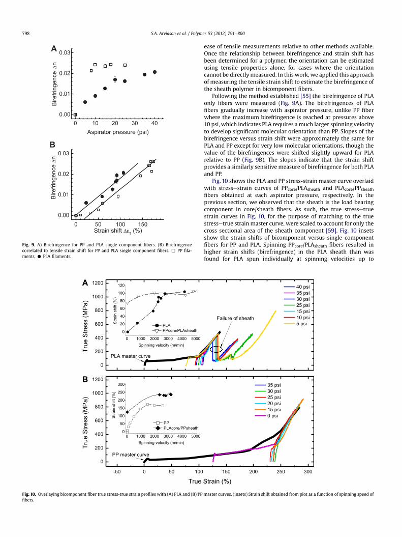
Following the method established [55] the birefringence of PLAonly fibers were measured (Fig. 9A). The birefringences of PLAfibers gradually increase with aspirator pressure, unlike PP fiberwhere the maximum birefringence is reached at pressures above10 psi, which indicates PLA requires amuch larger spinning velocityto develop significant molecular orientation than PP. Slopes of thebirefringence versus strain shift were approximately the same forPLA and PP except for very low molecular orientations, though thevalue of the birefringences were shifted slightly upward for PLArelative to PP (Fig. 9B). The slopes indicate that the strain shiftprovides a similarly sensitive measure of birefringence for both PLAand PP.
Fig. 10 shows the PLA and PP stress-strain master curve overlaidwith stressestrain curves of PPcore/PLAsheath and PLAcore/PPsheathfibers obtained at each aspirator pressure, respectively. In theprevious section, we observed that the sheath is the load bearingcomponent in core/sheath fibers. As such, the true stressetruestrain curves in Fig. 10, for the purpose of matching to the truestressetrue strain master curve, were scaled to account for only thecross sectional area of the sheath component [59]. Fig. 10 insetsshow the strain shifts of bicomponent versus single componentfibers for PP and PLA. Spinning PPcore/PLAsheath fibers resulted inhigher strain shifts (birefringence) in the PLA sheath than wasfound for PLA spun individually at spinning velocities up to
150 200 250 300
40 psi35 psi30 psi25 psi15 psi10 psi5 psi
Failure of sheath
Strain (%)
35 psi30 psi25 psi20 psi15 psi0 psi
master curves. (insets) Strain shift obtained from plot as a function of spinning speed of
0 1000 2000 3000 4000 5000
0.0
0.2
0.4
0.6
0.8
1.0 PLA only PPcore/PLAsheath
f a
Spinning velocity (m/min)
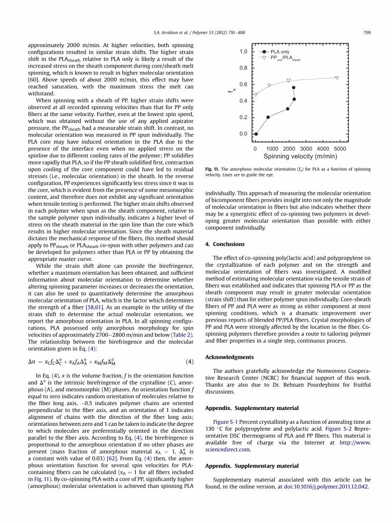
Fig. 11. The amorphous molecular orientation (fa) for PLA as a function of spinningvelocity. Lines are to guide the eye.
S.A. Arvidson et al. / Polymer 53 (2012) 791e800 799
approximately 2000 m/min. At higher velocities, both spinningconfigurations resulted in similar strain shifts. The higher strainshift in the PLAsheath relative to PLA only is likely a result of theincreased stress on the sheath component during core/sheath meltspinning, which is known to result in higher molecular orientation[60]. Above speeds of about 2000 m/min, this effect may havereached saturation, with the maximum stress the melt canwithstand.
When spinning with a sheath of PP, higher strain shifts wereobserved at all recorded spinning velocities than that for PP onlyfibers at the same velocity. Further, even at the lowest spin speed,which was obtained without the use of any applied aspiratorpressure, the PPsheath had a measurable strain shift. In contrast, nomolecular orientation was measured in PP spun individually. ThePLA core may have induced orientation in the PLA due to thepresence of the interface even when no applied stress on thespinline due to different cooling rates of the polymer; PP solidifiesmore rapidly that PLA, so if the PP sheath solidified first, contractionupon cooling of the core component could have led to residualstresses (i.e., molecular orientation) in the sheath. In the reverseconfiguration, PP experiences significantly less stress since it was inthe core, which is evident from the presence of somemesomorphiccontent, and therefore does not exhibit any significant orientationwhen tensile testing is performed. The higher strain shifts observedin each polymer when spun as the sheath component, relative tothe sample polymer spun individually, indicates a higher level ofstress on the sheath material in the spin line than the core whichresults in higher molecular orientation. Since the sheath materialdictates the mechanical response of the fibers, this method shouldapply to PPsheath or PLAsheath co-spun with other polymers and canbe developed for polymers other than PLA or PP by obtaining theappropriate master curve.
While the strain shift alone can provide the birefringence,whether a maximum orientation has been obtained, and sufficientinformation about molecular orientation to determine whetheraltering spinning parameter increases or decreases the orientation,it can also be used to quantitatively determine the amorphousmolecular orientation of PLA, which is the factor which determinesthe strength of a fiber [58,61]. As an example in the utility of thestrain shift to determine the actual molecular orientation, wereport the amorphous orientation in PLA. In all spinning configu-rations, PLA possessed only amorphous morphology for spinvelocities of approximately 2700e2800m/min and below (Table 2).The relationship between the birefringence and the molecularorientation given in Eq. (4):
Dn ¼ xCfCDoC þ xAfAD
oA þ xMfMDo
M (4)
In Eq. (4), x is the volume fraction, f is the orientation functionand Do is the intrinsic birefringence of the crystalline (C), amor-phous (A), and mesomorphic (M) phases. An orientation function fequal to zero indicates random orientation of molecules relative tothe fiber long axis, �0.5 indicates polymer chains are orientedperpendicular to the fiber axis, and an orientation of 1 indicatesalignment of chains with the direction of the fiber long axis;orientations between zero and 1 can be taken to indicate the degreeto which molecules are preferentially oriented in the directionparallel to the fiber axis. According to Eq. (4), the birefringence isproportional to the amorphous orientation if no other phases arepresent (mass fraction of amorphous material xA ¼ 1, Do
A isa constant with value of 0.03) [62]. From Eq. (4) then, the amor-phous orientation function for several spin velocities for PLA-containing fibers can be calculated (xA ¼ 1 for all fibers includedin Fig. 11). By co-spinning PLAwith a core of PP, significantly higher(amorphous) molecular orientation is achieved than spinning PLA
individually. This approach of measuring the molecular orientationof bicomponent fibers provides insight into not only the magnitudeof molecular orientation in fibers but also indicates whether theremay be a synergistic effect of co-spinning two polymers in devel-oping greater molecular orientation than possible with eithercomponent individually.
4. Conclusions
The effect of co-spinning poly(lactic acid) and polypropylene onthe crystallization of each polymer and on the strength andmolecular orientation of fibers was investigated. A modifiedmethod of estimating molecular orientation via the tensile strain offibers was established and indicates that spinning PLA or PP as thesheath component may result in greater molecular orientation(strain shift) than for either polymer spun individually. Core-sheathfibers of PP and PLA were as strong as either component at mostspinning conditions, which is a dramatic improvement overprevious reports of blended PP/PLA fibers. Crystal morphologies ofPP and PLA were strongly affected by the location in the fiber. Co-spinning polymers therefore provides a route to tailoring polymerand fiber properties in a single step, continuous process.
Acknowledgments
The authors gratefully acknowledge the Nonwovens Coopera-tive Research Center (NCRC) for financial support of this work.Thanks are also due to Dr. Behnam Pourdeyhimi for fruitfuldiscussions.
Appendix. Supplementary material
Figure S-1 Percent crystallinity as a function of annealing time at130 �C for polypropylene and polylactic acid. Figure S-2 Repre-sentative DSC thermograms of PLA and PP fibers. This material isavailable free of charge via the Internet at http://www.sciencedirect.com.
Appendix. Supplementary material
Supplementary material associated with this article can befound, in the online version, at doi:10.1016/j.polymer.2011.12.042.
S.A. Arvidson et al. / Polymer 53 (2012) 791e800800
References
[1] Hollaway LC. Constr Build Mater 2010;24(12):2419e45.[2] Bouza R, Marco C, Naffakh M, Barral L, Ellis G. Composites Part A 2011;42:
935e49.[3] Raftery G, Harte A. Composites Part B 2011;42(4):724e35.[4] Windt M, Dietrich M, Lehnen R. Holzforschung 2011;65(2):199e207.[5] Sung J, Huh J, Choi J-H, Kang SJ, Choi YS, Lee GT, et al. Adv Funct Mater 2010;
20:4305e13.[6] Yuan J-K, Yao S-H, Dang Z-M, Sylvestre A, Genestoux M, Bai J. J Phys Chem C
2011;115:5515e21.[7] Zhan M, Wool RP, Xiao JQ. Composites Part A 2011;42:229e33.[8] Filip D, Macocinschi D, Vlad S. Composites Part B 2011;42(6):1474e9.[9] Kanungo I, Chellappa N, Fathima NN, Rao JR. Int J Biol Macromol 2011;49(3):
289e96.[10] Fuentes CA, Tran LQN, Dupont-Gillain C, Vanderlinden W, De Feyter S, Van
Vuurea AW, et al. Colloids Surf A 2011;380:89e99.[11] Moriana R, Vilaplana F, Karlsson S, Ribes-Greus A. Composites Part A 2011;42:
30e40.[12] Hu R, Lim J-K. J Compos Mater 2011;41(13):1655e69.[13] Plackett D, Andersen TL, Pedersen WB, Nielsen L. Compos Sci Technol 2003;
63:1287e96.[14] Huda MS, Drzal LT, Mohanty AK, Misra M. Compos Sci Technol 2008;68:
424e32.[15] Riaz U, Ashraf SM, Sharma HO. Polym Degrad Stab 2011;96(1):33e42.[16] Mohamed AA, Finkenstadt VL, Palmquist DE. J Appl Polym Sci 2008;107:
898e908.[17] Shibata M, Ozawa K, Teramoto N, Yosomiya R, Takeishi H. Macromol Mater
Eng 2003;288(1):35e43.[18] Cargill, Inc, Kimura K. Fujitsu Sci Tech J 2005;41(2):173e80 [accessed
06/30/2010], http://www.cargill.com/corporate-responsibility/environmental-innovation/pioneering-new-business/corn-plastic/index.jsp.
[19] Mutsuga M, Kawamura Y, Tanamoto K. Food Addit Contam A 2008;25(10):1283e90.
[20] Murariu M, Ferreira AD, Alexandre M, Dubois P. Polym for Advan Technol2008;19(6):636e46.
[21] Nyambo C, Mohanty AK, Manjusri M. Biomacromolecules 2010;11(6):1654e60.
[22] Agarwal M, Koelling KW, Chalmers JJ. Biotechnol Progr 1998;14(3):517e26.[23] Holm VK, Ndoni S, Risbo J. J Food Sci 2006;71(2):E40e4.[24] Mohd-Adnan AF, Nishida H, Shirai Y. Polym Degrad Stabil 2008;93(6):1053e8.[25] Yeo SY, Jeong SH. Polym Int 2003;52(7):1053e7.[26] Badrossamay MR, Sun G. J Biomed Mater Res B 2009;89B(1):93e101.[27] Dastjerdi R, Mojtahedi MRM, Shoshtari AM, Khosroshahi A. J Text 2010;
101(3):204e13.[28] Tao D, Feng QA, Gao DW, Pan LA, Wei QF, Wang DJ. J Appl Polym Sci 2010;
117(3):1624e30.
[29] Ren WT, Cheng CZ, Wang RM, Li X. J Appl Polym Sci 2010;116(4):2480e6.[30] Matos JP, Sansiviero MTC, Lago RM. J Appl Polym Sci 2010;115(6):3586e91.[31] Bahners T, Hassler R, Gao SL, Mader E, Wego A, Schollmeyer E. Appl Surf Sci
2009;255(22):9139e45.[32] Zhu SQ, Hirt DE. Text Res J 2009;79(6):534e47.[33] Spagnola JC, Gong B, Arvidson SA, Jur JS, Khan SA, Parsons GN. J Mater Chem
2010;20(20):4213e22.[34] Wei QF, Shao DF, Deng BY, Xu Y. J Appl Polym Sci 2009;114(3):1813e9.[35] Hegde RR, Bhat GS. J Appl Polym Sci 2010;115(2):1062e72.[36] Hua XQ, Zhang TZ, Ren J, Zhang ZG, Ji ZL, Jiang XL, et al. Colloids Surf A 2010;
369(1e3):128e35.[37] Vaikhanski L, Lesko JJ, Nutt SR. Compos Sci Technol 2003;63(10):1403e10.[38] Cho HH, Kim KH, Kang YA, Ito H, Kikutani T. J Appl Polym Sci 2000;77(10):
2254e66.[39] Chester S. PLA Spunbond e gateway to the future. In insight 2008 Interna-
tional Conference, 2008.[40] Reddy N, Nama D, Yang YQ. Polym Degrad Stabil 2008;93(1):233e41.[41] Wojciechowska E, Fabia J, Slusarczyk C, Gawlowski A, Wysocki M, Graczyk T.
Fibres Text East Eur 2005;13(5):126e8.[42] NatureWorks, LLC. http://www.natureworksllc.com/ [accessed 06/30/10].[43] Tao GL, Gong AJ, Lu JJ, Sue HJ, Bergbreiter DE. Macromolecules 2001;34(22):
7672e9.[44] Dorgan J, Janzen J, Clayton M. J Rheol 2005;49(3):607e19.[45] Wong KC, Haslauer CM, Anantharamaiah N, Pourdeyhimi B, Batchelor AD,
Griffis DP. Microsc Microanal 2010;16(3):282e90.[46] Wang X, Gong R. Macromol Mater Eng 2006;291:499e509.[47] Lafrance C, Prudhomme R. Polymer 1994;35:3927e35.[48] Yan R, Li W, Li G, Jiang B. Macromol Sci Phys 1993;B32:15e31.[49] Sarasua JR, Rodríguez N, Arraiza A, Meaurio E. Macromolecules 2005;38(20):
8362e71.[50] Lengyel M, Mathe K, Bodor G. Acta Chim Hung 1977;94(4):309e20.[51] Makradi A, Cox CL, Ahzi S, Belouettar S. J Appl Polym Sci 2006;100(3):
2259e66.[52] McHugh AJ, Doufas AK. Compos Part A-Appl S 2001;32(8):1059e66.[53] Nadella HP, Henson HM, Spruiell JE, White JL. J Appl Polym Sci 1977;21(11):
3003e22.[54] Li LB, de Jeu WH. Advances in polymer science: interphases and mesophases
in polymer crystallization II 2005 181/2005, pp. 75e120.[55] Arvidson SA, Khan SA, Gorga RE. Macromolecules 2010;43(6):2916e24.[56] Houis S, Schmid M, Lubben J. J Appl Polym Sci 2007;106:1757e67.[57] Sun B, Duan B, Yuan X. J Appl Polym Sci 2006;102:39e45.[58] Shi XQ, Ito H, Kikutani H. Polymer 2006;47(2):611e6.[59] Zilberman M, Kraitzer A. J Biomed Res Part A 2008;84A(2):313e23.[60] Park C-W. AIChE J 1990;36:10.[61] Samuels RJ. Structured polymer properties: the Identification, Interpretation,
and application of crystalline polymer structure. New York: Wiley; 1974.[62] Ou X, Cakmak M. Polymer 2008;49(24):5344e52.