stuck pipe prevention in high angle wells
DESCRIPTION
Precautions to take to avoid stuck pipe in high angle wells due to mud loading in the wellbore. This is hole cleaning issue related.TRANSCRIPT
Stuck Pipe in High Angle 12¼”HoleCause & Prevention
Peter McNaughton
Baroid Technical Manager - Kuwait
© 2010 Halliburton. All Rights Reserved.
Agenda
1. Introduction & Reason for the Presentation
2. Causes & Prevention of Stuck Pipe in High Angle 12¼” hole
a. Mud weight
b. Hole cleaning
c. Monitoring of hole cleaning indicators
d. Tripping, circulating & connection practices
3. Kuwait Example, hole cleaning modeling

© 2010 Halliburton. All Rights Reserved.
Introduction
Reason for this presentation:
� Many examples of stuck pipe / tight hole in 12¼” hole build sections
� Why? Investigate possible causes.
� Improve planning & execution of future horizontal wells, e.g. Zubair horizontals & Mauddud/Burgan multilaterals
� Prevent stuck pipe = save drilling days & increase production
� Introduce the “Two Hat” policy, i.e. different thinking & procedures for: � Low angle hole
� High angle hole

© 2010 Halliburton. All Rights Reserved.
How To Drill Big Diameter High Angle Hole?
� Understand, model, plan!
� The principles are the same for your 12¼” build sections
High angle 17½” & 12¼” intervals
9.5 - 12 ppg OBM

© 2010 Halliburton. All Rights Reserved.
Causes of Stuck Pipe in Deviated 12¼” Hole
1. Geology: shale swelling/inhibition & weak formations
2. Borehole instability due to inadequate mud weight
3. Poor hole cleaning practices

© 2010 Halliburton. All Rights Reserved.
Understand the Problem -Where Do All the Cavings Come From?
What causes all the cavings in the 12¼” build section?
� Inadequate chemical inhibition?
� Insufficient hydrostatic head after downhole losses?
� Roof collapse?
� Directional tectonic stress?
� Mechanical disturbance of weak formations?
� Borehole flexing due to surge/swab pressures?
� Pore pressure penetration?
� Time?
� Combination of these?

© 2010 Halliburton. All Rights Reserved.
Reactive Shale Inhibition
� Do we have reactive shales in the 12¼” build section?
� Slight to moderate reactive shales exist in 4 formations in the 12¼” build section
Shale composition typically doesn’t change much over wide areas, so Burgan data is
relevant for North Kuwait
Relative Clay %
Mixed Layer - Illite + Smectite Illite + Mica Total Reactive Clays, %
Field &
Location
Ahmadi
NE
Magwa
NW
Burgan
S
Ahmadi
NE
Magwa
NW
Burgan
S
Ahmadi
NE
Magwa
NW
Burgan
S
Ahmadi Fm. 14 34 48
Wara Fm. 9 8 4 11 14 7 20 22 11
Mauddud Fm. - 0 - - 73 - - 73 -
Burgan Fm. 16 10 8 18 28 11 34 38 19
Reactive Shale Data – Greater Burgan Area

© 2010 Halliburton. All Rights Reserved.
Inhibit Shale Swelling – Mud Formulation
Is reactive clay swelling a problem in the 12¼” section?
� Answer: Do MBT values increase rapidly?
Is rheology difficult to control due to clay buildup?
How to control reactive clay swelling?
� WBM or OBM to control the shales?
� Balanced salinity OBM is best for inhibition, but lost circulation
in the Shuaiba is the risk
� Experience has shown that a KCl-Polymer system with 3 – 6% KCl is appropriate for the 12¼” build section
� Glycols, asphaltics etc. are also useful in WBM to:
� Reduce pore pressure penetration
� Increase open hole exposure time (OHET)

© 2010 Halliburton. All Rights Reserved.
What is Pore Pressure Penetration?
Overburden Stress (S) = Matrix Stress (σ) + Pore Pressure (P)
� Filtrate enters shale thru pores (~1µ diameter), bedding planes &
micro-fractures
� This allows fluid pressure to slowly increase in the shale
� As pore pressure increases, rock strength decreases
� This is the main reason that shale destabilizes with time
� Is shale failure in Kuwait time-dependent?
� If “yes”, add plugging agents to increase shale capillary entry
pressure, or use balanced-salinity OBM
© 2010 Halliburton. All Rights Reserved.
Inadequate Mud Weight
Is the mud weight high enough to control:
� Oriented borehole breakout (directional tectonic stress)
� Collapse of unsupported roof
� Excessive pore pressure in shales
� Swabbing pressure on connections or trips
� Loss of hydrostatic head when downhole losses occur

© 2010 Halliburton. All Rights Reserved.
How to Calculate Correct Mud Density
Correct mud density depends on what?
� Maximum expected pore pressure +
� Safety factor (“trip margin”),
e.g. 0.5 ppg +
� Borehole collapse factor for deviated hole,
e.g. 0.5 ppg / 30°of hole angle, +
� Directional tectonic stress factor,
e.g. 0 – 2.5 ppg, +
� Formation strength factor
e.g. 0 – 1 ppg
Oriented Borehole
Breakout in direction
of Minimum
Horizontal Stress
(σHmin)
σHminσHmax

© 2010 Halliburton. All Rights Reserved.
Trip Margin & Rock Strength
Trip Margin
� Extra hydrostatic pressure is required to allow some swabbing during a trip out of the hole without inducing a well influx (kick)
� This safety factor allows a safe trip out of the hole, so is called “Trip margin”
� “Rule of thumb” value for trip margin is 0.5 ppg
� KOC’s stated trip margin for drilling fluids = 250 psi above the formation pressure
� At 10,000ft TVD, 250 psi overbalance = 0.5 ppg
Rock Strength
� Extra mud weight is often required in high angle hole to stabilize weak rock, e.g. coal, fractured shale & loose sand

© 2010 Halliburton. All Rights Reserved.
Mud Weight in Deviated Hole
Hole angle:
� 0 - 30
� 30 - 60
� 60 - 90
Mud weight increase:
� 0 – 0.5 ppg
� 0.5 – 1.0 ppg
� 1.0 – 1.5 ppg
Rule of Thumb - Hole angle versus mud weight
Higher mud weight is required to stabilize unsupported rock (the roof) in high angle hole

© 2010 Halliburton. All Rights Reserved.
Oriented Borehole Breakout� Green log plot shows significant
hole enlargement in one direction, but not in another
� Log for the three caliper arms do not overlap, indicating oval hole shape
� Circle shapes show oval hole shape in an approximate NNW direction. This is the direction of
minimum horizontal stress (σHmin)
� This agrees with the known tectonic stress regime in Kuwait, where the direction of maximum
tectonic stress (σHmax) is at an
azimuth of 010°– 045°.
� Oriented breakout is greatest in the shale (high Gamma Ray values), which is the most stressed lithology.
AH-178 - 12¼” Deviated Hole
4100 – 4300 ft

© 2010 Halliburton. All Rights Reserved.
Casing Depth
Is the casing depth optimized to allow the correct MW to be used?
� Three big problems in the 12¼” build section:
� Increase MW to control shale pore pressure
� Increase MW to manage hole angle & tectonic stress
� Reduce MW due to lost circulation in the Shuaiba
� Experience in previous 12-1/4” sections building
to high angle shows many hole problems, with
stuck pipe common
� Very difficult to reconcile two opposing mud
weight constraints
� Can we change the casing design?
AD-61Lower well section

© 2010 Halliburton. All Rights Reserved.
Hole Cleaning Indicators
Warning signs: Comments
- Hole angle > 30°
- AV < 120 ft/min
- Low pipe rpm
- Mud wt < 10 ppg
If one or two of these factors are present, then poor hole cleaning is likely.
If more than two of these factors are present, then poor hole cleaning is certain to occur.
� Do we have a hole cleaning problem?
� In Zubair horizontals, two or three of these factors will be present in the 12¼” build section
© 2010 Halliburton. All Rights Reserved.
Inadequate Hole Cleaning
� Cuttings bed buildup on the low side of the hole
� Inadequate annular velocity
� Drill pipe size versus hole diameter
� Insufficient drill string rpm
� Sliding versus rotating
� Insufficient hole cleaning cycles
� Inappropriate mud rheology & rheology specifications
� Incorrect sweeps & sweeps wrongly applied
� Hole enlargement
� Cavings
� Operator & Contractor lack of awareness
© 2010 Halliburton. All Rights Reserved.
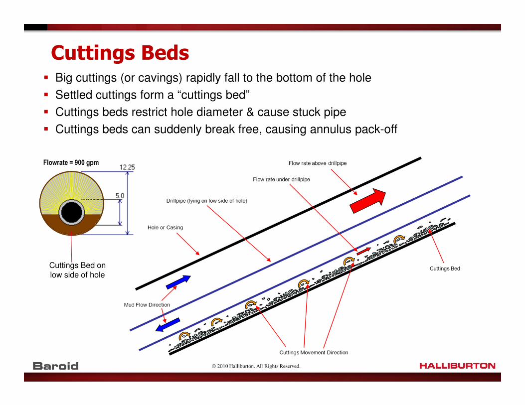
Cuttings Beds� Big cuttings (or cavings) rapidly fall to the bottom of the hole
� Settled cuttings form a “cuttings bed”
� Cuttings beds restrict hole diameter & cause stuck pipe
� Cuttings beds can suddenly break free, causing annulus pack-off
Flowrate = 900 gpm
Cuttings Bed on low side of hole

© 2010 Halliburton. All Rights Reserved.
High Angle Hole Cleaning: 7 Primary Factors
Hole cleaning factors for deviation > 40°(in order of importance)
1. Annular velocity. Minimum 120 ft/min. AV depends on:� Annulus diameter. Big hole diameter = bad; Small pipe diameter = bad.
� Pump output . More = good
� Hole enlargement = Bad
2. Cuttings (or cavings) size Cavings = bad
� Big cuttings & cavings cannot be cleaned from a high angle hole
3. Drill string RPM. High rpm = good. Sliding = bad.
� High rpm kicks cuttings from the low side of the hole up into the main flow path
4. Hole angle. More = bad
� Cuttings beds form on the low side of the hole at angles > 40°
5. Mud density More = good (increased buoyancy)
� Hole cleaning problems do not occur at high mud density
6. Hole rheology Not too thick & not too thin
� YP & Funnel Vis are useless values at hole angles > 40°
7. Hole cleaning cycles How many bottoms up is needed to clean the hole?

© 2010 Halliburton. All Rights Reserved.
Annular Velocity Target > 120 ft/min
How can we achieve this target through the entire 12¼”
build section:
� Use larger diameter drillpipe → smaller annular diameter in the
high angle section
� Minimize hole enlargement, e.g.
� Prevent borehole breakout by using the correct mud weight
� Don’t back-ream
� Minimize ultra-fine low gravity solids content, e.g.
� Improve hole cleaning to remove cuttings quickly
� Use efficient fine shaker screens, mud cleaners & centrifuges to remove solids on the first pass
� Maintain a tight LGS specification in the mud

© 2010 Halliburton. All Rights Reserved.
Minimum Flow Rate for AV = 120 ft/min
Hole Size Annular
Velocity
(ft/min)
Target Flow Rate, Q(gal/min)
5” drillpipe 5½” drillpipe 6⅝” drillpipe
16” 120 1130 1104 1038
12¼” 120 612 586 519
8½” 120 231 206 -
Gauge Hole Washed Out Hole

© 2010 Halliburton. All Rights Reserved.
Cuttings Size
� How big is a cutting from a 12¼” PDC bit (16 mm cutters)?
� The mud must be able to remove this cutting from the hole
© 2010 Halliburton. All Rights Reserved.
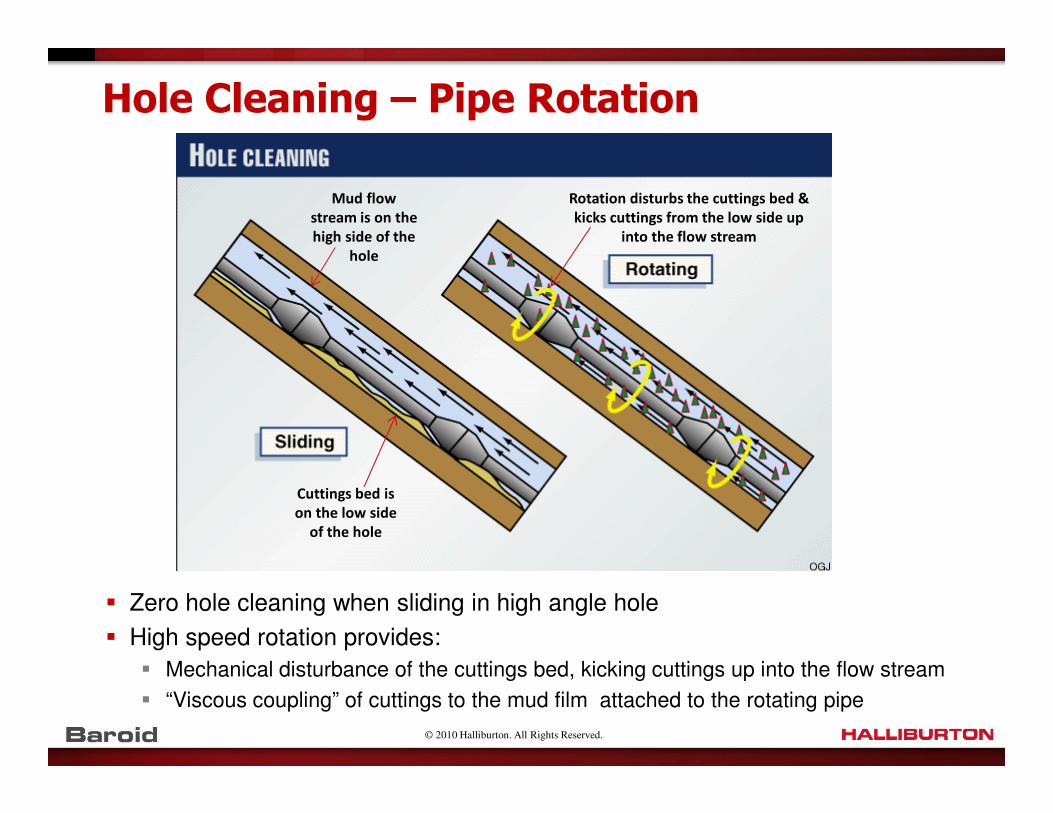
Hole Cleaning – Pipe Rotation
� Zero hole cleaning when sliding in high angle hole
� High speed rotation provides:
� Mechanical disturbance of the cuttings bed, kicking cuttings up into the flow stream
� “Viscous coupling” of cuttings to the mud film attached to the rotating pipe
Cuttings bed is
on the low side
of the hole
Mud flow
stream is on the
high side of the
hole
Rotation disturbs the cuttings bed &
kicks cuttings from the low side up
into the flow stream

© 2010 Halliburton. All Rights Reserved.
Hole Cleaning Monitoring
How do we measure hole cleaning efficiency?
� On-bottom & off-bottom torque (do we measure & graph?)
� Pick-up & slack-off weight on connections (drag)
� Quantity, size & shape of cuttings at the shakers
� Increased cuttings size & quantity when a sweep returns
� Tight hole on trips
� Pump pressure spikes – indicates annulus pack-off
� Use PWD tool to monitor ECD caused by cuttings load
� Compare ROP against cuttings at the shaker
� Waves of cuttings at the shakers
Good hole cleaning –
angular shapePoor hole cleaning –
rounded shapeGood hole cleaning, but
shale is caving
Good hole cleaning, but
mud weight is too low

© 2010 Halliburton. All Rights Reserved.
Torque & Drag Plot - 12¼” Deviated Hole
Diverging pick-up & slack-off weights indicates a cuttings bed build-up
Pick-up & slack-off weights returned to normal after a hole cleaning cycle

© 2010 Halliburton. All Rights Reserved.
Pill/Sweep Report
Date
2011
Hole
Size
(in)
Bit
Depth
(m MD)
Tangent
Angle
(º)
Pill
Volume
(bbl)
Pill
Weight
(ppg)Pill Composition &
Key Properties
Results, e.g. Before & After Values:
(% increase cuttings at shakers; cuttings/cavings
size & lithology; pick-up & slack-off weight; etc.)
6 Feb 17½ 1255 0 300 8.8
2.5 ppb CMC EHV + 20
ppb Bentonite. Vis = 90
sec/qt.
While POOH at section TD, spotted 300 hi-vis mud to
bottom. No drag or overpull while POOH.
10
Feb12¼ 1400 10 100 9.5
KCl/Polymer premix +
22 ppb CaCO3 (C) + 22
ppb CaCO3 (M) + 22
ppb CaCO3 (F) + 25 ppb
STEELSEAL + 5 ppb
BAROFIBRE + barite
On standby at start of 12¼” interval.
16
Feb12¼ 2419 37 50 12.1
Active mud with 0.25
ppb BAROLIFT
Pumped hole cleaning sweep before trip.
Cuttings volume increased by ~ 50% when sweep
returned. Some large cuttings/cavings with
rounded edges.
Slack-off wt reduced by 10%.
SWEEP & PILL REPORT FORMOperator: xxxx Well: xxxx
� Mud engineer to report hole cleaning sweeps
� Recommended to monitor hole cleaning effectiveness

© 2010 Halliburton. All Rights Reserved.
Hole Cleaning – Optimum Rheology
What is the optimum mud rheology in high angle hole?
� “Not too thin”� Thin mud cannot suspend big cuttings (or cavings)
� They rapidly fall to the bottom of the hole to form a “cuttings bed”
� “Not too thick”� Thick mud cannot penetrate the cuttings bed under the drill pipe
� Thick mud will travel up the high side of the hole
� “Just right”� Intermediate rheology is best
� Rule of thumb:6 rpm viscometer value ≈ 0.8 – 1.5 x hole diameter (inches)
� For big hole, use 1.2 – 1.5 x hole diameter
� For small hole, use 0.8 – 1.0 x hole diameter

© 2010 Halliburton. All Rights Reserved.
High Angle Hole – Rheology Specification
Best rheology specification for high angle hole?
� 6 rpm Viscometer Dial Reading� Closest measurement to the annulus flow rate past the drillpipe
� Closest measurement to the most difficult annulus section to clean
� Low Shear Rate Yield Point (LSR YP)� Calculates YP using 3 & 6 rpm viscometer values
� LSR YP = 2 x θ3 – θ6
� Represents the annulus flow rate past the drillpipe better than Bingham YP
� Sometimes inaccurate. Small differences in viscometer values can cause big
changes in LSR YP.
� Herschel-Bulkley Tau Zero (Yield Stress)� Intercept on Y-axis of viscometer dial reading versus viscometer speed
� “True Yield Point”
� Calculated by curve fit to actual mud viscosity profile
� Gives more accurate hydraulics calculations than Bingham or Power Law

© 2010 Halliburton. All Rights Reserved.
Fluid Viscosity Profile
� Which rheology model is most accurate for hydraulics calcs?
0
20
40
60
80
0 100 200 300 400 500 600
Shear Rate (rpm)
Vis
com
ete
r D
ial R
eadin
g
Measured Points
Herschel-Bulkley
Power Law
Bingham Plastic
600 rpm = 63
300 rpm = 38
200 rpm = 28
100 rpm = 18
6 rpm = 8
3 rpm = 7Herschel-Bulkleymodel closely fits actual fluid profile
Bingham YP
H-B Yield Stress (Tau zero)

© 2010 Halliburton. All Rights Reserved.
Fluid Viscosity Profile
120ft/min annular velocity in 12-1/4” hole
For 12 ¼” hole & 120 ft/min annulus velocity :
Annulus shear rate = 2.4 x AV / [Dh – Dp] = 40 sec-1
Equivalent viscometer rotor speed = annulus shear rate / 1.703 = 23 rpm
6 rpm viscometer reading is the best measure of the fluid viscosity in the open hole annulus where
hole cleaning is critical
© 2010 Halliburton. All Rights Reserved.
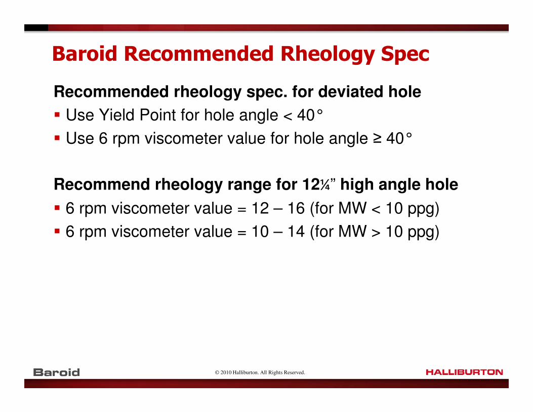
Baroid Recommended Rheology Spec
Recommended rheology spec. for deviated hole
� Use Yield Point for hole angle < 40°
� Use 6 rpm viscometer value for hole angle ≥ 40°
Recommend rheology range for 12¼” high angle hole
� 6 rpm viscometer value = 12 – 16 (for MW < 10 ppg)
� 6 rpm viscometer value = 10 – 14 (for MW > 10 ppg)

© 2010 Halliburton. All Rights Reserved.
Hole Cleaning Cycle
1. How many bottoms up (cycles) to clean the hole?
2. What is the Circulation Factor?
� These are minimum values
� Actual circulation time will be until the shakers clean up
Deviation Circulation Factor (= minimum circulation volume)
Hole Size 17½” & 16” 12¼” 8½”
Vertical (<10°) 1.5 x B/U 1.3 x B/U 1.3 x B/U
10 - 30° 1.7 x B/U 1.4 x B/U 1.4 x B/U
30 - 60° 2.5 x B/U 1.8 x B/U 1.6 x B/U
> 60° 3.0 x B/U 2.0 x B/U 1.7 x B/U

© 2010 Halliburton. All Rights Reserved.
High Angle Hole Cleaning – Secondary Factors
Hole Cleaning Sweeps
1. Good Sweeps:
� Best sweep materials are:
� Weighted sweeps Provide buoyancy. Best if 4 ppg > MW.
� Coarse fibres. Fibres form a mat; Sweep is removed by shakers
� Coarse Barite weighted sweep (Sweep-Wate) Sweep is removed by shakers
� Keep sweep rheology the same as mud rheology.
2. Bad Sweeps� Hi-vis sweeps are useless in high angle hole
� Sweep goes up the high side of the hole
� Cuttings bed remains on the low side of the hole
� Tandem sweeps cause more harm than good:
� Low-weight component may rise in the well & cause a kick
� Low-weight component can cause borehole wall to flex & weaken
� Hi-vis component is useless in high angle hole
� Tandem sweeps destabilize mud properties

© 2010 Halliburton. All Rights Reserved.
High Angle Hole Cleaning – Secondary Factors
Circulating Practices
� Circulate cuttings above the BHA before making a connection
� Circulate at drilling flow rate & rpm when reaming upwards
� Circulate at drilling flow rate & low rpm when reaming downwards (to avoid inadvertently kicking off into new hole)
� Circulate the correct number of bottoms-up cycles, based on:� Circulation factor
� Drillstring rpm
� Hole angle
� Possible hole enlargement
� Circulate until the shakers clean up
� Circulate sweeps all the way out (do not stop pumping)
� Do not have more than one sweep in the hole at the same time
� DO NOT BACKREAM unless it is the only way to get out of the hole

© 2010 Halliburton. All Rights Reserved.
High Angle Hole Cleaning – Secondary Factors
The trouble with back-reaming:
� Pipe is pulled into the roof of the hole when back-reaming
� Large cuttings are cut from the roof of the hole
� This causes several problems:� Hole diameter gets bigger, so annulus velocity reduces
� Extra large cuttings are generated that must be removed from the hole
� The extra large cuttings may block the annulus (annulus pack-off)
� Stuck pipe often occurs when back-reaming, usually after a pack-off occurs

© 2010 Halliburton. All Rights Reserved.
High Angle Hole Cleaning – Secondary Factors
Tripping Practices
� A cuttings bed will always be present in 12¼” hole at angles > 40°
� You will drag cuttings up the hole when you trip (snowplow effect)
� If tight hole occurs on the trip out:� DO NOT BACKREAM
� RIH one or two stands
� Perform a hole cleaning cycle (high rpm & flow rate)
� POH again
� If the tight spot is not there, then it was caused by a cuttings bed
© 2010 Halliburton. All Rights Reserved.
Drillstring Failure & Corrosion Monitoring
� High angle big diameter hole puts maximum stress on the drill string
� Weakness caused by corrosion will cause the drillstring to fail
� Stuck pipe in high angle hole is expensive (expensive tools are lost)
� Stuck pipe in high angle hole is difficult to fish
To prevent drillstring failure in high angle drilling:
� Use corrosion monitoring & treatment to reduce the risk of failure
� Blueprint, register & inspect all pipe, crossovers & subs run in the hole
� Use lubricants (including OBM lubricants) to reduce torque & drag
� Minimize cumulative dogleg in the upper hole to reduce torque & drag

© 2010 Halliburton. All Rights Reserved.
Case History – North Kuwait
AD-61 Abdaly Field, North Kuwait
� Horizontal Zubair producer
� 12¼” interval with 5” DP
� Build hole angle to 67°
� Water base mud (KCl-Polymer- Glycol)
� Drill with rotary steerable system (RSS) or mud motor
� Twisted off while reaming tight hole at 10,750 ft.
Unable to fish
� Inadequate hole cleaning partly to blame
Similar occurrences in AD-57, including stuck pipe, annulus
pack-off & tight hole requiring backreaming

© 2010 Halliburton. All Rights Reserved.
Measured Depth
CuttingsBed Height
Flowrate = 900 gpm
Hole Cleaning in High Angle Wells
� Baroid’s DFG Hole Cleaning Modeling
� Calculate cuttings loading in annulus
� Identifies poor hole cleaning
� Calculates ECD of mud system & sweeps
� Optimize rheology & other hole cleaning factors
� Can be used in real time with PWD tool
Hole Cleaning – Rules of Thumb
� < 10% cuttings load in any hole section
� < 3% total cuttings load in annulus

© 2010 Halliburton. All Rights Reserved.
Fair Hole Cleaning – Actual Parameters
AD-61, 12¼” Hole at 10,663 ft, Drill w/RSS, Cutting size = 0.3”
MW = 9.0
PV = 20
YP = 25
6 rpm = 10
Tau0 = 7.0
LSR YP = 4
Q = 500 gpm
Rpm = 100
Angle = 610.3 inch cutting.Cuttings bed present.Hole cleaning fair.Max cuttings conc’n < 10% in the high angle section
Hole cleaning OK.Avg. cuttings conc’n < 3.0%

© 2010 Halliburton. All Rights Reserved.
Poor Hole Cleaning – Actual Parameters
AD-61, 12¼” Hole at 10,663 ft, Drill w/RSS, Cutting size = 0.5”
MW = 9.0
PV = 20
YP = 25
6 rpm = 10
Tau0 = 7.0
LSR YP = 4
Q = 500 gpm
Rpm = 100
Angle = 61½ inch cutting.Large cuttings bed.Hole cleaning poor.Max cuttings conc’n > 10% in the high angle section
Hole cleaning poor.Avg. cuttings conc’n > 3.0%
ECD with cuttings very high

© 2010 Halliburton. All Rights Reserved.
Very Poor Hole Cleaning – Actual Parameters
AD-61, 12¼” Hole at 10,663 ft, Drill w/RSS, Cutting size = 0.7”
MW = 9.0
PV = 20
YP = 25
6 rpm = 10
Tau0 = 7.0
LSR YP = 4
Q = 500 gpm
Rpm = 100
Angle = 61

© 2010 Halliburton. All Rights Reserved.
Good Hole Cleaning – Optimum Parameters
AD-61, 12¼” Hole at 10,663 ft, Drill w/RSS, Cutting size = 0.3”
MW = 9.0
PV = 20
YP = 25
6 rpm = 10
Tau0 = 7.0
LSR YP = 4
Q = 600 gpm
Rpm = 100
Angle = 61

© 2010 Halliburton. All Rights Reserved.
Poor Hole Cleaning – Larger Cuttings
AD-61, 12¼” Hole at 10,663 ft, Drill w/RSS, 100 rpm, Cutting size = 0.5”
MW = 9.0
PV = 20
YP = 25
6 rpm = 10
Tau0 = 7.0
LSR YP = 4
Q = 600 gpm
Rpm = 100
Angle = 61

© 2010 Halliburton. All Rights Reserved.
Summary
� Understand, model & plan for high angle big hole!
� Two hats: Low angle & high angle hole are completely different
� Understand:
� Geology → correct mud type & inhibition
� Pressures & forces → correct mud weight
� Hole cleaning issues → optimize practices
→ optimize or improve equipment
→ optimize rheology
� For interest, compare our findings with SPE 151953, “Planning
& Well Design for KOC’s first North Kuwait Jurassic Well
(SA297) – Case History”, 2012

© 2010 Halliburton. All Rights Reserved.
How Did We Drill This Well w/o Stuck Pipe?
Understand, model, plan!
� Borehole stability analysis
� Extensive hole cleaning & ECD modeling
using DFG
� Rigsite torque & drag monitoring
� Optimized rheology
� Circulate before trips until the hole is clean
� High weight sweeps (fibres not allowed)
� OBM lubricant
� No wiper trips
� No backreaming, except before running
casing
Equipment
� 4 x 2000HP mud pumps, with 7500
psi fluid ends
� 7500 psi standpipe
� 1200 gpm in 17-1/2” hole
� 800 -900 gpm in 12-1/4” hole
� PWD tool
� 5 Derrick 4-panel 514 shakers
� 2 mud cleaners
� 3 centrifuges
� RSS mandatory, rotating at 150 –
180 rpm
� 5-7/8” drillpipe (later 6-5/8” DP)
� Non-rotating stabilizers
� Roller centralizers to run casing
� 9000 bbl mud system
� Mud plant at the rig
� Cuttings slurrification unit, injection
pump & injection well at the rig