studies in software-defined radio system implementation
TRANSCRIPT
Running head: SOFTWARE-DEFINED RADIOS 1
Studies in Software-Defined Radio System Implementation
Harold A. Haldren, III
A Senior Thesis submitted in partial fulfillment
of the requirements for graduation
in the Honors Program
Liberty University
Spring 2014
SOFTWARE-DEFINED RADIOS 2
Acceptance of Senior Honors Thesis
This Senior Honors Thesis is accepted in partial
fulfillment of the requirements for graduation from the
Honors Program of Liberty University.
______________________________ Kyung Bae, Ph.D.
Thesis Chair
______________________________
Carl Pettiford, Ph.D.
Committee Member
______________________________ Monty Kester, Ed.D.
Committee Member
______________________________ Brenda Ayres, Ph.D.
Honors Director
______________________________
Date

SOFTWARE-DEFINED RADIOS 3
Abstract
Over the past decade, software-defined radios (SDRs) have an increasingly prevalent
aspect of wireless communication systems. Different than traditional hardware radios
which implement radio protocols using static electrical circuit, SDRs implement
significant aspects of physical radio protocol using software programs running on a host
processor. Because they use software to implement most of the radio functionality, SDRs
are much more easily modified, edited, and upgraded than their hardware-defined
counterparts. Consequently, researchers and developers have been developing previously
hardware-defined radio systems within software. Thus, communication standards can be
tested under different conditions or swapped out entirely by simply changing some code.
Additionally, developers hope to implement more advanced functionality with SDRs
such as cognitive radios that can sense the conditions of the environment and change
parameters or protocol accordingly. This paper will outline the major aspects of SDRs
including their explanation, advantages, and architecture.
As SDRs have become more commonplace, many companies and organizations
have developed hardware front-ends and software packages to help develop software
radios. The most prominent hardware front-ends to date have been the USRP hardware
boards. Additionally, many software packages exist for SDR development, including the
open source GNU Radio and OSSIE and the closed source Simulink and Labview SDR
packages. Using these development tools, researchers have developed many of the most
relevant radio standards. This paper will explain the major hardware and software
development tools for creating SDRs, and it will explain some of the most important
SDR projects that have been implemented to date.
SOFTWARE-DEFINED RADIOS 4
Studies in Software Defined Radio System Implementation
Introduction
Radios are essential parts of everyday human communications, whether people
realize it or not. When most people think of radios, they think of the AM/FM radios in
their cars, hand-held two-way radios, or CB radios. However, radios are much more
prevalent in society than most realize. For instance, the Wi-Fi adapters within a computer
or smart-device are radios and Bluetooth earpieces used to talk on the phone are radios.
In general, a radio is any device that transmits or receives information wirelessly through
the use of electromagnetic waves known as radio waves.
Classically, radios have been made from pieces of hardware designed for use in
one specific radio. These radios can be referred to as hardware-defined radios because the
radio is completely dependent on the hardware such as electrical circuits and electronic
devices. However, software-defined radios, developed in the past few years, are a new
type of radio in which the type of radio is determined by a piece of software. These
software-defined radios (SDRs) or software radios are a developing technology with
many advantages that make them attractive to researchers and radio developers alike.
Background on Software-Defined Radios
The Need for Software-Defined Radios
In the past few decades, the field of wireless communications has been
developing and advancing at a rapid pace. Nearly all new electronic devices implement
some sort of wireless communications, be it in the form of Wi-Fi, Bluetooth, or cellular
technologies like CDMA or LTE. Each of these different radio systems has its own

SOFTWARE-DEFINED RADIOS 5
specific protocols. Consequently, these different radio systems had to be implemented
using hardware configurations.
Hardware radios use physical components which are not easily modified.
Consequently, this static nature gives hardware radios several limitations. First, needing
different hardware setups for each radio technology can use significant amounts of space,
especially if a particular setup needs several different radio technologies. Second,
implementing separate hardware protocols becomes expensive to systems needing to use
many different radio standards (Tribble, 2008). Cellular phone technology provides a key
example of this phenomenon. In cellular phone technology, entire nations and regions
have attempted to standardize the radio protocol; however, cell phones still need to
support old standards still in use and alternate standards in different regions so a single
phone can operate in many locations. Current hardware limitations cause cell phones to
have separate physical systems for each communication standard which increases both
the size and cost of cell phones. Third, hardware radios are not easily updated when new
technology is developed (Tribble). Radio technology and protocols are constantly
evolving to become faster and more advanced. Thus, a protocol used today could be
obsolete in just a few years. Under hardware-based radio schemes, systems would be
unusable whenever a new protocol is developed. Because of the limitations inherent in
static hardware radio systems, a different kind of radio system has been developed within
the past few years.
To solve the hardware problem, engineers decided to implement parts of the radio
using software rather than hardware. Using software rather than hardware to implement
some stages of a radio system enables a radio to be more easily configured, modified, and

SOFTWARE-DEFINED RADIOS 6
developed for multiple systems (Tribble, 2008). This new form of radio implementation
came to be known as software defined radio (SDR) or software radio. The goal of SDRs
is to implement fully functional radios in one system that previously needed multiple
systems.
The migration from hardware-defined radios to software-defined radios
corresponds with the move from analog radio systems to digital radio system. In the past,
the rise of microprocessors enabled communications engineers to develop a new way to
transmit information from one place to another. These digital communication systems
provided some key benefits over the existing analog communication systems. Despite the
advantages, however, both analog and digital communication systems still exist today.
Analog systems are still useful for some applications and digital systems will never be
able to completely replace analog systems. Similarly, the advantages of software radios
may allow them to overtake hardware radios in many situations throughout the coming
years; however, the simplicity and dependability of hardware radios will ensure these
radios continue to exist, as well. Just as radio systems once went through a phase of
converting from analog to digital, radio systems today and in the future are increasingly
becoming software defined rather than hardware defined.
Explanation of Software-Defined Radios
Before the advantages of software radios can be understood, the differences
between software and hardware radios must first be explained. While software has been
used to process digital signals nearly since the advent of computers, the type of radios
now understood to be software-defined radios have only existed for a couple decades.
More specifically, the term “software radio” is commonly attributed to Joe Mitola in
SOFTWARE-DEFINED RADIOS 7
1991 when he referred to radios which are reprogrammable and reconfigurable (Reed,
2002). This definition means that a single piece of hardware would have the ability to
perform different functions and adhere to different protocols at different times. Mitola’s
definition, while adequate when it was first created, it is too broad of a definition to be
used today.
Since Mitola’s introduction of SDRs, many researchers and organizations have
disagreed over what makes a radio software-defined. One such entity, the Wireless
Innovation Forum (formerly the SDR Forum) defines a SDR as “Radio in which some or
all of the physical layer functions are software defined” (The Wireless Innovation Forum,
2012, para. 3). Once again, this definition is somewhat vague. Consequently, Dr. Jeffery
Reed suggests a working definition of a SDR is “a radio that is substantially defined in
software and whose physical layer behavior can be significantly altered through changes
to its software” (Reed, 2002, p. 2). Another somewhat similar definition proposed by
Enrico Buracchini suggests, “Software radio is an emerging technology, thought to build
flexible radio systems, multiservice, multistandard, multiband, reconfigurable and
reprogrammable by software” (Buracchini, 2000, p. 138). These more specific definitions
of software radios allow one to understand the difference between purely hardware radios
and software-defined radios.
Examining Reed and Buracchini’s definitions, one can see that software-defined
radios are much more than simply radios which use software. Software-defined radios
must be able to change the physical functionality of the radio through software. For
example, a digital radio which uses a digital signal processor (DSP) on a computer to
manipulate a signal is not necessarily a SDR. In this example, the communication signal
SOFTWARE-DEFINED RADIOS 8
is processed through software, but the software does not necessarily have the ability to
change the communication standard being used. Thus, while both types of radios make
use of hardware components, a software radio has the ability to change the physical
communication standard being used, while a hardware radio does not.
Advantages of Software-Defined Radios
The ability of SDRs to change its physical behavior provides it with several
advantages over its hardware-defined counterpart. Primarily, SDRs can be easily modify
and implement different physical layer radio protocols unlike hardware radios. By merely
editing some code, the designer can change the functionality of a radio system without
having to physically change a hardware configuration (Dickens, Dunn, & Laneman,
2008). This adaptability is useful for several reasons. For one, a SDR system can be
quickly changed to support different hardware protocols. This could eventually be used in
a system like cellular phones that need to support several different radio protocols.
Instead of needing a separate module for each protocol, it would merely need one
hardware module with different software installed for each necessary radio protocol.
Additionally, developers would be able to quickly edit and update their radio system by
changing code rather than having to develop and replace hardware modules. This
modification functionality could decrease the physical complexity, size, and cost of radio
networks by having one device perform multiple functions (Dickens, Dunn, & Laneman).
A second advantage of SDRs is that they could be cheaper than dedicated
hardware radios in some respects. With hardware radios, any time a radio system needs to
be updated or edited, a completely new circuit board must be created which can cost a lot
of money if a company has a lot of radios on the market. On the other hand, SDRs would

SOFTWARE-DEFINED RADIOS 9
merely need a software update to have additional or improved functionality (Dickens,
Dunn, & Laneman, 2008). Companies would benefit from having the ability to quickly
change designs by changing some lines of code rather than changing physical
components. This reduces cost by eliminating the need for new physical components
when upgrading radio units. The lower cost of SDR devices in comparison to hardware-
defined radio devices when changing radio systems could drive more consumers and
developers to use SDRs in the future.
The ease of testing and implementation of communication standards presents a
third advantage of SDRs over hardware-defined radios. First of all, when a new wireless
communications protocol is being developed, many tests are needed to determine the
standards and specifications of the protocol. With hardware radio systems, new circuits
must be designed and created for every test. Then, when changes need to be made, new
hardware needs to be purchased. Conversely, with SDR systems, testing and
implementation would be simpler, cheaper, and quicker. When testing, code could be
changed to test a new specification. This would allow researchers and developers a very
good test-bed for wireless communication systems.
In addition to overcoming some of the limitations of hardware radios, SDRs have
potential for functionality not implementable with hardware radios. For example, a
cognitive radio is able to analyze the wireless spectrum in an area and adjust its
parameters to allow more efficient use of the wireless spectrum to take place in the area.
Hardware radios, unable to change their physical protocol, have no hope in ever being
able to implement cognitive radios. Consequently, the idea of a fully-realized cognitive
SOFTWARE-DEFINED RADIOS 10
radio has developed in conjunction with research into software radios. In fact, creating
fully-functional and robust cognitive radios is one of the main goals of SDR research.
Architecture of Software-Defined Radios
All SDR systems retain some overarching, basic distinguishing characteristics. As
the name suggests, software radios are known for their use of software, but all
communication systems – either software or hardware – must have some sort of hardware
front-end to send and received electric signals. In addition to this front-end hardware, all
software radio systems have some sort of reprogrammable general purpose processor
which handles the signal processing for the system. It is this general purpose processor
that differentiates software radios from hardware radios. In a hardware-defined radio, the
processing unit would not be easily changeable. All software radios possess both front-
end hardware and a reprogrammable processing unit, but different SDR systems differ in
implementation of this basic setup. In fact, some modern software radio front-ends do not
have the intermediate frequency mixer stages seen in the architectures to be explained. As
such, many different pieces of software have been created for users to develop SDRs.
Specific implementations of SDR front-end hardware and software packages will be
discussed in more detail in a later section.
As a modular design, SDRs are limited by the restrictions of their components.
More precisely, SDRs cannot have better performance than its most limited component
will allow. All stages in the SDR architecture depend on the other stages, making it
essential that a SDR system has no significant flaws. Unfortunately, one of the most
limited parts of SDRs is the front end hardware. Currently, versatile radio frequency (RF)
front ends that can handle a variety of signals, frequencies, channels, physical media, and
SOFTWARE-DEFINED RADIOS 11
bandwidths are difficult to create (Reed, 2002). Consequently, the research and
development of SDRs over the past decade has benefited from hardware improvements in
addition to software improvements. Even so, a SDR designer must be aware of its
potential hardware limitations and adjust the system accordingly.
The front-end hardware designs of modern SDR receivers and transmitters can be
broken down into two main categories: superheterodyne and homodyne. Radio signals
are sent through the air at high frequencies known as radio frequencies (RF). However,
hardware limitations make these high frequency signals difficult to process (Buracchini,
2000). For many years, SDRs were mainly developed using a superheterodyne scheme,
but in recent years as processors have become more powerful, homodyne transceivers
have become more common. Thus, some software radio transceivers have the processor
send and receive the signal at an intermediate frequency (IF) lower than the RF on which
the signal is sent through the air. A superheterodyne transceiver must step up or step
down the frequency of the signal outside of the digital signal processor (Cruz, Carvalho,
& Remley, 2010). Conversely, in a homodyne transceiver, also known as a direct
conversion transceiver, the RF signal is sent and received by the processor with no IF
conversion (Cruz, Carvalho, & Remley). The differences between these architectures will
be outlined in the sections that follow.
Receiver Architecture
Superheterodyne architecture. As previously stated, an ideal SDR has both a
front-end hardware and a reprogrammable processor. When the receiver’s front-end
hardware contains stages that convert the received RF signal down to a lower IF signal, it
is referred to as a superheterodyne receiver. In this kind of receiver, the digital signal
SOFTWARE-DEFINED RADIOS 12
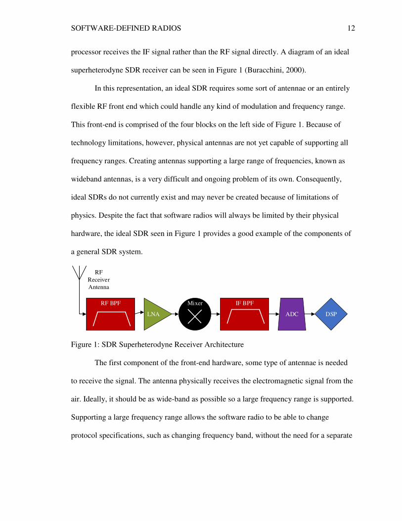
processor receives the IF signal rather than the RF signal directly. A diagram of an ideal
superheterodyne SDR receiver can be seen in Figure 1 (Buracchini, 2000).
In this representation, an ideal SDR requires some sort of antennae or an entirely
flexible RF front end which could handle any kind of modulation and frequency range.
This front-end is comprised of the four blocks on the left side of Figure 1. Because of
technology limitations, however, physical antennas are not yet capable of supporting all
frequency ranges. Creating antennas supporting a large range of frequencies, known as
wideband antennas, is a very difficult and ongoing problem of its own. Consequently,
ideal SDRs do not currently exist and may never be created because of limitations of
physics. Despite the fact that software radios will always be limited by their physical
hardware, the ideal SDR seen in Figure 1 provides a good example of the components of
a general SDR system.
RF
Receiver
Antenna
RF BPF
LNA
Mixer IF BPF
ADC DSP
Figure 1: SDR Superheterodyne Receiver Architecture
The first component of the front-end hardware, some type of antennae is needed
to receive the signal. The antenna physically receives the electromagnetic signal from the
air. Ideally, it should be as wide-band as possible so a large frequency range is supported.
Supporting a large frequency range allows the software radio to be able to change
protocol specifications, such as changing frequency band, without the need for a separate
SOFTWARE-DEFINED RADIOS
antenna. Thus, a wide-band antenna increases the robustness and versatility of its
software radio system.
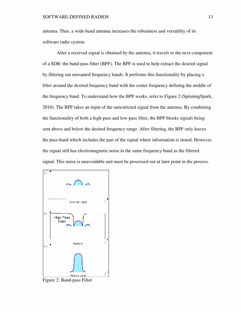
After a received signal is obtained by the antenna, it travels to the next component
of a SDR: the band-pass filter (BPF)
by filtering out unwanted frequency bands.
filter around the desired frequency band with the center frequency defining the middle of
the frequency band. To understand how the BPF works, refer to
2010). The BPF takes an input of the unrestricted signal from the antenna. By combining
the functionality of both a high
sent above and below the desired frequency
the pass-band which includes the part of the signal where information is stored. However
the signal still has electromagnetic noise in the same frequency band as the filtered
signal. This noise is unavoidable a
Figure 2: Band-pass Filter
DEFINED RADIOS
band antenna increases the robustness and versatility of its
received signal is obtained by the antenna, it travels to the next component
pass filter (BPF). The BPF is used to help extract the desired signal
by filtering out unwanted frequency bands. It performs this functionality by placing a
lter around the desired frequency band with the center frequency defining the middle of
the frequency band. To understand how the BPF works, refer to Figure 2
. The BPF takes an input of the unrestricted signal from the antenna. By combining
the functionality of both a high-pass and low-pass filter, the BPF blocks signals being
sent above and below the desired frequency range. After filtering, the BPF only leaves
band which includes the part of the signal where information is stored. However
the signal still has electromagnetic noise in the same frequency band as the filtered
signal. This noise is unavoidable and must be processed out at later point in the process.
pass Filter
13
band antenna increases the robustness and versatility of its
received signal is obtained by the antenna, it travels to the next component
. The BPF is used to help extract the desired signal
It performs this functionality by placing a
lter around the desired frequency band with the center frequency defining the middle of
(SpinningSpark,
. The BPF takes an input of the unrestricted signal from the antenna. By combining
pass filter, the BPF blocks signals being
range. After filtering, the BPF only leaves
band which includes the part of the signal where information is stored. However,
the signal still has electromagnetic noise in the same frequency band as the filtered
nd must be processed out at later point in the process.

SOFTWARE-DEFINED RADIOS 14
After leaving the BPF, the signal passes to the low noise amplifier (LNA). The
LNA amplifies the very low power signal captured from the antennae, so that it can be
processed more easily into a digital signal. When a signal is sent wirelessly over long
distances, the power or strength of the signal degrades heavily. When finally received by
the antenna, the signal is often so low in power that it would be very difficult to process.
Thus, the LNA is necessary for the rest of the signal processing system.
The mixer receives the signal that had been amplified by the LNA. The job of the
mixer is to take the high frequency received signal down to a lower, more manageable
frequency through a process called demodulation (Reed, 2002). This stage of the receiver
is what makes the receiver a superheterodyne receiver rather than a homodyne receiver.
When sent through the air, the transmitted signal is attached to a high frequency carrier
signal through the process of modulation (Cass, 2006). The purpose of this high
frequency carrier signal is to increase the ease of transmitting the signal over long
distances and to transmit the signal over a legally allow frequency range. However,
before the received signal can be processed by a computer, it must be brought back down
to a lower frequency through the use of the mixer.
After being demodulated by the mixer, the signal passes through another BPF.
This band-pass filter blocks all frequencies outside of the signal’s new intermediate
frequency. Note this BPF differs from the previous BPF by the center frequency on
which it focuses. While the RF BPF passes frequencies around the received signal’s
carrier frequency, the IF BPF passes frequencies around the new intermediate center
frequency after leaving the mixer. By doing this, the filter allows only the desired signal
to be further transmitted to the next stage in the SDR receiver.

SOFTWARE-DEFINED RADIOS
Subsequently, the signal travels to
the signal. When the signal is travelling through the air, it exists a
the form of electromagnetic waves. However, computers c
it can only process digital signals. Hence, before being sent to the processor, the signal
must be converted from an analog signal to a digital
transmitted analog signal into a digital
quantizing, by taking samples of the signal at the sampling
those samples by a finite number of binary digits (bits)
Figure 3 shows the analog signal being sampled at discrete time intervals
side of Figure 3 displays the
the amplitude of the signal
and amplitude, the signal can easily be represented by a stream of bits within a computer.
These bits represent the received signal within the computer’
Figure 3: ADC Sampling and Quantization
Finally, the signal
the LNA. The DSP is completely reprogrammable and is what makes the system a
software radio. This special
communication system protoc
DEFINED RADIOS
Subsequently, the signal travels to the analog to digital converter (ADC) receives
the signal. When the signal is travelling through the air, it exists as a continuous signal in
the form of electromagnetic waves. However, computers cannot process an analog signal;
it can only process digital signals. Hence, before being sent to the processor, the signal
must be converted from an analog signal to a digital signal. The ADC converts the
transmitted analog signal into a digital signal, a process known as sampling and
king samples of the signal at the sampling frequency and representing
those samples by a finite number of binary digits (bits) (Tuttlebee, 1999). The left side of
shows the analog signal being sampled at discrete time intervals
displays the quantized version of the signal after discretely representing
the amplitude of the signal (Adamek, 2010). After being represented discretely in ti
and amplitude, the signal can easily be represented by a stream of bits within a computer.
These bits represent the received signal within the computer’s processor.
: ADC Sampling and Quantization
signal is processed by the digital signal processor (DSP)
The DSP is completely reprogrammable and is what makes the system a
special DSP has significant control over the lower layers of the
communication system protocol. More importantly, the DSP performs the final
15
the analog to digital converter (ADC) receives
s a continuous signal in
annot process an analog signal;
it can only process digital signals. Hence, before being sent to the processor, the signal
The ADC converts the
, a process known as sampling and
and representing
. The left side of
shows the analog signal being sampled at discrete time intervals and the right
quantized version of the signal after discretely representing
After being represented discretely in time
and amplitude, the signal can easily be represented by a stream of bits within a computer.
s processor.
is processed by the digital signal processor (DSP) after leaving
The DSP is completely reprogrammable and is what makes the system a
ficant control over the lower layers of the
More importantly, the DSP performs the final

SOFTWARE-DEFINED RADIOS 16
demodulation of the signal from its IF signal to its natural baseband signal. Additionally,
it performs the usual DSP tasks of decoding and understanding the received signal. It can
be implemented on many different pieces of hardware, such as a field programmable gate
array (FPGA) or even a general purpose computer processor.
Homodyne architecture. The architecture of a homodyne or direct conversion
SDR receiver is very similar to its superheterodyne counterpart. In fact, the receiver is
merely missing the several stages of the superheterodyne receiver that convert the RF
signal down to an IF signal. Thus, in this direct conversion receiver, the digital signal
processor receives the RF signal that was sent through the air and has to digitally perform
demodulation of this signal down to baseband. Figure 4 displays an overview of the
homodyne receiver architecture (Buracchini, 2000).
RF
Receiver
Antenna
RF BPF
LNA ADC DSP
Figure 4: SDR Homodyne Receiver Architecture
The blocks the homodyne receiver in Figure 4 shares with the superheterodyne
receiver in Figure 1 function in roughly the same way. Just like in the superheterodyne
receiver, the RF signal is received by an antenna, preferably a wideband antenna. Then,
undesired frequencies are filtered out by the BPF. After that, the LNA amplifies the very
low power received signal. In the superheterodyne receiver, the signal would then be
mixed down to an IF, but in this homodyne receiver, the signal proceeds directly to the
SOFTWARE-DEFINED RADIOS 17
ADC to be digitized. Finally, the DSP receives the signal where it must be digitally
demodulated down from an RF signal to a baseband signal.
Transmitter Architecture
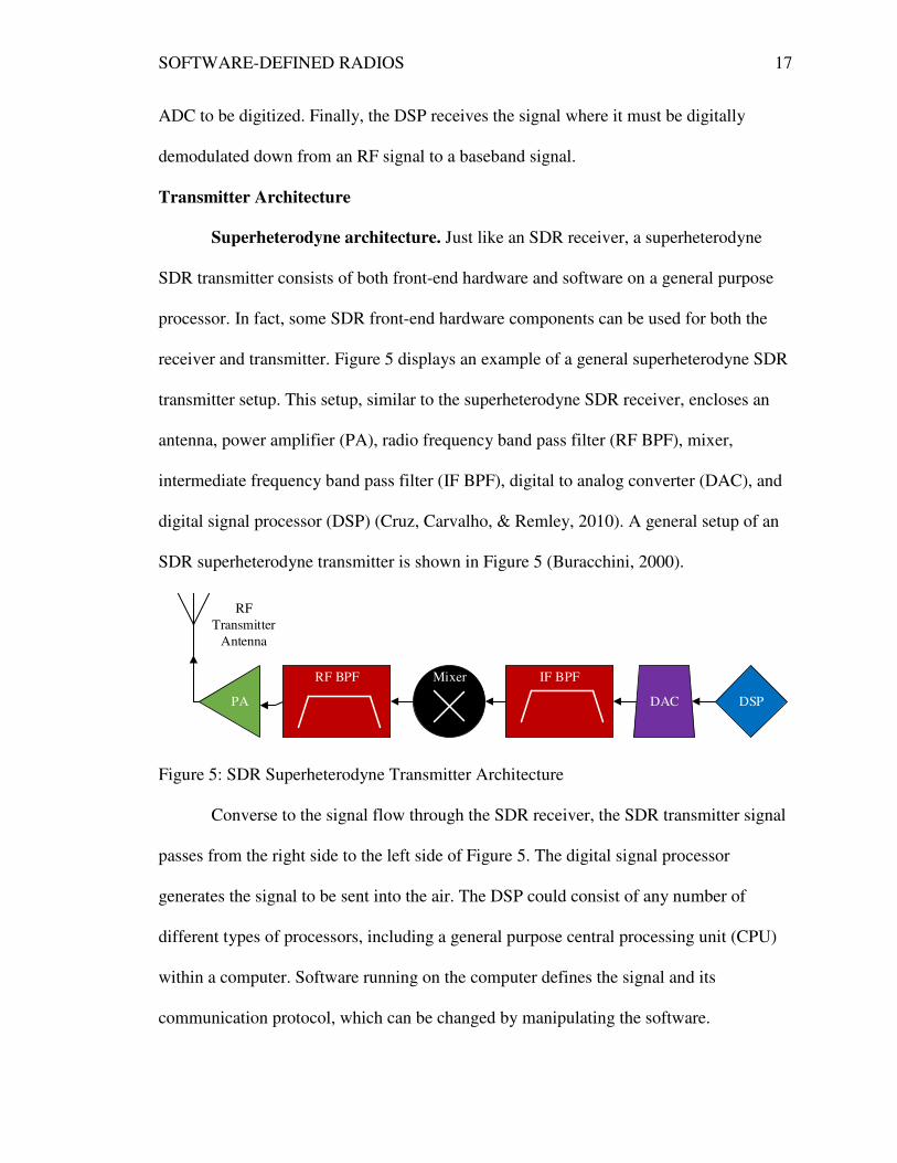
Superheterodyne architecture. Just like an SDR receiver, a superheterodyne
SDR transmitter consists of both front-end hardware and software on a general purpose
processor. In fact, some SDR front-end hardware components can be used for both the
receiver and transmitter. Figure 5 displays an example of a general superheterodyne SDR
transmitter setup. This setup, similar to the superheterodyne SDR receiver, encloses an
antenna, power amplifier (PA), radio frequency band pass filter (RF BPF), mixer,
intermediate frequency band pass filter (IF BPF), digital to analog converter (DAC), and
digital signal processor (DSP) (Cruz, Carvalho, & Remley, 2010). A general setup of an
SDR superheterodyne transmitter is shown in Figure 5 (Buracchini, 2000).
RF
Transmitter
Antenna
RF BPF Mixer IF BPF
DAC DSPPA
Figure 5: SDR Superheterodyne Transmitter Architecture
Converse to the signal flow through the SDR receiver, the SDR transmitter signal
passes from the right side to the left side of Figure 5. The digital signal processor
generates the signal to be sent into the air. The DSP could consist of any number of
different types of processors, including a general purpose central processing unit (CPU)
within a computer. Software running on the computer defines the signal and its
communication protocol, which can be changed by manipulating the software.

SOFTWARE-DEFINED RADIOS 18
Additionally, the DSP performs initial modulation of the signal, taking it from a baseband
signal to a higher frequency IF signal. The versatility of SDRs results from the pliability
of the software running on the DSP.
After being created by the DSP, the signal is received by the digital to analog
converter (DAC). The SDR receiver architecture contained an analog to digital converter
(ADC) which converted the received analog signal into a digital signal for processing
inside the computer. Conversely, the DAC in the SDR transmitter converts the created
digital signal from the processor into analog signal that can be sent over the air
(Tuttlebee, 1999).
Next, the analog signal flows through an intermediate frequency band-pass filter
(IF BPF). This BPF works in the exact same way as the BPF in the SDR receiver, and an
SDR front-end hardware module may use the same filter for both functions. When
generated by the DSP, the signal is sent to the DAC at an intermediate frequency. Then,
the IF BPF cleans up the signal by removing any noise that may have been generated at
unwanted frequencies.
Just as the SDR receiver demodulates the received high frequency signal down to
an intermediate frequency, the SDR transmitter modulates the IF signal up to a high
frequency RF signal. The mixer performs the modulation operation by attaching, or
mixing, the IF signal to a RF carrier signal. For several reasons, the modulation of the
signal to a higher frequency is necessary. For example, higher frequency signals are
easier to transmit over long distances. Also, the Federal Communications Commission
(FCC) regulates who can use different frequency bands in different locations around the
United States. Thus, the signal must be modulated to a frequency band that the
SOFTWARE-DEFINED RADIOS 19
transmitter is legally allowed to use. The frequency band on which the signal is being
sent can be edited through software in an SDR system. While restricted by physical
hardware limitations, SDRs are unique in their ability to change the transmitted signal’s
frequency through the use of software.
Once again, the signal passes through another BPF after being modulated to a
higher frequency. This BPF, like all other BPFs, only passes signals which are within the
desired frequency range and suppresses all others. As the signal is about to be amplified
and sent into the air, sending undesired noise from other frequency ranges into the air
could cause problems for other wireless communication systems. Transmitting
information over more than the allotted frequency range can disrupt communications
within those frequencies and may also be illegal. Thus, the performance of the RF BPF is
essential to the functionality of the SDR transmitter.
Right before transmission over the air through the antenna, the signal must be
amplified by a power amplifier (PA). The PA uses a series of electrical circuits to
dramatically increase the power of the transmitted signal (Cruz, Carvalho, & Remley,
2010). When within the DSP and in previous stages, the signal resides at very low power
levels. Digital circuits require low signals to increase efficient and to not destroy sensitive
components. As the signal degrades in strength very quickly through the air, it must leave
the transmitter at a very high power to compensate for in-air losses.
The final stage of the SDR transmitter architecture, the antenna, physically sends
the signal into the air. To make the SDR robust, the antenna must be as wideband as
possible or be able to transmit over a wide range of frequencies. Wideband antennas
allow SDRs to change communication protocols from one frequency band to another with
SOFTWARE-DEFINED RADIOS 20
much ease. Otherwise, a developer would need to change antennas for communication
systems using different frequencies. Consequently, the RF antenna performs one of the
most important functions in any SDR system.
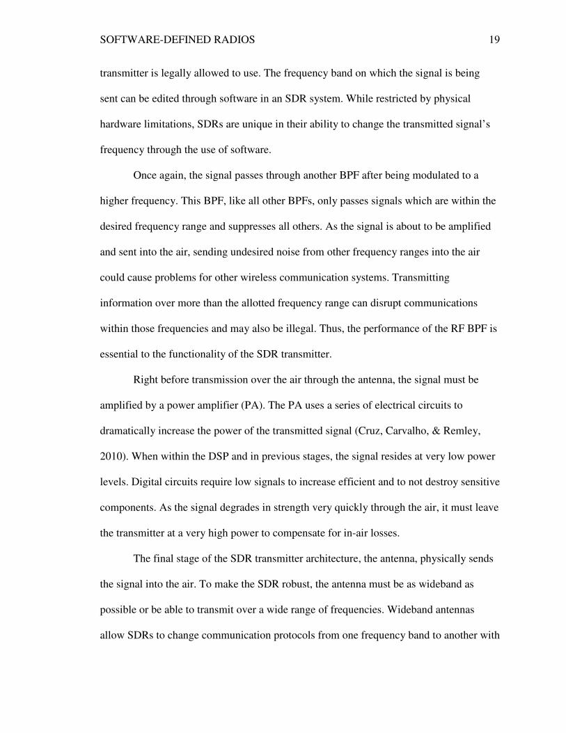
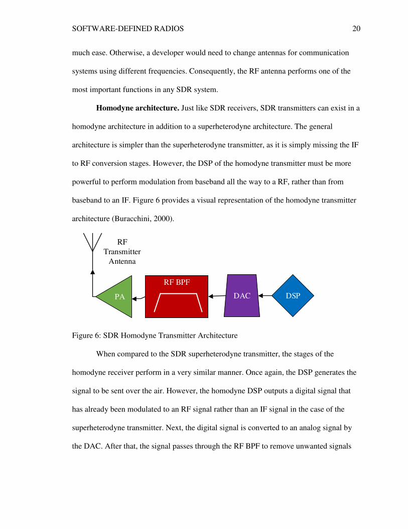
Homodyne architecture. Just like SDR receivers, SDR transmitters can exist in a
homodyne architecture in addition to a superheterodyne architecture. The general
architecture is simpler than the superheterodyne transmitter, as it is simply missing the IF
to RF conversion stages. However, the DSP of the homodyne transmitter must be more
powerful to perform modulation from baseband all the way to a RF, rather than from
baseband to an IF. Figure 6 provides a visual representation of the homodyne transmitter
architecture (Buracchini, 2000).
RF
Transmitter
Antenna
RF BPF
DAC DSPPA
Figure 6: SDR Homodyne Transmitter Architecture
When compared to the SDR superheterodyne transmitter, the stages of the
homodyne receiver perform in a very similar manner. Once again, the DSP generates the
signal to be sent over the air. However, the homodyne DSP outputs a digital signal that
has already been modulated to an RF signal rather than an IF signal in the case of the
superheterodyne transmitter. Next, the digital signal is converted to an analog signal by
the DAC. After that, the signal passes through the RF BPF to remove unwanted signals

SOFTWARE-DEFINED RADIOS 21
from being transmitted into the air. Then, just before transmission, the signal is amplified
by the PA. Finally, the amplified signal is transmitted into the air through the antenna.
Software-Defined Radio Development Systems
While all SDR systems follow the basic receiver and transmitter structure
previously discussed, actual software radio systems differ in their implementation
structure. In particular, SDR systems can exist as a combination of proprietary and open
source hardware and software. More specifically, SDR systems can be developed in one
of three primary ways: developing proprietary software for different hardware platforms,
creating a standard hardware platform, or using compilers to enable the same code to
work on multiple hardware systems (Buracchini, 2000).
As previously explained, software radio systems consist of a hardware front-end
and software for processing. Consequently, the development of SDR systems is often
split between those working on hardware front-ends and the software to develop SDRs.
In many cases, one hardware unit will be compatible with multiple SDR development
software packages. However, the SDR software packages are often created specifically
for use with a particular front-end hardware module. The proceeding sections will outline
the major SDR hardware units and software packages.
Software-Defined Radio Hardware
Universal software radio peripheral. One of the most popular SDR front-end
hardware modules, the Universal Software Radio Peripheral (USRP), is a software radio
platform developed and sold by Ettus Research, LLC under the parent company of
National Instruments (Cass, 2006). Its main goal is to enable users to create their own
SDRs, and it is used predominantly by researchers and universities. The key advantages
SOFTWARE-DEFINED RADIOS 22
of the USRP are its versatility, large development community, and high amount of
associated software (Dickens, Dunn, & Laneman, 2008).
In general, the USRP hardware unit consists of an antenna connected to an radio
frequency (RF) front end, analog to digital converter (ADC), digital to analog converter
(DAC), and a field programmable gate array (FPGA) (Cass, 2006). Then, the USRP
connects to a host compute via either a USB or Gigabit Ethernet connection, depending
on the USRP model (Tucker & Tagliarini, 2009). The USRP is compatible with nearly all
modern operating systems (OS) including Window, Mac OS X, and many distributions of
UNIX. Thus far, UNIX distributions have been by far the most commonly used OS used
with the USRP, primarily because of Linux’s open source nature. To communicate with
the host computer, the USRP board works with the USRP Hardware Driver (UHD).
More precisely, the USRP is not merely one product but is actually a family of
products. Each of these USRP boards differs in terms of features offered and supported.
Currently, Ettus Research produces four main lines of USRP boards. First, the high end
hardware boards, the USRP X Series, are some of the most robust and fastest software
radio front-ends in existence (Ettus Research, 2014). Second, the most widely used USRP
boards are part of the USRP Networked Series (N Series). The USRP N Series boards are
relatively robust and connect to a host computer using a high speed Gigabit Ethernet
connection (Ettus Research, 2014). Third, the USRP Bus Series consists merely of a
single circuit board without a protective casing like the other USRP models. It is
primarily for use in low cost, small form factor software radio designs (Ettus Research).
The fourth and final USRP line, known as the USRP Embedded Series, is made up of
both a hardware front-end and a built-in processer. Instead of connecting to a host

SOFTWARE-DEFINED RADIOS 23
computer, the Embedded Series boards host an on-board Linux operating system (Ettus
Research).
Despite their differences, each USRP model contains some major basic features.
Primarily, each model consists of a basic motherboard and a removable daughterboard
(Ferreira, Diniz, Veiga, & Carneiro, 2012). The daughterboard performs RF front end
functions and can be interchanged to allow receiving and transmitting (RX and TX) at
different frequencies. However, the daughterboards currently on the market are wideband
enough that one daughterboard can suffice for many different radio protocols. After being
processed by the daughterboard, the signal moves to the motherboard where an ADC
changes the analog signal into a digital signal. It also contains an FPGA to provide some
DSP functions, but the bulk of the digital processing is done on the host processor which
is connected via a USB or Gigabit Ethernet cable.
From the connection to the computer, the USRP device communicates with the
host computer using the USRP Hardware Driver (UHD). Additionally, it has support for
all major platforms: Windows, UNIX, and Mac OS X. Moreover, the UHD works with
many third-party software platforms such as GNU Radio, Labview, Simulink, and
OpenBTS. Because the UHD is universal across all USRP boards, applications written
for one USRP board is compatible with all other USRP models. This versatility increases
the usefulness and robustness of the USRP platform, since developers do not have to
worry about the many different USRP models when designing radios. Consequently,
researchers have gravitated to the USRP as a good development system for new radio
protocol when developing with a large array of researchers.
SOFTWARE-DEFINED RADIOS 24
FlexRadio systems. While the USRP is one of the most widely used SDR
hardware units for academic and research use, the FlexRadio System is one of the most
popular SDR units for amateur, home, and personal use. FlexRadio sells a variety of SDR
hardware units, ranging in low-end, cost efficient models to expensive high-performance
models (FlexRadio Systems, 2011). These radios are all designed for use with modern
Microsoft Windows operating systems (FlexRadio Systems). Finally, all FlexRadios are
designed for use with the FlexRadio PowerSDR software radio development system.
Unlike some other SDR hardware units, FlexRadio systems are limited to
standard amateur radio frequency bands. The FCC regulates who can use different radio
frequency bands, and in order to comply with these regulations, FlexRadio manufacturers
have to limit their radios’ operating range. Therefore, FlexRadio systems would not be
ideal for use in developing and testing communication standards which can exist on a
much wider frequency range than those possible with the FlexRadio systems. It should be
noted, however, that FlexRadio systems were not designed for research and scientific use,
so its frequency band limitation was a design choice.
FUNcube dongle. The FUNcube Dongle is a low-cost, SDR receiver primarily
created for educational and amateur purposes. Consisting of a very small USB dongle,
the FUNcube allows users access to a limited frequency band between 150 kHz and 1.9
GHz (FUNcube Dongle, 2013). The FUNcube Dongle is simple in that it can begin
working within minutes and can work with several different software radio packages,
including GNU Radio. In addition to the USB connection to a computer, the FUNcube
Dongle has a SMA connection to the desired external antenna (FUNcube Dongle). While
SOFTWARE-DEFINED RADIOS 25
not very robust, the FUNcube Dongle provides simple and cheap SDR capabilities in a
small form factor.
Software-Defined Radio Software
GNU radio. One of the most used software packages for creating SDRs, GNU
Radio is an open source software platform used to design and implement software radios
(Dhar, George, Malani, & Steenkiste, 2006). It runs on desktop computers, mainly on
distributions of the Linux operating system, to process and analyze signals in a SDR.
GNU Radio is specifically designed and maintained for use with the USRP platform,
interacting with the UHD to communicate with the USRP board. However, GNU Radio
is also compatible with many other hardware front-ends.
GNU Radio works by breaking down digital signal processing into blocks and
connections between those blocks. More specifically, GNU Radio describes its
functionality as implementing “the signal processing runtime and processing blocks to
implement software radios” (GNU Radio, 2011). The signal processing library of GNU
Radio provides signal processing blocks for modulation, demodulation, filtering, I/O
operations such as file access and audio output, and for communicating with the USRP
board (Dhar, George, Malani, & Steenkiste, 2006). These blocks all have declared inputs
and outputs, and connections are defined between inputs and outputs of different blocks
to create a signal processing flow. GNU Radio can be used to write application to both
receive data and transmit data using the connected USRP platform.
GNU Radio applications are primarily created using the Python and C++
programming languages. GNU Radio signal processing blocks are written primarily in
C++ for high speed applications, while the blocks are connected together using Python

SOFTWARE-DEFINED RADIOS 26
(Marwanto, Sarijari, Fisal, Yusof, & Rashid, 2009). The blocks of GNU Radio are
connected to form a flow graph through which the signal flows on a systems level (Dhar,
George, Malani, & Steenkiste, 2006). The flow graphs can either be represented through
just source code by an executable Python script or through a graphic user interface known
as GNU Radio Companion (GRC).
Blocks usually operate on continuous streams of data, and every GNU Radio
system has at least one input stream known as a source and at least one output stream
known as a sink. Sources and sinks are special blocks which only produce or consume
data, respectively (Dhar, George, Malani, & Steenkiste, 2006). Sources include blocks
that receive data from USRP RX ports and blocks that read from file descriptors (Dhar,
George, Malani, & Steenkiste). Some sinks include blocks that send data to USRP TX
ports and block that write to file descriptors (Dhar, George, Malani, & Steenkiste). In
general, anything that a block outputs is known as an item, and these items can be real
samples, complex samples, integers, etc. Each block operates on its input stream to
produce an output stream, which may or may not be of the same data type. The blocks
work together to form a SDR system.
This flow graph can be visualized on the computer by using the GNU Radio
Companion (GRC), which is a graphical user interface (GUI) for generating and
visualizing flow graphs. The blocks each serve a single function to increase the
modularity of the SDR system and are connected together to form a total system. The
blocks are connected together by ports defined by the user (Dhar, George, Malani, &
Steenkiste, 2006). The first block, the source, does not have an input port, because it
produces the input signal. Likewise, the last block, the sink, does not have an output port,
SOFTWARE-DEFINED RADIOS 27
as the last block contains data that gets recorded. Each block has different parameters
which the user can set, including sample rate, gain, frequencies, etc. depending on the
block.
GNU Radio has an extensive library of built-in signal processing blocks and
example programs but also allows users to develop their own blocks and radio systems
(Dhar, George, Malani, & Steenkiste, 2006). When developing an SDR system with
GNU Radio, users have access to many signal processing blocks that come standard with
GNU Radio. In addition to the built-in blocks, users can develop their own blocks, known
as out-of-tree modules, to implement more advanced functionality. Because of the open
source nature of GNU Radio, when new blocks and flow graphs are created, they are
often placed online for others to view and use. The extensive development community
using GNU Radio in combination with the robustness of the program has made GNU
Radio a favorite for academic researchers and software radio developers.
MATLAB and Simulink. MATLAB and Simulink have a free to download
package that enables use with the Ettus Research USRP front-ends (Tabassam, Ali,
Kalsait, & Suleman, 2011). Requiring the Communication Systems Toolbox, a separate
paid pack in addition to owning MATLAB and Simulink, the USRP development
package allows user to create and test SDRs with a USRP front-end (Mathworks, 2014).
Simulink communicates with the USRP through the use of the UHD, which is the main
driver for USRP devices. As MATLAB and Simulink are available for all major
operating systems, this software package can be used to create SDRs using a Microsoft
Windows, Mac OS X, or Linux based computer. For those who are already experienced
SOFTWARE-DEFINED RADIOS 28
using MATLAB and Simulink, the USRP support could make this a good development
platform for software radios.
Labview. Another major software radio development kit for use with the USRP
system is Labview, developed by National Instruments. Labview is a widely used paid
program for designing systems using a kind of visual programming language. To connect
with the USRP, Labview has a freely downloadable software add-on that communicates
with the USRP using the UHD (National Instruments, 2011). Similar to the other GUIs
for use with the USRP, such as GNU Radio and Simulink, Labview provides the ability
to program the USRP through a signal flow graph (Welch & Shearman, 2012). Thus, for
those familiar with using Labview, developing SDRs using the USRP hardware platform
can be quite simple.
OSSIE. Developed by researchers at Virginia Tech, the Open Source SCA
Implementation::Embedded (OSSIE) is a SDR development program primarily for use
with the USRP platform (OSSIE, 2013). OSSIE provides a GUI that runs exclusively on
Linux operating systems. Originally, OSSIE was developed to be modeled after the JTRS
Software Communications Architecture, which was to be the software radio architecture
standard for the United States military (Li, Jha, & Raghunathan, 2012). While built-in
modules are available for signal processing, users can create their own signal processing
modules through programming with C++. With highly customizable flow graphs and a
GUI somewhat similar to GNU Radio Companion, OSSIE has become one of the
premiere software radio development packages used by researchers and developers.
FlexRadio PowerSDR. Designed for use primarily with FlexRadio’s own
hardware modules, the FlexRadio PowerSDR system offers amateurs a graphic interface
SOFTWARE-DEFINED RADIOS 29
for creating their own software radios (FlexRadio Systems, 2011). As it is used mainly by
FlexRadio systems, PowerSDR is a software package developed by FlexRadio.
Additionally, FlexRadio encourages software radio experimentation and development by
offering users the ability to view and edit the program’s source code (FlexRadio
Systems). However, programming experience is not necessary to operate the FlexRadio
PowerSDR software, as its fully-functional graphic user interface (GUI) can provide most
software radio functions. FlexRadio PowerSDR is a Microsoft Windows based software
package that allows users to customize the digital signal processing of their software
radio (FlexRadio Systems). The PowerSDR software allows the user to specify all
aspects of the signal processing within the host computer, including modulating and
demodulation, frequency bands to be used, etc.
The State of Software Radio Technology
Current State
Up to this point, SDRs have primarily been used by researchers and developers
for designing and testing communication systems. The primary motivations for this focus
on SDR’s immense potential. While the government has explored and used SDRs for
military use, they have not yet fully adopted SDRs into their communication systems.
Additionally, many users have explored using SDRs in amateur radio networks to easily
communicate through a variety of methods. However, developing SDR systems can be
too technical and too expensive for the average consumer, so widespread SDR adoption
has yet to occur with cheaper and simpler radio configurations readily available. Many of
these limitations are only current problems that researchers hope to solve in the future.
SOFTWARE-DEFINED RADIOS 30
One of the most challenging complications with SDR systems thus far has
involved the latency and low throughput of systems processing information in a general-
purpose computer. As the processing hardware used in SDR systems is general purpose
in nature, it will always be less efficient than its hardware-defined counterpart. To create
a robust and dynamic system that can recreate many different kinds of radio systems, a
large amount of both hardware and software overhead must be implemented.
An example of the latency problem occurs in the Universal Software Radio
Peripheral used with GNU Radio. As several different systems must be connected
together with busses in a USRP/GNU Radio system, it experiences some bottlenecking in
different components that produces latency (Truong, Suh, & Yu, 2013). In fact, Truong,
Suh, & Yu identified, “Latency on GNU Radio/USRP platforms can be divided into three
components: (i) latency introduced in GNU Radio and OS kernel, (ii) latency at
communication bus between host computer and USRP, and (iii) latency at USRP
hardware” (p. 307). Latency in USRP/GNU Radio systems has inhibited some modern
communication protocols, such as 802.11a/g/n, from being implemented. To combat this,
researchers have explored options such as implementing time-critical components
entirely within dedicated hardware or even within an FPGA on the front-end hardware
module (Puschmann, Kalil, & Mitschele-Thiel, 2012). These solutions are non-ideal, as
they undermine the flexibility and robustness inherent in SDRs. More recently, however,
some researchers have found workarounds for implementing time-critical mechanisms
through careful programming, such as the carrier sense multiple access (CSMA)
mechanism developed by Puschmann, et al. for the USRP.

SOFTWARE-DEFINED RADIOS 31
As SDR systems still have significant problems implementing high data-rate,
time-critical applications, only the highest-end SDR systems are being used
commercially. As such, software radios have been used in radio base-stations which have
the space and money to afford expensive, high-end processors. The added benefit of
using SDRs in base-stations is that companies would not have to spend a lot of time and
money to upgrade communication protocols in these base-stations. Rather than needing
new equipment each time an improvement in the radio technology is introduced, the
company would simply have to change some source code. Consequently, companies
could keep up with current technology even faster.
Future State
While some consumer-based SDR systems currently exist, most are not easy
enough to use for the average consumer. Therefore, the future of SDR adoption lies in
making them robust and easy to use for non-technical users. Then, many developers are
working to make simple, cheap, and small software radios that can be easily modified and
used by consumers. This is not the ultimate goal of software radio systems, however, as
researchers hope SDRs can provide advanced functionality impossible in classical
hardware radios.
One of the main goals of software radios is create a new, advanced radio system
known as cognitive radio. As previously mentioned, cognitive radios are “smart” in that
they can observer their environment and change themselves accordingly. Joseph Mitola
(1999) provides an even clearer picture of cognitive radios in his doctoral dissertation
when he states, “Such a radio should be aware of the communications needs of its user,
the overall context of anticipated communications events, and the degree of success

SOFTWARE-DEFINED RADIOS 32
towards communications goals offered by alternative courses of action” (p. 39). From
this, one can see that cognitive radios must have the ability to physically alter their
configuration based on communications context. Since hardware radios are essentially
static, the only hope for cognitive radios is in the development of more efficient and
smarter SDRs. Researchers at Virginia Tech, especially, have been working on creating
cognitive radios through SDRs (MacKenzie, et al., 2009). So far, they have made some
important developments toward cognitive radios, but the research community still has
significant challenges to overcome before cognitive radios will become fully-realized.
The benefits of a cognitive radio system can be readily seen. Primarily, cognitive
radios could allow frequency bands to be allocated dynamically instead of statically.
Classically, RF bands have been sold or given out by governments to different entities to
use so that industries and governments can send wireless communications without
interference (MacKenzie, et al., 2009). While this model has worked, it is very
inefficient, as many frequency bands sit unused for long periods of time. However,
cognitive radios give hope for dynamic spectrum access (DSA), which would allow
radios to either make sure a frequency band is free before using it or negotiate for a
frequency band from some sort of frequency broker (MacKenzie, et al.). This solution
would lead to much more efficient use of the frequency spectrum and would alleviate
some of the frequency crowding problem experienced today.
Another future goal of software radios centers on the creation of an ideal, fully
software-based transceiver. An ideal software receiver would be able to directly sample
the received RF signal to convert it to a digital signal. Additionally, a fully software
transceiver would need to be able to implement a software-defined antenna that could
SOFTWARE-DEFINED RADIOS 33
change its frequency range through software manipulation. The direct conversion
transceiver has been very difficult to implement, because very high sampling rates are
needed by the analog to digital converter. Significant work on developing a direct-
sampling receiver has been done by Akos, Stockmaster, Tsui, and Caschera (1999).
In addition to developing robust direct-conversion transceivers, software radios of
the future will also ideally have software-defined antennas. A software-defined antenna
works by being reconfigurable within software. Unfortunately, software antennas only
currently exist in rudimentary forms and still have many barriers to overcome before
becoming a viable antenna option. However, researchers have demonstrated some basic
software antenna functionality which gives them hope for the future of software-defined
antennas (Grau, Romeu, Jofre, & De Flaviis, 2008). Reconfigurable antennas could help
software radio systems dramatically. By focusing on a particular frequency band, a SDR
system with a software antenna could more easily extract the received signal with
minimal noise and outside interference. Thus, software-defined antennas will be an
important technological element of future SDRs.
Software-Defined Radio Example Implementations
Since software radios have been introduced, researchers have developed many
fully-functional SDR systems that can replace traditional hardware radios. Some of these
implantations are quite basic, such as AM and FM receivers, and serve as a good
educational and entertainment tool for those new to SDRs. Other SDR implementations
have recreated communication protocols in software that were originally only creatable
using hardware. Additionally, some SDR researchers have developed wireless test-beds
for new communication protocols. Robust and changeable protocol test-beds were not
SOFTWARE-DEFINED RADIOS 34
previously possible because of the inherently static nature of hardware radios. Finally,
many SDR developers are focusing on developing cognitive radios which have the ability
to understand their surroundings and make protocol changes on the fly. An overview of
several of these SDR implementations will be included in the following sections.
IEEE 802.11a/g/p
One of the most important SDR implementations thus far has been the IEEE
802.11a/g/p receiver, which is the basis for Wi-Fi communications used today.
Developed using GNU Radio and the USRP board, this SDR receiver was one of the first
orthogonal frequency division multiplexing (OFDM) based systems developed within
software (Bloessl, Segata, Sommer, & Dressler, 2013). Specifically, this system
implements both the physical and MAC layers of IEEE 802.11a/g/p (Bloessl, Segata,
Sommer, & Dressler). The ability to implement a Wi-Fi standard within software
provides a significant milestone for SDRs in general, as Wi-Fi is one of the most well-
known and researched wireless communication systems. In the end, this system could be
used to test the lower layers of IEEE 802.11a/g/p under different conditions and lay the
groundwork for future SDR protocol development.
GPS Receiver
A non-real time global positioning system (GPS) receiver has been developed
using the USRP with GNU Radio (Thompson, Clem, Renninger, & Loos, 2012). In this
implementation, the GPS receiver uses an extra hardware module external to the USRP to
step down the very high frequency GPS signal to a lower intermediate frequency
(Thompson, Clem, Renninger, & Loos). Some other basic SDR GPS systems have been
implemented, but the choice was made for this system to not operate in real time for
SOFTWARE-DEFINED RADIOS 35
simplicity of processing and so different GPS receiver algorithms could be tested
(Thompson, Clem, Renninger, & Loos). While the GPS does not operate in real time,
developing a GPS system is a significant development for the SDR community.
OpenBTS
OpenBTS is an open source GSM SDR emulator developed with the USRP and
GNU Radio (Pace & Loscri, 2012). GSM is a well-known cellular voice communication
standard. The OpenBTS project has been collaboratively developed by many researchers
over the internet. It allows GSM compatible cellular phones to access the GSM network
by making the USRP into a GSM access point. Then, the voice is sent through a voice
over IP (VoIP) network (Pace & Loscri). The end goal of this project is to provide a low-
cost cellular network that can be deployed in remote areas (OpenBTS, 2013).
Conclusions
Software-defined radios offer extensive advantages and features that have
attracted researchers over the past few years. Because of their modularity, versatility, and
digital nature, many new radio systems are being developed within software rather than
hardware. Consisting of a versatile front-end hardware module, the signal processing of
SDRs is often conducted within a general purpose processor with a computer. Likewise,
some of the most accepted SDR units thus far have been Ettus Research’s USRP board
and GNU Radio software system, because of the open source nature, large development
community, and ease of customization. As front-end hardware and general purpose CPUs
continue to become more robust, developers will continue to implement more advanced
software radios. As such, SDRs will become an even more important and influential part
of society in the years to come.

SOFTWARE-DEFINED RADIOS 36
References
Adamek, P. (2010, July 6). File: Sampled.signal.svg. Retrieved from Wikimedia
Commons: http://en.wikipedia.org/wiki/File:Sampled.signal.svg
Akos, D. M., Stockmaster, M., Tsui, J. B., & Caschera, J. (1999, July). Direct bandpass
sampling of mulitple distinct RF signals. IEEE Transactions on Communications,
47(7), 983-988.
Bloessl, B., Segata, M., Sommer, C., & Dressler, F. (2013). Decoding IEEE 802.11a/g/p
OFDM in software using GNU Radio. 19th ACM International Conference on
Mobile Computing and Networking (MobiCom 2013), Demo Session (pp. 159-
161). Miami: ACM. doi:10.1145/2500423.2505300
Buracchini, E. (2000, September). The software radio concept. IEEE Communications
Magazine, pp. 138-143.
Cass, S. (2006, October). Hardware for your software radio. IEEE Spectrum, pp. 53-56.
Corgan, J. (2013). GNU Radio: Core concepts. (GNU Radio) Retrieved May 4, 2013,
from
http://gnuradio.org/redmine/projects/gnuradio/wiki/TutorialsCoreConcepts#So-
what-does-GNU-Radio-do
Cruz, P., Carvalho, N. B., & Remley, K. A. (2010, June). Designing and testing software-
defined radios. IEEE Microwave Magazine, pp. 83-94.
Dhar, R., George, G., Malani, A., & Steenkiste, P. (2006). Supporting integrated MAC
and PHY software development for the USRP SDR. 1st IEEE Workshop on
Networking Technologies for Software Defined Radio Networks (pp. 68-77).
IEEE.
SOFTWARE-DEFINED RADIOS 37
Dickens, M. L., Dunn, B. P., & Laneman, J. N. (2008, August). Design and
implementation of a portable software radio. IEEE Communications Magazine,
pp. 58-66.
Ettus Research. (2014). USRP bus series. Retrieved from Ettus Research:
https://www.ettus.com/product/category/USRP-Bus-Series
Ettus Research. (2014). USRP embedded series. Retrieved from Ettus Research:
https://www.ettus.com/product/category/USRP-Embedded-Series
Ettus Research. (2014). USRP networked series. Retrieved from Ettus Research.
Ettus Research. (2014). USRP x series. Retrieved from Ettus Research:
https://www.ettus.com/product/category/USRP-X-Series
Ferreira, P. V., Diniz, P., Veiga, A., & Carneiro, M. (2012). Frequency response
acquisition of a digital radio transceiver using USRP module and GNU Radio
software. Fourth International Conference on Computational Intelligence,
Modelling and Simulation (pp. 243-248). IEEE Computer Society.
FlexRadio Systems. (2011, August 1). Frequently asked questions. Retrieved from
FlexRadio Systems: http://www.flexradio.com/Products.aspx?topic=faq
FlexRadio Systems. (2013). FlexRadio PowerSDR features and capabilities. Retrieved
from FlexRadio Systems:
http://www.flexradio.com/Products.aspx?topic=PowerSDRv2
FUNcube Dongle. (2013, December). Funcube dongle. Retrieved from FUNcube
Dongle: http://www.funcubedongle.com/
GNU Radio. (2011). GNU Radio overview. (GNU Radio) Retrieved May 4, 2013, from
http://gnuradio.org/redmine/projects/gnuradio

SOFTWARE-DEFINED RADIOS 38
Grau, A., Romeu, J., Jofre, L., & De Flaviis, F. (2008). A software defined MEMS-
reconfigurable PIXEL-antenna for narrowband MIMO systems. NASA/ESA
Conference on Adaptive Hardware and Systems (pp. 141-146). Noordwijk: IEEE
Computer Society. doi:10.1109/AHS.2008.74
Li, C., Jha, N. K., & Raghunathan, A. (2012, March). Secure reconfiguration of software-
defined radio. ACM Transactions on Embedded Computing Systems, 11(1), 10-22.
MacKenzie, A. B., Reed, J. H., Athanas, P., Bostian, C. W., Buehrer, R. M., DaSilva, L.
A., . . . da Silva, C. R. (2009, April). Cognitive radio and networking research at
Virginia Tech. Proceedings of the IEEE, 97(4), 660-688.
doi:10.1109/JPROC.2009.2013022
Marwanto, A., Sarijari, M. A., Fisal, N., Yusof, S., & Rashid, R. A. (2009). Experimental
study of OFDM implementation utilizing GNU Radio and USRP - SDR. 9th
Malaysia International Conference on Communications (pp. 132-135). Kuala
Lumpur, Malaysia: IEEE.
Mathworks. (2014). USRP support package from communications system toolbox.
Retrieved from Mathworks: http://www.mathworks.com/hardware-
support/usrp.html
Mitola, J. (1999, August). Cognitive radio: Model-based competence for software radios.
Royal Institute of Technology.
National Instruments. (2011, September). NI-USRP 1.0. Retrieved from National
Instruments: http://www.ni.com/download/ni-usrp-1.0/2679/en/
OpenBTS. (2013). What is OpenBTS? Retrieved from OpenBTS: http://openbts.org/
SOFTWARE-DEFINED RADIOS 39
OSSIE. (2013). About open source SCA implementation: Embedded (OSSIE). Retrieved
from OSSIE: http://ossie.wireless.vt.edu/trac/wiki/About
Pace, P., & Loscri, V. (2012). OpenBTS: A step forward in the cognitive direction. 2012
21st International Conference on Computer Communications and Networks
(ICCCN) (pp. 1-6). Munich: IEEE.
Puschmann, A., Kalil, M. A., & Mitschele-Thiel, A. (2012). A flexible CSMA based
MAC protocol for software defined radios. Frequenz, 66, 261-268.
doi:10.1515/freq-2012-0048
Reed, J. H. (2002). Software radio: A modern approach to radio engineering. Upper
Saddle River, NJ: Prentice Hall.
SpinningSpark. (2010, July 2). Passband schematic 3. Retrieved from Wikimedia
Commons: http://en.wikipedia.org/wiki/File:Passband_schematic3.png
Tabassam, A. A., Ali, F. A., Kalsait, S., & Suleman, M. U. (2011). Building software-
defined radios in MATLAB Simulink: A step toward cognitive radios. 2011
UKSim 13th International Conference on Modelling and Simulation (pp. 492-
497). IEEE Computer Society.
Thompson, E. A., Clem, N., Renninger, I., & Loos, T. (2012). Software-defined GPS
receiver on USRP platform. Journal of Network and Computer Applications, 35,
1352-1360.
Tribble, A. C. (2008). The software defined radio: Fact and fiction. 2008 IEEE Radio and
Wireless Symposium (pp. 5-8). Orlando, FL: IEEE.
SOFTWARE-DEFINED RADIOS 40
Truong, N. B., Suh, Y.-J., & Yu, C. (2013). Latency analysis in GNU Radio/USRP-based
software radio platforms. IEEE Military Communications Conference (pp. 305-
310). San Diego: IEEE. doi:10.1109/MILCOM.2013.60
Tucker, D. C., & Tagliarini, G. A. (2009). Prototyping with GNU Radio and the USRP -
where to begin. IEEE Southeastcon 2009 (pp. 50-54). Atlanta, GA: IEEE.
Tuttlebee, W. H. (1999, April). Software-defined radio: Facets of a developing
technology. IEEE Personal Communications, pp. 38-44.
Welch, T. B., & Shearman, S. (2012). Teaching software defined radio using the USRP
and Labview. IEEE International Conference on Acoustics, Speech and Signal
Processing (pp. 2789-2792). IEEE.