studies on (i) characterization of bremsstrahlung spectra...
TRANSCRIPT
Chapter 1.
Introduction
This chapter discusses importance and objective of the
work in the field of electron accelerator based research
for medical as well as industrial applications. The Race-
Track Microtron at Pune University and Linear
Accelerator at SAMEER, Mumbai are discussed with
h i ifi i d ki i i l f d itheir specifications and working principle for production
of high energy electrons. Apart from this, an interaction
of electrons with matter along with an emphasis on the
generation of bremsstrahlung radiation is discussed ingeneration of bremsstrahlung radiation is discussed in
great detail. In addition, an interaction of gamma
radiation is discussed in view of the generation of
neutrons through photo nuclear reactions alongwith the
interaction of neutrons with matter. The Monte Carlo
based FLUKA code, has been explained with minute
details. Moreover, to set an overview of the thesis, a
summary of the thesis is finally incorporatedsummary of the thesis is finally incorporated.
1

Chapter 1. Introduction 2
1.1 Importance and Objective
Although not published until 1897, J. J. Thomson’s work on cathode
rays and consequent discovery of the electron preceded Roentgen’s discovery
of X-rays in the November of 1895 - a year before the announcement by the
Becquerel of the discovery of radioactivity. The experts were therefore, aware
that X-rays had been produced by a primitive electron accelerator. X-rays were
immediately applied to diagnosis and therapy in medicine. In 1903, Coolidge
developed hot cathode X-ray tube. Since the inception of radiotherapy, the tech-
nology of radiation production has first been aimed to get higher photon and elec-
tron beam energies and intensities, and more recently towards computerization
and intensity modulated beam delivery. During the first 50 years of radiother-
apy, the technological progress was relatively slow and mainly based on X-ray
tubes, Van de Graaff generators and betatrons. The Co-60 gamma radiation unit
was invented by H.E. Johns in Canada in the early 1950s for radiotherapy. The
concurrently developed medical linacs, became the most widely used radiation
source in modern radiotherapy. With its compact and efficient design, the linac
offers excellent versatility for use in radiotherapy through isocentric mounting
and provides either electron or megavoltage X-ray therapy with a wide range of
energies.
Presently, there are more than ten thousand of accelerators running all
over the world. Out of which almost fifty percent are devoted to the medical ap-
plications. The main areas of use are radioisotopes production, radiography and
conventional radiotherapy with electron and photon beams. Electrons and pho-
tons are found to be good members of radiation therapy for treating the cancer,
quite years ago. This is because of their high penetrability, low Linear Energy
Transfer (LET) to exhibit damage to the normal cell and unique characteristics
of dose distribution at depth. With the advent of high energy linear and circular
accelerators, electron / photon have become a viable option in treating superfi-
cial tumors up to the depth of about 5-10 cm. In such case, the dose of radiation
absorbed correlates directly with the energy of the beam and its deposition of

Chapter 1. Introduction 3
energy in tissues, which results in damage to DNA strands and diminishes the
cell’s ability to replicate indefinitely. For low LET radiations, the damage is in-
duced primarily by activated radicals produced from atomic interactions. Over
the energy range of therapeutically used X-rays, typically 100 keV to 25 MeV,
approximately the same physical dose needs to be delivered at different energies
to reach a given biological endpoint, resulting in similar Relative Biological Ef-
fectiveness (RBEs). High LET radiations such as protons, neutrons, however,
result in biological damage that is generally larger per unit dose than for X-rays,
resulting in an elevated RBE.
In case of neutrons, the recoils and nuclear disintegration product con-
tributes to the dose are responsible for a high energy transfer to the biologically
active molecules and destroy them in turn. High RBE, LET characteristics and
comparatively good dose distribution advantage, are the main attractive feature
of the neutron therapy. As the biological effectiveness of neutrons is high, the re-
quired tumor dose is about one third the dose required with photons. Therefore,
the neutron therapy is presently realized in two versions: Neutron Capture Ther-
apy (NCT) and the Fast Neutron Therapy (FNT). In NCT, the isotope with large
absorption cross-section for thermal/epithermal neutrons is introduced into the
body mainly through the blood, while FNT uses fast neutron with high penetra-
bility and treats the malignant tumors of the head, neck, dairy gland, osteogenous
sarcomas, etc.
In earlier works, the neutrons produced in reactors or through D-T re-
action were mainly used to study the nuclear reactions, measurement of cross
sections and elemental analysis in different materials because of their high neu-
tron flux. But, recently the attention has been paid to use these neutrons in vari-
ous fields such as medical, engineering, archaeological, defense, geological and
industries. The main stream of these applications are irradiation of biological
samples, neutron induced damage in an electronic devices, activation analysis,
fissile element content determination, detection of explosive class materials, etc.
Moreover, the wide range of applications of neutrons have been covered due
to their properties such as being a neutral particle with high penetrating power,
Chapter 1. Introduction 4
magnetic moment and comparable wavelength with atomic spacing. This helps
to investigate not only the nuclear system but also analysis of materials such as
reconstructing the magnetic microstructure, determination of crystal structures,
etc. However, in recent years, there have been a rapid growth in case of low and
medium energy electron accelerator based neutron sources for medical and indus-
trial applications because of their compactness, easy handling, adjustable flux, no
radioactive waste, less shielding requirement, etc. The wavelength of fast neutron
is too short for investigating the matter and wavelength of 25 meV (thermal) neu-
tron is 1.8 A.U., which is of the same order as typical interatomic distances and
is quite suitable for diffraction experiments. Therefore, in the present thesis con-
sidering the importance of electron, photon, fast neutrons and thermal neutrons
in the medical and industrial field, the actual evaluation and designing aspect of
the associated accessories of the sources have been studied thoroughly.
1.2 Electron Accelerators
To perform the accelerator based research, a 6 MeV electron acceler-
ator called Microtron, and 6 MeV, 15 MeV electron accelerator called LINAC
(LINear ACcelerator) has been used in the present study. In addition to this the
results are also estimated for the energies 9 MeV, 12 MeV and 18 MeV.
1.2.1 6 MeV Race-Track Microtron
In the decade of 80’s, a new type of accelerator called Race-Track Mi-
crotron [1] was developed and commissioned at Department of Physics, Univer-
sity of Pune. The Microtron is re-circulating accelerator which produces electron
beam in two energy ranges 0.5 − 1 MeV and 6 − 8 MeV. Pierce type diode elec-
tron gun and co-axial diode type electron gun can be used in Microtron. The
electrons emitted by the electron gun having 25 keV energy is injected into the
cavity [2] which is powered by 1 MW pulsed magnetron and gains 1 MeV elec-
tron energy. Separate modulators are used for the electron gun and magnetron.
The 1 MeV electron beam from cavity enters in to the sector magnets. Instead
of one circular magnet, four sector magnets are designed in such way that the

Chapter 1. Introduction 5
electron beam trace a circular orbit and reached to cavity again as shown in Fig-
ure 1.1 of a schematic diagram of the Race-Track Microtron. The accelerating
1 Electron Gun
2 Cavity
3 Pole pieces
3
56
3 Pole pieces
4 Magnetic shield
5 Extractor
6 Extraction port
3
44
3 3
21
Figure 1.1: Schematic diagram of Race-Track Microtron.
cavity is kept in field free region between the sectors. The time-required for elec-
trons to complete its path in an orbit should be an integral multiple of r.f. period.
This is the resonance condition for the Microtron. For electron passing through
the cavity, the maximum energy gain per pass through the cavity is 1 MeV en-
ergy. In this way the electron beam is repeatedly passed through RF accelerating
cavity and gains energy. At present the beam is extracted from the 6thq orbit and
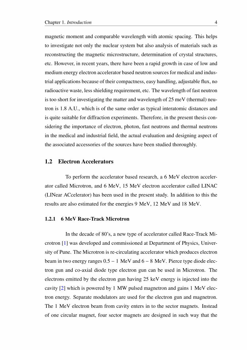
thereby gives 6 MeV electron beam. Adequate shielding provided with the help
of lead bricks and concrete blocks which can be seen in a view of the Race-Track
Microtron in Figure 1.2(a).
All the operation parameter of the Microtron such as an injection en-
ergy, radio frequency, drift space length and magnetic field in the sector electro-
magnet are adjusted in such a way that the beam can come out from the extraction
port. All these parameters are controlled and monitored from the control console
which is shown in Figure 1.2(b). The various parameters/specifications of the
Chapter 1. Introduction 6
(a) (b)
Figure 1.2: Photograph of (a) Race-Track Microtron (b) Control panel of the same.
Race-Track Microtron are shown in Table 1.1. Based on pulsed current (1 – 10
mA), pulse width (2 µ sec) and pulse rate (50 PPS) the average current of the
electron beam is varying between 0.1 µA and 1 µA.
Table 1.1: Specifications of the Pune University Race-Track Microtron.
1. Beam Particle Electrons2. Operating Beam Energy 0.5 – 1 MeV and of 6 – 8 MeV3. Beam Current (peak pulse) 1 – 10 mA4. Beam Current (average) 0.1 – 1 µA5. Number of Orbits 6 – 86. Pulse Width 1.6 – 2 µs7. Maximum Pulse Rate 50 – 100 PPS8. Oscillator Type Magnetron (MG5236)9. Operating Frequency of Magnetron 2780 MHz10. R.F.Peak Power 1 MW11. Beam Diameter Variable 1 – 6 mm (without scattering)12. Cavity type Right Circular Cylinder, TE010 mode13. Main Chamber 50.8 cm O.D × 7.6 cm high14. Operating Vacuum in the system 10−6 Torr15. Magnet Type Four Sectors16. Magnetic field Strength at gap 1370 Gauss17. Maximum Gun Voltage 25 kV18. Gun Current 120 mA
1.2.2 Linear Accelerator
Society for Applied Microwave Electronics Engineering and Research
(SAMEER), Mumbai is a research institute engaged in developing the Linear Ac-
celerator (LINAC) facilities for medical as well as industrial applications. The

Chapter 1. Introduction 7
technology to develop ‘S’ band compact side coupled standing wave electron lin-
ear accelerator is very well established at SAMEER, Mumbai center [3]. Based
on this technique 6 MeV to 15 MeV linac are developed at SAMEER, Mumbai.
In linear accelerator, the electrons are accelerated using nonconserva-
tive microwave RF fields. A Pierce’s type diode gun is used as an electron source.
Waveguides are evacuated or gas filled metallic structures of rectangular or cir-
cular cross-section. Two types of waveguide are used in linacs (a) RF power
transmission waveguides and (b) accelerating waveguides. The standing wave
structure of accelerating waveguide is used in linear accelerator of SAMEER.
A schematic diagram of standing wave accelerating waveguide is shown in Fig-
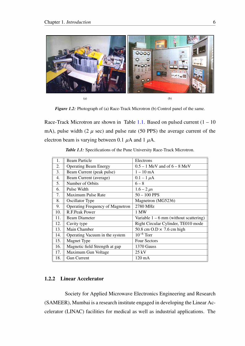
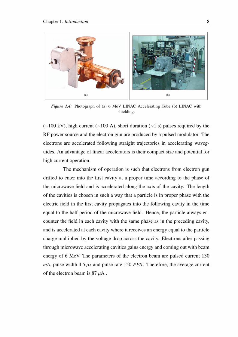
ure 1.3. Six cells are brazed together to make a 32 cm long linac tube as shown
in Figure 1.4(a) and linac with shielding is shown in Figure 1.4(b).
rf in
Electron gun
Accelerating
cavity
Coupling cavity
Figure 1.3: Schematic diagram of standing wave accelerating waveguide of 6 MeVLinear Accelerator
The linac tube has two buncher cavities and five acceleration cavi-
ties. The linac tube is water cooled to maintain the body temperature within
5°C. The electrons are accelerated in the accelerating waveguide by means of
an energy transfer from the microwave radiation produced by high power RF
fields. The microwave power produced by 2.6 MW magnetron at 2856 MHz fre-
quency is carried to the accelerating waveguide through rectangular uniform S
band waveguides that are either evacuated or more commonly pressurized with a
dielectric gas (Freon or sulfur hexafluoride, SF6) to twice the atmospheric pres-
sure. The klystron is used as high power microwave amplifier. The high voltage
Chapter 1. Introduction 8
Figure 3: SAMEER made side coupled linac tube.
(a) (b)
Figure 1.4: Photograph of (a) 6 MeV LINAC Accelerating Tube (b) LINAC withshielding.
(∼100 kV), high current (∼100 A), short duration (∼1 s) pulses required by the
RF power source and the electron gun are produced by a pulsed modulator. The
electrons are accelerated following straight trajectories in accelerating waveg-
uides. An advantage of linear accelerators is their compact size and potential for
high current operation.
The mechanism of operation is such that electrons from electron gun
drifted to enter into the first cavity at a proper time according to the phase of
the microwave field and is accelerated along the axis of the cavity. The length
of the cavities is chosen in such a way that a particle is in proper phase with the
electric field in the first cavity propagates into the following cavity in the time
equal to the half period of the microwave field. Hence, the particle always en-
counter the field in each cavity with the same phase as in the preceding cavity,
and is accelerated at each cavity where it receives an energy equal to the particle
charge multiplied by the voltage drop across the cavity. Electrons after passing
through microwave accelerating cavities gains energy and coming out with beam
energy of 6 MeV. The parameters of the electron beam are pulsed current 130
mA, pulse width 4.5 µs and pulse rate 150 PPS . Therefore, the average current
of the electron beam is 87 µA .

Chapter 1. Introduction 9
1.3 Interaction of Radiations with Matter
Each radiations behaves differently while passing through the material.
1.3.1 Electrons
In an absorbing material a electron is slowed down and finally brought
to rest by the combined action of all four of these elastic and inelastic processes.
1. Elastic collision with atomic electron
An incident charged particle may be elastically deflected in the field of the atomic
electrons of the struck atom. Energy and momentum are conserved and the en-
ergy transfer is generally less than the lowest excitation potential of the electrons,
so that the interaction is really with the atom as whole. Such collisions are sig-
nificant only for the case of very low energy (< 100 eV) incident electrons. The
cross-section for this process is,
σelectron ∝2zβ4 (barn/atom) (1.1)
θ ≥ 450
Scattered
electron
2. Elastic collision with atomic nuclei
The incident particle is elastically deflected in the field of nucleus. It loses only
the kinetic energy required for conservation of momentum. This is a radiative
free process. The deflection due to nucleus will takes place at an angle greater
than 90°. Cross-section for this process is very small and is given as
σnucleus ∝Z2
4β4 (barn/atom) (1.2)
θ ≥ 900
Scattered
electron
Chapter 1. Introduction 10
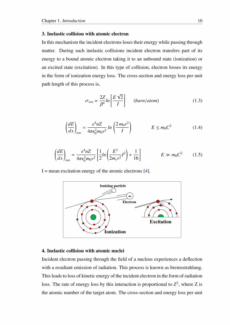
3. Inelastic collision with atomic electron
In this mechanism the incident electrons loses their energy while passing through
matter. During such inelastic collisions incident electron transfers part of its
energy to a bound atomic electron taking it to an unbound state (ionization) or
an excited state (excitation). In this type of collision, electron losses its energy
in the form of ionization energy loss. The cross-section and energy loss per unit
path length of this process is,
σion ∝2Zβ4 ln
E√
2I
(barn/atom) (1.3)
(dEdx
)ion
=e4nZ
4πε20m0v2
ln(2 m0v2
I
)E ≤ m0C2 (1.4)
(dEdx
)ion
=e4nZ
4πε20m0v2
[12
ln(
E3
2mev2 I2)
+1
16
]E � m0C2 (1.5)
I = mean excitation energy of the atomic electrons [4].
Ionization
Electron
Ionizing particle
Excitation
4. Inelastic collision with atomic nuclei
Incident electron passing through the field of a nucleus experiences a deflection
with a resultant emission of radiation. This process is known as bremsstrahlung.
This leads to loss of kinetic energy of the incident electron in the form of radiation
loss. The rate of energy loss by this interaction is proportional to Z2, where Z is
the atomic number of the target atom. The cross-section and energy loss per unit

Chapter 1. Introduction 11
path length of this process is, [4]
σrad = 4(ln
[2(E + m0C2)
m0C2
]−
13
)σ0Z2 (barn/atom) (1.6)
(dEdx
)rad∝
Z2nA
(E + m0 C2
)(1.7)
+Ze
Bremsstrahlung
radiation
Bremsstrahlung
radiation
Incident Electron
Inelastically
scattered Electron
The collisional energy loss is predominant for light elements and at low
electron energies while radiative losses start becoming comparable only at high
electron energies and for heavy targets. When a charged particle is either accel-
erated or decelerated in an electric field, electromagnetic radiations may be given
off. If an electron passes close to nucleus while traversing a substance, the charge
Z on the nucleus will exert a force on the electron. This will cause its path to be
bent. During this acceleration, the electron may radiate energy of any amount
from zero up to its total kinetic energy (Ek) in the form of bremsstrahlung. The
total bremsstrahlung per atom is roughly proportional to (Z/m)2, where Z is the
atomic number of the absorbing matter and m is the mass of the charged particle.
Because of a 1/m2 dependence, the amount of bremsstrahlung is almost com-
pletely negligible for all particles except electrons, unless the particle energy is
in the GeV range.
As a electron traverses matter, it suffers many ”soft” or ”glancing” col-
lisions with the atoms along its path. At each collision the particle loses energy

Chapter 1. Introduction 12
and changes its direction slightly. The net result is that the electrons path is
very tortuous. The Range of the particle(R) (gm/cm2) is defined as the mini-
mum thickness required of an absorber to stop the particle (electron). The small
variations in the range is called Straggling of the particle. This is the statisti-
cal fluctuations. The Radiation Length(L) (gm/cm2) is the absorber thickness
needed to reduce the electron energy by radiation loss to 1/e of its original value.
The energy loss per unit path length is known as Specific Energy Loss (dE/dx)
(MeV−cm). The Stopping Power(S) (MeV−cm2/gm) is defined as the average
value of specific energy loss of the particle in a given absorber. The Stopping
Cross section(ε) (MeV−cm2/atom) is defined as the average energy loss per
atom of given absorber for electron.
1.3.2 Photons
Different interactions dominate for different photon energies. The main
modes of interaction of gamma rays with matter are the photo effect both in its
photoelectric and photonuclear forms, Compton scattering and electron positron
pair production. To a minor extent photofission, Rayleigh scattering and Thom-
son scattering also occur.
1. Photoelectric effect:
In this process, the photon is absorbed by an atom and expels an electron by los-
ing all its energy in one interaction. The probability of photoelectric absorption
is inversely proportional to the gamma photon energy and proportional to atomic
number of the atom (Z5). The probability is greater the more tightly the electron.
The kinetic energy Ee of the emitted photo electron is given by (hν − Eγ) [5].
σphotoelectric ∝ Const.Z5
E3.5 (barn/atom)
(1.8)Photo-
electron
Incident gamma
E
Ee
Atom

Chapter 1. Introduction 13
2. Compton scattering:
In this process, the gamma ray interacts with a free or weakly bound electron
and transfers part of its energy to electron. The photon is scattered through an
angle θ with an energy E′ while the electron recoils with kinetic energy (Ee) at
an angle φ. The kinetic energy of the electron is equal to the difference of the
energy lost by the gamma ray and the electron binding energy. Ee = hν − E′.
The probability for this process is weakly dependent on E and Z. The interaction
probability depends on the electron density, which is proportional to Z/A and
nearly constant for all materials.
σc ∼πr2
0Z2Eγ
[ln
(4Eγ +
12
)](barn/atom)
(1.9)
Eγ = MeV, r0 = Classical electron ra-
dius.
Scattered
gamma
Atomic
electron
Free or weekly
bound electron
Incident gamma
E =h
3. Pair production:
In this process, the gamma ray losses all its energy in one interaction. A gamma
ray with an energy of at least 1.022 MeV can create an electron-positron pair
when it is under the influence of the strong electromagnetic field in the vicinity
of a nucleus. A photon cannot create an electron-positron pair in free space, as
the process cannot conserve momentum and energy. In this interaction the nu-
cleus receives a very small amount of recoil energy to conserve momentum, but
the nucleus is otherwise unchanged and the gamma ray disappears. A heavier
nucleus takes less recoil energy. This interaction has a threshold of 1.022 MeV
because that is the minimum energy required to create the electron and positron.
If the gamma ray energy exceeds 1.022 MeV, the excess energy is shared between
the electron and positron as kinetic energy. Above the threshold, the probability
of the interaction increases rapidly with energy. The probability of pair produc-
tion is proportional to the square of the atomic number Z and is significant in
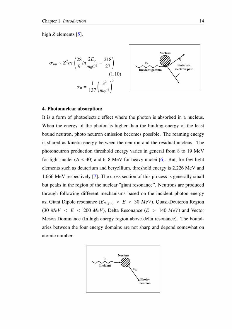
Chapter 1. Introduction 14
high Z elements [5].
σpp ∼ Z2σ0
(289
ln2Eγ
m0C2 −21827
)(1.10)
σ0 =1
137
(e2
m0c2
)2
Incident gamma
EPositron-
electron pair
Nucleus
4. Photonuclear absorption:
It is a form of photoelectric effect where the photon is absorbed in a nucleus.
When the energy of the photon is higher than the binding energy of the least
bound neutron, photo neutron emission becomes possible. The reaming energy
is shared as kinetic energy between the neutron and the residual nucleus. The
photoneutron production threshold energy varies in general from 8 to 19 MeV
for light nuclei (A < 40) and 6–8 MeV for heavy nuclei [6]. But, for few light
elements such as deuterium and beryzllium, threshold energy is 2.226 MeV and
1.666 MeV respectively [7]. The cross section of this process is generally small
but peaks in the region of the nuclear ”giant resonance”. Neutrons are produced
through following different mechanisms based on the incident photon energy
as, Giant Dipole resonance (Eth(γ,n) < E < 30 MeV), Quasi-Deuteron Region
(30 MeV < E < 200 MeV), Delta Resonance (E > 140 MeV) and Vector
Meson Dominance (In high energy region above delta resonance). The bound-
aries between the four energy domains are not sharp and depend somewhat on
atomic number.
Photo-
neutron
Incident
E
En
Nucleus

Chapter 1. Introduction 15
1.3.3 Neutrons
The interaction process of neutrons with matter are fundamentally dif-
ferent from the interactions of photons. Neutrons interact with nuclei through the
strong force and are non-ionizing. Because the neutron has no charge, it will not
be scattered by the light electron clouds surrounding the nucleus, but will travel
straight on to nucleus. Neutrons cross sections not only can vary rapidly with the
incident neutron energy, but they vary erratically from one element to another
and even between isotopes of the same element. Neutrons while passing through
matter interacts by five different processes. The particular effect which occurs
depends upon the properties of the substances and the energy of the neutron. In
the first two, known as scattering reactions, a neutron elastically and inelastically
emerges from the reaction. In the remaining reactions, known as absorption reac-
tions, the neutron is absorbed into the nucleus and something different radiation
emerges.
1. Elastic scattering (n, n):
Before
Collision
After
Collision
Recoil
Nucleus
Neutron
Neutron
If the kinetic energy of the incident neutron is insufficient to excite the lowest
level of the nucleus, the neutron is emitted with approximately the same kinetic
energy which it had when it entered the nucleus. Hence this process is called
elastic scattering. For fast and intermediate neutrons, elastic scattering is the
dominant mode of interaction. This is the most important process for slowing
down of neutrons. Light nuclei are the most effective for slowing neutrons. A
neutron colliding with a heavy nucleus rebounds with little loss of speed and

Chapter 1. Introduction 16
transfers very little energy. Total kinetic energy is conserved in this process and
the energy lost by the neutron is transferred to the recoiling particle. If the col-
lision of neutron and nucleus is head on, maximum energy transfer occurs. The
cross section for this process is depend on energy and material.
2. Inelastic scattering (n, n′γ):
A neutron may strike a nucleus and be temporarily absorbed, forming a com-
pound nucleus. This will be in an excited state. It may de-excite by emitting
another neutron of lower energy, together with a gamma photon, which takes the
remaining energy. This process is called inelastic scattering. In the inelastic scat-
tering process the scattering nuclei are left in an excited state which decay by the
emission of gamma rays. It generally happens only when high energy neutrons
(E > 1 MeV) interact with heavy nuclei. Heavy nuclides have lower threshold
than light nuclides.
Before
Collision
After
Collision
Recoil
Gamma
NucleusNeutron
Neutron
(b)
3. Nonelastic scattering (n, γ), (n, α), (n, p):
Lower Z
NucleusNucleus
NeutronProton
Before collision After collision (e)
Nucleus
Neutron
Alpha
Lower Z
Nucleus

Chapter 1. Introduction 17
Differs from inelastic scattering in that a secondary particle emitted is not a neu-
tron. A nucleus may absorb a neutron forming a compound nucleus, which then
de-energizes by emitting a charged particle, either a proton or an alpha particle.
This produces a nucleus of a different element. Such a reaction is called a trans-
mutation. Transmutation is the transformation of one element into another by a
nuclear reaction. Such reactions are generally threshold reactions.
4. Radiative Capture (n, γ):
Same as nonelastic scatter, but by definition, neutron capture occurs only at low
neutron energies (thermal energy range is < 0.025 eV). The compound nucleus
resulting from the capture of neutron has a high energy of excitation. Capture
leads to the disappearance of the neutron. The de-excitation of the compound
nucleus is accomplished by the emission of gamma rays and the reaction in con-
sequence is known as radiative capture. The production of radioactive nuclide by
radiative capture is a consequence of the fact that the prompt emission of gamma
rays does not usually remove all of the excitation energy leaving the product nu-
cleus unstable. The excess energy is then dissipated by the familiar processes
known collectively as radioactivity. This is the dominant process for thermal
neutron.
GammaNucleus
(mass A) Neutron
Nucleus (mass
A+1 (in excited
state)
(c)
Before
collision
After
collision
5. Fission / Spallation (n, f ):
Probably the most spectacular effect produced by neutrons when captured in nu-
clei is nuclear fission. Nuclear fission is a phenomenon in which a heavy nucleus,
splits into two smaller nuclei, called fission fragments, mostly one often nearly
half the mass as the other, and rarely of equal masses. This reaction gives off a
large amount of energy and emits two or more neutrons, and gamma rays. When

Chapter 1. Introduction 18
a neutron hits a heavy nuclide like U-235, the neutron gets absorbed in the heavy
nuclide that gets energetically agitated (or excited). If the new energy state of
the heavy nuclide is sufficient for it to split, then it can split to cause fission. The
neutrons produced in fission are fast, with an average energy of 2 MeV. This pro-
cess is important at neutron energies in excess on 100 MeV. (cross sections are
higher at 400-500 MeV). Material like Uranium, can cause a nucleus to undergo
fission.
(d)
NucleusNeutron
Fragments
After
collisionBefore
collisionA+1 (in excited
1.4 Monte Carlo Based FLUKA Simulation
The radiation field of electron accelerator includes several components
such as bremsstrahlung photons, fast neutrons, positrons, hadrons and muons.
The production and transport of all these radiations through different targets are
difficult to study theoretically even on the basis of correct experiments. There-
fore, simulations with an effective Monte Carlo code are very helpful to get in-
formation of all the particles produced in accelerator head and for the formation
of accelerator based neutron source. A general purpose Monte Carlo based code
FLUKA [8] has been used for the calculations of particle transport and interac-
tions with matter. FLUKA code version 2006 and 2008 has been used to calculate
the results published in this thesis. It can simulate of about 60 different particles
with high accuracy, including photons, electrons, neutrons, heavy ions and an-
tiparticles. The program can also consider polarized photons (e.g., synchrotron
radiation) and optical photons. The lowest transport limit for all particles is ∼1
keV. There are various tools for input geometry visualization and output plotting
in two and three dimensions giving a clear picture of the calculations. FLUKA

Chapter 1. Introduction 19
can handle very complex geometries, using an improved version of the well-
known Combinatorial Geometry (CG) package.
1.4.1 Transport
FLUKA uses an original transport algorithm for charged particles, in-
cluding complete multiple Coulomb scattering treatment. It also uses Bethe-
Bloch theory for energy loss mechanism. Delta-ray production via Bhabha and
Moller scattering is implemented in FLUKA. The differences between positrons
and electrons are taken into account in both stopping power and bremsstrahlung
case. For photons; pair production, Compton effect, Photoelectric effect, pho-
tonuclear reactions with cross sections for all the elements, emission of fluores-
cence photons and photon polarization for Compton, Rayleigh and Photoelectric
effects are some of the important features implemented. Low energy neutrons are
handled in 260 groups with varying group structure prepared from ENDF, JEF
and JENDL evaluations. This technique results in faster calculations as compared
to using point wise cross sections.
1.4.2 Cross sections
In FLUKA the full set of Seltzer and Berger cross sections [9] of ac-
curate electron-nucleus and electron-electron bremsstrahlung has been tabulated
in an extended form [10]. There are significant improvements on the treatments
of photonuclear reaction in FLUKA with time [11–13]. The Fasso A. et al. [13]
explains in details about the materials for which the photonuclear reactions cross
sections are included in FLUKA. The photo nuclear interactions are modeled by
Vector Meson Dominance, Delta Resonance, Quasi-Deuteron and Giant Dipole
Resonance model over the whole energy range [14]. The photonuclear reactions
have been successfully benchmarked with activation and neutron spectrometry
experiments.

Chapter 1. Introduction 20
1.4.3 Scoring
The FLUKA code has numerous options to score the required quantity
and has been designed with accelerator applications in mind. The double differ-
ential cross sections and yields, region and density independent scoring of en-
ergy deposition, residual nuclei formation are some of the features generally not
available in other Monte Carlo codes. In addition to these, track length estima-
tor, boundary crossing estimator, collision estimator, event by event information,
radioactive decay, etc, are also possible. FLUKA scores fluence and current as
a function of energy and angle. It can also score track-length fluence in a bin-
ning structure (cartesian or cylindrical) independent of geometry. The fluence
and current are two different quantities, for surface crossing estimator current
calculated as the number of particle crossing the surface per unit area while flu-
ence calculates the average surface fluence by adding dt/cosθ for each particle
crossing the surface. For parallel beam, current and fluence are same while for
isotropic distribution current is half of fluence.
1.4.4 Biasing
The FLUKA code can be run in fully analogue or biased mode. In ad-
dition to the usual biasing such as splitting, Russian Roulette, few unique tech-
niques such as biasing the interaction length to statistically enhance the produc-
tion of secondaries that have low production cross section, biased decay length
for increased daughter production etc are also implemented. Sufficient number
of primary electrons have been traced in the simulation and the resultant statis-
tical uncertainties of the Monte Carlo results were in the levels of about 1% for
bremsstrahlung and 5% for induced photoneutrons, respectively.
1.4.5 Input
FLUKA reads user input from an ASCII ‘standard input’ file with ex-
tension .inp, which is in particular format. Typically, an input file begins with a

Chapter 1. Introduction 21
TITLE card. All ‘events’ or ‘histories’ are initiated by primary particles, there-
fore a card defining primary particle and its related information is added. The
main part of the input is the geometry of the problem. By defining the bodies
and boolean operations of subtraction (or complement), intersection and union
on these bodies different regions can be formed. The materials defined in the
input or predefined materials are used to fill the regions. The production, cut
off and transport threshold energies for particles are provided. The detectors are
defined in geometry wherever detection has to be done. With the help of avail-
able detector cards detection of the particle can be done for various regions. The
physical quantity such as dose, fluence, current etc. are detected. To calculate the
statistical error of the results, it is necessary to perform other independent runs,
each with different initialization. For this random number sequence is input to
FLUKA. The completed input file is run with the help of FLUKA executable.
The output of the run provides separate file for each detector which has been
used in input file. The output file is in unformatted format, which has to convert
in formated form by using codes provided in FLUKA for getting data.
1.5 Radiation units used in FLUKA and experiments
1. Flux (particles−cm−2−sec−1): Flux is a term referring to the number of
particles passing through an area over a span of time.
2. Particle Fluence (Φ) (particles−MeV−1−cm−2 per primary particle): The
particle fluence is defined as the particle flux integrated over a certain time
period and represents the number of particles per unit area that passed dur-
ing this time.
3. Particle Current (J) (particles−MeV−1−cm−2 per primary particle): The
particle current is defined as the number of particles crossing an area over a
certain time period and represents the number of particles per unit area that
passed during this time.

Chapter 1. Introduction 22
Fluence and Current:
Fluence and Current are two separate quantities which are used
in FLUKA simulation for surface crossing estimation. Imagine a surface
having an infinitesimal thickness dt. A particle incident with an angle θ
with respect to the normal of the surface S will travel a segment dt/cosθ.
Therefore, we can calculate an average surface fluence by adding dt/cosθ
for each particle crossing the surface, and diving by the volume S .dt, while
the current J will be to count the number of particles crossing the surface
divided by the surface area
Φ = limdt→0
∑i
dtcosθi
S .dtJ =
dNdS
(1.11)
The fluence is independent from the orientation of surface S , while the
current is NOT! In an isotropic field it can be easily seen that on a flat
surface J = Φ/2.
4. Yield (particles−sec−1 per primary particle): The total particle coming out
from the system per unit time. The particles are measured over a cross
sectional area.
5. Dose (J/kg, GeV/g, RAD, Gray): It is the amount of energy deposited in a
medium by ionizing radiation. It is equal to the energy deposited per unit
mass of medium.
6. Dose Equivalent (Sievert(Sv), Roentgen Equivalent Man(REM)): The equiv-
alent dose (HT ) is a measure of the radiation dose in tissue. Equivalent dose
(HT ) is calculated by multiplying the absorbed dose to the organ or tissue
(DT ) with the radiation weighting factor, (wR).

Chapter 1. Introduction 23
7. Isocenter: The radiation isocenter (in contrast to the mechanical isocenter)
is the point in space where radiation beams intersect when the Gantry is
rotated during beam-on. The placement of the radiation isocenter plays an
important role in treatment planning because ideally the isocenter should
be placed in the center of the target volume, usually a tumor.
1.6 Outline of the Thesis
The thesis is divided into seven chapters.
The first chapter is on ”Introduction” is discussed already.
The Chapter second which is on “Design of dual scattering foil for
6 to 20 MeV electron beam Radiotherapy” begins with a literature survey on
scattering foil design for electron radiotherapy. The electron beam from the lin-
ear accelerator is of size ~2 mm, whereas the size of the electron beam profile
required for actual treatment is usually larger than 2 × 2 cm2 up to 30 × 30 cm2
at the iso-center. Therefore, scattering foils were optimized through two differ-
ent ways (i) by analytical calculations and (ii) by simulations with FLUKA code.
The objective of this chapter is to discuss the designing of the dual scattering foil
for 6 to 20 MeV electron beam.
In the present work, it is proposed to use a system with two scatter-
ing foils. The first foil called the primary foil which is made of high Z ele-
ment such as gold, tungsten, tantalum, etc., whereas, the secondary foil is made
of low Z element such as Aluminum. Electrons while passing through high Z
medium undergo multiple coulomb scattering and therefore, the pencil beam is
converted into Gaussian shape. The primary scattering foil was kept to be uni-
form thickness, whereas the secondary foil was of Gaussian shape with varying
thickness; maximum at the center and minimum at the edges. Electrons falling at
and around the centroid have experienced maximum scattering events, whereas
those falling at the tail of the profile have experienced the minimum scattering
events. The Gaussian width and thickness of the secondary foil were optimized
such that it should meet the design parameters (Dose at iso-center, beam unifor-
mity, etc.). As a result, the profile of the electron beam is reasonably flat over the

Chapter 1. Introduction 24
designated field area of 30 × 30 cm2, with sharp fall off at the edges of the field.
The thickness and shape of the foils were calculated using FLUKA code as well
as through analytical calculations. The simulated results obtained from both the
ways were compared, and they are in good agreement.
The third chapter which is on “Characterization of bremsstrahlung
radiations for 6 to 18 MeV electron beam from different Z elements: exper-
imental and simulation approach” mainly deals with the study of the exact
analysis of bremsstrahlung spectra for different e− γ targets. When high energy
electrons pass through a target, it generates a cascade shower of bremsstrahlung
radiation with continuous energy spectrum shows an end point equal to the elec-
tron kinetic energy. A study of bremsstrahlung spectra from 6 – 18 MeV electron
beam were carried out using FLUKA. The study includes different material as
bremsstrahlung producing targets ranging from low to high Z elements. The ma-
terials are Beryllium, Aluminum, Silicon, Copper, Iron, Molybdenum, Silver,
Gadolinium, Bismuth, Tungsten, Tantalum, Lead, Gold, and Uranium. The ma-
terials which having higher melting point were selected for e− γ target because
when an electron interacts with material, it generates a high amount of heat,
which rises the temperature of the target. Bremsstrahlung spectra were estimated
at various angles at different target thickness from thin target to the thickness up
to range of the target. The requirement of gamma therapy also requires less con-
tribution of other radiations. Therefore, the contribution of other radiations such
as electrons, positrons and neutrons were calculated for each case and reported
in the thesis. Moreover, the depth dose curve was estimated in water phantom
(equivalent to the human body) at 100 cm Source to Surface Distance (SSD) to
get an exact idea of dose delivered to the patient body.
It has been observed from the results of bremsstrahlung spectra that
initially there is increase in the bremsstrahlung fluence [(photon−cm−2)/e−] with
target thickness up to certain thickness and further increase in thickness de-
creases the fluence due to absorption of photons in the material itself. The thick-
ness giving maximum bremsstrahlung fluence is different for different material.
From the angular distribution of bremsstrahlung, it is observed that the maximum

Chapter 1. Introduction 25
bremsstrahlung fluence is in the forward direction (0°). Also, average energy of
bremsstrahlung radiation is higher in the forward direction. Moreover, it is also
observed that the bremsstrahlung yield (photon/e−) increases with the increase
in incident electron energy. The tungsten found to be good candidate which gives
maximum bremsstrahlung fluence. This data will help researchers and medical
physicists to take precise right hand data of flux and energies of bremsstrahlung
radiations to be used for desire object in radiation therapy.
The experimental results published by D. W. O. Rogers were simu-
lated in FLUKA for the verification of code and subsequently compared. In
another case, an experiment performed by Bhoraskar, et al. on measurement of
bremsstrahlung spectra from tantalum using 6 MeV Race-Track Microtron was
also simulated. In both the cases the simulated results obtained by FLUKA are
in good agreement with their experimental results.
The fourth chapter which is on“Estimation of Neutron Production
from Accelerator Head Assembly of 15 MV Medical LINAC using FLUKA
Simulations” mainly deals with the estimation of neutron contamination in a
bremsstrahlung beam from optimized accelerator head assembly of 15 MV med-
ical LINAC. The accelerator operating above 10 MeV can result in the production
of neutrons, mainly due to photo nuclear reaction (γ, n) induced by high energy
photons in the accelerator head materials. These neutrons contaminate the thera-
peutic beam and give a non negligible contribution to patient dose.
For production of a clinical photon beam, the design of accelerator head
assembly was optimized using 15 MeV electrons. The accelerator head assembly
consists of two different collimators. The first one is the primary collimator. The
second one is an adjustable rectangular secondary collimator which consists of
two upper and two lower independent jaws for producing rectangular and square
fields with a maximum dimension of 40 × 40 cm2 at the linac iso-center. For
this purpose high Z materials were simulated for primary collimator. The gamma
while passing through such collimators generates neutrons through photo nuclear
reaction. The collimators were optimized such that the neutron contamination in
the gamma beam was below the allowed limit.

Chapter 1. Introduction 26
The e− γ target, primary and secondary collimator, were designed in
Monte Carlo based FLUKA code and the corresponding neutron dose equiva-
lent and gamma dose at the patient plane (in water phantom at 100 cm from
e− γ target) were estimated. Results were obtained at various field sizes varying
from 0 × 0 cm2, 10 × 10 cm2, 20 × 20 cm2, 30 × 30 cm2, 40 × 40 cm2. The
maximum neutron dose equivalent observed near the central axis of 30 × 30 cm2
field and has a value 36.6 mSv/min. This is 0.61% of the central axis photon
dose rate of 60 Gy/min. The values fall within the allowed limit by International
Electrotechnical Commission (IEC). The dimensions of the collimators and fil-
ters were optimized in such a way that the neutron dose equivalent estimated is
below the allowed limit in the therapy beam.
The Fifth chapter which is on “Measurement of angular distribu-
tion of neutron flux for the 6 MeV Race-Track Microtron accelerator based
pulsed neutron source” includes the detail discussion about the experimental
and simulation results. This source is having applications in an elemental analy-
sis by Delayed Gamma Neutron Activation Analysis (DGNAA) and analysis of
short lived activation products. In addition to this, an attempt has been made to
use this source for studying the (n, α) reaction. Bremsstrahlung radiation pro-
duced through e− γ target can be redirected towards a suitable γ− n target and
produce neutron through photo nuclear reaction. The photo neutron production
threshold energy varies in general from 8 – 19 MeV for light nuclei (A < 40) and
6 – 8 MeV for heavy nuclei. But, for few light elements such as deuterium and
beryllium, threshold energy is 2.226 MeV and 1.666 MeV respectively. These
targets are suitable for generating neutrons as far as low energy of the electron
beam is concerned. Therefore, beryllium was chosen as the γ− n target.
It was observed from the FLUKA simulations that the total neutron flu-
ence is found to be more in cylindrical geometry in comparison to parallelepiped
geometry. Therefore, for further studies cylindrical geometry of the target was
chosen and the respective thickness was varied. It was also observed that as the
target thickness increases, neutron yield increases and saturates beyond the thick-
ness of 4 cm. Using the optimized target, the maximum neutron flux and neutron

Chapter 1. Introduction 27
yield one can obtain from the Microtron is 1.2319 ×10⁶ neutron−cm−2−sec−1 and
4.064 ×10⁸, neutron−sec−1 respectively for 1 µA current of the electron beam.
Integrated neutron flux was also measured experimentally by activation of vana-
dium at 0°, 30°, 60°, 90°, 115°, and 140°angles and subsequently compared with
the simulated one. The neutron flux was found to be decreased with the increase
in angle. The decreasing trend in neutron flux has been observed in the case
of simulated results by FLUKA. Our experimental results show good agreement
with the simulated results by FLUKA.
The Chapter sixth which is on “Optimization of thermal neutron
source based on 6 MeV Linear Accelerator using FLUKA simulation” deals
with design of 6 MeV Linear Accelerator based thermal neutron source for ele-
mental analysis. Neutrons produced through photo nuclear reaction in γ− n target
mainly belongs to high energy range. Therefore, reduction in neutron energies
from fast to thermal is possible by neutron interaction with set of low Z materi-
als. Neutrons while passing through a material the flux decreases due to neutron
capture, neutron escape and inverse square law Φ(r) ~ (1/r2). When designing
such thermal neutron source, the challenges were made to bring down the neu-
tron energies to thermal by keeping the neutron economy. In addition, gamma
production at the output is to be maintained very low. In design of thermal neu-
tron source, the materials and dimensions of each region were determined using
Monte Carlo based FLUKA code. The optimized materials in different regions
are Beryllium as a γ− n target, polyethylene as a filter, alumina as a reflector and
graphite + polyethylene as a moderator using FLUKA.
A prototype experiment was carried out using 6 MeV linac and the
integrated neutron flux was measured with activation technique. For the mea-
surement of total (fast + thermal) neutron flux and thermal neutron flux, the
vanadium and cadmium covered vanadium was used. To obtain the effective
thermal neutron flux, the flux measured by cadmium covered vanadium sample
was subtracted from the flux measured by vanadium sample. The total neutron
flux and thermal neutron flux were measured at various target thickness of wax
material (moderator) from 0 to 16 cm along forward (0°), perpendicular (90°)
Chapter 1. Introduction 28
and backward direction (180°) with respect to the incident gamma. The total
neutron flux decreases and thermal neutron flux increases up to 4 cm thickness
of wax. Further, increase in the wax thickness the contribution of thermal neutron
increases. Our experimental results show good agreement with the simulated re-
sults by FLUKA.
The chapter seventh which is on “Design and Development of 15
MeV Linear Accelerator based Neutron Radiography facility” mainly deals
with the work on design and development of Neutron Radiography facility. Based
on the same technique as discussed in chapter sixth, optimization of the thermal
neutron facility was carried out for 15 MeV linear accelerator. The major part
of the design was to optimize the collimator for neutron beam. The main design
parameters for the collimator are collimation ratio, gamma content, neuron flux,
cadmium ratio, beam uniformity, etc.
The simulation results on the collimator design show that as an increase
in collimation ratio (L/D) the image sharpness of radiograph increases due to
less scattered neutron beam, but subsequently the neutron flux at the object plane
decreases. The collimator was designed with cadmium lining square cone to
capture the scattered thermal neutrons. For this purpose, the collimation ratio
was optimized L/D=18 and the simulations were carried out to optimize the rest
parameters. The gamma contamination in the beam influences the quality of
generated neutron radiographs. Therefore, in the simulation a care was taken to
minimize the neuron to gamma ratio. The neutron flux of the optimized facility
obtained at the object plane is 1 ×10⁵ n−cm−2−sec−1 and neutron to gamma ratio
is 1 ×10⁵ n−cm−2−mR−1.
Moreover, some of the radiographs have also been taken up using the
radiography facility of APSARA reactor at BARC, Mumbai for right hand ex-
perience and understanding. The samples are aluminum plates filled with boron
and lithium chloride, different Z materials having the same thickness, electronic
components (MOSFET and IC’s), etc. In addition, some radiographs were also
obtained for a silver key chain and plant. All the radiographs were taken by direct
techniques using 25 mm Gadolinium screen and D–7 type industrial X-ray film.

Bibliography
[1] Bhoraskar, V.N., 1988. The Microtron: A recirculating electron accelerator. Indian J.Phys., 62A(7), 716.
[2] Asgekar, V.B. et al., 1980. Single cavity 8 MeV race track microtron. Pramana 15(5),479–493.
[3] Krishnan, R. et al., 2007. S band LINAC tube development work in SAMEER. Proceed-ings of PAC09, Vancouver, BC, Canada.
[4] Singru, R.M., Introduction to experimental nuclear physics. Wiley estern Pvt. Ltd.
[5] Davisson, C.M., 1965. Interaction of gamma radiation with mater. pp37–78.
[6] Loi, G. et al., 2006. Neutron production from a mobile linear accelerator operating inelectron mode for intraoperative radiation therapy. Phys. Med. Biol., 51, 695–702.
[7] Mobley, R. C. Laubenstein, R. A., 1950. Photoneutron thresholds of beryllium and deu-terium. Phys. Rev., 80(3), 309.
[8] Fasso, A. et al., 2005. FLUKA: a multi-particle transport code. CERN-2005-10,INFN/TC-05/11, SLAC-R-773.
[9] Seltzer, S.M. Berger, M.J., 1986. At. Data Nucl. Data Tab., 35, 345 .
[10] Fasso, A. et al., 1995. FLUKA: Performance and applications in the intermediate energyrange. OECD documents, 287–304.
[11] Fasso, A. et al., 1995. Designing of electron accelerator shielding with FLUKA. CERNinternal report TIS-RP/IR/95-27, 643–649.
[12] Fasso, A. et al., 1998. Total giant resonance photonuclear cross sections for light nuclei:a database for the FLUKA Monte Carlo transport code. OECD-NEA, 61–74.
[13] Fasso, A. et al., 2005. Photonuclear reactions in FLUKA: cross sections and interactionmodels. AIP conf. Proc. 769, 1303–1306.
[14] Ranft, J. Nelson, W.R., 1987. Hadron cascades induced by electron and photon beamsin the GeV energy range. Nuclear Instruments and Methods in Physics Research SectionA, 257, 177–184.
29