study of axisymmetric nature in 3-d swirling flow in a
TRANSCRIPT

Journal of Thermal Engineering, Vol. 3, No. 6, Special Issue 6, pp. 1588-1606, December, 2017 Yildiz Technical University Press, Istanbul, Turkey
This paper was recommended for publication in revised form by Regional Editor Sandip Kale 1(Phd,IIT kgp),Assistant professor(SG),Mechanical Engineering Department, JUET, Guna, MP,INDIA
2Professor, Aerospace Engineering Department, Indian Institute Of Technology, Kharagpur, West Bengal, India, Manuscript Received 18 October 2016, Accepted 6 June 2017 *E-mail address: [email protected]
STUDY OF AXISYMMETRIC NATURE IN 3-D SWIRLING FLOW IN A CYLINDRICAL ANNULUS WITH A TOP ROTATING LID UNDER THE INFLUENCE
OF AXIAL TEMPERATURE GRADIENT OR AXIAL MAGNETIC FIELD
S. C. Dash1*, N. Singh2
ABSTRACT
The three dimensional swirling flow has been obtained by solving Navier Stokes equations, expressed in
cylindrical coordinate system, using finite difference technique on a staggered grid. An explicit finite difference
method using pressure correction technique, for the solution of Navier-Stokes has been implemented to solve
three dimensional flows. Present study explores the 3-D axisymmetric nature of stratified swirling flow and
vortex breakdown in a cylindrical annulus cavity with top rotating lid. The annulus is obtained by inserting a thin
coaxial rod in cylindrical cavity. This rod may be stationary or rotating depending on the particular study. Three
dimensional swirling flows in annuli have also been studied subjected to axial temperature gradient or under the
influence of axial magnetic field. Influence of governing parameters Re, Ri and Ha on the overall heat transfer
has been investigated through variation of the average Nusselt number with these parameters. Further, the
present numerical results are shown to be in good agreement with the available benchmark solutions under the
limiting conditions.
Keywords: Three Dimensional, Swirling Flows, Magneto Hydrodynamics, Stratified Flow, Incompressible Fluid.
INTRODUCTION
There has been interest to study swirling flow for last many decades. The swirling flow occurs in
various flow devices: ranging from centrifuges used for particle separation and collection to vortex tubes used
for cooling to furnaces and combustion chambers. Flow with swirl occurs in draft tubes of hydraulic turbines, as
well as in the casing of the compressors and axial turbines. Practical application of study of swirling flow and
vortex breakdown also ranges from vortex control on modern aircraft to mixing in combustion chambers and to
chemical reactions. In another application strong magnetic field can be used in lithium-lead alloys cooling
system of fusion reactor. This application can be realized by creating a liquid metal flow in a closed cylindrical
cavity by rotating end wall under the influence a strong axial magnetic field.
Several investigators have focused on the issue of the axial symmetry or lack of it in the lid driven
swirling flow-field. Experiments conducted by Escuder[1] indicate a small degree of asymmetry in the flow field
but did not addressed this aspect adequately. Hourigan et al. [2] argued that the asymmetry seen in the
experimental results, Escuder[1], is perhaps due to some unidentified errors remained in the observation
techniques. However, more accurate flow visualization photographs, Steven et al.[3]; Fujimura et al.[4] ; Spohn
et al.[5], too have revealed such asymmetric behavior in the swirling flow field.
As an outcome of these experimental observations it has been claimed that the vortex breakdown could
be physically an asymmetric phenomenon and hence argued that previous 2-D axisymmetric simulations are
unable to capture the 3-D asymmetric flow features. In some of the studies, Blackburn & Lopez[6]; Sotiropoulos
& Ventikos[7]; Sotiropoulos et al.[8]; Gelfgat et. al.[9]; Serre & Bontoux[10], numerical simulations of the
swirling flow have included a fully 3-dimensional model. The 3D simulations by Sotiropoulos & Ventikos[7],
reconfirmed the observation of Spohn et al.[5]that the boundary layer separation along the sidewall is basically
asymmetric and concluded that the dynamics of the vortex breakdown bubble is indeed a 3-D,asymmetric and
unsteady phenomenon.
Escudier [1] observed the vortex breakdown phenomenon in swirling flows in a cylindrical container
with a rotating lid utilizing a laser-induced-fluorescence technique. Escudier’s experimental results are the
extension of those obtained earlier by Vogel[8]and Ronnenberg [9]. One of the major contributions of his study
was to observe and report that multiple vortex breakdown bubbles can exist in the closed cylindrical geometry.
These recirculation vortex breakdown bubbles were observed to be axisymmetric and steady over a large range
of the governing parameters i.e. aspect ratio (AR) and Reynolds Number (Re).

Journal of Thermal Engineering, Research Article, Vol. 3, No. 6, Special Issue 6, pp. 1588-1606, December, 2017
1589
This study by Escudier[1] reinforced the view that the vortex breakdown in general is inherently
axisymmetric and its departures from axial symmetry is due to instabilities which are not directly associated with
the breakdown process earlier put forward by Escudier & Keller[10] . Lopez[11] carried out a detailed numerical
study with an aim to develop a more detailed understanding of the physics of the flow and to clarify features that
were not readily resolved from the visualizations. Similar to Lugt and Abboud [12], Lopez[11] too assumed an
axisymmetric flow-model and solved the Navier Stokes equations using stream-function vorticity formulation
but his solution procedure is quite different. Lopez[11] compared his numerical solutions in detail with available
experimental results, particularly dye-streak photographs of the flow due to Escuder[1] and the extent of the
agreement had been critically examined and is found to be very good. For axisymmetric case Bessai et al. [13]
have numerical studied the steady laminar magneto hydrodynamic (MHD) flow driven by rotating disk at the top
of a cylinder filled with liquid metal. Bessaı¨h et al. [14] extended this study. Gelfgat and Gelfgat [15] have
undertaken experimental and numerical study of the flow in cylindrical enclosure driven by rotating Magnetic
field (RMF).
Axisymmetric disc driven swirling flow under the influence of axial temperature gradient have been
conducted by Lee and Hyun[16], Kim and Hyun[17], Lugt and Abboud [12], Iwatsu [18], . Also Chen[19] seems
to be the first one to investigate entropy generation inside disk driven rotating convectional flow for
axisymmetric case. Effects of partial heating of top rotating lid with axial temperature gradient on vortex
breakdown in case of axisymmetric stratified lid driven swirling flow have been conducted by Dash and Singh
[20].
Gefagat [21] has shown that a model problem of flow in a vertical cylinder with a parabolic temperature
profile on the sidewall, isothermal top and bottom and rotating top resembles the destabilization of natural
convection flow by a weak rotation, which recently was reported for different configurations of Czochralski
model flow. Studying the mechanisms responsible for the destabilization it was observed that at large Prandtl
number the destabilization is caused by a development of an unstable stratification below the cold top boundary.
A slow rotation of the top leads to a steepening of axial temperature gradient and further destabilization of the
unstably stratified region. Bessaı¨h et al. [22] studied the magneto-hydrodynamic stability of an axisymmetric
rotating flow in a cylindrical enclosure filled with a liquid metal (Pr=0.015), having an aspect ratio AR=2, and
under the combined influence of a vertical temperature gradient and an axial magnetic field. Stability of
swirling flows with heat transfer generated by two rotating end disks (co- and counter-rotating) inside a
cylindrical enclosure with AR=2, filled with a liquid metal, and subjected to a vertical temperature gradient and
an axial magnetic field has been studied by Mahfoud and Bessaı¨h[23].However, three dimensional effects on
vortex breakdown in swirling flow due to axial temperature gradient or axial magnetic field is rarely
investigated. This motivates the present study, where the main objective is to examine the three dimensional
effects on vortex breakdown in swirling flow due to axial temperature gradient or axial magnetic field. Because
of staggered grid arrangement many of the singular terms are not required to be calculated at r=0 and hence do
not cause any difficulty. However, the viscous term involving second derivative with respect to radial direction
in Azimuthal momentum equation requires special treatment as discussed by various authors; Verzicco and
Orlandi[24],,Barbosa and Daube[25] and Fukagata and Kasagi[26]. These singularities in the present study have
been avoided by considering the swirling flow in annulus cavity.
Present numerical solutions for a cylindrical cavity of AR=1.0 has been validated against those due
to Iwatsu[18] for ranges of governing parameters; Reynolds number and Richardson number at fixed
value of Prandtl Number Pr=1.0. The remaining study is restricted to the case of annuals cavity of
AR=1.5 with varying values of Reynolds number, Richardson number and Hartmann Number with
fixed value of Prandtl Number Pr=1.0.
MATHEMATICALLY FORMULATION
The three dimensional swirling flow is generated by rotating disk or lid at the top of the cylindrical
annulus cavity, filled with viscous, stratified and electrical conducting fluid, with constant angular velocity. The
top rotating lid of cylindrical cavity is kept at a higher temperature as compared to the bottom stationary wall, as
shown in Figure 1 a), when subjected to axial heat transfer. A stable temperature gradient or constant magnetic
field is maintained, between the top rotating lid and the bottom fixed wall, in axial direction in order to
investigate the effects of heat transfer and/or magnetic field upon the swirling flow pattern and vortex
breakdown.

Journal of Thermal Engineering, Research Article, Vol. 3, No. 6, Special Issue 6, pp. 1588-1606, December, 2017
1590
Governing Equations
The non-dimensional conservative forms of 3-dimensional governing equations expressed in cylindrical
coordinates are:
Continuity equation:
01)(1
y
uu
rr
ru
r
y
(1)
Momentum equation in radial direction:
r
rrr
ryrrrr
FlHa
y
uu
rr
u
r
ru
rrr
p
r
uuu
ry
uu
r
uru
rt
u
Re
21
Re
1
)(1)()(1
2
2
2
222
2
2
(2)
Momentum equation in azimuthal direction:
FlHa
y
uu
r
u
rr
ru
rr
p
r
y
uuuu
rr
uu
r
uru
rt
u yryr
Re
211
Re
11
)()(1)(1
2
2
2
22
2
2
(3)
Momentum equation in axial direction:
(4)
TRiy
uu
rr
ur
rry
p
y
uuuu
rr
uru
rt
u
yyy
yyyyry
2
2
2
2
2
2
11
Re
1
11
Energy Equation:
(5)
2
2
2
2
2
11
PrRe
1
1)(1
y
TT
rr
Tr
rr
y
TuTu
rr
Tru
rt
T yr
Electric potential Equation:
ru
rr
u
r
u
yrr
rr
1112
2
2
2
2
(6)
Where ur
FlFluFl yrr
,0, . (7)
Where the reference scale for length, time, velocity and pressure are 1, R , R and
22R respectively. The temperature T is non-dimensionalized as
Ch
C
TT
TTT
. where hT & CT are
temperatures at known upper hotter & lower cooler disk respectively. For the top hotter disk a suitable external
heat-source can be used to maintain the required temperature hT . Whereas, for the lower cooler disk a suitable
Journal of Thermal Engineering, Research Article, Vol. 3, No. 6, Special Issue 6, pp. 1588-1606, December, 2017
1591
heat-sink, that acts like passive heat exchanger, is usually used. It transfers the heat acquired by the lid from the
fluid inside the cavity to the external liquid coolant and dissipate away and maintains the temperature at required
level i.e. CT . The side wall is perfectly insulated thermally.
The Electric potential [* ]is non-dimensionalized
)( 2
*
BR
. The parameters which govern the
fluid motion and temperature distribution and are used in the present study are defined: Reynolds
number:
2
ReR
where is the kinematic viscosity, Richardson Number Ri , Prandtl number: Pr . The
magnitude of Ri Richardson number decides the type of convection during the flow process. The Hartmann
number
,BRHa - The interaction parameter, the ratio of the electromagnetic force to inertia force,
Re
2HaN
.
Boundary Condition for Velocity, Temperature and Electro potential:
In the present investigation all walls of the cylindrical cavity are considered to be electrically insulated
On the surface of axial rod (inner cylinder):
20,0,1.0 hyr , 0,0,0,0,0
rr
Tuuu yr
(a)
On the outer vertical surface of cylinder:
20,0,1 hyr 0,0,0,0,0
rr
Tuuu yr
(b)
On the surface of bottom stationary wall:
20,10,0 ry , 0,0,0,0,0
rTuuu yr (c)
On the surface of top rotating lid:
20,10,0.1 ry , 0,0.1,0,,0
rTuruu yr (d)
Re-entering boundary conditions:
0,,,, kjrikjri uun ,
0,,,, kjikji uun ,
0,,,, kjyikjyi uun
0,,,, kjikji ppn ,
0,,,, kjikji n , 0,,,, kjiknji TT
where nk is last cell and 0k is the stating cell in azimuthal direction:
NUMERICAL TECHNIQUE AND SOLUTION PROCEDURE:
The finite difference scheme for the solution of Navier Stokes equations, expressed in cylindrical coordinates,
for incompressible flow requires staggered grid arrangement: where the unknown velocity components
( yr uuu ,, ) and the scalar quantities pressure (p), temperature (T) and electric potential ( ) associated with
each cell are defined at different location of the cell as shown e.g. for i,j,k cell in Figure 1 b). In the present
scheme the scalar quantity, ,,Tp are stored at the center of the cell, whereas the velocity components of the
velocity vector ( yr uuu ,, ) are stored at respective midpoints on the cell faces. The present 3-D computation
has been performed in the physical domain itself. As the computational domain is cylindrical annulus it is

Journal of Thermal Engineering, Research Article, Vol. 3, No. 6, Special Issue 6, pp. 1588-1606, December, 2017
1592
convenient to work in cylindrical coordinate system. An equally spaced structured grid is used with
[ r , , y ]the spacing in respective directions.
a)
b) c)
Figure 1. a) Schematic of lid-driven swirling flow in cylindrical cavity with an axial rod of aspect ratio H/R.
(b) A 3-D element or cell (i, j, k) with locations of pressure, temperature, electric potential and velocity
components points. (c) Top view (r : plane) of cylindrical cavity with staggered grid arrangement of 3-D
grid.
Pressure Correction Technique: In the present numerical scheme the convective terms in the momentum equations are discretized by
central/upwind differencing where as the viscous terms are always approximated by second order central
differencing. Pressure terms are also discretized using central differencing. Knowing the solution at nth time
level yr uuu ,, , p, the aim is to obtain the solution at next time level. The procedure of solving radial, azimuthal
and axial momentum equations is based on pressure correction technique. While advancing solution from n-th
time to (n+1)th time level explicitly one get velocity field which may or may not satisfy the continuity equation.
This problem is resolved by using pressure correction technique where the pressure and velocity components for
each cell are corrected iteratively in such a way that for the final pressure field the velocity divergence in each
cell vanishes. The iterative process is continued till the velocity divergence for each cell is less than the
prescribed upper limit, for the present study it has been taken as 0.000001. Finally, the velocity boundary
conditions are also corrected and one gets a divergence free converged velocity field, at (n+1)th time level, in all
the cells, including the cells at the boundary. The typical features of pressure correction technique, also referred
as modified MAC method, are available in detail in a paper by Chorin [27] and Peyter and Taylor[28] for the
solution of incompressible Navier-Stoke equation in rectangular Cartesian co-ordinate system. After obtaining
the corrected radial, azimuthal and axial velocity field using the above pressure correction technique, these
velocity components are used to solve the energy equation and electric potential equation explicitly to get the
,T at (n + 1)th time level .

Journal of Thermal Engineering, Research Article, Vol. 3, No. 6, Special Issue 6, pp. 1588-1606, December, 2017
1593
The solution procedure
Knowing the solution at nth time level ,,,, puuu yr the aim is to obtain the solution at next time level.
The solution procedure is,
1. The momentum equations are solved following the pressure correction technique described above.
2. Subsequently: Depending on the situation either the explicit finite difference solution of energy
equation 5, is obtained for temperature field T when considering effects of temperature gradient in axial direct;
or the finite difference solution of the electric potential equation 6 has been obtained using relaxation technique
to find electric potential when an axial magnetic field is imposed. The Lorenz force components are then
calculated using Equation 7.
3. Step (1) and step (2) are repeated until convergence for the case where the steady state exits or for a
required time for unsteady flow calculations.
RESULTS AND DISCUSSION:
Three dimensional flows have been simulated for AR=1.5 annular cavity for fixed value of Reynolds
Number Re=1290 with the radius of inner axial rod kept as 10% of radius of lid.
Figure 2. Comparison of average Nusselt number for AR =1.0, cavity flow with different Reynolds numbers and
Richardson numbers but fixed value of Pr =1.0.
Three dimensional flows simulations are restricted to the case of annuals cavity of AR=1.5 with varying
values of Reynolds number, Richardson number and Hartmann Number with fixed value of Prandtl
Number Pr=1.0. Main incentive of the study is to investigate if the three dimensional laminar flow remains
axisymmetric or not under the influence of axial temperature gradient or the axial magnetic field and if so how it
compares with 2-D.
Validation
The present solutions for a cylindrical cavity of AR=1.0 have been validated against those due to Iwatsu
[18] for ranges of governing parameters; Reynolds number 3000Re100 and Richardson number
0.10.0 Ri at fixed value of Prandtl Number Pr=1.0. The average Nusselt number Nu as calculated by the
present code compares very well with those obtained using correlation polynomial given by Iwatsu
[18], Figure 2. There are some deviations for Re=100 &3000 which may be expected as these are the end
points of the range of Re for which the correlation relations had been obtained. It can be observed that the

Journal of Thermal Engineering, Research Article, Vol. 3, No. 6, Special Issue 6, pp. 1588-1606, December, 2017
1594
average Nusselt number , that reflects the change of the flow structure, is a monotonically decreasing function
of Ri at all Reynolds numbers.
Case I: 3-D lid driven swirling flow in a cylindrical annulus: In the present study the behaviors of vortex breakdown in case of incompressible 3D swirling flow in a
lid driven cylindrical annulus has been carried out. Figure 3 shows comparison of flow patterns in meridional
plane (r-y plane) of 2-D (Axisymmetric) and 3-D calculations.
The flow pattern of 3-D calculations in various meridional planes with = 80; 160; 240 and 320
degrees are very similar and also compare very well with the 2-D calculations with axisymmetric assumptions.
Size, shape and position of vortex break down are identical. It indicates that under the given conditions the flow
remains axisymmetric. The contours of azimuthal velocity distribution in different y-constant planes, y=0.15,
0.75 and 1.35, are identical as shown in Figure 4. These contours are simply concentric circles which once again
indicate the flow is axisymmetric. The region of higher azimuthal velocity, the red color region, becomes
narrower and moves radial outwards as one approach toward the rotating top lid. As the flow turns out to be
axisymmetric the 3-D azimuthal velocity component for any chosen can be considered for comparison with 2-
D calculations. Comparison of 2-D and 3-D calculations of the radial profiles of azimuthal velocity in different y
=0.1, 0.75, and 1.4 planes are included in Figure 5. The comparison is good that indicates the 3-D calculations
are correct and the flow is essentially axisymmetric.
a) 2-D b) 80 c) 160
d) 240 e) 320
Figure 3. Contours of stream function in (r-y) meridional plane of cylindrical cavity at Re=1290, AR =1.5 at
different ( ).
Case II: 3-D Lid driven swirling flow in a cylindrical annulus with application of axial Heat gradient with Pr =1.0 and Ri =0.05.
In this case, the top rotating lid temperature Th is source isothermal and bottom stationary wall TC is
sink isothermal condition. All remaining surfaces are insulated. As a result of which an axial heat flux is imposed
upon the lid driven swirling flow inside the cylindrical annulus. The axisymmetric behavior of the flow remains
even under the axial heat gradient and the 3-D calculations compares very well with the present 2-D
axisymmetric calculations as shown in Figure 6 to Figure 13.

Journal of Thermal Engineering, Research Article, Vol. 3, No. 6, Special Issue 6, pp. 1588-1606, December, 2017
1595
a) b)
c)
Figure 4. Contours of Azimuthal velocity at different y constant (height) r plane at Re=1290, AR =1.5, (a)
y=0.15, (b) y =0.75 and(c) y =1.35.
a) y =1.4, b) y=0.75.

Journal of Thermal Engineering, Research Article, Vol. 3, No. 6, Special Issue 6, pp. 1588-1606, December, 2017
1596
c) y =0.1
Figure 5. Comparisons of Radial profile of azimuthal (angular) velocity component of 2-D with 3-D for
Re=1290, AR =1.5 at different axial height along vertical direction (a) y =1.4, (b) y=0.75 (c) y =0.1.
a ) 2-D b) 80 c) 160
d) 240 e) 320
Figure 6. Contours steam contours in (r-y) meridional plane of cylindrical cavity at Re=1290, AR=1.5, Ri =0.05,
Pr=1.0 at different When Top Lid at hT , Bottom Fixed wall at CT and side vertical walls are insulated.

Journal of Thermal Engineering, Research Article, Vol. 3, No. 6, Special Issue 6, pp. 1588-1606, December, 2017
1597
a) y =1.4 b) y=0.75
c) y =0.1
Figure 7. Comparison of Radial profile of azimuthal velocity component of 2-D with 3-D for Re =1290, AR
=1.5, Pr =1.0, Ri =0.05 at different axial height (a) y =1.4,(b) y=0.75 (c) y =0.1.
Comparison of radial profiles of azimuthal velocities show that this three dimensional effects are
negligible as seen from Figure 7. One may also observe the effect of axial heat gradient is to reduce the peak
value of the azimuthal velocity near the cooler wall i.e.at y = 0.1 constant plane, Figure 5 c) and Figure 7 c),
which is true for both 2-D axisymmetric as well as 3-D case. The contours of isotherms in r-y meridional plane
are shown in Figure 8. The isotherms plots of 2-D axisymmetric calculations, Figure 8 a), are almost identical as
obtained by 3-D calculations in different constant planes Figure 8 b) to Figure 8 e).
a) 2-D b) 80 c) 160 d) 240 e) 320
Figure 8. Contours of isotherms in (r-y) meridional plane of cylindrical cavity at Re=1290, AR=1.5, Ri=0.05,
Pr=1.0 at different .
Journal of Thermal Engineering, Research Article, Vol. 3, No. 6, Special Issue 6, pp. 1588-1606, December, 2017
1598
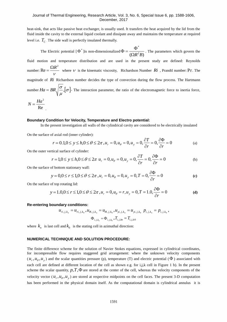
From this study one can conclude that the heat flow also maintains the axisymmetric behavior under the
chosen conditions. This axisymmetric behavior can also be observed from the isotherms plotted in r planes
or y=constant planes Figure 9.
a)
b)
c)
Figure 9. Contours of Isotherms in (r ) plane of cylindrical cavity at Re=1290, AR=1.5, Ri =0.05,
Pr=1.0 at different height (y-constant plane) (a) y = 0:1(b) y = 0:75, (c) y = 1:4.
To investigate the influence of Re and Ri on the overall heat transfer, the average Nusselt number has been
calculated for this annuals cylindrical cavity of Ar=1.5. The average Nusselt number Nu is shown as a function
of Re in Figure 10 and as a function of Ri in Figure 11. It can be observed that rate of change Ne with Re
decreases drastically as Ri is increased from 0.0 to 1.0. From this one can conclude that the overall heat transfer
by convection increases with increase in Re but decreases with increase in Ri.

Journal of Thermal Engineering, Research Article, Vol. 3, No. 6, Special Issue 6, pp. 1588-1606, December, 2017
1599
Figure 10. At AR =1.5, Pr= 1.0, for different Richardson number; variation of average Nussent number at
different Reynolds number.
Figure 11. At AR =1.5, Pr= 1.0, for different Reynolds number; variation of average Nussent number at
different Richardson number.
Journal of Thermal Engineering, Research Article, Vol. 3, No. 6, Special Issue 6, pp. 1588-1606, December, 2017
1600
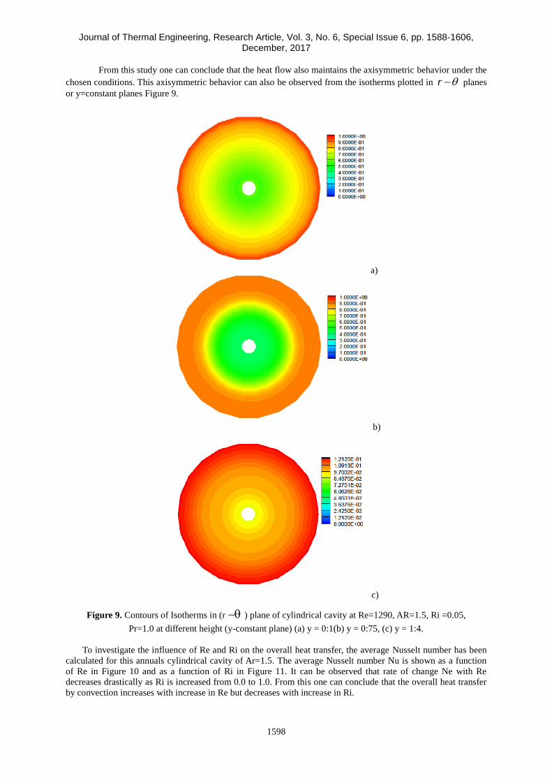
Figure 12. At AR =1.5, Pr= 1.0, for different Richardson number; variation of co-efficient of torque number at
different Reynolds number.
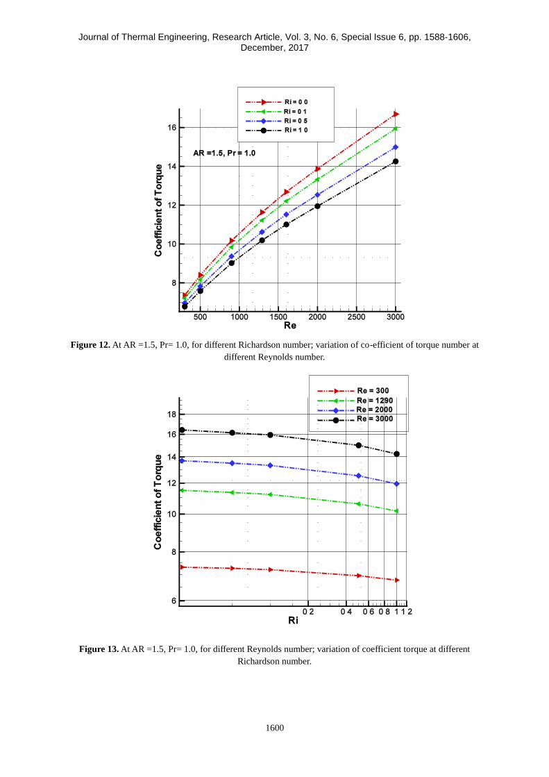
Figure 13. At AR =1.5, Pr= 1.0, for different Reynolds number; variation of coefficient torque at different
Richardson number.

Journal of Thermal Engineering, Research Article, Vol. 3, No. 6, Special Issue 6, pp. 1588-1606, December, 2017
1601
For engineering applications one may be interested to calculate torque coefficient CT
necessary to sustain the top disc rotation with uniform speed. Figure 12 shows that CT is an increasing
function of Re.
For a given Reynolds number the value of CT slightly decreases when Ri is increased over the
parameter range covered in the present study as can be seen in Figure 13. Hence, it may be possible to
control the magnitude of torque required by appropriately imposing a vertical thermal boundary condition on to
end walls of the cavity.
a) 2-D b) 80 c) 160 d) 240 e) 320
Figure 14. Steam contours in different (r-y) meridional plane of cylindrical cavity for Re =1290, AR =1.5, Ha
= 10.0.
a) b)
c)
Figure 15. Comparison of Radial profile of azimuthal velocity component of 2-D with 3-D for Re =1290, AR
=1.5, Ha = 10.0 at different axial height a) y =1.4, b) y=0.75, c)y =0.1.

Journal of Thermal Engineering, Research Article, Vol. 3, No. 6, Special Issue 6, pp. 1588-1606, December, 2017
1602
Case III (a): 3-D Lid driven swirling flow in a cylindrical annulus with axial magnetic field with
Ha=10.0.
Under influence of an axial magnetic field the 3-D swirling flow has been investigated for Re =1290,
AR =1.5, and Ha =10. In this case it is assumed that all surfaces of cylindrical annular cavity are electrically
insulated. Under these conditions the vortex breakdown completely vanishes as shown in stream contours in r-y
plane for both 2-d axisymmetric and 3-d flow situations Figure 14.
Furthermore, from Figure 14 it can be observed that, for the given conditions of the case, the 3-D flow
shows axisymmetric behavior under the influence of axial magnetic field. The same can also be observed from
the quantitative comparison of the azimuthal velocity in y=constant planes, Figure 15.
Figure 16. At AR =1.5, Pr=1.0, for different Ha number; variation of average Nusselt number at different
Richardson number.
Figure 17. At AR =1.5, Pr=1.0, Ri =0.05, for different Reynolds number number; variation of average Nusselt
number at different Ha number.

Journal of Thermal Engineering, Research Article, Vol. 3, No. 6, Special Issue 6, pp. 1588-1606, December, 2017
1603
To analyze the influence axial magnetic field on the heat transfer rate swirling flow in the annuals cavity
with both axial heat gradient and axial magnetic field has been studied. Figure 16 shows the variation of Nu
with Ri for Hartmann Number Ha ranging from 0 to 20 with fixed values of Pr=1.0 & Re=1290. A slight
decrease in the average Nusselt number with increasing value of Ha indicates that the heat transfer by convection
decreases with increase of strength of magnetic field. This indicates that the presence of magnetic field tends to
suppress the convective heat transfer and its effect increases with increase in Ri. Further, the variation of Nu with
Ha for fixed values of Ri=0.05 & Pr=1.0 with Re =900 to 3000 is shown in Figure 17. Form Figure 17 it can be
observed that rate of decrease of Nu with Ha reduces slightly with decreasing value of Re.
CONCLUSION
Various simulations of three dimensional lid driven swirling flows, in an annular cavity, with and without axial
magnetic field or the axial temperature gradient has also been carried out. It has been observed that within the
steady flow zones, with or without vortex breakdowns, the axisymmetric nature of the flow is maintained.
Moreover, the effects of governing parameters Re, Ri and Ha on the overall heat transfer has been discussed by
investigating the nature of variation of the average Nusselt number with these parameters.
Non-dimensional numbers
hy
hy
TNu
Local Nusselt number
1
0
2)(1
drrNuNu h
Average Nusselt number
drry
uC
hy
T
221
Co-efficient of torque
,BRHa Hartmann Number
Re
2HaN Interaction parameter
Re Reynolds number
2R
Ri Richardson Number 2
)(
R
TTg Ch
Pr Prandtl Number
Symbols
AR Aspect ratio = H/R
B Magnetic Field [kg/s3A]
rFl . Lorentz force in radial direction [N]
yFl
Lorentz force in axial direction [N]
Fl Lorentz force in azimuthal direction [N]
g- acceleration due to gravity [m/sec2]
H Height of cylinder [m]
R Radius of the cylinder[m]
r, h Non-dimensional radius and height of cylinder
p Non-dimensional pressure
r Non-dimensional radius of rotating lid,
cylindrical cavity and bottom stationary wall.
yr,
Non-dimensional meridional coordinate

Journal of Thermal Engineering, Research Article, Vol. 3, No. 6, Special Issue 6, pp. 1588-1606, December, 2017
1605
T Non-dimensionless Temperature
hT Non-dimensional temperature at top lid
CT Non-dimensional temperature at bottom wall
t Non-dimensional time .
yr uuu ,, Non-dimensional velocity components in the
radial azimuthally and axial directions respectively.
Greek Symbol
Kinematic viscosity [m2/sec]
Thermal diffusivity.[m2/s]
Thermal expansion coefficient of fluid.[1/K]
Fluid Electrical conductivity[s3A2/m3kg]
Dynamic viscosity [kg/m sec]
Constant angular speed of top rotating disc[rad /sec]
Non-dimensional stream function
t Discrete time interval
x length of each grid element
y height of each grid element
Angular width of each grid element (radian)
Subscripts: c Cold
h Hot
yr ,, Radial, Axial and Azimuthal directions, respectively
Electric potential
kji ,, Indices to identify a cell
REFERENCES
[1] Escudier, M. P. "Observations of the flow produced in a cylindrical container by a rotating endwall." Experiments in fluids
2, no. 4 (1984): 189-196.
[2] Hourigan, K., L. J. W. Graham, and M. C. Thompson. "Spiral streaklines in pre‐vortex breakdown regions of
axisymmetric swirling flows." Physics of Fluids (1994-present) 7, no. 12 (1995): 3126-3128.
[3] Stevens, José L., Z. Z. Celik, B. J. Cantwell, and J. M. Lopez. "Experimental study of vortex breakdown in a cylindrical,
swirling flow." (1996).
[4] Fujimura, Kazuyuki, Hide S. Koyama, and Jae Min Hyun. "Time-dependent vortex breakdown in a cylinder with a
rotating lid." Journal of fluids engineering 119, no. 2 (1997): 450-453.
[5] Spohn, A., M. Mory, and E. J. Hopfinger."Experiments on vortex breakdown in a confined flow generated by a rotating
disc." Journal of Fluid Mechanics370 (1998): 73-99.
[6] Blackburn, Hugh M., and J. M. Lopez. "Symmetry breaking of the flow in a cylinder driven by a rotating end wall."
Physics of Fluids 12, no. 11 (2000): 2698-2701.
[7] Sotiropoulos, Fotis, and Yiannis Ventikos. "The three-dimensional structure of confined swirling flows with vortex
breakdown." Journal of Fluid Mechanics 426 (2001): 155-175.
[8] Vogel, H. U. 1968: Experimentelle Ergebnisse t~ber die laminare Str6mung in einem zylindrischen Geh~iuse mit darin
rotierender Scheibe. MPI Bericht 6.
[9] Ronnenberg, B. 1977: Ein selbstjustierendes 3-Komponenten-Laserdoppleranemometer nach dem
Vergleichsstrahlverfahren,angewandt far Untersuchungen in einer station~ tren zylinder symmetrischen Drehstr6mung mit
einem Rt~ckstromgebiet. MPI Bericht 20.
[10] Escudier, M. P., and J. J. Keller. Vortex breakdown: a two-stage transition.BROWN BOVERI RESEARCH CENTER
BADEN (SWITZERLAND), 1983.
[11] Lopez, J. M. (1990). Axisymmetric vortex breakdown Part 1. Confined swirling flow. Journal of Fluid Mechanics, 221,
533-552.
[12] Lugt, H.J. and Abboud, M., 1987, “Axisymmetric vortex breakdown with and without temperature effects in a container
with a rotating lid,” Journal of Fluid Mechanics., 179, pp.179-200.
[13] Bessaïh R, Marty P, Kadja M. Numerical study of disk driven rotating MHD flowof a liquid metal in a cylindrical
enclosure. Acta Mech 1999; 135:153.

Journal of Thermal Engineering, Research Article, Vol. 3, No. 6, Special Issue 6, pp. 1588-1606, December, 2017
1606
[14] Bessaïh R, Kadja M, Eckert K, Marty P. Numerical and analytical study of rotating flow in an enclosed cylinder under
an axial magnetic field. Acta Mech2003; 164:175.
[15] Gelfgat YM, Gelfgat AY. Experimental and numerical study of rotating magnetic field driven flow in cylindrical
enclosures with different aspect ratios. Magnetohydrodynamics.2004; 40:147.
[16] Lee, C. H., & Hyun, J. M. (1999). Flow of a stratified fluid in a cylinder with a rotating lid. International journal of heat
and fluid flow, 20(1), 26-33.
[17] Kim, W. N., & Hyun, J. M. (1997). Convective heat transfer in a cylinder with a rotating lid under stable
stratification. International Journal of Heat and Fluid Flow, 18(4), 384-388.
[18] Iwatsu, R. (2004). Flow pattern and heat transfer of swirling flows in cylindrical container with rotating top and stable
temperature gradient. International journal of heat and mass transfer, 47(12), 2755-2767.
[19] Chen, S. (2011). Entropy generation inside disk driven rotating convectional flow. International Journal of Thermal
Sciences, 50(4), 626-638.
[20] Dash S., and Singh N., 2016, “Effects of Partial Heating of Top Rotating Lid With Axial Temperature Gradient On
Vortex Breakdown In Case Of Axisymmetric Stratified Lid Driven Swirling Flow,” Yildiz Technical University Press,
Istanbul, Turkey , J. Thermal Eng., 2(Sp. Issue 4), pp. 883-896.
[21] Gefagat A. Y. , Destabilization of free convection by weak rotation, 9th international conference heat transfer fluid
mechanics and thermodynamics,16-18 july 2012,Malta.
[22] Bessaïh R, Boukhari A, Marty P. Magnetohydrodynamics stability of a rotatingflow with heat transfer. Int Commun
Heat Mass 2009; 36:893.
[23] Mahfoud B, Bessaih R. Oscillatory swirling flows in a cylindrical enclosure with co-/counter-rotating end disks
submitted to a vertical temperature gradient. Fluid Dynamics & Materials Processing. 2012; 8:1.
[24] Verzicco, R., and P. Orlandi. "A finitedifference scheme for three-dimensional incompressible flows in cylindrical
coordinates." Journal of Computational Physics 123, no. 2 (1996): 402-414.
[25] Barbosa, Emerson, and Olivier Daube. "A finite difference method for 3D incompressible flows in cylindrical
coordinates." Computers & fluids 34, no. 8 (2005): 950-971.
[26] Fukagata, Koji, and Nobuhide Kasagi. "Highly energy-conservative finite difference method for the cylindrical
coordinate system." Journal of Computational Physics 181, no. 2 (2002): 478-498.
[27] Chorin, A. J., A Numerical method for solving incompressible viscous flow problems, Journal of Comput. Phys., Vol 2,
pp 12-26, 1967.
[28] Peyret, R.&Taylor, D.(1983). Computational methods for fluid flow;SprigerVerlag.