study of curved, descending, decelerating,
TRANSCRIPT

NASA TECHNICAL NOTE ci' NASA T N ?D- 8190
z E
A SIMULATION STUDY OF CURVED, DESCENDING, DECELERATING,
Luugley Reseurch Center Hdmpton, 'vu. 23665
- , , . '
' i . . . . 1 .
. I c I : ,
N A T I O N A L AERONAUTICS A N D SPACE A D M I N I S T R A T I O N W A S H I N G T O N , D. C. A P R I L 1976 I e is
...
9. Performing Organization Name and Address
TECH LIBRARY KAFB, NM
513-52-01-18
.
1. Report No. 1 2. Goveinment Accession No.
I NASA TN D-8190 4. Title and Subtitle
A SIMULATION STUDY O F CURVED, DESCENDING, DECELERATING, LANDING APPROACHES FOR TRANSPORT AIRCRAFT
J a m e s E. Dieudonne, Randall D. Grove, 7. Author@)
I llllll I lllll I I lHll1llll Ill1 Ill1 0333759
5. Report Date
6. Performing Organization Code
April 1976
L- 10584 8. Performing Organization Report No.
5. Supplementary Notes
- 6 Abstract
During recent yea r s the problems of congestion, noise pollution, and safety in the vicinity of a i rports have indicated that changes must be made in the operational aspects of a i rcraf t land- ing approaches. Suggested changes include curved approaches, s teep approaches, decelerating approaches, and combinations of these. This paper descr ibes a system which is capable of con- trolling an aircraft automatically along a curved, descending, decelerating approach. A simu- lation study was conducted to determine the necessary modifications to the basic flight-proven control system. This basic system is presently being used to accomplish straight-in automatic landing approaches on a short-haul transport a i rcraf t (B-737 terminal configured vehicle). This study shows that both 3' (normal) and 5' (steep) approaches could be accomplished with only minor modifications to the basic control system.
- 7. Keywords (Suggested by Authoris) )
Automatic landing Curved approach Decelerating approach
. .~
18. Distribution Statement
Unclassified - Unlimited
Subject Category 08 9. Security Classif. (of this report] 20. Security Classif. (of this page) 1 21. ;;. of Pages
Unclassified Unclassified $3.75 -
For sale by the National Technical Information Service, Springfield, Virginia 221 61
L

A SIMULATION STUDY OF CURVED, DESCENDING, DECELERATING,
LANDING APPROACHES FOR TRANSPORT AIRCRAFT
James E . Dieudonne, Randall D. Grove, and George G. Steinmetz Langley Research Center
SUMMARY
During recent years the problems of congestion, noise pollution, and safety in the vicinity of a i rports have indicated that changes must be made in the operational aspects of a i rcraf t landing approaches. Suggested changes include curved approaches, steep approaches, decelerating approaches, and combinations of these. This paper describes a system which is capable of controlling an aircraf t automatically along a curved, descend- ing, decelerating approach. A simulation study w a s conducted to determine the necessary modifications to the basic flight-proven control system. being used to accomplish straight-in automatic landing approaches on a short-haul t rans- port a i rcraf t (B-737 terminal configured vehicle). This study shows that both 3' (normal) and 5' (steep) approaches could be accomplished with only minor modifications to the basic control system.
This basic system is presently
INTRODUCTION
Aircraft operations in the terminal a r e a have been the topic of many studies in recent years. the future require that changes in terminal area operations be made. At present, a i rcraf t are usually vectored along straight-line paths to a common point; the ai rcraf t are then sequenced to follow each other down a shallow flight path for a straight-in approach to the runway. Present procedures a lso dictate that the entire final approach be flown a t the desired landing speed and in a landing configuration.
The increased traffic in the terminal a r e a and the projected further increase in
As pointed out in reference 1, these paths often result in low-altitude flying over densely populated a r e a s a t relatively high power settings. The additional noise pollution and the safety hazards of flying a t low altitudes make the procedure objectionable. flight paths and two-segment final approaches (ref. 1) have been proposed as solutions to these problems. Curved approaches (refs. 2 , 3 , and 4) have also been proposed as an alternative to these procedures. The steep curved approach has certain advantages: it keeps the aircraf t a t relatively high altitude, except in the immediate a r e a of the airport ,
Steeper

and it routes traffic away from densely populated a reas . A deceleration to landing speed during the final approach has also been recommended (ref. 5) as an aid in the reduction of noise pollution. This paper proposes a steep-curve, decelerating final approach which combines all the advantages of the flight paths recommended earlier.
The paper describes the design of a system to control an aircraft along this approach. This design is a modification of a flight-proved inertially augmented automatic landing sys- tem designed to accomplish a straight-in approach using the standard instrument landing system (ILS). presently being flown on the B-737 aircraft as part of the terminal configured vehicle (TCV) program.
The unmodified or basic system is documented in references 6 and 7 and is
The paper describes a simulation study which investigated the design of a system capable of controlling an aircraft along a curved, descending, decelerating path. ulation of the B-737 is very complete in that it contains a nonlinear aerodynamics package together with realistic representations of onboard avionics, guidance and control systems, and actuators; such realism enhances confidence in the results obtained. Results a r e pre- sented for the curved decelerating approaches along both 3' and 5' glide paths. The tes ts included the simulation of turbulence, winds, and noise representing very high frequency omnirange and microwave landing system er rors .
The sim-
AC
Cknob
Dtg
GSA
GSE
g
h
Kd
Kt
Q@
2
SYMBOLS
acceleration e r r o r signal, m/sec2
knob input for Vc, knots
path distance to threshold, m
glide-slope angle, deg
glide-slope e r r o r , deg
gravity, m/sec2
radio altitude, m
1/100 of desired glide-slope angle (0.03 and 0.05)
tangent of glide-slope angle to be flown (0.0524 and 0.0875)
distance of glide-slope location from runway threshold, m

Qr
Qt3
(2
R
sP
S
t
V’
VC
vcd
vg
V i
Vt
VY
length of runway, m
distance between runway threshold and point 3, m
body pitch rate , deg/sec
radius of turn, m
flight spoiler position, deg
Laplace operator
time, sec
autothrottle wind shear compensation command, m/sec2
calibrated airspeed, knots
desired calibrated airspeed, knots
groundspeed, m/sec
indicated airspeed, knots
t rue airspeed, m/sec
crosstrack velocity, m/sec
XR,YR,ZR local coordinate system
XT ,YT ,ZT
X,Y ,Z
XAT,YAT ,ZAT
a!
P
turn center coordinate system
aircraf t position relative to local coordinate system
aircraft position relative to turn center coordinate system
aircraft angle of attack, deg
angle for determining flight-path segment, deg
3
I

Y flight-path angle, deg
Ah,AY
Ahnor ,Aynor
vertical and lateral e r r o r s from path, m
normalization variables for glide-slope and localizer e r r o r signals, m
decrab command to aileron, deg
track-angle e r r o r between aircraf t and path, deg
aileron command, deg
elevator command, deg
glide-slope e r r o r command, deg
flap position, deg
rudder command, deg
commanded change in throttle position, deg
localizer e r r o r signal, deg
variable limit on localizer e r r o r signal
pitch attitude, deg
roll angle, deg
roll-angle command, deg
roll-angle e r r o r , deg
lateral e r r o r signal, deg
nominal bank angle (curved path), deg
roll rate limit, deg/sec

Q aircraft heading, deg
Qr path heading, deg
aircraft t rack angle, deg Qt
Abbreviations :
AGCS
DME
HDG
HPC
ILS
INS
MLS
ONCOR
RSFS
TCV
VOR
VPC
automatic guidance and control system
distance measuring equipment
runway heading
horizontal path command
instrument landing system
inertial navigation system
microwave landing system
on-course logic
research support flight system
terminal configured vehicle
very high frequency omnirange
vertical path command
A dot over a symbol denotes a time derivative; the symbol I I denotes an absolute value.
DESCRIPTION OF SIMULATION
This study was conducted by use of a simulation of the research support flight sys- tem (RSFS) described in reference 8. The simulation w a s conducted on the real-t ime
5
I

simulation subsystem (ref. 9) at the Langley Research Center; the simulation included a representation of the major components shown in figure 1.
The aircraft mathematical model was a representation of a B-737 aircraft. The model included a nonlinear data package fo r all flight regions, a nonlinear engine model, and nonlinear models of servos, actuators, spoiler mixers , and other associated flight hardware. The simulation of the basic a i r f rame was verified as realistic by comparing simulation data with actual aircraft response data and by pilot evaluation. Approxima- tions of VOR, DME, and MLS models were used.
The functions of the navigation-guidance and flight control computers are shown in more detail in figure 2 and are described in references 6 and 7. A complete represen- tation of all the flight control systems (control wheel steering, navigation, autoland) and associated logic is in the simulation. The mode of the simulation is controlled by the AGCS mode select panel. Inputs to the navigation computer are made by the navigation control and display unit (NCDU) f rom which the flight plan can be initiated or altered. (The NCDU was not used in this study.)
The pr imary displays include an electronic attitude direction indicator (EADI) and a n electronic horizontal situation indicator (EHSI). These displays are generated by an Adage graphic system and a r e sent by closed circuit television to the cockpit to be dis- played on cathode r ay tubes. These displays were not necessary for this particular study. The displays were used as monitoring devices and were included to show the totality of the Simulation.
FLIGHT-PATH DESCRIPTION
The approach path is shown in figure 3 and can be defined by the navigation-guidance equations in reference 6. These navigation equations were modified to meet the require- ments of the autoland control system fo r this flight path. The functional aspects of the path are: (1) a deceleration from 200 knots to an approach speed of 120 knots requiring automatic deployment of flaps, flight spoilers, and actuation of the throttles; (2) a constant radius turn with a heading change of 180°; (3) a short (1524 m) final leg to threshold; and (4) a steep, constant descent during the entire approach.
The flight path was divided into segments, and logic was developed to determine the particular segment as a function of the current a i rcraf t position. The required a i rc raf t position (x,y,z) was determined relative to a local coordinate system. The local coordi- nate system (XR,YR,ZR) chosen for this study was located at the threshold of the runway and was oriented as shown in figure 3. During the study, it was assumed that the aircraf t position (x,y,z) was obtained by regular radio navigation means from point 0 to point 1
6
I I I 1111 I I I 1 1 1 . 1 1 1 1 1 1 1 . 1 1 1 1 1 1 1 . I I I 1 I1 111 111.11 .I I. 1.111.1. ,111 1 1 1 I, ,I I

and by MLS f rom point 1 to touchdown. point 0 represent errors in reaching the flight path by other means.
Initial offsets of the aircraft from the path at
The origin of the turn center coordinate system (XT,YT,ZT) was located at the cen- ter of the turn and was oriented as shown in figure 3. The a i rc raf t position relative to this coordinate system is calculated as
The particular segment of the flight path is determined from the angle p where
1 'AT 180 p = tan- - - Z~~ 7T
(-360' < p 5 0')
The lateral e r r o r between the a i rc raf t and the path is defined as that distance along
(See fig. 3.) With this position known, the path heading and The vertical e r r o r is calculated from a i rc raf t altitude
Hence, given the a i rc raf t posi-
a groundpath projection vector where the vector is perpendicular to the path and passing through the a i rc raf t position. the distance to go a r e determined. compared with path height as a function of distance to go. tion and a prior defined path, the lateral e r r o r Ay, vertical e r r o r Ah, distance to go Dtg, and desired heading Gr can be determined.
however, for the autoland system the deviations have to be normalized o r scaled in t e r m s of glide-slope and localizer e r r o r s . The simulated ILS beam shapes a r e shown in fig- u re 4. The effective beam shapes a r e cylindrical f rom point 0 to point 2, where the 64-m glide-slope e r r o r is 0.7O and the 351-m localizer e r r o r is 2.5O for full-scale deflections. F rom point 2 until touchdown the beam narrows as a function of distance to go. The nor- malization variables for the glide slope and localizer are constant between point 0 and point 2 where Ahnor = 64 m and AYnor = 351 m , respectively. These variables decrease in value f rom point 2 until touchdown as a function of distance to go.
The la teral and vertical deviations a r e suitable for a navigation-guidance system;
The equations used for each segment of the flight path follow.
Point 0 to point 1:
00 2 p > -900
7

Dtg = Qt3 + BR + XAT
+, = 270'
Ay = -y - 2R
Ah = h - (Dtg + Qgt) tan (GSA)
Aynor = 351
Ah,,, = 64
Point 1 to point 2:
-90' 1 p > -180'
+, = 360' + p
Ah = h - (Dtg + Qgt) tan (GSA)
Aynor = 351
Ah,,, = 64
Point 2 to point 3:
-180' 2 p > -270'
8
I

Ah = h - (Dtg + Qgt) tan (GSA)
Ahnor = tan (0.70)(Dtg + Po)
Point 3 to threshold:
-270' 2 p > -360'
uJr = 900
AY = Y
Ah = h - (Dt, + Pgt) tan (GSA)
AYnor = tan (2.5')(Dtg + E r )
The glide-slope and local izer-error equations are
Ah Ahnor
GSE = 0.7 ~
and
AY 7 = 2.5 - AYnor
9

RESULTS AND DISCUSSION
The f i r s t attempt to fly the simulated curved approach used the basic autoland con- t ro l algorithms with continuous desired t rack angle replacing runway heading and with the simulated glide-slope and localizer-error signals. (See figs. 5 to 8.) The simulation was flown with no regard for the deceleration requirement, and the resul ts exhibited the problem of a path standoff e r r o r during the curved portion of the task. The problem occurred because the existing autoland system was designed for a straight-in approach and the bank angle $ necessary for the turn could only be generated by a nonzero local- i ze r e r r o r . The nonzero localizer e r r o r keeps the track-angle e r r o r nulled whereas the reverse is not true. A solution was to provide the control system with the nominal bank angle required to fly the turn of radius R a t the current ground speed The equa- tion used fo r the calculation of the nominal bank angle was (ref. 6)
Vg.
A s shown in figure 5, is summed with t rack angle and localizer e r r o r s to form a commanded bank angle This signal is then combined with the actual roll attitude of the aircraf t to form an e r r o r signal @er commands a change in aileron posi- tion to roll the ai rcraf t to the correct attitude. With the addition of the the simulation was run for a 120-knot, full-flap, 3' curved approach, and the resu l t s are shown in figure 9. I t should be noted that the on-course logic (ONCOR) shown in figure 5 was not allowed to be se t f f t rue7T until the short final leg. This modification prevented the switching to the long-time constant in the localizer e r r o r circuit and to the lower bank- angle limit. A s shown in the figure, the ai rcraf t followed the desired groundpath very closely. The only noticeable e r r o r occurred a t the initiation of the turn.
@c. $er; the
$nom signal,
This transient e r r o r is more pronounced in a 200-knot, zero-flap, 3' curved approach. (See fig. 10.) This e r r o r occurred because a s tep input w a s placed into the
signal at the turn initiation. The aircraf t could not follow the step; therefore, the overshoot shown in the figure occurred. To reduce this overshoot in the early stages of transition from the straight segment to the curved portion of the path, the s tep of @nom was introduced before the aircraf t reached the actual point of turn initiation. of time necessary to roll to the desired q5nom is approximately equal to the nominal bank angle divided by the roll ra te limit of the control system (ref. 6)
The amount
h o m
@limit At = 7
10

I
The roll command is then initiated when the distance to go is equal to the distance to go at point 1 (Dtg 1) added to A t multiplied by the groundspeed
Dtg = Dtg,l + (VgAt)
The same approach could be used for the initiation of the roll-out maneuver; however, this computation w a s not included since, at this point along the path for a decelerating approach, Gnom would be smaller .
during the final turn. As can be seen in the figure, the control system required almost the complete turn to null the initial overshoot e r r o r . bank command limit of the control system is *30° whereas the nominal bank angle for this 200-knot approach was -26'; thus, only 4O of bank command w a s left to nulf the ini- tial e r r o r . If deceleration had occurred prior to the turn, Gnom would have only been -12' and 1 8 O of bank command would have been left to null the overshoot.
Figure 10 also shows the importance of decelerating to approach speed prior to o r
This condition occurred because
The deceleration of the aircraf t from 200 knots to the desired landing speed of 120 knots was to be accomplished during the flight path. ation was to begin was chosen a t a specified path distance from the runway threshold. This distance was determined by minimizing flight time in the path while st i l l allowing the performance of a satisfactory automatic landing approach. The specified distances used were 6858 m for the 3' path and 13 904 m for the 5' path. deceleration task required the automatic deployment of the flaps and flight spoilers and the actuation of the throttles.
The point at which the deceler-
Performance of the
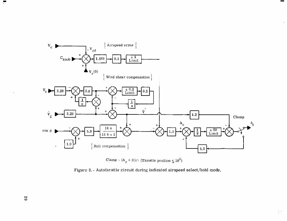
The throttles were controlled by using the "Indicated Airspeed Select/Hold" cir - cuit shown as part of figure 8. 0.61 m/sec2 to 1.22 m/sec2 in order to increase the deceleration capabilities for this study. (Dtg = Specified value), the desired airspeed vcd was set to the desired landing speed. (This signal generated a deceleration command A, which caused the throttles to re ta rd continuously until a prescribed lower limit was reached. The thrott les remained in the position until Ac craft a t the desired landing speed.
The acceleration command limit was changed from
Once the aircraf t reached the point on the path where deceleration was to begin
changed sign, and then the throttles moved forward, tr imming the air-
The deceleration command A, w a s a lso used to deploy the flight spoilers as speed brakes and to increase the deceleration capabilities of the aircraf t . As shown in figure 11, the flight spoilers were deployed and retracted at a predetermined rate (6O per sec) as a function of A,. It should also be noted that for safety reasons the flight spoi lers are not deployed below some minimum altitude. This limit prevents a possible hardover situation
11

caused by a spoiler failure at a lower altitude where recovery is questionable; the limit also allows the aircraf t to t r im prior to the initiation of the flare maneuver.
Although the throttles and flight spoilers are being driven, the flaps a r e also being deployed automatically as a function of indicated airspeed. be consistent with recommended flap placards.
This function was designed to (See fig. 12.)
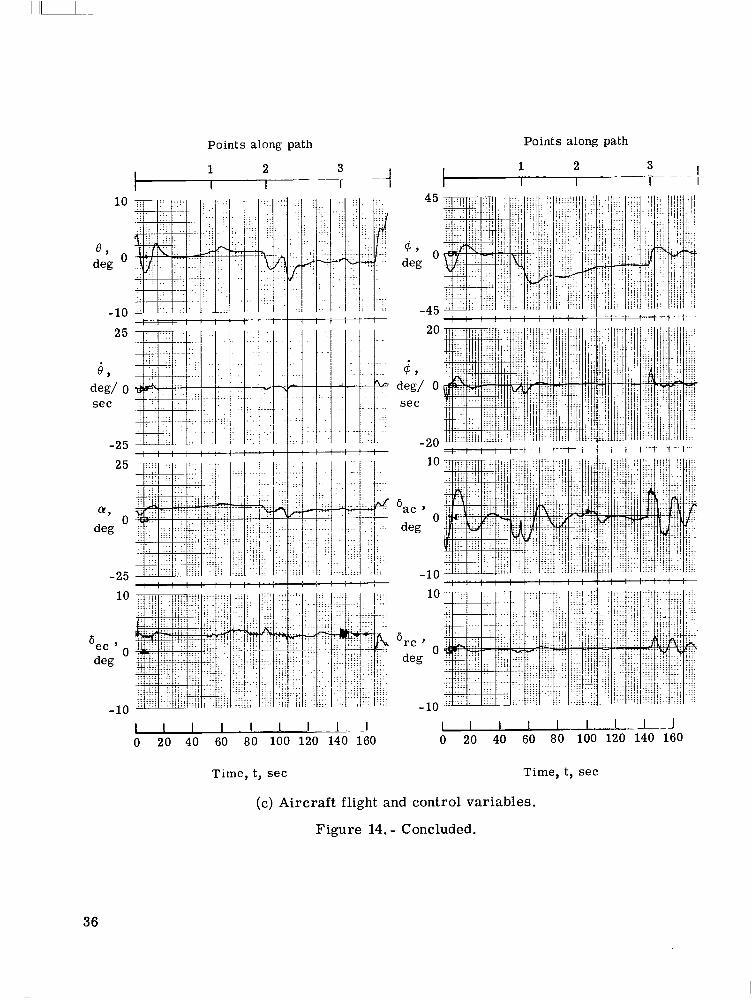
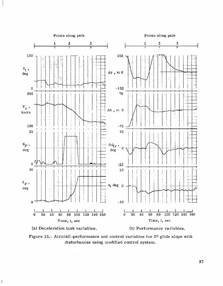
When turn anticipation was added and a deceleration from 200 knots to 120 knots carried out, the performance in flying the prescribed flight path was improved. histories of figure 13 and the tabulated resul ts in table I show that a very satisfactory curved, decelerating 3' approach can be accomplished with minor modifications to the basic automatic control systems in the perfect environment. The same is true for a 5' approach (fig. 14 and table 11) under the same conditions. The modified system was then tested in the presence of moderate turbulence and wind, beam discontinuities when switching from VOR and DME to MLS guidance information, and sensor noise. Several simulation runs were made with crude approximations to these e r r o r s added into the simulation. Figures 15 and 16 and tables I11 and IV depict candidate 3 O and 5O runs, respectively, and show that the modified system performed satisfactorily even in the presence of the disturbances listed in table V. in figure 15 and table IV was caused by the high ground speed of the aircraft. conditions, performing the deceleration sooner would probably be advisable.
The time
The relatively large lateral e r ror Ay For these
A possible autoland configuration for curved, descending, deceleration approaches, shown in major block form in figure 17, includes the proposed modifications to the pres- ent system. These relatively minor modifications are:
(1) Coupling of the navigation-guidance computer to the flight control computers during the autoland
(2) Addition of an algorithm to the navigation-guidance package; such an addition would convert microwave landing system position information into usable glide-slope and localizer e r r o r s
(3) Replacement of the static runway heading signal with a continuous desired track signal
(4) Addition of a nominal bank-angle signal to the lateral autoland control system
(5) Addition of "turn anticipation" to path definition
(6) Addition of an automatic flight spoiler control system
(7) Addition of an automatic flap control system.
12

CONCLUDING REMARKS
This study was made to determine a candidate guidance-autoland control system which would functionally meet the requirement of performing a fully automatic landing approach along a curved, descending, decelerating path. Such a system was obtained by modifying the basic control laws and could be implemented, hardware interface permit- ting, on the research support flight system with the present onboard computers. A pos- sible autoland configuration for curved, descending, deceleration approaches includes the proposed modifications to the present system. These relatively minor modifications are:
(1) Coupling of the navigation-guidance computer t o the flight control computers during the autoland
(2) Addition of an algorithm to the navigation-guidance package; such an addition would convert microwave landing system position information into usable glide-slope and localizer e r r o r s
(3) Replacement of the static runway heading signal with a continuous desired track signal
(4) Addition of a nominal bank-angle signal to the lateral autoland control system
(5) Addition of "turn anticipation" to path definition
(6) Addition of an automatic flight spoiler control system
(7) Addition of an automatic flap control system.
Langley Research Center National Aeronautics and Space Administration Hampton, Va. 23665 March 4, 1976
13

REFERENCES
1. &eder, John P.; Taylor, Robert T.; and Walsh, Thomas M.: New Design and Operating Techniques fo r Improved Terminal Area Compatibility. Automot. Eng., Apr. -May 1974.
[Preprint] 740454, SOC.
2. Hoffman, William C.; Zvara, John; and Bryson, Arthur E., Jr.: A Landing Approach AIAA Pape r No. 69-865, Aug. Guidance Scheme for Unpowered Lifting Vehicles.
1969.
3. Burrows, J a m e s W.; and Tobie, H. N.: Linear Energy Management During Unpowered Landing Approach. Doc. No. D6-24909TN, Boeing Co., [1971].
4. Crawford, Daniel J.; and Bowles, Roland L.: Automatic Guidance and Control of a Transport Aircraft During a Helical Landing Approach. NASA TN D-7980, 1975.
5. Reeder, John P.: Future Airborne Systems for Terminal Area Operations. Paper Pre- sented at the 18th Symposium of the Society of Ekperimental Tes t Pilots, Sept. 1974.
6. McKinstry, R. Gill: Guidance Algorithms and Non-Critical Control Laws for ADEDS and the AGCS. Model NASA 515. Doc. D6-41565, Boeing Co., 1974.
7. Bjurman, B. E.; Jones, D. L.; McKinstry, R. G.; and O'Toole, P. L.: Supplemental Flight Test Report. Doc. D6-41593, Boeing Co., 1974.
8. Salmirs, Seymour; and Tobie, Harold N.: Electronic Displays and Digital Automatic Control in Advanced Terminal Area Operations. 1974.
AIAA Paper No. 74-27, Jan.-Feb.
9. Grove, Randall D.; and Mayhew, Stanley C.: A Real-Time Digital Program for Estimat- ing Aircraft Stability and Control Pa rame te r s F rom Flight Tes t Data by Using the Maximum Likelihood Method. NASA TM X-2788, 1973.
14

TABLE 1.- CURVED PATH RESULTS FOR 30 GLIDE SLOPE
Path distance Lateral Vertical Calibrated Pitch Flap Roll Ve rt ic a1 Track to threshold, e r ror , e r ror , airspeed, attitude, position, attitude, speed, e r ror ,
Dtg, m AY, m Ah, m vc, knots 0, deg 6 ~ , deg @, deg h, m/sec A++.., deg
13 904
8 418
4 971
1 524
219 ~
152.40 -134.11
-5.79 .85
16.06
1.37
-11.12
-12.92
-5.97
-5.12
-4.21
.49
-5.43
-4.32
-2.66
-2.57
-2.47
-2.72
205.8
205.0
187.2
127.1
123.9
122.8
122.1
121.6
121.2
3.8
1.1
2.9
-0.0
1.1
.4
.6
.5
.9
2.5
2.3
7.6
40.0
40.0
40.0
40.0
40.0
40.0
0.0
-10.9
-22.5
-11.3
6.7
1.7
-2.2
0.0
1.4
0.00
-5.50
-5.18
-3.23
-2.86
-3.25
-3.20
-3.29
-3.32
0.0
-2.4
-.3 I
-. 1
-.4

Path distance t o threshold,
Dtg,
13 904
8 418
4 971
1 524
1 2 1 9
9 14
6 10
305
0
TABLE 11. - CURVED PATH RESULTS FOR 50 GLIDE SLOPE
Lateral e r ror , AY, m
152.40
-46.02
4.27
3.35
-8.53
-13.41
-5.18
.30
-3.05
Vertical e r ro r , Ah, m
-23.77
-8.23
-4.27
-.61
-.61
-.61
-.61
-.61
-.61
Calibrated airspeed, Vc, knots
212.1
189.1
162.0
122.1
121.6
121.8
121.7
12 1.4
121.1
Pitch attitude,
0 , deg
3.5
.9
-.6
-1.0
-.7
-1.5
-1.2
-1.3
-1.3
Flap position, 6F, deg
2.5
8.8
29.2
40.0
40.0
40.0
40.0
40.0
40.0
Roll attitude,
$ 9 deg
0.0
-11.3
-18.2
-10.8
4.5
3.8
-. 5
-2.5
1.7
Vertical . Speed, h, m/sec
-0.04
-8.69
-6.61
-5.39
-5.21
-5.61
- 5.43
- 5.46
-5.43
0.0
-3.3
-. 5
-. 1
-2.4
.6
1.9
-. 2
-.4

TABLE III. - CURVED PATH RESULTS FOR 3O GLIDE SLOPE WITH DISTURBANCES
Path distance Lateral Vertical Calibrated Pitch Flap Roll Ve rt i c a1 Track airspeed, attitude, position, attitude, speed, e r ror , to threshold, e r ror , e r ro r ,
Dtg, m AY, m Ah, m Vc, knots 0, deg 6 ~ , deg @, deg h, m/sec A$C/tr, deg
13 904
8 418
4 971
1 524
1 2 1 9
9 14
6 10
305
0
152.40
-74.98
272.19
10.67
-.91
-1.52
-.46
-2.13
-.65
-134.11
18.29
-9.14
-1.22
.30
.91
-.30
.30
.30
205.7
202.0
186.2
120.5
121.4
121.4
118.7
119.0
119.0
3.8
.2
3.2
2.3
1.1
.4
1.7
1.3
1.4
2.5
3.0
5.2
40.0
40.0
40.0
40.0
40.0
40.0
0.0
-9.5
-29.4
-7.6
4.2
-1.0
-. 1
-.8
. 3
0.00
-5.79
-4.18
-2.26
-2.77
-2.90
-2.77
-2.68
-2.71
0.0
-1.8
-.6
-.6
-1.7
.7
-.4
-.3
. 3

TABLE 1V.- CURVED PATH RESULTS FOR 5 O GLIDE SLOPE WITH DISTURBANCES
Vertical speed,
6, m/sec
0.00
-10.00
-7.47
Path distance Lateral t o threshold, e r ror ,
13 904 152.40
8 418 -12.80
4 971 11.28
1 524 2.13
1 2 1 9 -6.71
Track er ror ,
AQtr, deg
0.0
-1.9'
-1.1
er ror , airspeed, Vc, knots
I
-23.77 1 211.9
-17.07 198.0
-6.10 ' 168.9
-1.52 121.4
-1.22 122.0
9 14 -4.27 -.91 122.3
6 10 2.44 -.91 119.8
305 -.91 -1.22 119.5
2.5
.3 4.6
1.4 20.5
-.6 40.0
-.9 40.0
-.8 40.0
-.l 40.0
-.l 40.0
0 -.91 -.61 i 120.3 -.2 ' 40.0
Roll attitude,
$ 7 deg
0.0
-10.6
-17.4
-8.9
4.8
-1.4
-1.4
.8
0.0
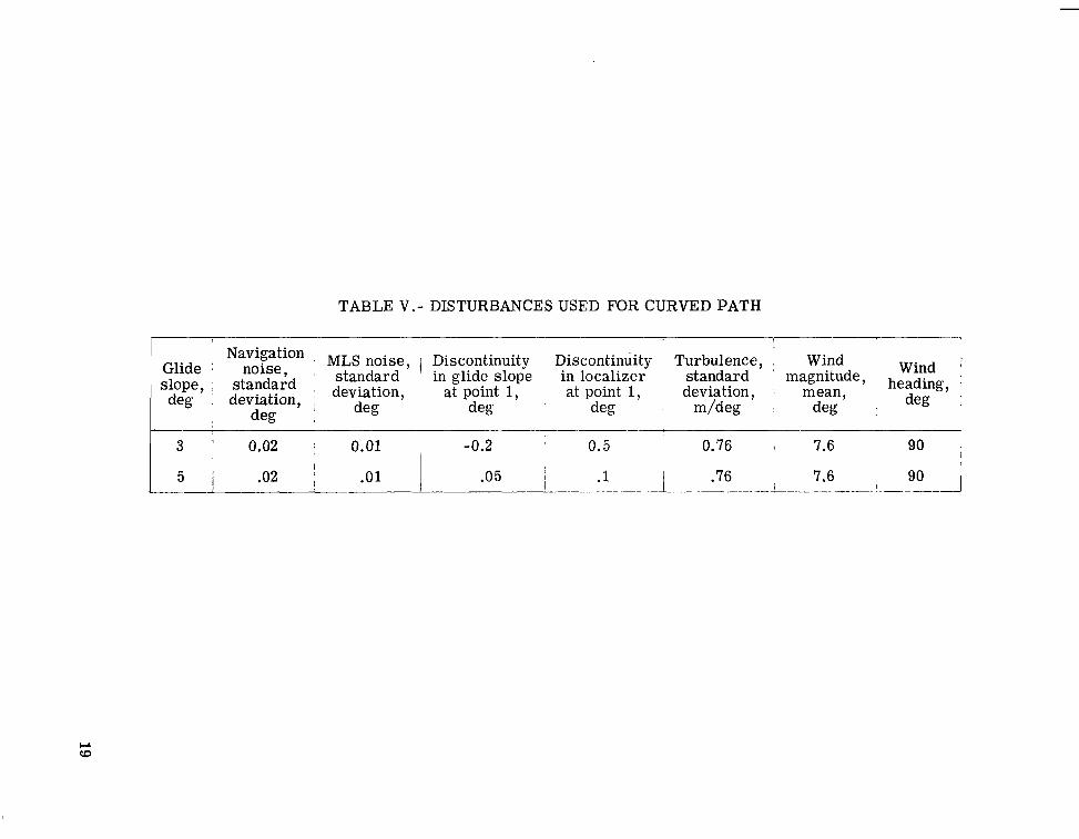
TABLE V.- DISTURBANCES USED FOR CURVED PATH
Wind Navigation MLS noise , 1 Discontinuity Discontinuity Turbulence, Wind Glide noise, 'lope, standard deviation, at point 1, at point 1, deviation, mean, deg deviation, ,
standard in glide slope in localizer standard magnitude , heading, deg deg deg m/deg deg I deg deg 8

-f
Navigation- guidance control and display unit
MLS
AGCS mode and parameter
se 1 e c t panel
Autothrottle servo
A A
t
- Primary displays
annunc iat o r s
Navigation-guidance Flight control 4 - computer computer * Servos
I
.i
Sensors: ra te gyros, INS, ILS, air data, radio altimeter
7- 1 mathematical
model
Figure 1. - Major components of research support flight system simulation.

~ . . .. , ,
Outer loop controls
--- - - - - - -- Navigation-guidance
algori thms
--------- Autothrottle controls
Glide-slope engage and
I cap tu re -_ - - - - - - - \c, HDG
Localize r engage and
cap tu re
De c rab
I
- - - - - - - - - -
\
Navigation -guidance c o mpn t er
ILS local izer e r r o r
Flight control computer
F igu re 2. - Basic autoland configuration.
21

[ ZR down]
1-3048 m I
Aircraft position 1 an0
I I\ 'C I U U
Runway threshold -I
t --t-2700
/ ( V c = 200 knots
= 3 O , 5 O
Figure 3. - Curved, descending, decelerating flight path.

o r '
Point 0:
D = 4971 m
0.7' of GSE = 64 m tg
Point 1:
0.7' of GSE = 64 m 2.5' of 17 = 351 m
Figure 4. - Equivalent instrument landing system beam shapes.

. r l ) .
1 {Beam gain programer
f77Q Limit
I
h 457
h I
{Beam limit programer 1
h 4 f 2 ( h ) : : [ / ~ ~ c o R 7 , o.5
152 305 h 2.0
S + 0.5 - %-
%om
0.6870
ONCOR s + 0.05
(a) Lateral e r ro r signal.
Figure 5. - Lateral autoland circuit.

+E-I-1 Limit ONCOR
f loo Limit
b 1.2 .
I f 10" Limit
Limit
b %C
$ +
1.22
{Variable gain}
20
s + 20
(b) Aileron command signal.
Figure 5. - Concluded.

N Q,
.. h
32.8 s + 1 0 -
I I - f 0.2 Limit GSE
+ 3.28 Kt Kd -
+ il
3.28 - h S + 0.0625
(a) Longitudinal e r r o r signal.
Figure 6.- Longitudinal autoland circuit; CAPT10 = 10 sec after (IGSEI 5 0.108).

' + \
1.34
(b) Elevator command signal.
Figure 6. - Concluded.

Decrab { Easy-on } * -
0 to 1 S Limit
+
+ S
Pilot rudder input Decrab
0 Deadband
Decrab = (h 246 m)
Figure 7. - Decrab circuit. Circuit including K,/s represents a track-hold function.
Airspeed e r ror I
+ 'knob 1.689
1 Wind s h e a r compensation
A & & -
1 ' + @ - ir f -1 Clamp
Clamp = (Ac < 0 )n (Throttle position 5 100)
Figure 8. - Autothrottle circuit during indicated airspeed select/hold mode.

----- Desired path Actual aircraft path
0
Figure 9.- Ground track for 3 O glidepath at 120 knots using control system without "turn anticipation."
30

- - - - Desired path - Actual a i rc raf t path
0
Figure 10.- Ground t rack for 3 O glidepath at 200 knots using control system without "turn anticipation."
31

Hysteresis
Autothrottle dzl ~
acceleration command w - - ---
Rate 0 limit
Integration Flight spoiler
u u w position command
* 1 - - S
+ 6'
1 /sec
Po sit ion limit
Figure 11. - Automatic flight spoiler circuit.
Vi, knots
Figure 12. - Open loop automatic flap circuit.

Points along path Points along path
I I I
2 50
Vc , knots
100
25
0
50 t L L
I I I I I I I I I I I I I I I I I I 0 20 40 60 80 100 I 2 0 140 160 0 20 40 60 80, 100 120 140 160
Time, t, s e c Time, t, s e c
(a) Deceleration task variables. (b) Performance variables.
Figure 13 . - Aircraft-performance and control variables for 3 O glide slope using modified control system.
33

Points along path Points along path
I ~ -~
10
0
, l o
-I, \
t i l I I I t 'III. 1 . i i I
I I I I I 1 I L -J 0 20 40 60 80 100 120 140 160
20 t t f - 1 i i i i i i . i i i
-- + + t I i i V i i i i i i i V i I i
10
- 10 10
-10
I I 1 1 1 1 1 I .J 0 20 40 60 80 100 120 140 160
Time, t, sec Time, t, sec
(c) Aircraft flight and control variables.
Figure 13. - Concluded.
34

I I I I
250
v c , knots
100
I r
I
1 I t
1.. ... .,. 152 -
AYY 0 m
-152
i
I !
ti'
Points along path 1 2 3 I I I -I
I : I I I + I : : I - ! I I I I I I r,fi
I : I I I + I : : I - ! I I I I I I
-2.5
Q
10
', degO
- 10 L 1 - L I I 1 I I I 1 1 1 1 . 1 I I I 0 20 40 60 80 100 120 140 lA0 0 20 40 60 80 100 120 140 160
Time, t, sec
(a) Deceleration task variables.
Time, t, sec
(b) Performance variables.
Figure 14. - Aircraft -performance and control variables for 50 glide slope using modified control system.
35
I l l I I !
I I I
~- 1 - - -
I
I I I I - 1 . 1 I-.-! - I 0 20 40 60 80 100 120 140 160
. I - J 0-140 160
Time, t, sec Time, t, sec
(c) Aircraft flight and control variables.
Figure 14. - Concluded.
36
Points along path Points along path
1 2 3 I I I I i 1 2 3 I
I I
250
vc ’ knots
100
25
0
50
0
AY ’
152
mO
-152 76
A h , m 0
-76
25
-25 10
-10
I I I I I I I I I I I I I I I I I I 0 20 40 60 80 100 120 140 160 0 20 40 60 80 100 120 140 160
Time, t, s e c Time, t, sec
(a) Deceleration task variables. (b) Performance variables.
Figure 15. - Aircraft -performance and control variables for 3 0 glide slope with disturbances using modified control system.
37

Points along path Points along path
~- I 3 I _ _ 1 3
- 1
I 'T . I - 1 - . A . I.
. .
. . . . . . . . .
. . .
: I : . . ... nn . . . . ...
. . .
!i ...
f ..
...
. . . . . .
. . . . . . . ,
I I I I I I I I I I I I I 0 20 40 60 80 100 120 140 160 0 20 40 60 80 100 120 140 160
Time, ty sec Time, t, sec
(c) Aircraft flight and control variables.
Figure 15. - Concluded.
38

Points along path
1 I
loo
0 I 8
0 -____-.---.- -4
152 1, ~ i 0 , .
. .
.U
-152 . . . .
7 6 . . ; : . . , . 1 I : , I . .
0 -,f--u--+ . , . . , , , .
-76 , ' . . . . , ,
, , , 25 .:
'----i I . ,
, . . . . . 0 -
-25 10
O b' :
-10 ........ ............................. ,....
. . . . . . . . . . . . . . . . . . . . . l * f f _
, , . ......................... ....,.... . . . ........., .. ....,.........,.. ......,... ...... __._
0 20 40 60 80 100 120 140 iSo Time, t, sec
(a) Deceleration and performance variables.
Figure 16. - Aircraft-performance and control variables for 50 glide slope with disturbances using modified control system.
39

0 0 o m 0 u 3 y ) o m o o o m o m 0 0 0 0 0 0 0 0 0 rl r l c u cum c u r l r l d c d c c u c u r l drl A
I
n m
u r )
n 'V E
n
* m U m ..
'e-
ba a, a I
0 cd m
ha W -a n
u k lo
3 ;o I+
0
2
0 N d
0 0 d
0 co
0 W
0 dc
0 cu
0
V k a , c d r r l *
P W
0 dc

VPC
Outer loop controls 2 H P C C ' - MLS azimuth - - ,- - - - -, - Glide-slope e r r o r '
MLS elevation Nominal bank angle Navigation-guidance Desired track algorithms MLS range
m A-
t
Localizer e r r o r * ------- Autothrottle controls
7 CL 0 UI m *
Glide-slope engage and capture
- - - - - - - - - Localizer engage and capture
- ----- -_ Decrab
f Navigation-guidance 1 computer
Figure 17. - Autoland configuration modified f o r curved, descending, decelerating approaches.
NATIONAL AERONAUTICS AND SPACE ADMINISTRATION WASHINGTON. D.C. 20546
I . y POSTAGE AND 'FEES PAID.
NATION^^ , ~ E R o N + u T I C : & ' ~ D SPACE ADMINISTRATION ,
451
U
197 0 0 1 C 1 [J A 76C319 S00403DS 9 E P T OF T H E RI? FCF7CF FF WEAPONS L A R C E i A T O F Y 8TTN: T F C f i N I C 9 L L1BAnAI;Y (SIIL) K I R T L A N D AFS Y Y 87117
: If Undeliverable (Section 158 Postal l lanual) Do Not Return
-._ - i'i' I ;
conducted so as to contribute : '.".-to the &$&!G?Z. 2f &,mp+ I@-*- edge of phenomena in the atmosphere and space. T h e A d m h i m a t h a shall provide for the widest practicable and appropriate dis.Gh*nation of information concerning its activities and the results thereof."
-NATIONAL AERONAUTICS AND SPACE ACT OF 1958
.? a <.; i .. . , . * L i.. , . * % - a
.* . .. . - : ! !?.' . - . .
\ ' . . - . ._ . r . . - I L i . L t .
L.. . I < .. . .. . - .
. . . . c Y - m . - '?' J .. -:-i. . . .
J?' "The .ti&on&&cal ~gd; {eye .gc,+&& of 'the , h i t e d SttteA, .i&a!! be ,... *
.?'.
NASA SCIEIT\JTIFFC AND TECHNICAL PUBLEIFTIONS TECHNICAL REPORTS: Scientific and technical information considered important, complete, and a lasting contribution to existing knowledge.
TECHNICAL NOTES: Information less broad in scope but nevertheless of importance as a contribution to existing knowledge.
TECHNICAL MEMORANDUMS: Information receiving limited distribution because of preliminary data, security classifica-
TECHNICAL TRANSLATIONS: Information published in a foreign language considered to merit NASA distribution in English.
SPECIkL PUBLICATIONS: Information derived from or of value to NASA activities. Publications include final reports of major projects, monographs, data compilations, handbooks, sourcebooks, and special bibliographies.
tion, or other reasons. Also includes conference proceedings with either limited or unlimited distribution.
CONTRACTOR REPORTS: Scientific and technical information generated under a NASA contract or grant and considered an important contribution to existing knowledge.
TECHNOLOGY UTILIZATION PUBLICATIONS: Information on technology used by NASA that may be of particular interest in commercial and other- non-aerospace applications. Publications include Tech Briefs, Technology Utilization Reports and Technology Surveys.
-
Details on the availability of these publications may be obtained from:
SCIENTIFIC AND TECHNICAL INFORMATION OFFICE
N A T I O N A L A E R O N A U T I C S A N D SPACE A D M I N I S T R A T I O N Washington, D.C. 20546
I