study of the influence of module on fatigue life of spur gear
TRANSCRIPT

Corresponding author. Tel.: +919738554753 © 2015 JMSSE All rights reserved
E-mail address: [email protected]
Journal of Materials Science & Surface Engineering Vol. 3 (2), 2015, pp 236-239
Contents lists available at http://www.jmsse.org/
Journal of Materials Science & Surface Engineering
Study of the Influence of Module on Fatigue Life of Spur Gear
Amitesh. B and Ajit Prasad. S.L
Department of Mechanical Engineering, P.E.S College of Engineering, Mandya-571401, India.
Article history Abstract Received: 15-June-2015 Revised: 27-June-2015
Available online: 26-Aug-2015
Keywords:
Spur Gear,
Fatigue failure,
Moving load,
Stress-life
Strain-life
Spur gears are most commonly used transmission elements in engineering applications. Two types of fatigue
failure occur in spur gears i.e., bending fatigue and contact fatigue. Bending fatigue leads to breakage of gear teeth,
contact fatigue is a surface fatigue failure like pitting, scoring etc., In the present work, bending fatigue failure is analyzed and fatigue life is determined based on both stress life & strain life approach. The stresses developed at the
root of gear teeth due to the moving load along the tooth flank is determined theoretically, considering the effect of
contact ratio. Fatigue life of the gear is estimated theoretically, for particular operating conditions of power, centre distance, speed ratio and face width, considering different values of module. The calculated values of root stresses and
fatigue life are compared with the results obtained by numerical analysis, using standard FEA tool and are found to be
matching within reasonable limits.
The work had been presented at an international conference Fatigue Durability India 2015, 28-30th May 2015, JN TATA AUDITORIUM, Indian Institute of Science, Bangalore. © 2015 JMSSE All rights reserved
Introduction
Spur gears are most commonly used transmission elements in
engineering applications. Gear teeth are subjected to fluctuating
load and maximum stress occurs at the root of the gear tooth
because of maximum bending moment and stress concentration
effect. Load acting on a gear tooth doesn’t remain constant during
the period of contact. Gear tooth load changes with the moving
point of contact. Tooth load pattern during contact period is also
influenced by the contact ratio between the meshing gears.
Fluctuating load results in tooth failure due to fatigue and fatigue
life is crucial in design of gears. Influence of module on fatigue life
of gear teeth has been studied in the present work keeping all other
parameters constant.
Objective
The main objectives of the present work are (1) Determination
of stress at gear tooth root considering the moving load along the
tooth flank and contact ratio. (2) Study of influence of module on
root stress. (3) Estimation of fatigue life of gear teeth by stress-life
and strain-life approach.
Gear tooth load
The path of contact for a pair of spur gear teeth is shown in
Fig. 1(a), with contact beginning at ‘A’ and ending at ‘B’. During
this contact period the point of application of load moves along the
flank surfaces of the mating teeth as indicated in Fig. 1(b). For
constant torque transmission, load acting at the point of contact
changes continuously during the contact period, resulting in
variation of bending stress induced at the root of gear tooth1.
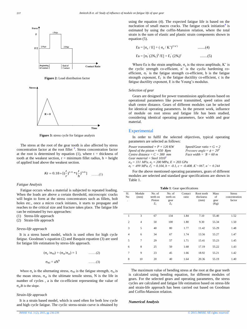
Effect of contact ratio
For smooth transmission of power, the contact ratio between
mating gears will be normally greater than ‘1’. i.e., For certain
period of the contact, two pairs of teeth will be sharing the load,
while for the remaining period, only one pair of teeth will be taking
the entire load. Fig. 2 illustrates typical load distribution2 during
contact period, for contact ratio between 1 & 2. Thus, by
considering the effects of moving tooth load and contact ratio, the
stresses at the tooth root will be fluctuating continuously from ‘0’
to maximum and to ‘0’, as indicated in Fig. 3.
(a)
(b)
Figure 1: (a) Gear Terminology (b) Moving Load
Amitesh.B et. al/ Study of influence of module on fatigue life of spur gear
JMSSE Vol. 3 (2), 2015, pp 236-239 © 2015 JMSSE All rights reserved
Figure 2: Load distribution factor
Figure 3: stress cycle for fatigue analysis
The stress at the root of the gear tooth is also affected by stress
concentration factor at the root fillet 3. Stress concentration factor
at the root is determined by equation (1), where t = thickness of
tooth at the weakest section, r = minimum fillet radius, h = height
of applied load above the weakest section.
])(*)[(18.0 45.015.0
h
t
r
tKt …….(1)
Fatigue Analysis
Fatigue occurs when a material is subjected to repeated loading.
When the loads are above a certain threshold, microscopic cracks
will begin to form at the stress concentrators such as fillets, bolt
holes etc., once a micro crack initiates, it starts to propagate and
reaches to the critical size and fracture takes place. The fatigue life
can be estimated by two approaches:
(1) Stress-life approach
(2) Strain-life approach
Stress-life approach
It is a stress based model, which is used often for high cycle
fatigue. Goodman’s equation (2) and Basquin equation (3) are used
for fatigue life estimation by stress-life approach.
(σa /σNf) + (σm/σut) = 1 …….(2)
σNf = aNb …….(3)
Where σa is the alternating stress, σNf is the fatigue strength, σm is
the mean stress, σut is the ultimate tensile stress, N is the life in
number of cycles , a is the co-efficient representing the value of
σa,B is the slope.
Strain-life approach
It is a strain based model, which is used often for both low cycle
and high cycle fatigue. The cyclic stress-strain curve is obtained by
using the equation (4). The expected fatigue life is based on the
nucleation of small macro cracks. The fatigue crack initiation4 is
estimated by using the coffin-Mansion relation, where the total
strain is the sum of elastic and plastic strain components shown in
equation (5).
Ɛa = [σa / E] + ( σa / K’)(1/n’) ........(4)
Ɛa = [σf’ (2Nf )
b /E] + Ɛf’ (2Nf)
c ........(5)
Where Ɛa is the strain amplitude, σa is the stress amplitude, K’ is
the cyclic strength co-efficient, n’ is the cyclic hardening co-
efficient, σf’ is the fatigue strength co-efficient, b is the fatigue
strength exponent, Ɛf’ is the fatigue ductility co-efficient, c is the
fatigue ductility exponent, E is the Young’s modulus.
Selection of gear
Gears are designed for power transmission applications based on
operational parameters like power transmitted, speed ratios and
shaft centre distance. Gears of different modules can be selected
for identical operating parameters. In the present work, influence
of module on root stress and fatigue life has been studied,
considering identical operating parameters, face width and gear
material.
Experimental
In order to fulfil the selected objectives, typical operating
parameters are selected as follows:
Power transmitted = P = 120 KW Speed/Gear ratio = G = 2
Speed of the pinion = 650 Rpm Pressure angle = ϕ = 200
Centre distance = C = 300 mm Face width = ‘B = 60 m Gear material = Steel 10105
σut = 331 MPa, σy = 200 MPa, E = 203 GPa
σf’ = 499 MPa, Ɛf
’ = 0.104, b = -0.1, c = -0.408, K’=867, n’ = 0.244
For the above mentioned operating parameters, gears of different
modules are selected and standard gear specifications are shown in
Table 1.
Table 1: Gear specifications
Sl.
No
.
Module
(mm)
No. of
teeth on
Pinion
Z1
No. of
teeth on
gear
Z2
Contact
ratio
Root tooth
thickness
(mm)
Mass
of
gear
(Kg)
Stress
concentration
factor
1 3 67 134 1.84 7.10 55.40 1.52
2 4 50 100 1.80 9.30 55.34 1.50
3 5 40 80 1.77 11.42 55.29 1.48
4 6 34 67 1.74 13.56 55.27 1.47
5 7 29 57 1.71 15.41 55.23 1.45
6 8 25 50 1.68 17.19 55.22 1.43
7 9 23 45 1.66 18.92 55.21 1.42
8 10 20 40 1.64 20.36 55.19 1.40
The maximum value of bending stress at the root at the gear teeth
is calculated using bending equation, for different modules of
gears. For the selected gears and operating parameters, the stress
cycles are calculated and fatigue life estimation based on stress-life
and strain-life approach has been carried out based on Goodman
and Coffin-Mansion relation.
Numerical Analysis
237

Amitesh.B et. al/ Study of influence of module on fatigue life of spur gear
JMSSE Vol. 3 (2), 2015, pp 236-239 © 2015 JMSSE All rights reserved
The stress analysis and fatigue life estimation of the selected
gears has also been carried out using FEA tool ANSYS.
The 3D model of spur gear is created in CATIA as shown in Fig.
4(a) and it is imported to ANSYS for the analysis. The hex
dominant mesh is applied to the model as shown in Fig. 4(b). The
boundary conditions are applied to the model i.e., the shaft hole is
fixed and the nodal force is applied on the gear tooth as shown in
Fig. 4(c). The model is solved for results and the equivalent stress
obtained at the root of the gear tooth is shown in Fig. 4(d).
Figure 4(a): Spur Gear Figure 4(b): Hex dominant mesh
Figure 4c): Nodal force Figure 4(d): Equivalent stress
The fatigue analysis is carried out by both stress-life and strain-
life approach. The stress-life approach is performed by using a
fatigue tool. The type of loading – zero based stress, Mean stress
theory – Goodman’s approach is selected, and the equivalent stress
is considered for the stress component, the alternating stress is
applied for the corresponding number of cycles The model is
solved for results and the life of the spur gear determined is shown
in Fig. 5.
The strain-life approach6-7 is performed by using a fatigue tool.
The type of loading – zero based stress, Mean stress theory –
Morrow’s approach is selected, and the equivalent stress is
considered for the stress component, The strain-life parameters like
fatigue strength co-efficient, fatigue strength exponent, fatigue
ductility co-efficient, fatigue ductility exponent is applied. The
model is solved for results and the life of the spur gear is
determined as shown in Fig. 6.
Figure 5: Life in number of cycles by Stress-life approach
Figure 6: Life in number of cycles by strain-life approach
Results and discussion
The results of the analysis carried out to study the influence of
module on the design aspects of the spur gears are discussed in the
following section. Fig. 7 shows the influence of module on the
stress concentration factors at the root of the gear teeth. It can be
observed that stress concentration factors decreases with increase
in module, which can be attributed to increase in fillet radius at the
root of the teeth, with increase in module.
Figure 7: Module versus Stress concentration factor
Figure 8 shows the variation of bending stress at the root of
the gear teeth, with module. The bending stress at the teeth root
can be observed to decrease with increase in module. This can be
attributed to increase in thickness of tooth at the root and decrease
in stress concentration factor, with increase in module of the gear.
The stress values obtained both analytically and numerically are
found to be in close tolerance with each other. It can also be
observed that the stress values become asymptotic at higher values
of module.
Figure 8: Module versus Root bending stress
238

Amitesh.B et. al/ Study of influence of module on fatigue life of spur gear
JMSSE Vol. 3 (2), 2015, pp 236-239 © 2015 JMSSE All rights reserved
Figure 9 indicates the stress based fatigue life of gears of
different modules, determined analytically as well as numerically.
It can be observed that fatigue life progressively increases with
increases with module and beyond 5mm, the life become infinite
for the operating conditions considered for the present study.
Stress–life estimation is somewhat conservative since it doesn’t
take into account, the ability of the material to withstand localized
plastic deformations.
Figure 9: Module versus Life in number of cycles
Figure 10 indicates the strain based fatigue life of gears of
different modules, determined analytically as well as numerically.
The fatigue life increases with module and become asymptotic at
higher values of module. Since the strain based approach
recognizes the ability of the material to undergo localised plastic
deformation without complete failure of the structure, the life
estimation is more pragmatic than the stress based approach.
Figure 10: Module versus Life in number of cycles
Figure 11 shows the variation of gear mass with change in
module. Moderate decrease in mass can be observed with increase
in module.
Figure 11: Module versus Mass of gear
Conclusion
Present work is a small attempt to study the influence of module
on design aspects of spur gears. Stress analysis and fatigue life
estimation has been carried out for typical operating conditions, by
varying the gear module. Results of the investigation indicate
reduction in mass, stress concentration factor and stresses at the
root of the teeth, with increase in gear module. Fatigue lives of the
gears are also found to increase with gear module. The result
obtained from analytical and numerical approaches are found to be
consistent with each other.
References
1. P. J. L. Fernandes (1996), Tooth Bending Fatigue Failures in
Gears. Engineering Failure analysis, Vol 3:219-225. 2. S.M.J.Ali et al. (2008) Load Sharing On Spur Gear Teeth And
Stress Analysis When Contact Ratio Changed 94-101.
3. Gitin M Maitra. (2001), Handbook of Gear Design, Tata McGraw –Hill Publishing company Limited, India.
4. J. Kramberger et al. (2002) Numerical calculation of bending
fatigue life of thin-rim spur gears, Engineering fracture mechanics 71: 647-656.
5. Ralph I. Stephens et al. (2001), Metal fatigue in engineering,
Wiley-Interscience publication. 6. D. Jelaska et al (2003) Numerical Modelling of Gear Tooth Root
Fatigue Behaviour, International Conference on Fatigue Crack
Paths. 7. J. Kramberger et al. (2004) Computational model for the analysis
of bending fatigue in gears, Computers and structures 82: 2261-
2269.
239