study of the perfection of the single crystal …
TRANSCRIPT

May 24th - 26th 2017, Brno, Czech Republic, EU
1924
STUDY OF THE PERFECTION OF THE SINGLE CRYSTAL PERMANENT MAGNETS OF THE
TICONAL 9 ALLOY
SIDOROV Evgeny1, AGAPOVA Elena2, GUNDAREV Vadim2
1Vladimir State University, Vladimir, Russian Federation, [email protected] 2Institute of Metal Physics of the Ural Department of the Russian Academy of Sciences, Ekaterinburg,
Russian Federation, [email protected]
Abstract
The aim of the present work was to improve the quality of the single crystal permanent magnets based on the
Ticonal 9 alloy (35 % Co, 14 % Ni, 7 % Al, 5 % Ti, 4 % Cu, Fe the rest, in wt.%) applied in the precision instruments of the space techniques. The alignment, configuration and structural perfection of the Ticonal 9
based single crystal magnets with different magnetic characteristics have been studied in the work. Single crystals grown of the melt by the directional controlled solidification method with the seed crystals having the
[001] alignment were used. Single crystals underwent standard heat-magnetic treatment (HMT) but had various parameters of the induction distribution on the poles. X-ray structure analysis and x-ray diffraction
topography allowed to study the crystal structure of the alloy after the HMT, to determine the lattice periods of the α- and α’-phases, to reveal two different pencil-like and plate-like configuration types. Small randomly
aligned crystals have been found. The single crystal structure was correlated to the induction distribution in the air gap on the magnet poles. The results of the study allowed improve the single crystal production
technique.
Keywords: Single crystal, permanent magnet, magnetic induction, lattice, phase
1. INTRODUCTION
Single crystals of metallic alloys have unique operation properties and are used in the most significant and
critical articles [1-4]. Single crystal ingots are used to manufacture single crystal permanent magnets for high precision instruments for the rocket and space techniques [4]. In Figure 1 a device with the single crystal
magnet of the Ticonal 9 alloy is shown.
Figure 1 General view of the single crystal magnets and the high precision device

May 24th - 26th 2017, Brno, Czech Republic, EU
1925
In the manufacturing process the induction distribution in the air gap Bδ (T) was controlled in finished single crystal permanent magnets, the relative difference of the inductions on the poles δBNS (%), deviation angle of
the matching mark from the heat-magnetic treatment (HMT) direction φ (deg), the maximums displacement angle ∆αNS (deg), distortion of the distribution curve configuration ∆B/ (%), asymmetry of the shape of the south
pole δB//S (%) and the north pole δB//
N (%) and the shape coefficient (KSH) were determined. If the controlled parameter values exceeded the specified values the manufactured magnets could not be used. In Table 1 the
controlled magnetic parameter values of 5 single crystal magnets of the Ticonal 9 alloy which were used in the present study are given. Magnets 1 and 5 met the required values completely. Magnets 2 - 4 didn’t meet the
technical requirements.
Table 1 Magnetic characteristics of the studied single crystal magnets
No. of the sample Bδ (T) δBNS (%) φ (deg) ∆αNS (deg) δB/ (%) δB//S (%) δB//
N (%) KSH (1)
1 0.637 2.34 0.5 0º 51’ 1.92 1.92 2.88 0.85
2 0.577 6.81 0.5 4º 30’ 2.85 4.76 6.66 0.81
3 0.645 2.67 0.5 6º 55’ 0 15.4 5.45 0.84
4 0.585 2.97 0.5 0º 1.96 12.7 12.9 0.83
5 0.593 1.1 0.5 0º 52’ 0.97 3.92 2.91 0.85
2. EXPERIMENTAL
Single crystal ingots of the Ticonal 9 alloy were grown by the directional controlled solidification method on the
seed crystals with the [001] alignment in the multi-position apparatus “Crystallizer 203” [4, 5]. The argon atmosphere was used to manufacture magnets. The temperature gradient in the melt in front of the crystallization front was GL= 6-8 K/mm. The growing rate was R = 1-1.5 mm/min. The diameter of the grown
single crystals was 22 mm.
Single crystal ingots underwent standard HMT. It consisted of the heating to the temperature 1250 °C and homogenizing at this temperature 20 - 25 min, cooling from 1250 °C to 800 °C at the rate no less than 150
K/min. Then the ingots were placed into the isothermal bath at the temperature 795 ± 5 °C for 10 min with the applied magnetic field H = 240 kA/m along the crystallographic direction [001]. The HMT was ended with the
two-step tempering: 5 h at 640 °C and 20 h at 560 °C. The surfaces of the selected magnets perpendicular to the growing direction [100] and their sections along the planes (001), (010) and (110) were ground and polished
with electrolyte to remove deformed layers. Light microscope “Neophot - 2” was used to study the longitudinal sections.
To study the crystal structure of the magnets a number of the X-ray structure analytical methods were applied: the Laue reflection method, the topographic angular scanning, Berg-Barrett methods, and the X-ray
diffractometry. The epigrams were taken in the Mo-emission with the apparatus УРС-60 in the chamber РКСО. The topographic and diffractometric investigations were carried out in the Co- and Cu-emissions using the
apparatus ДРОН-1 with the specially designed attachment. The distance from the source to the sample along the falling beam was 180 mm. The angular scanning topograms were taken in the (200), (002) and (220)
reflections; the Berg-Barrett topograms in the (220) reflection. The distance A from the sample to the film along the reflected beam was 5 mm in the Berg-Barrett method, it varied from 10 to 80 mm when the topograms
were taken by the angular scanning method. The reflection curves were obtained with the diffractometer in the (200) reflection when the samples were scanned in the angular disalignment period of the single crystals. The
presence of the extra crystallites in the magnets was tested by means of the reflection curves in the (200) reflection obtained for a wide range of the scanning angles of the samples. In this case a more rigid operation
mode of the apparatus and a swifter rotation of the sample in its own plane were applied. To determine the
May 24th - 26th 2017, Brno, Czech Republic, EU
1926
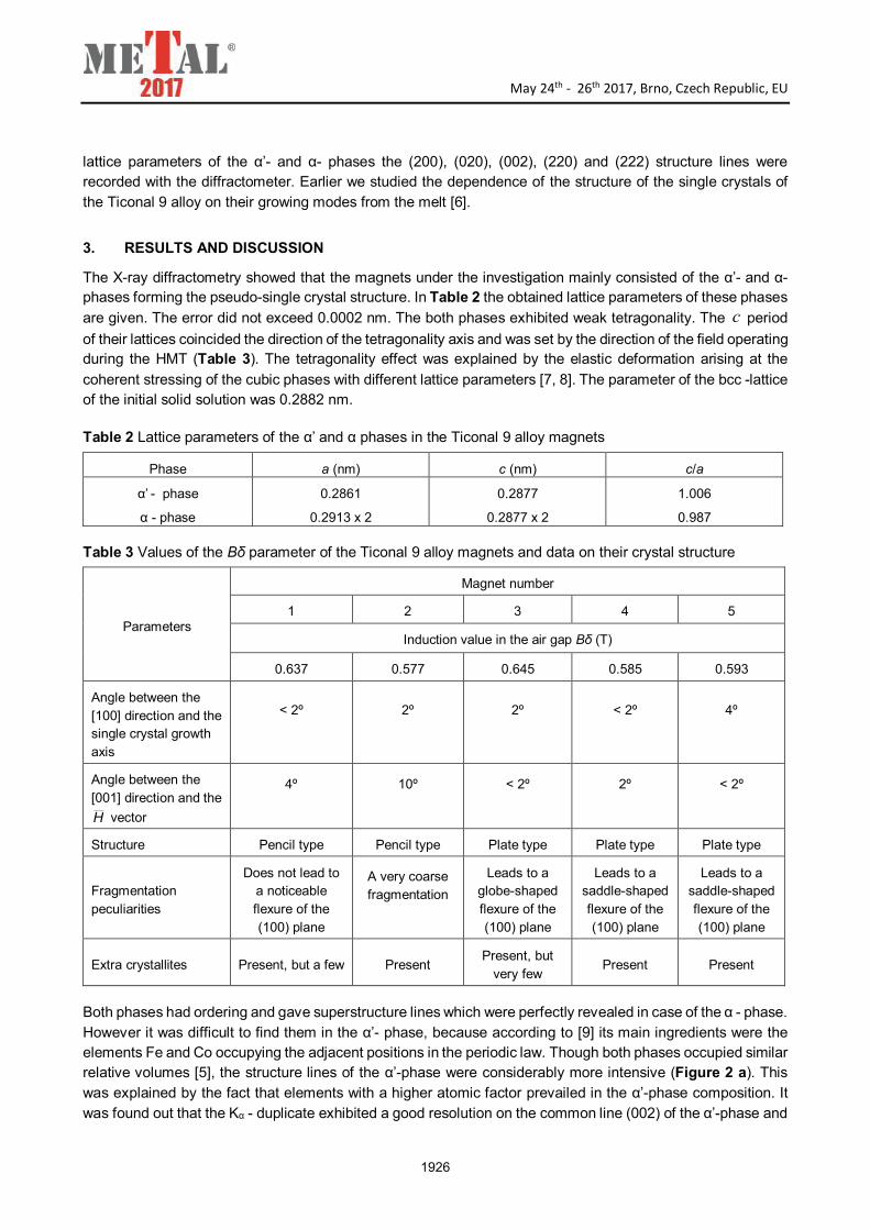
lattice parameters of the α’- and α- phases the (200), (020), (002), (220) and (222) structure lines were recorded with the diffractometer. Earlier we studied the dependence of the structure of the single crystals of
the Ticonal 9 alloy on their growing modes from the melt [6].
3. RESULTS AND DISCUSSION
The X-ray diffractometry showed that the magnets under the investigation mainly consisted of the α’- and α-phases forming the pseudo-single crystal structure. In Table 2 the obtained lattice parameters of these phases
are given. The error did not exceed 0.0002 nm. The both phases exhibited weak tetragonality. The period
of their lattices coincided the direction of the tetragonality axis and was set by the direction of the field operating during the HMT (Table 3). The tetragonality effect was explained by the elastic deformation arising at the
coherent stressing of the cubic phases with different lattice parameters [7, 8]. The parameter of the bcc -lattice of the initial solid solution was 0.2882 nm.
Table 2 Lattice parameters of the α’ and α phases in the Ticonal 9 alloy magnets
Phase a (nm) c (nm) c/a
α’ - phase
α - phase
0.2861
0.2913 x 2
0.2877
0.2877 x 2
1.006
0.987
Table 3 Values of the Bδ parameter of the Ticonal 9 alloy magnets and data on their crystal structure
Parameters
Magnet number
1 2 3 4 5
Induction value in the air gap Bδ (T)
0.637 0.577 0.645 0.585 0.593
Angle between the [100] direction and the single crystal growth axis
< 2º
2º
2º
< 2º
4º
Angle between the [001] direction and the
H vector
4º
10º
< 2º
2º
< 2º
Structure Pencil type Pencil type Plate type Plate type Plate type
Fragmentation peculiarities
Does not lead to a noticeable flexure of the (100) plane
A very coarse fragmentation
Leads to a globe-shaped flexure of the (100) plane
Leads to a saddle-shaped flexure of the (100) plane
Leads to a saddle-shaped flexure of the (100) plane
Extra crystallites Present, but a few Present Present, but
very few Present Present
Both phases had ordering and gave superstructure lines which were perfectly revealed in case of the α - phase.
However it was difficult to find them in the α’- phase, because according to [9] its main ingredients were the elements Fe and Co occupying the adjacent positions in the periodic law. Though both phases occupied similar relative volumes [5], the structure lines of the α’-phase were considerably more intensive (Figure 2 a). This
was explained by the fact that elements with a higher atomic factor prevailed in the α’-phase composition. It
was found out that the Kα - duplicate exhibited a good resolution on the common line (002) of the α’-phase and
c

May 24th - 26th 2017, Brno, Czech Republic, EU
1927
(004) of the α-phase, whereas the lines (200), (020) of the α’-phase and (400), (040) of the α-phase were strongly washed away (Figure 2). This confirmed the crystallographic alignment of the precipitate particles in
the direction of the field vector H and their strong shape anisotropy. According to [10] in the Ticonal 9 alloy
after the HMT the relation of the particle length to the width was 13-16 at their width 3·10-6 cm. The obtained
results, as far as the crystal family, crystallographic alignment of the lattices of the α’- and α-phases and their ordering were concerned, agreed with the data published earlier [5, 7, 10].
Figure 2 Diffraction lines of magnet 5
(a) (200) of the α’-phase (left), (400) of the α-phase (right); (b) Kα - duplicate (002) of the α/-phase and
(004) of the α-phase; the following range of the calculation rate was used: (a) 2·103 pulse/s, (b) 1·104 pulse/s
Let’s proceed to the description of the crystal structure of the magnets. Data about their alignment relative to the single crystal growing axis and the field tension vector H at the HMT were obtained by the Laue method
and were restricted to a small central region of the samples. The crystallographic direction [100] noticeably deviated from the growth axis only in magnet 5 (Table 3). A considerable deviation of the tetragonality axis
[001] from the direction of the vector H was found out for magnet 2 (Table 3).
By the topograms, obtained by the Berg-Barrett and the angular scanning methods, it was determined that in
magnets 1 and 2 the dendrite cells form the pencil-like structure and magnets 3, 4, 5 had a plate-like prismatic
configuration (Figure 3). The plates were parallel to the crystallographic planes (011) and (011). Using the
topograms, the distances along the directions [001] and [010] between the dendrite cells in magnet 1 and
between the plates in magnet 3 were determined. This period coincided for the dendrite cells and plates, it was 0.38 mm. The metallographic study of the longitudinal sections of the magnets with the plate type structure
showed the presence of the titanium monosulfide inclusions. Weak lines of this compound were detected in the diffractograms of the magnets. The morphology of the TiS inclusions was similar to the one described for
the Ticonal 9 alloy single crystals alloyed with sulfur [11]. Broken eutectic cells were present with the TiS phase as the eutectic constituent between the dendrite cells of the α-solid solution. Plates were formed during the
single crystal growing process by the combination of the dendrite cells [11].
Analysis of the angular scanning topograms obtained in the (220), (200) and (002) reflections and the (200)
reflection curves showed that all magnets had a developed substructure. Special attention should be paid to magnet 2 possessing a very coarse fragmentation (Figure 3 b). In this magnet the disalignment between the
fragments reached 10º. To estimate quantitatively the perfection we chose magnets 1 and 3 containing a few random crystallites, which will be discussed below.

May 24th - 26th 2017, Brno, Czech Republic, EU
1928
Figure 3 X-ray topograms (x 1.5) of magnets 1 (a), 2 (b), 3 (c), 4 (d), 5 (e) obtained by the angular
scanning method in the reflection (220) at A = 10 mm
The characteristics of the substructure of the I order were the following: the average transverse dimension of the fragments was 1.0 mm; the average disalignment angle between them was 15/; the range of the dispersion of the [100] alignment was 4.5º. It must be noted that the perfection of the substructure of the single crystals grown in the multi - position apparatus “Crystallizer 203” deteriorated in comparison with the single crystals grown in the one-position apparatus “Crystal EM” and described in the work [6]. The dispersion range of the set alignment increased considerably. To study the dispersion character of the [100] alignment in the magnets we compared the angular scanning topograms in the reflections (200) and ( 002 ) recorded on their top and
bottom bases. For magnet 1 the image areas of the both bases were approximately the same. For magnet 3 the image area of the bottom base surpassed the image area of the top base. Accordingly, the angular width
of the reflection curve in the reflection ( 002 ) exceeded that of the reflection (200) (Figure 4).
Figure 4 Reflection curves of magnet 3 in the reflections (200) (a) and ( 002 ) (b) obtained with the
horizontal slot in front of the sample 0.15 mm

May 24th - 26th 2017, Brno, Czech Republic, EU
1929
Earlier it was found out [6] that the image areas in the topograms of the adjacent cross-sections of the single crystals of the Ticonal 9 alloy differed. In the work [12] it was shown that these peculiarities of the diffraction
images in the reflections (200) and ( 002 ) were the result of the monotonous change of the fragment alignment
at the moving from the single crystal axis in the radial direction with the formation of the macroscopic flexure
(globe-shaped bending) of the transverse plane (100). It was determined that the flexure direction of the plane (100) and the growth front coincided. Obviously, this structure imperfection of the single crystal was retained
during its HMT.
The image transformations in the topograms at the transition from the top to the bottom base of magnets 4
and 5 indicated a more complicated macroscopic flexure of the plane (100), namely the saddle-shaped flexure. Really, the reflection from one base was contracted in the azimuth direction and stretched in the radial, and from the opposite one it was contracted in the radial direction and stretched in the azimuth (Figure 5). We
believe that the macroflexure of the transversal plane (100) of the single crystal depends on the location of its
mold in the growing apparatus, since it is difficult to apply identical thermal field for all positions.
Figure 5 X-ray topograms (x 2) of magnet 4 obtained by the angular scanning method at A = 80 mm in the
reflection (200) (a) and the reflection ( 002 ) (b). The radial and azimuth directions in the topograms
correspond to the [001] and [010] directions of the pseudo-single crystal
It was important to find out if there were extra crystallites called “random” in the magnets. On the reflection
curves of all magnets obtained in the reflection (200) for a wide region of the angular positions of the plane (100) weak “extra” reflections were detected. They were located outside the angular period of the reflection curve of the main pseudo-single crystal (Figure 6). These reflections belonged to extra crystallites with the
alignment differing from the set alignment [100]. Comparison of the “expanded” reflection curves showed that
extra crystallites occupied a more considerable volume in magnets 2, 4, 5, their volume fraction was less in magnets 1 and 3 (Table 3). Magnet 3 contained the least amount of the extra crystallites and their reflections
were located close to the reflection of the main pseudo-single crystal. Based on the data of Tables 1 and 3 we
can say that the induction characteristics in the air gap depend first of all on the magnet volume fraction
occupied by the extra crystallites. However, magnet 2 exhibited the lowest values of the controlled parameters; besides the structure imperfection in the form of the extra crystallites, it had a very coarse fragmentation. We
must note that in magnets 1 and 3 with satisfactory parameter values fragmentation either did not lead to a noticeable flexure of the crystallographic plane (100) or its simple bending flexure was realized.

May 24th - 26th 2017, Brno, Czech Republic, EU
1930
Figure 6 Reflection curves of magnet 2 in the reflection (200) obtained from the pseudo-single crystal (a)
and from the extra crystallites (b) when the total plane of the sample is illuminated by the X-rays
4. CONCLUSION
1) The studied Ticonal 9 alloy magnets were pseudo-single crystals consisting of the precipitates of the α’-phase (a = 0.2861 nm; c = 0.2877 nm) and α-phase (a = 0.2913 x 2 nm; c = 0.2877 x 2 nm). The
presence of the ordering of these phases, weak tetragonality of their lattices, shape anisotropy of the
precipitates with the crystallographic directions was confirmed, which corresponds to the high coercivity of the alloy.
2) The magnets had pencil- or plate-shaped structure of the growth origin. They inherited also a developed substructure, with which the dispersion of the set alignment [100] and the macroscopic flexure of the
transversal plane were related. According to the results of the analyses, in the magnets with the satisfactory values of the induction distribution in the air gap the angular period of the dispersion of the
alignment [100] was 4.5º. 3) The magnets contained some amount of extra crystallites with the alignment different from the set {100}.
Their presence was detected by the “expanded” reflection curves. The relative volume fraction of the
extra crystallites was higher in the magnets rejected by the technical parameters. 4) The use of the multi-position apparatus for the single crystal growing instead of the one-position resulted
in the deterioration of their substructure perfection up to the coarse fragmentation which had a negative effect on the technical parameters of the magnet.
REFERENCES
[1] ШАЛИН, Р. С., СВЕТЛОВ, И. Л., КАЧАНОВ, Е. Б. Монокристаллы никелевых жаропрочных сплавов. Москва: Машиностроение, 1997, 334 p.
[2] КАБЛОВ, Е. Н. Литые лопатки газотурбинных двигателей: Сплавы, технологии, покрытия. Москва: МИСиС, 2001, 631 p.
[3] LAPIN, J. The Effect of microstructure on mechanical properties of single crystal CMSX-4 superalloy. In METAL
2013: 22nd International Conference on Metallurgy and Materials. Ostrava: TANGER, 2013, on CD-ROM.
[4] СИДОРОВ, Е. В. Отливки магнитов с монокристаллической и столбчатой структурами. Теория и
практика изготовления. Владимир: Транзит, 2007, 165 p.
[5] СЕРГЕЕВ, В. В., БУЛЫГИНА, Т. И. Магнитотвердые материалы. Москва: Энергия, 1980, 224 p.
[6] АГАПОВА, Е. В., ГУНДЫРЕВ, В. М., СИДОРОВ, Е. В. Исследование структуры слитков сплава ЮНДК35Т5АА. Металлы, 1993, no. 2, pp.136-140.

May 24th - 26th 2017, Brno, Czech Republic, EU
1931
[7] ЛИВШИЦ, Б. Г., ЛИНЕЦКИЙ, Я. Л. Исследование кристаллического строения метастабильных фаз в сплаве тикональ. ДАН СССР, 1966, vol. 170, no. 3, pp. 554-556.
[8] ХАЧАТУРЯН, А. Г. Теория фазовых превращений и структура твердых растворов. Москва: Наука, 1974. 384 p.
[9] ГРАНОВСКИЙ, Е. Б., ФРИДМАН, А. А., ПОВИЦКИЙ, В. А., ПАШКОВ, П. П. О составе низкотемпературных фаз сплава тикональ. Труды ВНИИЭМ, 1971, vol. 35, pp. 91-95.
[10] ГРАНОВСКИЙ, Е. Б., ПАШКОВ, П. П., СЕРГЕЕВ, В. В., ФРИДМАН, А. А. Структура и свойства сплавов Fe-Co-Ni-Al-Cu в высококоэрцитивном состоянии. ФММ, 1967, vol. 23, no. 3, pp. 444-448.
[11] АГАПОВА, Е. В., СИДОРОВ, Е. В. Формирование плитообразной структуры в монокристаллах магнитного сплава ЮНДКТ. ФММ, 1994, no. 5, pp. 155-161.
[12] АГАПОВА, Е. В., СИДОРОВ, Е. В., ГУНДЫРЕВ, В. М. Дисперсия рассеяния кристаллографических ориентировок в монокристаллах магнитотвердых сплавов, полученных из расплава. Материаловедение, 2002, no. 8, pp. 53-56.