study on private-initiative … on private-initiative infrastructure projects in developing...
TRANSCRIPT

STUDY ON PRIVATE-INITIATIVE INFRASTRUCTURE PROJECTS IN DEVELOPING COUNTRIES IN FY2010
STUDY ON RING ROAD NO. 4 PROJECT (TRUNG GIA – PHUNG SECTION)
IN THE SOCIALIST REPUBLIC OF VIETNAM
FINAL REPORT
March 2011
Prepared for: The Ministry of Economy, Trade and Industry
Prepared by: Ernst & Young ShinNihon LLC
Japan External Trade Organization (JETRO) Nippon Engineering Consultants Co., Ltd.
Central Nippon Expressway Co., Ltd. Nippon Steel Topy Bridge Co., Ltd.
Shimizu Corporation


Preface
This report constitutes the summarized results of the “Study on Private-Initiative Infrastructure Projects in Developing Countries in FY2010” which was entrusted by Ernst Young ShinNihon LLC to Nippon Engineering Consultants Co., Ltd., Central Nippon Expressway Co., Ltd., Nippon Steel Topy Bridge Co., Ltd., Shimizu Corporation. The “Study on Ring Road No. 4 Project (Trung Gia– Phung Section) in the Socialist Republic of Vietnam” aims to survey the feasibility of the Project on Trung Gia – Phung Section of Ring Road No. 4 in Hanoi by PPP Scheme. We hope this report will be helpful in realizing the Project and serve as a useful reference to all concerned parties in Japan.
March 2011
Nippon Engineering Consultants Co., Ltd. Central Nippon Expressway Co., Ltd.
Nippon Steel Topy Bridge Co., Ltd. Shimizu Corporation


Social Republic of Vietnam Hanoi City
Project Location Map
Start Point of the Study(Crossing with the Hanoi-Thai Nguyen Expressway)
Hanoi-Lao Cai Expressway
NH.2
NH.32
NH.6
NH
.1
NH.5
New
NH.1
NH.1
NH.18
NH
.3Hanoi-Thai Nguyen
Expressway
RR-4(N
orth
-wes
t Sec
tion)
Lang-Hoa Lac Road
New
NH
.1
Crossing with theHanoi-Lao Cal Expressway Bac Giang
Thai Nguyen
Hanoi
Bac Ninh
Hung Yen
Vinh Phuc
RR
-3 RR-2
Noi BaiInternational
Airport
Hai Phong→
Trung Gia
Phung
End Point of the Study(Crossing with the NH.32)
Hong Ha Bridge
NH.23
0 5 10km
Hanoi


ABBREVIATIONS
ASEAN Association of Southeast Asian Nations ODA Official Development Assistance
BMS Bridge Management System OR Operations Research
BOD Biochemical Oxygen Demand PC Pre-stressed Concrete
BOT Build, Operation & Transfer PCU Passenger Car Unit
BT Build, Transfer PE Polyethylene
CDL Chart Datum Level PMU2 Project Management Unit 2
CDM Clean Development Mechanism PPP Public Private Partnership
DD, D/D Detailed Design PRs Provincial Roads
EIA Environmental Impact Assessment PVD Plastic Vertical Drain
ETC Electronic Toll Collection QC Quality Control
EU European Union RC Reinforced Concrete
FS, F/S Feasibility Study RMS Road management System
GDP Gross Domestic Production S/V Supervision
HAPI Hanoi Authority of Planning & Investment SD Sand Drain
HPC Hanoi People’s Committee SDP Suspended Dust Particle
IC Interchange SPC Special Purpose Company
IE Industrial Engineering TEDI Transport Engineering Design Incorporated
IEE Initial Environmental Examination VGF Viability Gap Funding
IMF International Monetary Fund VND Vietnam Dong
JBIC Japan Bank for International Cooperation VSA Vietnam Steel Association
JETRO Japan External Trading Organization WTO World Trade Organization
JICA Japan International Cooperation Agency
JV Joint Venture
LCC Life Cycle Cost
LSD Land Survey Datum
MARD Ministry of Agriculture and Rural Development
MONRE Ministry of Natural Resources & Environment
MOT Ministry of Transport
MPI Ministry of Planning & Investment
NH National Highways
O&M Operation & Maintenance


i
Table of Contents Preface Project Site Map Abbreviations Executive Summary Chapter 1 Overview of the Host County and Sector.....................................................1- 1
1.1 Economic and Financial Conditions .......................................................................1- 1 1.1.1 Economic Conditions .................................................................................................................1- 1 1.1.2 Industrial Structure .....................................................................................................................1- 2 1.1.3 Foreign Trade .............................................................................................................................1- 3 1.1.4 Investments.................................................................................................................................1- 3 1.1.5 National Finance ........................................................................................................................1- 5
1.2 Overview of Relevant Sectors.................................................................................1- 6 1.2.1 Modes of Transport ....................................................................................................................1- 6 1.2.2 Road Sector ................................................................................................................................1- 7 1.2.3 Railroad Sector...........................................................................................................................1- 8 1.2.4 Port Sector ..................................................................................................................................1- 9 1.2.5 Hanoi Ring Road Master Plan...................................................................................................1-11 1.2.6 Construction Plan for Hanoi Ring Road 4.................................................................................1-11 1.2.7 The rail network centered on Hanoi ..........................................................................................1-12
1.3 Situation in the target area......................................................................................1-13 1.3.1 Social condition of the target area .............................................................................................1-13 1.3.2 Natural conditions in the target area..........................................................................................1-14 1.3.3 Economy of the target area........................................................................................................1-14 1.3.4 Key Development Plans ............................................................................................................1-17
Chapter 2 Study Methodology.........................................................................................2- 1
2.1 Details of Survey.....................................................................................................2- 1 2.2 Survey Organization................................................................................................2- 2 2.3 Study Method ..........................................................................................................2- 3
2.3.1 Project Plan ................................................................................................................................2- 3 2.3.2 Traffic Demand Forecasts ..........................................................................................................2- 3 2.3.3 Road Plans..................................................................................................................................2- 3 2.3.4 Bridge Plans ...............................................................................................................................2- 3 2.3.5 Construction Plans and Cost Estimation ....................................................................................2- 4 2.3.6 Studies of Environmental and Social Aspects ............................................................................2- 4
2.4 Study Schedule ........................................................................................................2- 5 2.4.1 Overview ....................................................................................................................................2- 5 2.4.2 Field Survey ...............................................................................................................................2- 6 2.4.3 Domestic Survey ........................................................................................................................2- 7 2.4.4 Debriefing Session .....................................................................................................................2- 7

ii
Chapter 3 Justification, Objectives and Technical Feasibility of the Project .............3- 1 3.1. Background and necessity.......................................................................................3- 1
3.1.1. Project background.....................................................................................................................3- 1 3.1.2. Project necessity.........................................................................................................................3- 1 3.1.3. Comparison between the proposed project and alternatives.......................................................3- 2
3.2 Examination Necessary for Defining Project Content ............................................3- 4 3.2.1 Existing Reports .........................................................................................................................3- 4 3.2.2 Traffic demand forecast..............................................................................................................3- 7 3.2.3 Analysis on Obstacle for the Project .........................................................................................3-14 (1) Route Study ...............................................................................................................................3-14 (2) Topography and geology ...........................................................................................................3-20 (3) River and hydrological study ....................................................................................................3-21 (4) Other natural condition..............................................................................................................3-25 3.2.4 Examination on technical method .............................................................................................3-28
3.3 Outline of the Project .............................................................................................3-76 3.3.1 Basic Policy for Defining Project..............................................................................................3-76 3.3.2 Concept Design and the Use of Appropriate Equipment...........................................................3-81 3.3.3 Project Cost ...............................................................................................................................3-88
Chapter 4 Evaluation of Environmental and Social Aspects........................................4- 1
4.1. Analysis of the current conditions from environmental and social aspects ............4- 1 4.1.1. Analysis of the current conditions..............................................................................................4- 1 4.1.2. Future forecast (without Project)................................................................................................4- 5
4.2. Environmental improvement effects associated with implementation of the project4-6 4.2.1. Natural and living environments ................................................................................................4- 6 4.2.2. Social environment.....................................................................................................................4- 8
4.3. Impact of the project from environmental and social aspects .................................4- 9 4.3.1. Impact of construction and operation of the project on environmental and social aspects ........4- 9 4.3.2. Comparison between the proposed project and other options with less environmental impact 4-14 4.3.3. Discussions with the implementing agency and collecting information local experts ..............4-14
4.4. Overview of the environment- and society-friendly laws and regulations in the partner country ......................................................................................................4-16
4.4.1. Overview of environment- and society-friendly laws and regulations related to the implementation of the project .........................................................................................................4-16
4.4.2. Details of EIA, etc. of the partner country required to implement the project ..........................4-19 4.5. What the Vietnam government should implement to realize the project ...............4-21
4.5.1. Completion of an EIA report .....................................................................................................4-21 4.5.2. Discussion with local residents .................................................................................................4-21
Chapter 5 Financial and Economic Evaluation.............................................................5- 1
5.1 Project Cost .............................................................................................................5- 1 5.2 Outline of the Result of Preliminary Financial and Economic Analysis.................5- 4
5.2.1 Calculation basis for FIRR.........................................................................................................5- 4 5.2.2 Case setting to be analyzed in PPP scheme for implementing construction project...................5- 5 5.2.3 Result of preliminary financial analysis .....................................................................................5- 7 5.2.4 Result of calculation of Economical Internal Rate of Return(EIRR)...................................5-19

iii
Chapter 6 Planned Project Schedule ..............................................................................6- 1 Chapter 7 Implementing Organization ..........................................................................7- 1
7.1 Overview of Implementation Agency in Partner Country ......................................7- 1 7.2 Organizational Structure for Project Implementation in Partner Country...............7- 3
Chapter 8 Technical Advantages of Japanese Companies............................................8- 1
8.1 Expected Forms of Participation by Japanese Companies......................................8- 1 8.2 The advantages afforded by Japanese technologies ................................................8- 3 8.3 Measures Necessary to Enhance Competitiveness of Japanese Companies ..........8-10
8.3.1 Systems to Subsidize Costs Required for Participation in International Competitive Bids .......8-10 8.3.2 Funds for Bidding Expense Subsidy System..............................................................................8-11
8.4 Japanese Company’s Image in the Special Purpose Company established in Vietnam .........................................................................................................................8-12
Chapter 9 Financial Outlook...........................................................................................9- 1
9.1 Examination on Funding Resource and Financing Plan .........................................9- 1 9.2 Feasibility of Financing...........................................................................................9- 2 9.3 Analysis of Cash Flow ............................................................................................9- 3
9.3.1 Precondition ...............................................................................................................................9- 3 9.3.2 Result of Case Flow ...................................................................................................................9- 5
Chapter 10 Action Plans and Issues for PPP Projects ..................................................10- 1
10.1. The situation regarding implementation of this project ........................................10- 1 10.2. Measures which will be necessary for the implementation of this project ...........10- 2
10.2.1. Investment in the Vietnamese government’s VGF ...........................................................10- 2 10.2.2. The establishment of objective assessment criteria for international competitive tendering on
the Vietnamese side ....................................................................................................................10- 2 10.2.3. Flexible application of BT and BOT schemes..................................................................10- 3 10.2.4. Toll policy, taking other road tolls into account ...............................................................10- 3 10.2.5. Measure for Delay of land acquisition .............................................................................10- 4
10.3. Specific Action Plan and Issues for the Implementation of This Project..............10- 5 10.3.1. Action Plan and Issues on the Vietnamese Side ...............................................................10- 5 10.3.2. Action Plan and Issues on the Japanese Side ...................................................................10- 6
10.4. Results of the PPP Project Fact-finding Survey in Viet Nam ...............................10- 7 10.4.1. BITEXCO (Binh Minh Production Management and Import/Export Company), Hanoi
Office ..........................................................................................................................................10- 7 10.4.2. VINACONEX (Vietnam Construction and Import-Export Joint Stock Corporation), Ha Noi
Headquarters ..................................................................................................................................10- 9 10.4.3. Him Lam Corporation Hanoi Branch ..............................................................................10-10
Appendices
Appendix A: Minutes of Discussion Appendix B: Minutes of Discussion with local Environmental Consultant Appendix C: Photos on the Project Site

iv
Figure 1-1 GDP Growth in Viet Nam.................................................................................................... 1- 2 Figure 1-2 New Urban zone North An Khanh....................................................................................... 1-17 Figure 1-3 Van Giang tourism-trading urban zone................................................................................ 1-18 Figure 1-4 Tu Son Town - Bac Ninh Province ...................................................................................... 1-19 Figure 1-5 Hoa Lac Hi-tech zone .......................................................................................................... 1-20 Figure 1-6 Quang Minh IZ .................................................................................................................... 1-20 Figure 1-7 Pho Noi IZ ........................................................................................................................... 1-21 Figure 1-8 Que Vo IZ ............................................................................................................................ 1-22 Figure 2-1 Flow Chart of Survey .......................................................................................................... 2- 1 Figure 2-2 Structure of the Study Team ................................................................................................ 2- 2 Figure 3-1 Location of Traffic Survey................................................................................................... 3- 7 Figure 3-2 Route Outline........................................................................................................................3-15 Figure 3-3 (a) Route Survey......................................................................................................................3-18 Figure 3-3 (b) Route Survey......................................................................................................................3-19 Figure 3-4 Diagram of Relation between Water level and Discharge of Hong Ha Bridge.....................3-23 Figure 3-5 Hong Ha Bridge’s location and alignment in the aerial map ................................................3-32 Figure 3-6 Options for Hong Ha Bridge ................................................................................................3-36 Figure 3-7 Cross Section of PC Box Girder...........................................................................................3-36 Figure 3-8 Cross Section for Cable-Stayed Bridge ................................................................................3-38 Figure 3-9 Guideline for unpainted use of weathering steel ..................................................................3-39 Figure 3-10 Concept of Relation between Time and Rust Developing ................................................3-40 Figure 3-11 Photo samples for estimating status of rust developed .......................................................3-40 Figure 3-12 Cross Section for Extradosed Bridge..................................................................................3-41 Figure 3-13 An Example of Cantilever Erection Method ......................................................................3-41 Figure 3-14 An Example of Large-Scale Segment Block ......................................................................3-41 Figure 3-15 Concept of PC Box girder Bridge with Corrugated Steel Web Plate..................................3-42 Figure 3-16 Concept for Steel Pipe Sheet Pile Foundation ....................................................................3-44 Figure 3-17 Cross Section for the Approach Bridge(Super T shaped PC bridge) ..................................3-45 Figure 3-18 Cross Section for the Approach Bridge (Portion of the crossing dyke)..............................3-45 Figure 3-19 Steel pipe pile foundations..................................................................................................3-50 Figure 3-20 Steel pipe piles for temporary enclosure on the Thanh Tri Bridge .....................................3-50 Figure 3-21 PC Box Girder Erection Procedure.....................................................................................3-51 Figure 3-22 Example of Erection of a Steel Cable-stayed Bridge (Nhat Tan Bridge)............................3-51 Figure 3-23 An Example of Extradosed Bridge Construction ...............................................................3-52 Figure 3-24 Total Frame of RMS ...........................................................................................................3-64 Figure 3-25 The BMS Concept ..............................................................................................................3-68 Figure 3-26 Road transverse sectional composition (expressway, urban zone) .....................................3-81 Figure 3-27 Road Transverse Sectional Composition (Expressway, Non-urban Zone) .........................3-82 Figure 3-28 Road Width Configuration (highway, general section).......................................................3-82 Figure 3-29 Transverse Sectional Composition (highway, residential zone) .........................................3-83 Figure 3-30 Cross section of bridge in main line ...................................................................................3-85 Figure 3-31 Bridge cross section for urban road bridge.........................................................................3-85 Figure 3-32 Cross section of the viaduct for main line ..........................................................................3-86 Figure 3-33 Bridge cross section for section 3.......................................................................................3-87

v
Figure 3-34 Cross section for the Hong Ha bridge.................................................................................3-87 Figure 4-1 BOD(mg/ 1) ................................................................................................................... 4- 1 Figure 4-2 NH4(mg/ l) ..................................................................................................................... 4- 1 Figure 4-3 CO(μg/m3) ................................................................................................................... 4- 4 Figure 4-4 NO2(μg/m3) ................................................................................................................. 4- 4 Figure 4-5 SO2(μg/m3).................................................................................................................. 4- 4 Figure 4-6 Formula to calculate CO2 emissions by motor vehicles...................................................... 4- 6 Figure 4-7 Original unit of emission and travel speed .......................................................................... 4- 7 Figure 4-8 Flow for analyzing emission of CO2................................................................................... 4- 8 Figure 5-1 Indexes of lending interest rate, inflation rate etc., in Vietnam ........................................... 5- 4 Figure 5-2 Studied Section .................................................................................................................... 5- 5 Figure 5-3 Comparing Time and Distance with and without RR4 ........................................................ 5- 5 Figure 7-1 Organizational Structure of the Hanoi People’s Committee ............................................. 7- 2 Figure 7-2 Organizational Structure for PPP Projects ........................................................................... 7- 3 Figure 8-1 Schematic view of steel pipe sheet pile foundation............................................................. 8- 5 Figure 8-2 Yearly Construction of Steel Pipe Sheet Pile Foundations .................................................. 8- 6 Figure 8-3 Mihara Bridge...................................................................................................................... 8- 6 Figure 8-4 Prefabricated Parallel Wire Strand and Indented Surface Treatment................................... 8- 7 Figure 8-5 Trend of Weather Resistant Steel......................................................................................... 8- 9 Figure 8-6 Project Implementation System in Case 5 ........................................................................... 8-13 Figure 8-7 Project Implementation system under PPP scheme as usual ............................................... 8-14 Figure 9-1 Assumed Project Scheme .................................................................................................... 9-3 Figure 9-2 Financing method (case 2)................................................................................................... 9-4

vi
Table 1-1 Industrial Composition in Vietnam (%) ................................................................................ 1- 2 Table 1-2 Exports and Imports of Vietnam (million USD) ................................................................... 1- 3 Table 1-3 Trading Partners: 2005 (million USD) .................................................................................. 1- 3 Table 1-4 Investment Trends (‘00 million Yen)..................................................................................... 1- 4 Table 1-5 Investment Trends (trillion VND) ......................................................................................... 1- 4 Table 1-6 Foreign Direct Investment (Approval Basis) by Region (‘000 Yen) .................................. 1- 5 Table 1-7 National Budget Trends (trillion VND)................................................................................. 1- 5 Table 1-8 Passenger Transport: Modal Split and Growth...................................................................... 1- 6 Table 1-9 Cargo Transport: Modal Split and Growth............................................................................ 1- 6 Table 1-10 Total Extension and Density of Roads in Vietnam: 2006.................................................... 1- 7 Table 1-11 Expressway Routes to be Developed over the Short Term (2006 – 2015) ........................ 1- 8 Table 1-12 Main Railroad Lines: Extension and Track Gauge.............................................................. 1- 9 Table 1-13 Major Port Complexes in Vietnam...................................................................................... 1-10 Table 1-14 Economic Growth and GDP of the Target Area and the Country........................................ 1-15 Table 1-15 Production Value From Each Segment of Economic Structure in the Survey Target Area . 1-16 Table 1-16 Power Projects up to 2025................................................................................................... 1-23 Table 2-1 Overall Survey Schedule....................................................................................................... 2- 5 Table 2-2 Itinerary for the Field Survey ................................................................................................ 2- 6 Table 2-3 List of Persons with whom Study Team had meeting ........................................................... 2- 7 Table 2 4 Itinerary for the Debriefing Session in Hanoi........................................................................ 2- 8 Table 3-1 Comparison between the proposed project and alternatives ................................................. 3- 3 Table 3-2 Transition of volume of passengers carried by the road by province.................................... 3- 9 Table 3-3 Transition of volume freight by the road by province........................................................... 3-10 Table 3-4 Increase of GDP .................................................................................................................... 3-10 Table 3-5 Future traffic forecast ............................................................................................................ 3-12 Table 3-6 Future traffic forecast (by type of vehicle)............................................................................ 3-12 Table 3-7 Future traffic demand forecast at the seven bridges crossing Red River .............................. 3-13 Table 3-8 Water Levels for Design, observed at the Hanoi hydrological and meteorological observation
(1956-2001) .......................................................................................................................................... 3-22 Table 3-9 Record of Typhoons in Hanoi ............................................................................................... 3-26 Table 3-10 Record of Earthquakes in Vietnam...................................................................................... 3-27 Table 3-11 Interchange plan .................................................................................................................. 3-28 Table 3-12 Planned Countermeasures against Soft Ground .................................................................. 3-30 Table 3-13 Proposed Main Bridge Options by TEDI ............................................................................ 3-34 Table 3-14 Reconsidered main bridge plan with 3options .................................................................... 3-35 Table 3-15 Execution records of Extradosed Bridge(in Japan) ........................................................... 3-42 Table 3-16 Comparison of Cast in-situ concrete pile with Steel Pipe Sheet Pile Foundation ............... 3-43 Table 3-17 An outline of approach bridge of the Hong Ha Bridge ....................................................... 3-44 Table 3-18 (a) Iron and Steel Production in Vietnam (tons)..................................................................... 3-48 Table 3-18 (b) Cement Production in Vietnam (tons) ........................................................................... 3-48 Table 3-19 Target Route Planned Traffic Volumes (converted to PCU)................................................ 3-54 Table 3-20 Traffic Management/ Inspection/ Cleaning Frequencies..................................................... 3-55 Table 3-21 Paved Surface Repair Standards.......................................................................................... 3-55 Table 3-22 Traffic Management/ Inspection/ Cleaning Frequencies..................................................... 3-56

vii
Table 3-23 Paved Surface Repair Standards.......................................................................................... 3-56 Table 3-24 Traffic Management/ Inspection/ Cleaning Frequencies..................................................... 3-57 Table 3-25 Paved Surface Repair Standards.......................................................................................... 3-57 Table 3-26 Traffic Management/ Inspection/ Cleaning Frequencies..................................................... 3-58 Table 3-27 Paved Surface Repair Standards.......................................................................................... 3-58 Table 3-28 O&M Scope ........................................................................................................................ 3-59 Table 3-29 Operation & Maintenance Office Staff Allocation.............................................................. 3-60 Table 3-30 Personnel Allocation to Each Tollgate ................................................................................ 3-61 Table 3-31 Operation & Maintenance Office Vehicle Arrangement ..................................................... 3-62 Table 3-32 Daily inspection items (roads)............................................................................................. 3-63 Table 3-33 Maintenance Management Points and Deformation Corresponding to Numbers of Years
(Bridge structure) .................................................................................................................................. 3-69 Table 3-34 Maintenance Management Points and Deformation Corresponding to Numbers of Years
(Bridge appurtenant parts) .................................................................................................................... 3-70 Table 3-35 Maintenance Management Points and Deformation Corresponding to Numbers of Years (other
appurtenant equipment) ........................................................................................................................ 3-70 Table 3-36 Yearly Cost of O & M in Japanese Expressway.................................................................. 3-71 Table 3-37 (a) Comparison of inspection positions and methods for each inspection procedure on long-span
bridges, and inspection position and method proposals for this bridge (main bridge section) (1/2) ... 3-72 Table 3-37 (b) Comparison of inspection positions and methods for each inspection procedure on long-span
cable-stayed bridges, and inspection position and method proposals for this bridge (main bridge/ composite cable-stayed bridge) (2/2).................................................................................................... 3-73
Table 3-38 Comparison of inspection positions and methods for each inspection procedure on general (concrete) bridges, and inspection position and method proposals for this bridge (approach section/ PC elevated bridge) ................................................................................................................................... 3-74
Table 3-39 Comparison of inspection types and locations in the previous inspection procedure for use in the event of a disaster, and proposal for inspection types and locations for this bridge in the event of a disaster .................................................................................................................................................. 3-75
Table 3-40 Road Geometry Standards (expressway sections)............................................................... 3-76 Table 3-41 Road geometric standards (highway sections) .................................................................... 3-76 Table 3-42 Road Geometry Standards (urban road) .............................................................................. 3-77 Table 3-43 Total cost of the Oprion-1 ................................................................................................... 3-78 Table 4-1 Original unit of emission....................................................................................................... 4- 7 Table 4-2 Emission from construction .................................................................................................. 4- 7 Table 4-3 Houses on the proposed alignment........................................................................................ 4-11 Table 4-4 Summary of the JICA/JBIC Checklist .................................................................................. 4-13 Table 4-5 Comparison of the environmental impact ............................................................................. 4-14 Table 4-6 Environment- and society-friendly laws ............................................................................... 4-17 Table 4-7 Environment-related standards.............................................................................................. 4-18 Table 4-8 EIA overview ........................................................................................................................ 4-19 Table 5-1 Project Cost from Trung Gia to PhucYen (4 Lanes, L=17km) .............................................. 5- 1 Table 5-2 Project Cost from Phuc Yen to Phung(6 Lanes, L=20km) .......................................... 5- 1 Table 5-3 Total Project Cost from Trung Gia to Phung(L=37km) ............................................. 5- 2 Table 5-4 Project Cost in Vietnamese Dong and Japanese Yen Currency............................................. 5- 2

viii
Table 5-5 Project Cost in Vietnamese Dong and Japanese Yen Currency............................................. 5- 3 Table 5-6 Indexes of lending interest rate, inflation rate etc., in Vietnam............................................. 5- 5 Table 5-7 Forecast of Traffic Amounts and Toll Revenue..................................................................... 5- 5 Table 5-8 Supposed 6 cases in PPP scheme for implementation of the project “ RR4 (37km)”..... 5- 6 Table 5-9 FIRR , Cash Flow in Case-0.................................................................................................. 5- 8 Table 5-10 Table 12 FIRR, Cash Flow in Case-1.................................................................................. 5-10 Table 5-11 FIRR, Cash Flow in Case-2................................................................................................. 5-12 Table 5-12 FIRR, Cash Flow in Case-3................................................................................................. 5-14 Table 5-13 FIRR, Cash Flow in Case-4................................................................................................. 5-16 Table 5-14 FIRR, Cash Flow in Case-5................................................................................................. 5-18 Table 5-15 Unit vehicle’s travel time cost per hour(USD/hour) ................................................... 5-20 Table 5-16 Unit vehicle operating cost (USD/car/1000km) .................................................................. 5-21 Table 5-17 Result of calculation EIRR, B/C and NPV.......................................................................... 5-22 Table 6-1 Assumed Schedule for the Proposed PPP Project ................................................................. 6- 2 Table 6-2 Implementation Schedule for Construction, etc. ................................................................... 6- 2 Table 6-3 Hong Ha Bridge Construction Schedule Using Yen Loan from JICA .................................. 6- 3 Table 8-1 Participation by Japanese Companies in Operation and Maintenance .................................. 8- 2 Table 8-2 Participation by Japanese Companies in Road and Bridge Construction.............................. 8- 2 Table 9-1 Forecasted traffic volume and revenue from toll fee............................................................. 9- 4 Table 9-2 Financial Cash Flow (Case 2) ............................................................................................... 9- 5

1
Executive Summary
(1) Background and Necessity
1) Project Background The Vietnamese government is developing the Ring Road (routes 1~3) with the aims of facilitating the
passage of traffic through the Hanoi capital region, alleviating congestion within the city, and improving
access from Hanoi to Noi Bai International Airport and the port and industrial parks etc. in Hai Phong. It
also plans to add a new Ring Road 4 (six lanes) outside route 3 to handle the rapid expansion of Hanoi.
The Hanoi Ring Road 4 project was included in the Master Plan written by the Ministry of Transport
(MOT). The plan was approved by the prime minister in 2008.
Within that project, the current survey covers the western portion (37km from Trung Gia to Phung)
within the whole length of Ring Road 4, which the Vietnamese government plans to give the highest
development priority. That section includes a long-span bridge of 5km which crosses the Red River, and
the challenge is to redeem the funds required for the development of the section, including the bridge,
funding procurement, formulation of the open management plan, and the related construction, operation
and management.
2) Project Necessity The aims for building the Ring Road are 1) to facilitate the flow of traffic passing through the Hanoi
capital region and relieve traffic congestion inside Hanoi, and 2) to improve access to central Hanoi, Noi
Bai International Airport, Hai Phong port and surrounding industrial parks. When the whole of Hanoi
Ring Road 4 is complete, it will have the following effects: 1) Facilitate transport between cities in the
north of Vietnam, and 2) relieve traffic congestion in Hanoi. In the period before completion, it can be
expected to create jobs for road construction along its 136km length. Before completion of the entire
route, the completion of a 37km section from Trung Gia to Phung will improve logistics and will provide
the following effects: 1) Promotion of the redevelopment to the north area of the Hong River (Thang
Long districts), and 2) Relaxation of the traffic jam of the Hanoi city as the Outer Ring Road. Once Ring
Road 4 is complete, it can also be expected to improve the environment in the city, by reducing noise and
atmospheric pollution.
(2) Considerations Necessary for Deciding on Project Details
1) Project Plan A project plan will be developed based on information gathered from various sources (including
pre-feasibility study materials obtained in advance, yearbooks covering Vietnam and the project area
which describe local socioeconomic conditions, data on current transportation and traffic conditions,

2
future development plans, and regional master plans) as well as the results of interviews with officials
from local government agencies and other organizations.
2) Traffic Demand Forecasts The final feasibility study for Ring Road No. 4 is currently being deliberated by the Vietnamese
government. In order to forecast future traffic volumes, it is necessary to confirm details of these
materials, but in this survey, future traffic demand will be analyzed referring to the results of
estimation in the feasibility study.
3) Road Plans The project team investigated control points such as geographical features, settlements, large-scale
facilities, buildings, and cemeteries which affect the horizontal alignment of the planned road. In
accordance with road structure standards in Vietnam, it also examined the appropriateness of the
horizontal and vertical alignment of the planned route as well as the cross-sectional structure of the
road. Furthermore, the team considered countermeasures against soft ground because areas with soft
ground are distributed along the section of the road between the point where it crosses the
Hanoi-Laocai Expressway and its terminal where it meets National Road No. 32.
4) Bridge Planning A number of options for the long-span Red River Bridge are studied in the feasibility study report
compiled by MOT. The project team analyzed the geological conditions in the vicinity of the area
where the bridge will be built and the results of hydrologic surveys for the river, a major feature that
crosses the road, referring to the results of the preliminary feasibility study carried out by TEDI, a
transport consultant firm under MOT’s control, those of design of the Nhat Tan Bridge, which is being
constructed on the downstream side of the Red River Bridge, and other materials.
The project team considered methods to improve several options that will be proposed in a
preliminary feasibility study by balancing in the main stream between the minimum span, which is
determined by the route width, and the number of sub and basic structures, which will be built on the
water, and analyzing the range that allows land construction during the dry season.
5) Cost Estimation Quantities are based on those that are newly designed for this project. In estimating costs, the
project team took into account recent sharp rises in the costs of raw materials, regional differences in
labor costs, and consumer price indexation referring to the past contract prices in Vietnam.
6) Studies of Environmental and Social Aspects The project team reviewed the interim report on initial environmental examinations (IEE) it had
obtained in advance. The information included in IEE was only basic, but the team tried to obtain
supplementary information by interviewing environmental consultants who had been engaged in the

3
compilation of the report. In addition, it confirmed through on-the-spot investigations the present
condition of the site where the road is planned and interviewed local residents. Based on the foregoing,
the project team forecast and examined the environmental impact that the project is expected to have
on the local community. Furthermore, it obtained information on and analyzed environment-related
laws and regulations.
(3) Project Outline
1) Outline and Project Cost 1)-1 Route and Road Plan
Hanoi Ring Road No.4 goes along Hanoi City and the neighboring provinces of Hung Yen, Bac
Ninh, the Bac Giang, and it is an outer belt line of about 136km length to cross three river portions of
Hong River and the branch on three long span bridges.
As for the road type, Expressway type with 6 lanes in the south section of NH.18 and Highway type
with 4 lanes in the north section of NH.18 are planned.
The study section starting at Trung Gia in Soc Son district of Hanoi City (intersecting with
Hanoi-Thai Nguyen expressway), passing between small hills of south-west area, going southward
along provincial road No.35, intersecting with Hanoi-Lao Cai expressway and NH.2, cutting Yen
Vien-Lao Cai railway by Hong Ha bridge, reaches the intersection with NH.32. Total length of the
study section is about 37 km.
Route outline of the study section is shown in Fig. 1.
The topography of the route has few ups and downs in both highway and expressway sections. In
addition, countryside is most through the whole. The plan route satisfies horizontal and vertical
alignment conditions throughout the whole.

4
Figure 1 Route Outline
118+7300.0
5.0
10.0
15.0
20.0
25.0
30.0
37.051
35.0
Hanoi-Thai Nguyen Expressway
Hanoi-Thai Nguyen RailwayNational Highway No.3
119+500119+750
Hanoi - Lao Cai Expressway- 1+451
National Highway No.20.0
Yen Vien - Lao Cai Railway2+600
National Highway No.235+800
Hong Ha Bridge North End8+960
Hong Ha Bridge South End13+400
18+940Natioal Highway No.32
Hong River
Trung Gia
Phuc Yen
Phung
Noi Dong
Bu Tri
Hig
hw
ay
(4 lan
es)
Exp
ress
way
(6 lanes)
[ KM ] [ Distance (km) ]
(16.67)

5
1)-2 Road Grade and Transverse Sectional Composition
a. Road Grade
The road grade for Ring Road 4 will be expressway to the south of National Route 18, and highway
to the north of it.
a-1 Km118+730~Km135+400(-1+451) - North side of National Route 18
- Road type: Highway - Road grade: Grade II for the delta, design speed 100km - No. of lanes: Four lanes
Figure 2 Road transverse sectional composition (Expressway, Urban zone)
a-2 Km-1+451~Km 18+940 - South side of National Route 18
- Road type: Expressway - Road grade: Grade 100, design speed 100km - No. of lanes: Six lanes
Figure 3 Road Transverse Sectional Composition (Highway, Non urban zone)

6
1)-3 Future Traffic Forecast In the region where the Project is planed, traffic volume is expected to increase with economic
development. In Preliminary F/S, forecast for future traffic demand was performed, using value of
elasticity in relation with GDP and domestic transport. Future traffic forecast is examined in this
section based on the result shown in Preliminary F/S.
Table 1 Future traffic forecast
Table 2 Future traffic forecast (by type of vehicle)
1)-4 Bridge Planning Bridge Plan of Hong Ha Bridge is described in this chapter.
Study Team has reviewed the results of existing study report, and proposed a new bridge plan of Hong
Ha bridge including approach bridge taking consideration of span length in the part of main river, sub
main river and both side dikes.
Proposed new three bridge plan are shown in the Table 3 and Fig. 4. Main span length of the
Option 1 has been changed to 127m taking consideration of the cost performance. In the Pre FS study
the main span length of the PC Box girder Option was 135m.
Unit:PCUSection 2010 2015 2020 2025 2030
NH3 – NH2 9,716 15,931 25,093 34,121 45,131NH2 - NH32 13,169 22,458 33,076 45,624 60,896
Unit:PCUSection Vehicle 2010 2015 2020 2025 2030
Car 851 1,508 2,524 3,565 4,907Small Bus 566 1,003 1,678 2,370 3,217Big Bus 456 808 1,353 1,912 2,594Light truck 2,226 3,876 6,380 9,011 12,127Medium truck 2,779 4,841 7,968 11,254 15,0603 axle truck 794 1,384 2,277 3,217 4,305Truck > 3 axle 316 550 905 1,278 1,710Other 40 70 115 163 218Motorbike 1,688 1,892 1,892 1,352 992Total 9,716 15,931 25,093 34,121 45,131Car 1,134 2,010 3,058 4,320 5,946Small Bus 2,121 3,760 5,722 8,082 10,969Big Bus 2,251 3,990 6,071 8,575 11,639Light truck 1,232 2,145 3,210 4,534 6,101Medium truck 1,420 2,473 3,700 5,226 6,9943 axle truck 2,599 4,527 6,774 9,567 12,803Truck > 3 axle 1,120 1,950 2,919 4,122 5,517Other 21 37 55 78 105Motorbike 1,271 1,567 1,567 1,120 822Total 13,169 22,458 33,076 45,624 60,896
NH3-NH2
NH2-NH32

7
Table 3 Proposed new three bridge options by Study Team
Bridge Plan
Bridge Type Span Length Height of Main Structure
Structure
Option-1 PC Box Girder 85+5@127+85
=805m+28.5m (Upper floor of Box
Girder)
Pre-Stressed Concrete with Box Girder
Option-2 Cable-Stayed Bridge
160+2@370+160 =1,060m
+119m (Top of the Tower)
Tower:Reinforced Concrete Girder:Steel Edge-Girder
Option-3 Extradosed Bridge 160+2@370+160
=805m+52m (Top of the Tower)
Tower:Reinforced Concrete Girder : PC Box Girder with Corrugated Steel Web Plate
Figure 4 3 Options for Hong Ha Bridge
4 968 000
805 000 805 000 805 000(
P31 P32 P33 P34 P35 P36 P37 P39 P40 P41 P42 P43 P44 P45 P46 P47 P48 P49 P50 P52P38 P51
85 000 5@127 000 = 635 000 85 00085 000
5@127 000 = 635 00085 00085 000
5@127 000 = 635 00085 000
000
場所打ち杭 φ2000L=40.000m
場所打ち杭 φ2000L=40.000m
4 969 000
805 000 551 000(
P31 P32 P33 P34 P35 P36 P37
P39 P40 P41
P42 P43 P44 P45 P47P38 P46
85 0003@127 000 = 381 000
85 00085 0005@127 000 = 635 000
85 000000
場所打ち杭 φ2000L=40.000m
160 000 370 000 370 000 160 000
1 060 000
鋼管矢板基礎 L=40.000m鋼管杭径φ1200
4 968 000
805 000 560 000(
P31 P32 P33 P34 P35 P36 P37
P39 P40 P41 P42 P43
P44 P45 P46 P47 P49P38 P48
85 0003@130 000 = 390 000
85 00085 0005@127 000 = 635 000
85 000000
場所打ち杭 φ2000L=40.000m
100 000 4@210 000 = 840 000 100 000
1 040 000
鋼管矢板基礎 L=40.000m鋼管杭径φ1200
Option-1 PC Box Girder
Option-2 Cable-Stayed Bridge
Option-3 Extradosed Bridge
Cast-in-place pile Cast-in-place pile
Cast-in-place pile
Cast-in-place pile Steel pipe sheet pile
Steel pipe sheet pile

8
Figure 5 Whole Length of Hong Ha bridge (3 Options)

9
1)-5 Project Cost Project cost of road section with 4 lanes from Trung Gia to Phuc Yen is shown to Table 5, with 6 lanes
from Phuc yen to Phung is shown to Table 6 and whole road section from Trung Gia to Phung is shown
to 7.
Based on the existing design quantity of 3 bridges option, the 3 bridges cost has been reviewed with
contracted Nhat Tan bridge’s price and other records in Japan as of Dec 2010.
Table 4 Project Cost from Trung Gia to PhucYen (4 Lanes, L=17km) Items Cost(100mi. JPY) Note
Construction Cost(road) 69 Including middle & Small sized Bridges and IC
Traffic Control Facilities 1 Land Acquisition 19 D/D & Consultant 8 Contingency 19 Total Cost 116
Table 5 Project Cost from Phuc Yen to Phung(6 Lanes, L=20km)
Items Cost(100mi. JPY) Note
Road 115 Including middle & small sized Bridges and IC
PC Box Girder Bridge 335 Option-1 Steel Cable-Stayed Bridge
410 Option-2 HONG HA Bridge
Extradosed Bridge 410 Option-3
Const. Cost
Total Const. Cost 450~525
Land Acquisition 82 D/D & Consultant (Including Traffic Control Facilities)
51
Contingency 104 Const. Cost*20%
Total Cost 687~762
Table 6 Total Project Cost from Trung Gia to Phung(L=37km) Items Cost(100mi. JPY) Note
Construction Cost 519~594
Traffic Control Facilities 4 Land Acquisition 101 D/D & Consultant 59 Contingency 123 Total Cost 806~881

10
Table 7 Project Cost in Vietnamese Dong and Japanese Yen Currency
in case of Cable-Stayed bridge (from Trung Gia to Phung, 37km) Items Inner Currency
Dong:(Bil.VND) Foreign
Currency:Yen (100mil.Yen)
Total Cost in Japanese Yen
(100mil.Yen)
Note
Construction Cost
10,840.5 141 594 Cable –StayedBridge
ETC Facilities 0 4 4 Land Acquisition Cost
2,417.0 0 101
Consultant Fee 478.6 39 59 Contingency 1,029.0 80 123 Total Cost 14,765.1 264 881
(Exchange Rate 100 mil.Yen=23.9304Bil.VND)
* Foreign Currency Ratio:264/881=30%
2) Outline of the Result of Preliminary Financial and Economic Analysis
2)-1 Calculating basis for FIRR
When calculating Financial Internal Rate of Return (hereinafter referred to as FIRR) on Investment for
RR4(37km), calculation basis has been set taking consideration of indexes of economical conditions in
Vietnam as stated below.
Discount Rate : 12.0%
Inflation Rate : 8.0%
Project Period: 30~40 years
Toll Price : 5 cent/km(900 VND/km), (Toll Price will be revised according to inflation rate every year. )
Operation & maintenance cost : 50(Thousands USD/km/year)(refer to Page 3-68)
Dividend for SPC : None
Figure 6 Index of Inflation rate in Vietnam
‐10.0
‐5.0
0.0
5.0
10.0
15.0
20.0
25.0
2000 2001 2002 2003 2004 2005 2006 2007 2008 2009
Lending interest rate (%) Deposit interest rate (%)
Inflation, GDP deflator (annual %) Real interest rate (%)

11
Table 8 Indexes of lending interest rate, inflation rate etc., in Vietnam
2000 2001 2002 2003 2004 2005 2006 2007 2008 2009
Lending interest rate (%) 10.6 9.4 9.1 9.5 9.7 11.0 11.2 11.2 15.8
Deposit interest rate (%) 3.7 5.3 6.4 6.6 6.2 7.1 7.6 7.5 12.7Inflation, GDP deflator (annual %) 3.4 1.9 3.9 6.7 8.2 8.2 7.3 8.2 21.7 5.6Real interest rate (%) 6.9 7.3 4.9 2.6 1.4 2.6 3.6 2.7 -4.9
Source: Data-Base of World Bank
Table 9 Forecast of Traffic Amounts and Toll Revenue
Traffic (1000 vehicles/day) Toll Revenue Note
�NH3-NH2 �NH2-NH32 (mil. USD/year)
2015 15.9 22.5 17.9 Supposed to be opened in 2015
2020 25.1 33.1 37.9
2025 34.1 45.6 72.9
2030 45.1 60.9 136.0
2)-2 Case setting to be analyzed in PPP scheme for implementing construction project
Six cases of PPP scheme FIRR analysis has been proposed and conducted in order to be considered which
is the best implementation scheme for investment of private company and government.
Figure 7 Target Area for Study
②Phung~Phuc Yen(20km) ①Phuc Yen~Trung Gia(17km)
Hong Ha bridge
Phung Phuc Yen
Trung Gia
Noi Bai Airport
NH-32 NH-18
NH-3

12
Table 10 Supposed 6 cases in PPP scheme for implementation of the project “ RR4 (37km)”
Road Length Project Cost
Investors for the Project Form of Investment
Case-0
37km
971 mil.USD
Gov.’s VGF: 0 % Private Investors :100 %(Const.、D/D、S/V、O&M)
Debt/Equity Ratio= 7 : 3
・Capital Investment ・Borrowing from commercial
banks Case-1
37km
971 mil.USD
Gov.’s VGF: 30% Private Investors :70 %(Const.、D/D、S/V、O&M)
D/E Ratio= 7 : 3
・Capital Investment ・Borrowing from commercial banks
Case-2
37km
971 mil.USD
Gov.’s VGF: 30% Private Investors :70 %(Cont.、D/D、S/V、O&M)
D/E Ratio= 7 : 3
・Capital Investment ・Borrowing from Public fund such as JICA,W.B.,and ADB 2 STEP Loan
Case-3
37km
971 mil.USD
Gov.’s VGF: 50% Private Investors : 50%(Const.、D/D、S/V、O&M)
D/E Ratio= 9 : 1
・Capital Investment ・Borrowing from Public fund such as JICA,W.B.,and ADB
2 STEP Loan Case-4
20km
(Phuc Yen~ Phung ) 828 mil.USD
Gov.’s VGF: 30% Private Investors : 70%(Const.、D/D、S/V、O&M)
D/E Ratio= 7 : 3 The 17km-section from Trung Gia to Phuc Yen willbe built under other BT scheme.
・Capital Investment ・Borrowing from Public fund such as JICA,W.B.,and ADB
2 STEP Loan
Case-5
Construction 32km
425 mil.USD O & M
37km
Gov. will construct Hong Bridge with JICA’s Yen Loan. Private Investors will be responsible for O & M of whole section of 37km and construction of the road section 32km except Hong Ha Bridge.
・JICA’s Yen Loan ・Capital Investment ・Borrowing from commercial
banks

13
2)-3 Result of preliminary financial analysis
The result of financial analysis of six cases is shown in the Table 11.
Table 11 Result of the financial analysis on six supposed cases
Case Project Cost (mil.USD) VGF(%)
FIRR(%), NPV(mil.USD
Financial Estimation
Note
Case 0
971 0
D/E:7:3
3.2 -617.4
No good
Case 1
971 30 D/E:7:3
9.4 -160.0
No good
Case 2
971 30 D/E:7:3
13.2 59.6
Good
If traffic amounts would be 20% under forecast , FIRR & NPV would down to 11.4%and -29.4 mil. USD
Case 3
971 50 D/E:9:1
22.5 257.4
Better
VGF should be under 30% in the Decision No.71.
Case 4
831 30 D/E:7:3
13.9 85.6
Good
Case 5
425 0 D/E:7:3
14.6 126.7
Better
Hong Ha Bridge would be built with ODA
Case 0 and 1 has been estimated no good financially. Case 2 will be not so bad, because if traffic
amounts would be 20% under forecast, FIRR and NPV would down remarkably. Case 3 has been estimated
good, but VGF exceeds limit of the regulation in the Decision No.71, so it will need approval by the prime
minister.
Case 4 has been estimated better financially, because project cost will reduce to 85% comparing to Case
0, 1,2 and 3.
In the Case 5,government will build the Hong Ha bridge with ODA, and the PPP investor will construct
32km expressway except Hong Ha bridge. After the completion of the bridge and expressway, government
will lend the Hong Ha bridge to the PPP investor without any charge, PPP investor will be in charge of
operating and maintenance whole section of expressway including Hong Ha bridge and collect toll during
business period. So Case 5 would be so called combined ODA and PPP scheme. Case 5 would be most

14
favorite scheme for private sector , because project cost is least in six cases and estimated to be better
financially. The FIRR in Case 5 wlll be improved with lower interest rate than 12 %.
2)-4 Result of calculation of Economical Internal Rate of Return(EIRR)
The results of calculation EIRR and B/C are shown in the Table 13, it has demonstrated an economical
effectiveness of the project. And it has been certified that the expressway of RR4(North western section) is
very useful as social infrastructure after completion of the project period.
Table 12 Result of the calculation EIRR and B/C
(Unit:million USD) Year Reduction Inflation Yearly Saving Time BenefitRunning cost saving Benefit Total Benefit Construction, O & M Cost Yearly Benefit
Rate Rate Simple Value Present Value Simple Value Present Value Simple Value Present Value Simple Value Present Value Simple Value Present Value
2010 100.0% 1.00 0.0 0.0 0.0 0.0 0.0 0.0 0.0 0.0 0.0 0.02011 89.3% 1.08 0.0 0.0 0.0 0.0 0.0 0.0 35.0 31.3 -35.0 -31.32012 79.7% 1.17 0.0 0.0 0.0 0.0 0.0 0.0 103.0 82.1 -103.0 -82.12013 71.2% 1.26 0.0 0.0 0.0 0.0 0.0 0.0 209.0 148.8 -209.0 -148.82014 63.6% 1.36 0.0 0.0 0.0 0.0 0.0 0.0 315.0 200.2 -315.0 -200.22015 56.7% 1.47 0.0 0.0 0.0 0.0 0.0 0.0 315.0 178.7 -315.0 -178.72016 50.7% 1.59 10.1 5.1 6.2 3.1 16.3 8.3 1.8 0.9 14.5 7.42017 45.2% 1.71 21.8 9.9 13.4 6.1 35.2 15.9 1.9 0.9 33.3 15.12018 40.4% 1.85 35.3 14.3 21.7 8.8 57.0 23.0 2.0 0.8 54.9 22.22019 36.1% 2.00 50.9 18.3 31.2 11.3 82.1 29.6 2.2 0.8 79.9 28.82020 32.2% 2.16 68.7 22.1 42.1 13.6 110.8 35.7 2.4 0.8 108.4 34.92021 28.7% 2.33 79.6 22.9 48.8 14.0 128.5 36.9 2.6 0.7 125.9 36.22022 25.7% 2.52 92.0 23.6 56.3 14.5 148.3 38.1 2.8 0.7 145.5 37.42023 22.9% 2.72 105.7 24.2 64.7 14.8 170.5 39.1 3.0 0.7 167.5 38.42024 20.5% 2.94 121.1 24.8 74.1 15.2 195.2 39.9 3.2 0.7 192.0 39.32025 18.3% 3.17 138.3 25.3 84.6 15.5 222.9 40.7 3.5 0.6 219.4 40.12026 16.3% 3.43 159.2 26.0 97.4 15.9 256.5 41.8 3.8 0.6 252.7 41.22027 14.6% 3.70 182.5 26.6 111.6 16.3 294.1 42.8 4.1 0.6 290.0 42.22028 13.0% 4.00 208.6 27.1 127.5 16.6 336.1 43.7 4.4 0.6 331.7 43.12029 11.6% 4.32 237.7 27.6 145.2 16.9 382.9 44.5 4.8 0.6 378.1 43.92030 10.4% 4.66 270.0 28.0 165.0 17.1 435.0 45.1 5.1 0.5 429.9 44.62031 9.3% 5.03 291.7 27.0 178.2 16.5 469.8 43.5 5.6 0.5 464.3 43.02032 8.3% 5.44 315.0 26.0 192.4 15.9 507.4 41.9 6.0 0.5 501.4 41.42033 7.4% 5.87 340.2 25.1 207.8 15.3 548.0 40.4 6.5 0.5 541.5 40.02034 6.6% 6.34 367.4 24.2 224.5 14.8 591.9 39.0 7.0 0.5 584.9 38.52035 5.9% 6.85 396.8 23.3 242.4 14.3 639.2 37.6 7.6 0.4 631.7 37.22036 5.3% 7.40 428.5 22.5 261.8 13.8 690.3 36.3 8.2 0.4 682.2 35.82037 4.7% 7.99 462.8 21.7 282.8 13.3 745.6 35.0 8.8 0.4 736.8 34.52038 4.2% 8.63 499.8 20.9 305.4 12.8 805.2 33.7 9.5 0.4 795.7 33.32039 3.7% 9.32 539.8 20.2 329.8 12.3 869.6 32.5 10.3 0.4 859.4 32.12040 3.3% 10.06 583.0 19.5 356.2 11.9 939.2 31.3 11.1 0.4 928.1 31.02041 3.0% 10.87 629.7 18.8 384.7 11.5 1,014.3 30.2 12.0 0.4 1,002.3 29.92042 2.7% 11.74 680.0 18.1 415.5 11.1 1,095.5 29.1 13.0 0.3 1,082.5 28.82043 2.4% 12.68 734.4 17.4 448.7 10.7 1,183.1 28.1 14.0 0.3 1,169.1 27.82044 2.1% 13.69 793.2 16.8 484.6 10.3 1,277.8 27.1 15.1 0.3 1,262.7 26.82045 1.9% 14.79 856.6 16.2 523.4 9.9 1,380.0 26.1 16.3 0.3 1,363.7 25.82046 1.7% 15.97 925.2 15.6 565.2 9.6 1,490.4 25.2 17.6 0.3 1,472.8 24.92047 1.5% 17.25 999.2 15.1 610.5 9.2 1,609.6 24.3 19.0 0.3 1,590.6 24.02048 1.3% 18.63 1,079.1 14.5 659.3 8.9 1,738.4 23.4 20.6 0.3 1,717.9 23.22049 1.2% 20.12 1,165.5 14.0 712.0 8.6 1,877.5 22.6 22.2 0.3 1,855.3 22.32050 1.1% 21.72 1,258.7 13.5 769.0 8.3 2,027.7 21.8 24.0 0.3 2,003.7 21.5
計 15,128.0 716.3 9,244.1 438.1 24,372.0 1,154.4 1,278.9 658.9 23,093.1 495.5
EIRR 16.4%B/C 1.75NPV 493.6

15
3) Analysis on environment and social aspects
In Vietnam, it is provided that environmental impacts shall be assessed in two stages of Initial
Environment Examination (IEE) and Environmental Impact Assessment (EIA). The assessment of the
project route is now in the intermediate phase of the first stage. In this Study, the environmental and
social impacts were examined mainly based on the IEE interim report, results of a current condition
survey, environment-related laws and regulations of Vietnam.
- Most of the area north to Red River is farmland where wet-rice double-cropping or double-cropping of wet-rice and corn are practiced. As for the section planning to be constructed through the expansion of Provincial Highway No. 35, settlements along the highway would be affected.
- There are many houses in the waterside land of the Red River. In the are south to Red River, many farm owns banana farmland
- The project route does not pass through any nature reservation parks. According to local environmental consultants, the project route is unlikely to pass through any ecologically- important areas but a survey is required for the Red River and the wetland because rare aquatic organisms possibly inhabiting these areas.
- No survey on minority or indigenous people has been conducted so far, so a survey of residency needs to be conducted.
The project is expected to contribute 1) to t reduce exhaust gases emitted from vehicles through easing
traffic jam in the central part of Hanoi, 2) to promote development of the northwestern side of Hanoi city,
create jobs, and facilitate growth of the local economy, and 3) to promote smoother travel. On the other
hand, large-scale resettlement would be required since approximately 400 houses are on ROW of the
proposed alignment. It is necessary to discuss with local residents fully in advance and make efforts to
form a consensus. Appropriate compensation must be provided for residents subject to resettlement. The
project might affect the lives of neighborhood residents substantially, so full prior discussion is required.
The option with the least environmental impact from a short-term perspective is “without Project”. As
described above, however, the proposed project is expected to make a great contribution to easing traffic
jams and the growth of the local economy. It is believed that the project will be able to maximize
positive effects on the environment and society by taking appropriate measures to reduce negative
impacts.

16
(4) Project Schedule
Schedule is as shown below from the point when land acquisition and detailed design start after
concession contract between government and SPC in case of PPP.
Table 13 Implementation Schedule
Items 1st year 2nd year 3rd year 4th year 5th and subsequent years
Detailed design Land acquisition
Construction Selection of contractors
Construction: 40 months
Operation and maintenance
In the case of a BOT project, in general, the private enterprise implementing the project (SPC) operates
and maintains the road, in addition to construction of the road, in the fifth and subsequent years until it
recovers the investment.
(5) Feasibility for implementation of the Project
The section south to proposed Project, namely from the interchange with NH32 to NH 1A would be
implemented by BT scheme. Concession contract is shortly expected to be made between two
Vietnamese companies and Vietnamese government, which could be consider to indicate high feasibility of
proposed Project. The Project requires high construction cost for long span Hong Ha Bridge with its length
of 5km. How to get a return on investment safely and favorably is critical issue for private companies.
Appropriate VGF would promote the action by private companies for the contract.

17
(6) The advantages of Japanese companies in Technological Aspect
1) Operation and Maintenance of the expressway
Vietnam has practically no experience in the operation and maintenance of expressways. As it is
anticipated that the age of fully-fledged expressways will arrive in the country in the future, private
enterprises with experience in expressway operation and maintenance utilizing advanced ITS technology
are expected to participate in the project. At present, Vietnam has not only this but also many other
expressway construction projects, and for all these projects, advanced traffic safety management measures
can be taken and a wide range of toll fee collection systems adopted. And making the most of ETC
facilities that do not require cars to stop for toll fee collection or fail to collect toll fees is one of the issues
to be addressed in these projects. The know-how accumulated by Japanese expressway companies through
the operation and maintenance of about 9,000-km high-standard arterial roads is expected to provide a
standard for solving these issues in Vietnam. In order to ensure that Japanese expressway companies and
their group companies fully demonstrate their know-how in operation and maintenance services, it is
desirable that they participate in the project as an entity that implements it. To that end, Japanese
companies should invest in the special purpose company (SPC) for the project and provide toll road
operation and maintenance services as part of the entity, and by doing so, they will be able to establish a
safe and secure expressway operation and maintenance system based on Japanese standards in Vietnam.
Expected specific forms of participation by Japanese companies in operation and maintenance as well as
construction work are shown in the table below.
Table 14 Detailed operation and maintenance technology for expressway
Participating companies Form of participation Advantages in
technological aspect
Remarks
Expressway companies Investment in SPC Operation & Maintenance
System using ITS such as
ETC, Traffic Safety Control
System and so on
Joint ventures with
Vietnamese companies
Banks and other
financial institutions
Investment in SPC Sales of ETC cards
Electric manufacturers,
etc.
Selling facilities and
instrument for O & M
of Vietnamese
expressway
- Sales of ETC system
equipment (such as
on-board devices)
- Sales of traffic
guidance and
information systems

18
2). Design, construction and material to construct Cable-Stayed bridge and Extradosed bridge
The route covered by this project extends a total of 37 kilometers and will cost 1.1 billion USD to
construct. The project scope covers the construction of a cable-stayed bridges that will have center span
length 370 meters, and for which it is anticipated that Japanese materials, design and construction
technologies will be utilized.
The site at which this bridge to be constructed is located in the Red River Delta, and there is layer of
soft soil ground with an SPT N-value approaching zero that extends to a considerable depth. The
construction of the substructures is thus expected to be difficult and demanding Japanese bridge
construction technology .
The Red river to be spanned by this bridge is about 5,000m in width and are strategic routes for river
transport bound for Hai Phong City, with a navigation clearance of 80 meters. It will therefore be
necessary to ensure that river traffic is subject to minimal disruption during construction.
In recent years, the costs involved in the maintenance of bridge superstructures have begun to be
assessed in terms of life cycle costs, and the weather-resistant steel that is being employed in many steel
bridges in Japan, is considered to represent one example of this trend.
3) Japanese Company’s Image in the Special Purpose Company established in Vietnam
When Japanese company will participate in the project, an image for implementation system of the
project is shown in Fig. 8. It corresponds to the PPP scheme, of which has been referred to Case 5 and
estimated excellent in the FIRR analysis. In the Case 5 , Vietnamese government will construct Hong Ha
Bridge with ODA loan, while PPP investor will construct expressway section with length of 32km, and
then PPP investor will operate and maintain whole section of expressway including Hong Ha Bridge. Of
course Government will lend Hong Ha Bridge with no charge to PPP investor during business period.
It would be referred to as “PPP scheme combined ODA scheme”.
The image of project implementation system in Fig 8 has been planed based on the results of the
interview study for the Vietnamese officials MPI, MOT, Hanoi Authority for Planning and Investment and
officials in Vietnamese private companies such as Him Lam Corporation, BITEXCO and VINACONEX.
And it has been confirmed to be valid according to the law in Vietnam.

19
Figure 8 Japanese Company’s Image in the Special Purpose Company established in Vietnam
Hong Ha Bridge Construction ( 5km) Yen Loan Project(STEP)
Road Construction under PPP Scheme (32km)
Vietnam HPC or MOT
HPC
SPC Japanese Share 51% (NEXCO Companies and , General Contractors ) Vietnamese Share 49%
Joint Venture of the Japanese Companies
JICA
ODA, Yen Loan (STEP)
Completed Hong Ha Bridge (L=5km)
Completed Expressway (L32km)
Japanese NEXCO Section 37kmExpressway O & M Orders from SPC
Bank Loan
Construction Contract
Customers
Services Expressway Pay toll
Road Const. J.V. Toll Revenue
Contract O&M
Construction Contract

20
(7) Detailed schedule to realization of the project and risks of obstruct the project
MOT has submitted FS report on the study section of the RR4 to the cabinet at the end of Nov. 2010, and
is waiting for prime minister’s approval for implementing the project. A typical schedule for realizing the
project under PPP scheme is supposed to be described in the Table 15 after obtaining the prime minister’s
approval.
Table 15 A supposed schedule to realization of the project
2011 2012
Items
1 2 3 4 5 6 7 8 9 10 11 12 1 2 3 4 5 6
Remarks
HPC’s application of the PPP project plan to the MPI
MPI’s Judgement and approval
Announcement for the candidates
E.O.I and P.Q. of the Companies and judgment
International Competitive Bidding
Estimation of the Bidders and Negotiation for Contracts
Conclusion of the Concession Contract
Detailed Design and Land acquisition
Approximately
10 months

21
Table 16 Hong Ha Bridge Construction Schedule Using Yen Loan from JICA
Items
2011
2012
2013
2014
Feasibility study
SAPROF
Dispatch of JBIC appraisal mission
Pledge
Loan Agreement
Selection of consultants
Detailed design
Support for bid tendering
Start of construction
Table 16 is assumed to be the earliest schedule. Bridge construction is estimated to require
approximately 40 months from start to finish. Construction of Hong Ha Bridge is believed to be the critical
element in the entire PPP project processes including construction of the road section.
After finishing detailed design and hand-over the land to the contractor, construction works will be
commenced. The construction works will take 40 months, so the RR4 (Northwest section) is supposed to be
completed in 65 months after submission of the application for the project by the HPC.
There are some risks to obstruct implementation of the project. A supposed biggest risk is objection
against project by the people who are forced to be transferred. There may be more than 380 household to be
forced to be removed in order to construct 37 km road, so the land for the 380 household should be
prepared to acquire the ROW smooth. Besides there may be another risks to delay the progress of the
project. If it were not objective standard for estimating bidders in the international competitive bidding in
the government side, even international competitive bidding and negotiation contract may be the risk for
delaying the implementation of the project.

22
(8) Project Location Map
Start Point of the Study(Crossing with the Hanoi-Thai Nguyen Expressway)
Hanoi-Lao Cai Expressway
NH.2
NH.32
NH.6
NH
.1
NH.5
New
NH.1
NH.1
NH.18
NH
.3
Hanoi-Thai Nguyen
ExpresswayRR-4
(Nor
th-w
est S
ectio
n)
Lang-Hoa Lac Road
New
NH
.1
Crossing with theHanoi-Lao Cal Expressway Bac Giang
Thai Nguyen
Hanoi
Bac Ninh
Hung Yen
Vinh Phuc
RR
-3 RR-2
Noi BaiInternational
Airport
Hai Phong→
Project Location Map
Trung Gia
Phung
End Point of the Study(Crossing with the NH.32)
Hong Ha Bridge
NH.23
0 5 10km

1-1
Chapter 1 Overview of the Host County and
Sector
1.1 Economic and Financial Conditions
1.1.1 Economic Conditions
The Vietnamese economy from the 1980s to the present can be roughly divided into three
periods:
(1) 1986 – 1991: Introduction of market economy principles
(2) 1992 – 1997: Achievement of rapid economic growth
(3) 1998 – present: Overcoming the effects of the East Asian currency crisis
The Doi Moi (renovation) policy adopted by the Communist Party of Vietnam at its Sixth
Congress in 1986 led to the transformation of Vietnam from a centrally-planned economy to a
market economy. Dramatic measures were implemented in the following years, including the
reorganization of state-run companies, agricultural liberalization and financial system reforms.
Economic growth, which ranged from 3.5% to around 6% in the early years of the Doi Moi
policy, accelerated to 8.7% in 1992 as the effects of Doi Moi spread through the economy and
remained at the 8% – 9% level up to 1997.
In July 1997, East Asian countries experienced an economic crisis triggered by the steep fall of
their currencies. Vietnam was relatively unaffected, having closed its capital market early on.
Economic growth, which decelerated after the crisis, picked up to 6.8% in the year 2000 and has
gradually accelerated in the following years, reaching 8% in 2005 to 2007. Rapid economic
growth slowed down to 6 % in 2008 and 5% in 2009, arising from recession of world economy
by Lehman’s fall.
Figure 1-1 GDP Growth in Viet Nam
Source: Website of General Statistics Office in Vietnam
0
1
2
3
4
5
6
7
8
9
1998
GDP成長率(%)
20102008200620022000
GD
P G
row
th R
ate
(%)

1-2
Vietnam’s macroeconomic conditions have improved steadily in recent years, as indicated by
strong economic growth, low inflation, healthy trade balance, stable currency and declining
international debt. At the same time, economic relations with other nations have become more
active due to the effects of globalization. Vietnam’s sphere of economic activity has expanded
from a regional framework focused on ASEAN and other Asian countries to a more global
framework backed by membership in the World Trade Organization in 2007, though influenced
by recession of world economy after 2008.
1.1.2 Industrial Structure
As for Vietnam’s industrial structure since 1990, the GDP share of the agricultural, forestry
and fishery sector plunged 11 percentage points over the 17 years from 1990 to 2007, while that
of the construction and manufacturing sector rose a steep 16 points. The change in favor of
construction and manufacturing has been especially conspicuous from 1990 onwards and is a
clear indication of the nation’s rapid progress in industrialization. The driving force of Vietnam’s
industrialization has been private domestic firms and foreign-based enterprises, rather than
state-owned corporations. In particular, foreign companies, which are involved primarily in the
manufacturing and processing of automobiles, high-value added products such as medical
devices, and precision machinery including business machines, computers and
telecommunication equipment, have served as key players in Vietnam’s industrial development
and contributed substantially to the growth of the nation’s GDP.
The service sector has experienced a moderate decline in its GDP share since 1990. This trend
is highly likely to be reversed in the future due to Vietnam’s increasing integration into the global
economy beginning from the late 1990s (service industries in Japan and other developed
countries represent over 70% of GDP), though it declined from 2003 to 2007.
Table 1-1 Industrial Composition in Vietnam (%)
Source: Website of General Statistics Office in Vietnam
Actual Results 1990 1995 2000 2003 2007 Agriculture, Forestry and Fisheries Industry 31.8 26.3 23.3 21.1 20.3
Construction and Industry 25.2 29.9 35.4 38.5 41.5
Service 43.0 43.8 41.3 40.4 38.2
Total 100.0 100.0 100.0 100.0 100.0

1-3
1.1.3 Foreign Trade
Imports into and exports out of Vietnam, which were stagnant during 1996 – 1999 due to the
East Asian currency crisis, have increased sharply since 2000. Exports in terms of value
expanded sharply at an average annual rate of 24% from 2003 to 2007, while imports did even
better with a rate of 23%. Due to the steep rise of imports, the trade balance (exports minus
imports) worsened from a deficit of US$5.1 billion in 2003 to a deficit of US$14.2 billion in
2007.
Close to 50% of Vietnam’s foreign trade is with East Asia and Southeast Asia. Outside of Asia,
the US and the EU account for large proportions of Vietnam’s foreign trade. By country, China is
the largest trading partner, followed by Japan and the US. Trade balances vary widely depending
on the country or region. For example, trade with Japan is more or less well balanced, while
imports sharply exceed exports in trade with China and the ASEAN nations. Conversely, Vietnam
enjoys a trade surplus with the US and with the EU.
Table 1-2 Exports and Imports of Vietnam (million USD)
Source: Website of General Statistics Office in Vietnam
Table 1-3 Trading Partners: 2005 (million USD)
Source: Website of General Statistics Office in Vietnam
1.1.4 Investments
Investments in Vietnam increased an amazing 4.7 times (average annual rate of 16.8%) over
the 10 years from 1995 to 2005. Growth has been particularly steep in the years since 2003. By
ownership, governmental investments accounted for the largest share, running constantly at 40%
or more and accelerating to 50% or higher from 1998 to 2003. Investments from state coffers
served as the primary engine of development activity up to 2003.
2003 2004 2005 2006 2007 Amount 20,149.3 26,485.0 32,447.1 39,826.2 48,561.4Export
Improvement 20.6% 31.4% 22.5% 22.7% 21.9%Amount 25,255.8 31,968.8 36,761.1 44,891.1 62,764.7Import
Improvement 27.9% 26.6% 15.0% 22.1% 39.8%Differences Amount -5106.5 -5483.8 -4314.0 -5064.9 -14203.3
Japan China ASEAN Australia USA EU Total Export 4,340 3,228 5,744 2,723 5,924 5,517 32,447Import 4,074 5,900 9,326 499 863 2,581 36,761Total 8,414 9,128 15,070 3,222 6,787 8,098 69,208Share 12.2% 13.2% 21.8% 4.7% 9.8% 11.7% 100.0%

1-4
Non-governmental investments grew especially sharply since 2003, outperforming the growth
of state investments. This indicates the private sector’s strong desire to invest against the
background of stable economic growth. Investments from abroad also increased steadily, but
their share of total investments declined due to the sharp expansion of state and non-state
investments.
Table 1-4 Investment Trends (‘00 million Yen)
Source: Website of General Statistics Office in Vietnam
Table 1-5 Investment Trends (trillion VND)
Source: Website of General Statistics Office in Vietnam
Table 1-4 and Table 1-5 show the recent record of investment, from 2008 to 2010.
Governmental investment increased in response to the economic crisis in 2009 (up 37.6% on
the preceding year), but only increased by 10.0% in 2010. On the other hand, non-governmental
sector and foreign investment increased 17.1% in response to the economic recovery, surpassing
the 14.9% increase of the preceding year.
Ownership 1995 2000 2005 Amount 2,120 6,227 11,256 Governmental
Investment Share 42.0% 59.1% 47.1% Amount 1,393 2,409 9,081 Non-Governmental
Investment Share 27.6% 22.9% 38.0% Amount 1,532 1,892 3,559 Foreign
Investment Share 30.4% 18.0% 14.9% Amount 5,045 10,528 23,895 Total Share 100.0% 100.0% 100.0%
Ownership 2008 2009 2010 Amount 209.0 287.5 316.3 Governmental
Investment Share 33.9% 40.6% 38.1% Amount 217.0 240.1 299.5 Non-Governmental
Investment Share 35.2% 33.9% 24.7% Amount 190.7 181.2 214.5 Foreign
Investment Share 30.9% 25.6% 18.4% Amount 616.7 708.8 830.3 Total Share 100% 100% 100%

1-5
Table 1-6 Foreign Direct Investment (Approval Basis) by Region (‘000 Yen)
Source: Statistical Yearbook of Vietnam 2006
A look at the number and amount of foreign direct investments in 2006 by region shows that
the southwest region (which includes Ho Chi Minh) accounted for over 50% of both the number
and amount of such investments. This was followed by the Red River delta region (including
Hanoi), and the south-central coastal region including Da Nang. Scale of investment for the south
–central region is 3.1 of in number but 12.6% in amounts, so it shows that there are so many large
scale investments in the region.The target regions for direct foreign investment are those centered
on Ho Chi Minh, Ha Noi and Da Nang.
1.1.5 National Finance
Revenues have increased steadily in recent years thanks to the stable growth of economic
activity. Revenues as a percentage of GDP have averaged a high 25% since 2000.
Table 1-7 National Budget Trends (trillion VND)
Source: Website of General Statistics Office in Vietnam
The national budget has been in deficit since 2000, pressured by enthusiasm for infrastructure
investment. The deficit has been trending downwards, from around 20% of revenue to the 10%
level, but in 2007 it was VDN83.5 trillion (26%). This fiscal deficit is financed by sources such
as bond issues and overseas borrowing.
2006 No. of Projects Share (%) Amount Share (%) Red River Delta 307 31.1 3,655 27.3 North-East 32 3.2 341 2.5 North-West - - 11 0.1 North-Central Coastal 13 1.3 50 0.4
South-Central Coastal 31 3.1 1,691 12.6
Central Midland 7 0.7 19 0.1 South-West 555 56.2 7,144 53.3 Mecong River Delta 38 3.9 377 2.8
Petroliam Related 4 0.4 120 0.9 Total 987 100.0 13,408 100.0
2000 2001 2002 2003 2004 2005 2006 2007 Revenue 90.7 107.3 123.9 152.3 190.9 228.3 279.5 315.9Expenditure 109.0 129.8 148.2 181.2 214.2 262.7 308.1 399.4Treasury Budget -18.3 -22.5 -24.3 -28.9 -23.3 -34.4 -28.6 -83.5

1-6
1.2 Overview of Relevant Sectors
1.2.1 Modes of Transport
(1) Passenger Transport
In 2008, 87% of passenger traffic was carried by road, an overwhelmingly high share. The next
highest shares were rail at 7% and inland waterways at 6%, and the share carried by road is
climbing steadily. On the other hand, the passenger transport growth rate between 2003 and 2008
shows that road transport has the highest growth rate, into double digits at 11.7%. Growth rates are
low for both rail and inland waterways, and the ranks of these modes are declining for passenger
transport.
Table 1-8 Passenger Transport: Modal Split and Growth
Source: Website of General Statistics Office in Vietnam
(2) Cargo Transport
Roads also account for the largest share of total cargo transport but at a much lower rate than for
passenger transport (49% versus 87%). The positions of inland waterways (44%) and railroads (7%)
relative to roads are higher in cargo transport than in passenger transport. Looking at the growth
rates for each mode of transport between 2003 and 2008, the growth rate for inland waterways was
the highest, maintaining a relatively high share of freight. The overall growth rate in freight
transport was 16.6% between 2003 and 2008, surpassing the 8.2% growth rate of GDP over that
period, such that the GDP elasticity (freight growth rate/ GDP growth rate) is around 2.0.
Table 1-9 Cargo Transport: Modal Split and Growth
Source: National Transport Development Strategy in Viet Nam till 2020
2003 2008 Annual Increase (%) Passengers Million
Passengers x kmMillion
Passengers x km Share (%) (2003-2008)
Road 30,458.5 54,221.1 87 11.7 Railway 4,069.0 4,560.4 7 3.7 Inland by Water 2,739.4 3,246.2 6 1.8
Total 37,266.9 62,027.7 100 10.5
2003 2008 Annual Increase (%) Cargo Million Tons x
km Million Tons x
km Share (%) (2003-2008)
Road 12,338.0 27,968.0 49.1 17.4 Railway 2,725.4 4,170.9 7.3 8.0 Inland by Water 15,492.3 24,867.8 43.6 19.6
Total 30,555.7 57,006.7 100 16.6

1-7
1.2.2 Road Sector
(1) Current Conditions
The current road network of Vietnam is 210,000 kilometers, of which 14,900 kilometers are
national highways, 54,400 kilometers are provincial and local roads, and 132,100 kilometers are
rural roads. The backbone of the arterial road network is National Highway 1, which runs 1,730
kilometers from Hanoi in the north to Ho Chi Minh in the south. All other arterials basically access
National Highway 1, either crossing it in an east-west direction or extending radically. Paved roads
represent a mere 5.5% of the total length of roads. The low pavement ratio means that many roads
become impossible during the rainy season.
While the road network is relatively developed, it is still far from sufficient. The road density is
0.633 km/km2, which is only one-fifth the road density of Japan (3.116 km/km2). Road construction
projects are being implemented actively based on ODA and other financing programs, but further
development is necessary in terms of efficiency, safety, and service level. It is essential that the
country continue to improve arterial roads and access roads to rural areas.
Table 1-10 Total Extension and Density of Roads in Vietnam: 2006
Source: MOT Internet Home Page
(2) Road Development Plans
(a) National Transport Development Strategy in Viet Nam till 2020
The “National Transport Development Strategy in Viet Nam till 2020,” released in October 2004,
defines the MOT’s long-term goals and strategies for transportation infrastructure development in
Vietnam. It indicates the general direction toward which the transport sector should aim at, in line
with industrialization and modernization. Outlines of national goals and central region goals are
given below by sector. Specific strategies for the development of the national road network
(especially the arterial road network) are discussed below.
North-south axis: The Strategy calls for the development of the nation’s most important transport
Vietnam Japan Road Length
(km) Road Density
(km/km2) Road Length
(km) Road Density
(km/km2) National Highway
14,935 0.045 53,866 0.143
Provincial Road 54,355 0.164 128,554 0.340 City Road 132,054 0.398 987,943 2.615
Other Road 8,662 0.026 6,915 0.018 Total 210,006 0.633 1,177,278 3.116

1-8
axis by implementing the three plans described below.
Upgrading and extension of National Highway 1 up to Nam Can
Upgrading and construction of the Ho Chi Minh Highway from Cao Bang Province to Cau Mau
Province
Construction of the North-South Expressway (Lang Son – Ca Mau section)
(b) Expressway Development Plan
The ADB prepared an expressway development master plan for Vietnam in 2006 as a technical
assistance project. The plan recommends for development over the short term (2006 – 2015) the 17
routes listed in the table below. The total length of the 17 routes is 1,518 kilometers, and the total
construction cost is estimated to reach US$8,945 million in 2006 prices.
Table 1-11 Expressway Routes to be Developed over the Short Term (2006 – 2015)
S
o
u
r
c
e
:
Expressway Network Development Plan Project (2006)
1.2.3 Railroad Sector
(1) Current Conditions
Vietnam has seven major railway lines and several branch lines. The total length of the main lines
is approximately 2,500 kilometers. By far the longest line is the North-South Train, which travels
1,726 kilometers from Hanoi in the north to Ho Chi Minh in the south, taking over 30 hours for
traveling. The North-South Train represents 68% of the combined total length of main lines. The
railroads are all single track, but the gauges vary, being one of three types: 1,000 mm, 1,435 mm or
integrated (1,000 mm and 1,435 mm).
Railways account for 12% of overall passenger transport and 18% of overall cargo transport,
which percentages are far smaller than that of roads. However, rail-based passenger and cargo
transports increased over 10% each annually from 1999 to 2003, considerably outperforming roads
No North-South Expressway km No Other than NSE km2A Ninh Binh-Thanh Hoa 63 13 Hanoi-Hai Phong 1052B Thanh Hoa-Vinh 170 14B Noi Bai-Lam Thao 655A Dau Giay-Nihn Thuan 240 16 Hanoi-Thai Nguyen 615B Ninh Thuan-Na Trang 79 18 Lam Thao-Lao Cai 2206 Da Nang-Quang Ngai 140 21B Hai Phong-Quang Ninh 40
7A Ho Chi Minh-Long Thanh 25 22 Bien Hoa-Ba Ria 587B Long Thanh-DauGiya 30 23A Ho Chi Minh-Thu Dau Mot 258 Trung Luong-Can Tho 95 23B Thu Dau Mot-Chon Thanh 45 25 Ben Luc-Nhon Tran-Long Tranh 57

1-9
and inland waterways in terms of growth rate (see Tables 1-8 and 1-9).
Table 1-12 Main Railroad Lines: Extension and Track Gauge
(2) Railroad Development Plan
Prior to the release in 2004 of the abovementioned “National Transport Development Strategy in
Viet Nam till 2020,” the Prime Minister issued Decision 06/2002/QD-TTg (Vietnam Railway
Development Master Plan) in 2002. Based on this document, which describes concrete
development schemes, this Study summarizes Vietnam’s future goals concerning railroad
development as follows:
(a) Short-Term Goals
The below-mentioned goals are given as short-term goals to be achieved by 2010. Active
measures are called for with the aim of raising the position of railways relative to roads and inland
waterways.
Increase the share of passengers carried by railroads to 20% - 25% (current: 12%) and the
share of cargo carried by railroads to 25% - 30%. Capture a share of at least 20% in major
urban centers such as Hanoi and Ho Ch Minh.
Build a high-speed north-south railway line with 1,435 mm gauge.
Maintain the current gauge on existing lines, and upgrade the equipment and facilities to
achieve a speed of 120 km/hour on passenger trains and 80 km/hour on cargo trains.
Build 10 new lines, including a trans-Asia line and lines connecting with ports.
1.2.4 Port Sector
(1) Current Conditions
(a) Inland Water Transport
Vietnam has approximately 41,000 kilometers of rivers and natural waterways, of which 8,000
kilometers are utilized for commercial shipping. Large vessels are restricted from using the inland
waterways due to undeveloped channels, delays in maintenance (dredging), inferior port facilities at
Main Line Length (km) Gouge Hanoi-Ho Chi Minh 1,726 1,000mm Hanoi- Hai Phong 102 1,000mm Hanoi-Lao Cai 296 1,000mm Hanoi-Dong Dang 162 1,435+1,000mm Hanoi-Quan Trieu 75 1,435+1,000mm Kep-Uong Bi-Ha Long 106 1,435mm Luu Xa-Kep 57 1,435mm
Total 2,524 -

1-10
river mouths and other reasons. The lack of large vessels inevitably means that inland water
transport has very low efficiency. Moreover, the freight is mostly heavy, low-cost, low value-added
commodities such as gravel.
Inland waterways are used mostly for cargo transport. The mode accounts for only 0.7% of total
passengers carried and 31% of total cargo carried. In addition, a look at the growth rate of cargo
transport in recent years shows that overall cargo transport expanded 8.7%, whereas cargo transport
by inland waterways increased only 6.3%, indicating a decline in the share of cargo carried by
inland waterways.
(b) Sea Transport
The port system of Vietnam can be largely divided into three groups of the northern, central and
southern port complexes. Buoyed by rapid economic growth, the volume of cargo processed by
seaports has increased at a greater-than-expected rate, particularly the volume of container cargo.
Seaports account for over 80% of cargo carried into and out of Vietnam and play a key role in
international goods distribution.
Table 1-13 Major Port Complexes in Vietnam
Source: The Nippon Foundation Library
Ports Group Port Annual Cargo Volume 2003 21 – 24 million tons North Ports 24 ports including Hai
Phong Port 2010(Plan) 60 – 70million tons 2003 17 – 18million tons Central Ports 14 ports including Da
Nang Port 2010(Plan) 34 – 37million tons 2003 26 – 30million tons South Ports 44 ports including Saigon
Port 2010 (Plan) 85million tons

1-11
1.2.5 Hanoi Ring Road Master Plan
The “Hanoi 2020 Master Plan” (1998, HPC) plans the construction of Ring Roads 1, 2, and
3 with the aims of 1) facilitating the flow of traffic passing through the Hanoi capital region
and relieving traffic inside Hanoi, and 2) improving access to central Hanoi, Noi Bai
International Airport, Hai Phong port and surrounding industrial parks. The construction is now
being propelled forward, including ODA loan projects. The basic route plan for Ring Road 4 ,
that is the subject of the Study, was stated in the “2020 Hanoi Urban Development Plan (2001,
HPC)”, but the Ministry of Transport, which is the executing agency for this project, has
proposed a revision to the route in the MOT Master Plan. The revised route proposal was
approved by the prime minister in 2008.
The development planning is now being prepared on the basis of the revised route proposal
and work is about to begin on the land acquisition plan. Development of the new Ring Road 5
is also beginning. It has been decided that one part of it, the Vinh Thinh Bridge, will be built
with South Korean financing. Ring Road 5 will be part of the Ho Chi Minh Route.
1.2.6 Construction Plan for Hanoi Ring Road 4
The Ministry of Transport, which is the executing agency, presented a route proposal for
Hanoi Ring Road 4 in its Master Plan, and that route proposal was approved by the prime
minister in 2008.
It will link with the radial National Routes and expressways in the Hanoi capital region, as well
as linking the city and industrial parks with the following urban centers near the capital region.
The route will pass through the cities stated below.
Trung Gia, Phuc Yen, Me Linh, Dan Phuong, Hoai Dung, Ha Dong, Thuong Tin, Van Giang, Van
Lam, Yen My, Van Lam, Nhu Quynh, Tien Son, Tien Du, Yen Phong, Hiep Hoa
The length of Ring Road joining these cities is 136km, and the planned numbers of lanes are four
lanes to the north of the intersection with National Route 18 and six lanes to the south (the
maximum right of way of purchased land will be 120m). Construction will start in 2011, for
completion in 2014 and 2015.

1-12
1.2.7 The rail network centered on Hanoi
Hanoi has six rail routes, five radial routes that link it to other cities, and one Hanoi ring route.
Their combined length totals 2,600km.
[1] Hanoi ~ Ho Chi Minh
The longest runs north-south for 1,726km, crossing 20 districts and cities. It is the country’s most
important rail artery, carrying 50% of its passenger traffic and 30% of its freight.
[2] Hanoi ~ Hai Phong
This route runs east for a total of 102km, linking Hanoi with Hai Phong, Vietnam’s largest port.
The volume of freight has been declining since the improvement of National Route 5 was
completed.
[3] Hanoi ~ Lao Kai
This route heads 296km northeast from Hanoi, passing through Vinh Phuc, Phu Tho and Yen
Bai to reach Lao Cai, near the Chinese border. Past Lao Cai, it crosses the border to join with
Kunming in China.
[4] Hanoi ~ Lan Son ~ Dong Dang
This route heads northwest from Hanoi for a total of 163km, passing through Huu Nghi, Bac
Ninh, Bac Giang and Lan Son to reach Dong Dang. It is a domestic and international freight route.
After crossing the border, it goes to Liaoning in China.
[5] Hanoi ~ Thai Nguyen ~ Quan Trieu
This 75km route from Hanoi passes through Dong Anh station on the ring line and heads north,
through Thai Nguyen to reach Quan Trieu.
[6] Hanoi ring line, western branch
The western branch ring line, with a total length of approximately 60km, runs from Hanoi over
the Thang Long Bridge, branches from the Lao Cai line and passes through Dong Anh, Yen Bien,
the Long Bien Bridge and Long Bien to return to Hanoi. The eastern branch is incomplete.
The following projects are also under way to build rail infrastructure on the outskirts of Hanoi.
[1] Hanoi Urban Rail Construction Project (Line 1), loan agreement signed 2008.3, [2] Hanoi
Urban Rail Construction Project (2), loan agreement signed 2009.3 (Nam Thang Long ~ Tran Hung
Dao). Both these projects are financed by Japanese ODA.

1-13
1.3 Situation in the target area
1.3.1 Social condition of the target area
The population of Hanoi was 2.9 million in 2003 (Hanoi People’s Committee documents),
and grew with Vietnam’s rapid economic development, to reach 3.5 million in 2008. On
August 1st, 2008, it absorbed the adjacent province of Ha Tay, that had a population of 2.6
million, and merged with parts of Vinh Phuc and Hoa Binh provinces, increasing the city’s land
area roughly 3.6 times from 93,000ha, and increasing the population greatly, to approximately
6.2 million.
The new area of Hanoi City adds the whole of Ha Tay province, the Me Linh district of Vinh
Phuc province, and four communes from the Luong Son district of Hoa Binh province to the
previous area, bringing the area to 334,470ha and the population to 6,232,940 people. The
number of administrative units at the district level or above more than doubled, from 14 to 29.
The breakdown is nine urban districts (the districts of the old Hanoi), two cities (Ha Dong and
Son Tay), and 18 districts.
Furthermore, as of April 1st, 2009, the population was 6,448,000, an increase of 4% in just
over a year since the merger.
According to an announcement by the Hanoi People’s Committee, the city’s GDP is forecast to
grow by 11% from the 2009 level. That is 2% higher than the 2010 target and 1.67 times the GDP
growth rate of Vietnam as a whole. The growth rates by sectors are 11.9% for tourism, 11.5% for
construction and 6.2% for agriculture. The export level is expected to grow by 20.8%, four times
the target for the year.
The number of tourists visiting Hanoi is up 14% on the preceding year, to 8.8 million, within
which 1.2 million were from overseas, a 20.5% increase. Fund procurement from citizens is
estimated at VDN175 trillion (approximately USD8.9 billion), up 18.5% on the preceding year, and
17,500 new companies have been established, with VDN93.5 trillion (approximately USD4.7
billion) in total registered capital value.
In 2010 there were 22,500 poor households in Hanoi, of which 3,260 received home
improvement support, and 80 schools meeting national standards were built.
The Hanoi People’s Committee aims for 12~13% GDP growth in FY2011.

1-14
The above-mentioned statistical data were announced by the Hanoi People’s Committee, which
had examined the level of attainment of targets for society, economy, public order, and national
defense, and the plans for 2011.
1.3.2 Natural conditions in the target area
The capital Hanoi is situated in the center of the Red River Delta region. The region, in the north
of Vietnam, has the country’s most fertile soil and provides 20% of its rice production. The Red
River Delta has a total area of 1.48Mha (4.5% of the national land area) and is home to 17.24
million people (21.9% of the national population), making it the most densely populated region in
Vietnam. Within the total area of the Red River Delta, 58% is farmland and 8% is forest. The Red
River Delta is the only subtropical delta in Southeast Asia. The elevation is generally a few meters
above sea level. Alluvial sediment carried by the river from the mountains to the north in later July
and early August accumulates in the delta, so the water level is 14m higher than the plain. The rainy
season is from April to early November and the average annual rainfall is approximately 1,700mm.
Rice cultivation in northern Vietnam has two crops per year, with the rainy season (winter) crop
running from seedling transplantation in July to harvest in November, and the dry season (spring)
crop from transplantation between December and March to harvest between April and June. The
rainy season crop is at risk from inundation by large amounts of intense rain brought in by the
Southwestern Monsoon in summer. The dry season crop faces problems of low temperatures (in
years with strong Northeastern Monsoon, air temperature in January and February frequently dips
below 10°C) and drought (low absolute rainfall volume and dry winds from China). Main non-rice
crops include maize, ocarina and cassava. Pigs are a precious source of cash income as livestock.
1.3.3 Economy of the target area
Table 1-14 shows the economic growth and GDP of the target area from 2003 to 2007. The
following can be inferred from the data obtained over that period.
- The GDP of the target area was 14.8% of national GDP in 2003, rising to 17.6% in 2007. The
average economic growth rate per year was 3.26%.
- The GDP growth between 2003 and 2007 was 13.18%, surpassing the national average of 8.2%.
- Population is 12.7% of the national total, while GDP is 17.6% of the total. Therefore, per capita
GDP is high than in the country as a whole.

1-15
Table 1-14 Economic Growth and GDP of the Target Area and the Country
from 2003 to 2007
(Units: 1994 prices, billion VND)
Province name 2003 2004 2005 2006 2007 Growth rate
Hanoi 26,397.9 30,652.6 34,073.5 38,088.0 42,696.6 12.8
Ha Tay 7,411.2 8,204.2 9,186.6 10,361.7 11,739.8 12.2
Vinh Phuc 4,506.7 5,294.0 6,241.7 7,277 8,761.5 18.1
Hung Yen 4,182.4 4,705.2 5,321.6 6,040 6,870.5 13.2
Bac Nin 3,807.1 4,283.0 4,839.7 5,493.1 6,344.5 13.6
Bac Giang 3,350.3 3,618.3 3,944.0 4,323.0 4,765 9.2
Target area 49,655.6 56,757.2 63,607.1 71,582.8 81,178.0 13.1
Whole country 336,242 362,435 393,031 425,088 46,1415.0 8.2
Target area/ whole country 14.8 15.7 16.2 16.8 17.6 158.8
(Source: Statistical almanac for each province)

1-16
The table below shows the economic structures of each province and of the target area.
Table 1-15 Production Value From Each Segment of Economic Structure in
the Survey Target Area
(Units: Million VND, %)
Province name GDP Agriculture, forestry and fisheries
Industry and construction Service
Hanoi 42,696.6 828 17,397 24,471.6
Ha Tay 11,739.8 3,052.3 4,930.7 3,756.7
Vinh Phuc 8,761.5 1,248.5 5,349.8 2,162.3
Hung Yen 6,870.5 1,779.5 2,940.6 2,150.5
Bac Nin 6,344.5 1,173.7 3,242.1 1,928.7
Bac Giang 4,765.4 1,904.8 1,363.6 1,496.9
Survey area 81,178.4 9,986.9 35,223.7 35,966.8
Whole country 461,415.0 83,054.7 193,794.3 184,566
Share of economy (%)
Hanoi 100 2 41 57
Ha Tay 100 26 42 32
Vinh Phuc 100 14 61 25
Hung Yen 100 26 43 31
Bac Nin 100 19 51 30
Bac Giang 100 40 29 31
Survey area 100 12 43 44
Whole country 100 18 42 40
(Source: Statistical almanac for each province)
The above table shows that the GDP shares for the industrial/construction sector and service
sector are higher than for the country as a whole, while the shares for agriculture, forestry and
fisheries is lower.

1-17
1.3.4 Key Development Plans
Key development plans in target area are as shown below.
(1) New residential planning
1). Ha Noi
- Van Phu urban zone: located in the center of Ha Dong City with the scale of 94.1 ha. The
advanced infrastructure shall be at urban standard, Class I. In future, Van Phu shall
become the most modern urban in Ha Dong City.
- Van Khue urban zone: located in Ha Dong City, 23,9 ha, urban standard Class II.
- An Khanh new urban zone: almost 200 hecta, new urban complex with office building,
hotel, luxury accomodation, which shall be the most modern urban zone in Vietnam.
- Van Quan - Yen Phuc new urban zone: being planned equal to urban zone class I, 62 ha,
with population of 14,300. It is the first new urban zone in Hatay with synchronous
technical infrastructure, social infrastructure, accommodation building, public service,
sport & greenery zone.
- Van Canh university urban zone: with total planned area of 133.35 ha. It is the new urban
zone with many functions.
Figure 1-2 New Urban zone North An Khanh
- Me Linh urban zone: being approved by the Prime Minister in December 2004, it is a
satellite urban zone, an expanded zone keeping regulatory role for the development of the
center city.

1-18
2). Hung Yen
- Van Giang tourism-trading urban zone: being planned in Long Hung commune with land
use area of 95.52 ha. According to the plan up to 2020, this new urban zone is at the scale of
119.88 ha; population of 12,000 people. The zone is for service-trade-accomodation
activities servicing people in ten region and in adjacent IZs.
Figure 1-3 Van Giang tourism-trading urban zone
3). Bac Ninh
- Bac Ninh Town: Developing Bac Ninh town to be urban zone class III. When sufficient
conditions are available, it shall be developed to urban zone class II, deserving the
socio-culture-politics-economy center of the whole province.
- Tien Son new urban zone: The area is about 310 ha including the IZ, accomodationg
18,000 people
.
- Tu Son Town (Tu Son District): The planned acreage for town construction by 2010 shall
be 481 ha accomodating the population of 23,860 people.
- Lim Town (Tiªn Du District): development plan up to 2010 with the acreage of 513 ha,
accomodating the population of 20,000 people.
- Pho Moi Town (Que Vo District): is the urban zone located in the major economic zone of
the province. The development plan up to 2010 shall be with the acreage of 210 ha,
accomodating population of 20,000 people.

1-19
- Ho Town (Thuan Thanh District): development plan up to 2010 with the acreage of 511
ha, accomodating the population of 16,000 people.
- Thua town (Luong Tai District): development plan up to 2010 with the acreage of 692 ha,
accomodating the population of 12,000 people.
Figure 1-4 Tu Son Town - Bac Ninh Province
4). Bac Giang
- Development planning for Bac Giang Town by 2020: being the center of
economy-politics-culture of the province; a center of training, tourism and service, with
important strategy on national defense and security. By 2009, population of the whole city
shall be 225,000 people, and 263,000 people by 2020.
(2) Plans for economic zones and industrial zones
1). Ha Noi
- Organizing industrial zones and clusters along axes or corridors: Ha Noi - Soc Son; Gia
Lam - Sai Dong - Nhu Quynh - Pho Noi - Hai Duong - Hai Phong; Duoi Ca - Phap Van -
Van Dien - Thuong Tin - Kien Khe - But Son - Ninh Binh; Thuong Dinh - Ha Dong -
Xuan Mai - Hoa Binh - Mai Dich - Cau Dien - Son Tay; NH18 corridor.
- Besides Hoa Lac Hi-tech zone being constructed, there are 11 IZs with the area of
4,285ha, inwhich 5 nos. were approved by Prime Minister with an area of 2,500ha, 27
industrial clusters with area of 988ha, and 171 industrial groups for village craft with an
area of 1,265ha.

1-20
Figure 1-5 Hoa Lac Hi-tech zone
- Me Linh District is the food safety zone, where locates some enterprises and industrial
clusters operating in Izs. According to the data of PMU for industrial zones and clusters in
Vinh Phuc province, until the end of Oct/2003, the province has attracted 149 industrial
projects invested into Izs with total investment capital of 5,329.948 million USD and
many service and tourism projects. In Me Linh District particularly, some industrial
clusters have been established with many of which are under operation like:
a) Kim Hoa IZ with four projects, investment capital totalling 210.378 million USD.
b) Quang Minh IZ with 88 project, investment capital totalling 3,234.72 million USD.
c) Tien Phong IZ with 16 projects, investment capital totalling 1,007. 26 million USD.
Figure 1-6 Quang Minh IZ
2). Hung Yen
- Hung Yen Province so far has planned 20 concentrated Izs to call for investors for
infrastructure construction in IZs. Planned land for the IZ development from now until
2015 is 6,155 ha, and 9,305 hta up to 2020, in which 6 IZs are listed in IZs development
plan in Vietnam up to 2015 and vision up to 2020.

1-21
- In addition, Hung Yen is planning 12 IZs for craft villages including: Minh Khai (plastic
production and re-production); Lac Dao (timber processing, carpentry, composite); Lieu
Xa (leather tanning and leather-origined products); Trung Hung (automobile trunk
production, repair); Di Su (plastic production, re-production); Xuan Quan (ceramics,
pottery production); Ngoc Thanh, Lien Khe, Thu Si, Dinh Cao (rattan, bamboo-based
products for export); Phu Ung (jewellery production); An Tao (crafts).
Figure 1-7 Pho Noi IZ
3). Bac Ninh
According to the decision approving IZs plan in Vietnam, there are the following IZs of
priority for new establishment until 2015:
- Nam Son - Hap Linh IZ with planned area of 200 ha;
- Yen Phong II IZ with planned area of 300 ha;
- Que Vo II IZ with planned area of 200 ha;
IZs planned for expansion up to 2015 are:
- Que Vo IZ with expanded area (plan) of 300 ha;
- Tien Son IZ with expanded area (plan) of 100 ha;
- Dai Dong - Hoan Son IZ with expanded area (plan) of 300 ha.
It is expected by 2015, total area of IZs is 65,000 – 70,000 ha, and by 2020, IZ network
nation-wide shall be completed with total area of 80,000 ha.

1-22
Figure 1-8 Que Vo IZ
4). Bac Giang
Period up to 2015: New construction of 5 IZs with total area of 1,031 ha.
- Quang Chau IZ (426 ha): priority given to construction material production, timber
processing, ship repair and building, lifting fork.
- Van Trung IZ (225 ha): priority given to electronic, machinery assembly, agricultural
product processing.
- Son Dong Thermal –Power IZ (100 ha).
- Song Khe - Noi Hoµng IZ (150 ha).
- Hiep Hoa IZ (100 ha).
Filling the old plan and expanding industrial cluster with area of 125.5 ha including cluster
of Doi Ngo, Tan Dinh, An Chau, Hong Thai, Cao Thuong, Dong Dia, Bo Ha, Hong Giang, Tan
An, and 5 clusters in Bac Giang City.
Period up to 2020: Upgarding industrial cluster in Bac Giang City to IZ, with 105.5 ha of
additional land.
- Expanding Son Dong Thermal IZ for 100-150 ha more.
- Constructing industrial cluster (Cao Thuong, My Ha - Ben Tuan, Cau Lo), expanding
some industry clusters for a total acreage of 100 ha.
(3) Power Development Plan
On 18/July/2007, Prime Minister has signed the Decision No.110/2007/QD-TTg approving
the National Power Development Plan period 2006-2015 with consideration up to 2025.
Accordingly, power should be sufficient to meet the national socio-economic development
demand with the GDP growth rate of 8,5-9 %/year in period 2006-2015.

1-23
Table 1-16 Power Projects up to 2025
No. Project Turbine x MVA
Capacity (MVA) Note
Projects for national grid development up to 2025 Period 2006-2010 1 Thuong Tin 1x450 450 Turbine 2 – 2008 2 Hiep Hoa (Soc Son) 1x900 900 Period 2011-2015 1 Hiep Hoa (Soc Son) 1x900 900 Turbine 2 2 Thuong Tin 1x900 900 Change MBA 1 3 Pho Noi 2x600 1200 Period 2016-2020 1 Thuong Tin 1x900 900 Change MBA 2 2 Bac Ninh 2x600 1200 3 Hoai Duc 1x900 900 4 Dong Anh 1x900 900 Period 2021-2025 1 Hoai Duc 1x900 900 Turbine 2 2 Dong Anh 1x900 900 Turbine 2 3 Bac Giang 2x600 1200 4 Pho Noi 2x900 1800 Change MBA 5 Vinh Yen (Yen Lac) 2x450 900 500 KV power line contructed up to 2025 Period 2011-2015
1 Hiep Hoa - Pho Noi 1x55 Considering the share of Power Post 220kV Hiep Hoa - Dong Anh - Long Bien
2 Turning to 500kV Pho Noi Station 4x5
3 Turning at Thang Long Thermal Power 2x5
Sychronous with Thang Long Power Plant. Being connected for transfer to Quang Ninh - Hiep Hoa Line
Period 2016-2020
1 Northern PSPP - Hoai Duc 2x110
2 Turning at Bac Ninh 2x5 Period 2021-2025 1 Turning at Bac Giang 2x10
2 Turning at Vinh Yen 2x20 Intermediate connection on the line of Northern PSPP - Hoai Duc
3 Turning in Phu Yen 2x5

1-24
No. Project Turbine x MVA
Capacity (MVA) Note
220kV station constructed up to 2025 Period 2006-2010 1 Thanh Cong 2x250 500 Turbine 1 in 2006 2 Xuan Mai 1x250 250 Turbine 2 approved in 2008 3 Long Bien 1x250 250 4 Son Tay 1x250 250 5 Thuong Tin 1x250 250 6 Bac Ninh 2x250 500 Change turbine 7 Bac Giang 1x125 125 Installing tubine 2 8 Vinh Yen 2x125 250 Period 2011-2015 1 An D-uong 1x250 250 Turbine 2 2 Dong Anh 1x250 250 Turbine 2 3 Long Bien 1x250 250 Turbine 2 4 Hoai Duc 2x250 500 5 Chuong My 2x125 250 6 Son Tay 1x250 250 Turbine 2 7 Xuan Mai 1x250 250 Turbine 2 8 Thuong Tin 1x250 250 Turbine 2 9 Pho Noi 2x250 500 Change turbine 10 Kim Dong 1x250 250 Turbine 2 11 Tien Son 1x250 250 12 Yen Phong 1x250 250 13 Bac Giang 2x250 500 14 Vinh Yen 2x250 500 Change turbine
When these electric power development plans are realized, it is necessary to supply enormous
fuel such as coal, oil, and LNG to the power plants. The planed maximum generating power from
2006 to 2020 goes up to 12,750MVA according to Table 1-16. The coal of about 130,000 tons or
LNG of about 60,000 tons is required if the generating unit of 500MVA operates for one month and
the power generation efficiency is to be 40%. 13,000 tracks a month or 430 tracks a day is needed
for carrying the coal even if it loads it into the heavy-duty truck of the load ten tons full for coal. If
planed maximum generating power around Hanoi is realized, about 110,000/the day tracks go in
and out for coal, or and about 50,000/the day large-scale tank lorries will go in and out to the power
plants.. This will lead to increase of the traffic demand for Ring Road 4, along with a new city
planning and the achievement of the industrial zone construction plan.

1-25
(4) Plan for tourism spatial development
- Tuan Chau tourism zone: located at the foot edge of Thay Pagoda Mountain. It is the
ecology and entertainment tourism zone in Vietnam, 252.2 ha.
- Tam Dao 2 tourism zone: with internationally potential tourism site, adding the diversity of
tourism ring network including Dai Lai, Tay Thien, Tam Dao, Truc Lam Zen monastery.


2-1
Chapter 2 Study Methodology 2.1 Details of Survey
The field survey aims to collect information on development plans related to the project and existing
survey data, consult with related organizations, conduct on-the-spot investigations, and gather
information from the proposing corporation’s local offices, related local institutions, other entities that
implement PPP projects, etc. In addition to closely examining locally collected materials, domestic work
involves studying how PPP projects are implemented in Vietnam, developing a project method that
incorporates the results of such study, and conducting economic and financial analyses. The flow chart of
the survey is shown in Figure 2-1.
Figure 2-1 Flow Chart of Study
Survey preparations
Fact-finding survey for PPP projects
Field survey
Interviews with local government agencies
Analysis of current traffic
volumes Reorganization and analysis of
data to grasp the current condition
Forecasting traffic
demand
Examination of overall road plans Road plans Bridge plans and process
examination
Calculation of project costs Setting of PPP project cases
* Examining several proposed BOT and BT schemes based on the results of the fact-finding survey
Economic and financial analyses of
each case
Consultations with related agencies Compilation of a report

2-2
2.2 Study Organization The organization for conducting a field survey is shown in the figure below. The Study Team consists
of the project manager, who is responsible for coordinating and supervising the overall survey, as well as
members that are in charge of traffic plans and demand forecasts, road plans, bridge plans, consideration
to the environment and society, road maintenance and management plans, economic and financial
analyses, and funding plans and project methods. In this survey, it is important for team members to
perform their work according to the planned work schedule because analyses by each of them and their
results are closely related to survey items for which others are responsible. The project manager made
the objectives of the survey and details of work known to all team members and constantly confirmed
the progress in the work performed by each member. In order to ensure that the intended results are
obtained, the project manager held preliminary discussions for coordination when necessary.
When the unexpected problem that affects the work schedule occurs during the survey, the project
manager would strive to solve the problem in cooperation with the members.
Figure 2-2 Structure of the Study Team
Project Manager Hiroo JIN Nippon Engineering Consultants Co., Ltd.
Traffic Planning, Demand Forecast Esuke AOKI Nippon Engineering Consultants Co., Ltd.
Bridge Planning Tatsuo AOKI Nippon Engineering Consultants Co., Ltd.
Cost Estimation of Steel Bridge Shunsuke MACHINO Nippon Steel Topy Bridge Co., Ltd.
Study on PPP, Funding and Business Method Kazuya MURAMATSU Nippon Engineering Consultants Co., Ltd.
Environmental/Social Impact Analysis Jun NAKAMURA Nippon Engineering Consultants Co., Ltd.
Road Plannning Kokichi TERAI Nippon Engineering Consultants Co., Ltd.
Operational CoordinationSatoshi YOSHIZAKI Nippon Engineering Consultants Co., Ltd.
Cost Estimation of PC Bridge Yukihiko NASHIMOTO Shimizu Corporation
Study on PPP, Operation & Maintenance Yoshiharu YONEZU Central Nippon Expressway Co., Ltd.

2-3
2.3 Study Method
2.3.1 Project Plan
A project plan will be developed based on information gathered from various sources (including
existing study materials obtained in advance, yearbooks on Vietnam and the project area which
describe local socioeconomic conditions, data on current transportation and traffic conditions, future
development plans, and regional master plans) as well as the results of interviews with officials from
local government agencies and other organizations.
2.3.2 Traffic Demand Forecasts
The final study report for Ring Road No. 4 is currently being deliberated by the Vietnamese
government. In order to forecast future traffic volumes, it is necessary to confirm details of these
materials, but in this survey, future traffic demand will be analyzed referring to the results of
estimation in the existing study.
2.3.3 Road Plans
The Study Team investigated obstacles for the Project such as geographical features, settlements,
large-scale facilities, buildings, and cemeteries which affect the horizontal alignment of the planned
road. In accordance with road structure standards in Vietnam, it also examined the appropriateness of
the horizontal and vertical alignment of the planned route as well as the cross-sectional structure of
the road. Furthermore, the team considered countermeasures against soft ground because areas with
soft ground are distributed along the section of the road between the point where it crosses the
Hanoi-Laocai Expressway and its terminal where it meets National Road No. 32.
2.3.4 Bridge Plans
A number of options for the long-span Red River Bridge are studied in the existing study report
compiled by MOT. The project team analyzed the geological conditions in the vicinity of the area
where the bridge will be built and the results of hydrologic surveys for the river, a major feature that
crosses the road, referring to the results of the preliminary feasibility study carried out by TEDI, a
transport consultant firm under MOT’s control, those of design of the Nhat Tan Bridge, which is
being constructed on the downstream side of the Red River Bridge, and other materials.
The Study Team considered methods to improve several options proposed in a existing study by
balancing in the main stream between the minimum span, which is determined by the route width,
and the number of sub and basic structures, which will be built on the water, and analyzing the range

2-4
that allows land construction during the dry season.
2.3.5 Construction Plans and Cost Estimation
The Study Team developed construction plans for the long-span bridge with temporary
construction and temporary equipment/machinery in mind. Past examples of temporary construction
in Vietnam include temporary piers and temporary coffering, and a typical example of temporary
construction and temporary equipment/machinery is found in the Nhat Tan Bridge, which is now
being constructed energetically. Quantities are based on those that are newly designed for this project.
In estimating costs, the Study Team took into account recent sharp rises in the costs of raw materials,
regional differences in labor costs, and consumer price indexation referring to the past contract prices
in Vietnam.
2.3.6 Studies of Environmental and Social Aspects
The Study Team reviewed the interim report on initial environmental examinations (IEE)
obtained in advance. The information included in IEE was only basic, but the Team tried to obtain
supplementary information by interviewing environmental consultants who had been engaged in IEE.
In addition, it confirmed through on-site survey the present condition of the project site. Based on the
foregoing, the Study Team examined the environmental impact that the project is expected to have.
Furthermore, it obtained information on and analyzed environment-related laws and regulations.

2-5
2.4 Study Schedule
2.4.1 Overview
The overall survey schedule is as shown in the table below.
Table 2-1 Overall Survey Schedule
2010 2011
Nov Dec Jan Feb
(Domestic work)
(1) Survey planning and report
(2) Future road plans and traffic volume forecasts
(3) Estimation of overall project costs
(4) Economic and financial analyses
(5) Examination and proposals for PPP project schemes
(6) Examination of effects on the environment and
society
(Work in Vietnam)
(1) Collection of existing materials
(2) On-the-spot investigations
(3) Surveys of the environment and society
(4) Fact-finding survey for PPP road projects using
private vitality
(5) Compilation and submission of a report

2-6
2.4.2 Field Survey
The field survey in Hanoi, Vietnam, was carried out from Monday, November 29 to Wednesday,
December 8, 2010. Details of activities in the city and persons met during the survey are listed in
Tables 2-2 and 2-3.
Table 2-2 Itinerary for the Field Survey
Date Activities Place Details
November 29 (Monday)
11:00: Leave Narita 15:30: Arrive Hanoi
November 30 (Tuesday)
09:00: Embassy & JICA Afternoon: PMU2 & JETRO
Hanoi Courtesy call
December 1 (Wednesday)
09:00: TEDI Afternoon: MPI & HPC/HAPI
Hanoi Working-level consultations
December 2 (Thursday)
09:30: MOT Afternoon: Field survey (Area north
of Red River)
Hanoi – Trung Gia – Phuc Yen - Me Linh - Hanoi
Overall route investigations
December 3 (Friday)
09:00: BITEXCO Afternoon: VINACONEX Afternoon: Route, environmental, and
route surveys by group 16:30: Preliminary meeting with
PMU2
Hanoi
Fact-finding survey for PPP projects, on-the-spot investigations, and preliminary discussions
December 4 (Saturday)
Field visits (Inspection of Red River by boat and visit to the area south of the river by car)
Hanoi - Red River - Phung - Hanoi
Bridge site and overall route investigations
December 5 (Sunday)
Holiday
December 6 (Monday)
09:00: Him Lam Afternoon: Visit to the construction
site for the related Project
Hanoi Office (Hoan Kiem) and the construction site for related Project
Fact-finding survey for PPP projects and field visits
December 7 (Tuesday)
Morning: Collection and reorganization of materials
Afternoon: Visit to the Him Lam construction sector
Hanoi Inspection of the area south of National Road No. 32
Collection and analysis of materials, and route inspections
December 8 (Wednesday)
00:10: Leave Hanoi 06:40: Arrive Narita
Overnight on board

2-7
Table 2-3 List of Persons with whom Study Team had meeting
Place Persons with whom team members had a meeting
JETRO Chief Representative and Deputy Director
Japanese Embassy First Secretary
JICA Chief Representative and Senior Representative
Ministry of Transport General Director and Deputy Director General of Planning and Investment Department
Ministry of Planning and Investment Vice Minister
PMU-2 General Director and Director (PMU-6), Section Manager (PMU-6)
HPC /Hanoi Authority for Planning and Investment (HAPI)
Vice Director, Director of the Investment Promotion Center, and others
TEDI Chairman & Director General, Vice General Director, Director
BITEXCO (real estate company), which has experience in BOT projects in Vietnam
Financial Investment Director and Manager
VINACONEX (construction company), which has experience in BT projects in Vietnam
Deputy Director General and Director of Department of Construction
Him Lam’s Hanoi Office (comprehensive real estate development and construction)
Director and two personnel
2.4.3 Domestic Survey
The domestic survey period is from November 26, 2010 to February 21, 2011, excluding period
from November 29 to December 8, during which the field survey is conducted. The domestic survey
consists mainly of reading and analyzing existing materials, studying cases of PPP projects, and
conducting economic and financial analyses of such cases.
2.4.4 Debriefing Session
Debriefing session was held on December 21, 2010 to present an interim report. Debriefings in
Hanoi were held from January 19 to 21, 2011 to explain to related Vietnamese organizations. A
final debriefing in Tokyo was held on February 8.

2-8
Table 2-4 Itinerary for the Debriefing Session in Hanoi
Date Activities Place Details
January 18 (Tuesday)
11:00: Leave Narita 15:30: Arrive Hanoi
January 19 (Wednesday)
08:30: MPI 10:00: Japanese Embassy 15:00: JETRO
Hanoi Debriefing
January 20 (Thursday)
10:00: JICA 16:00: HPC/HAPI
Hanoi Debriefing
January 21 (Friday)
09:30: PMU 2 Hanoi – Trung Gia – Phuc Yen - Me Linh - Hanoi
Debriefing
January 22 (Saturday)
00:10: Leave Hanoi 06:40: Arrive Narita
Overnight on board

3-1
Chapter 3 Justification, Objectives and
Technical Feasibility of the Project
3.1. Background and necessity
3.1.1. Project background Hanoi is the political and cultural center of Vietnam, and at the same time, it is a core city for
commerce, trade and tourism, and a central region for science and technology. Therefore, it is also
an important transport hub in Northern Vietnam, with an east-west spread of 600km. Hanoi has
seven radiating trunk National Routes. National Routes 1, 2, 3, 5, 6, 18, and 32 flow into the city
from all directions. The majority of traffic and transportation passing through Hanoi depends on
these radial roads, and the development of the road network is not keeping up with the rising traffic
flow that has accompanied the rapid population growth of recent years (to 6.2 million in 2008).
This combines with the extraordinary rise in motorcycle traffic, caused by the inadequacy of public
transport networks, to cause congestion on main roads within Hanoi, night and day.
The Vietnamese government is developing the Ring Road (routes 1~3) with the aims of
facilitating the passage of traffic through the Hanoi capital region, alleviating congestion within the
city, and improving access from Hanoi to Noi Bai International Airport and the port and industrial
parks etc. in Hai Phong. It also plans to add a new Ring Road 4 (six lanes) outside route 3 to handle
the rapid expansion of Hanoi. The Hanoi Ring Road 4 project was included in the Master Plan
written by the Ministry of Transport (MOT). The plan was approved by the prime minister in 2008.
Within that project, the current survey covers the north-western portion (37km from Trung Gia
to Phung) within the whole length of Ring Road 4, which the Vietnamese government plans to give
the highest development priority. That section includes a long-span bridge of 5km which crosses
the Red River, and the challenge is to redeem the funds required for the development of the section
including the bridge, funding procurement, formulation of the operation management plan, and the
related road’s construction, operation and management.
3.1.2. Project necessity In 1998, the Hanoi People’s Committee produced its “2020 Hanoi Urban Development Plan”,

3-2
which included plans for developing Ring Roads 1~4. The aims for building the Ring Road are 1)
to facilitate the flow of traffic passing through the Hanoi capital region and relieve traffic
congestion inside Hanoi, and 2) to improve access to central Hanoi, Noi Bai International Airport,
Hai Phong port and surrounding industrial parks. In 2001, the Hanoi People’s Committee produced
its “2020 Hanoi Urban Development Plan”, which included plans for the Hanoi metropolitan area
to expand to 30~50km out from the current center, and for the early development of the group of
cities on the west side of Hanoi.
In 2005, the Ministry of Transport produced its “National Transport Strategy Concept for
Vietnam in 2020”, which included a revision of part of the route for Ring Road 4, which was
approved by the prime minister in 2008.
When the whole of Hanoi Ring Road 4 is complete, it will have the following effects: 1)
Facilitate transport between cities in the north of Vietnam, and 2) relieve traffic congestion in
Hanoi. In the period before completion, it can be expected to create jobs for road construction
along its 136km length. Before completion of the entire route, the completion of a 37km
section from Trung Gia to Phung will improve logistics and will provide the following effects:
1) Promotion of the redevelopment to the north area of the Hong River (Thang Long
districts), and 2) Relaxation of the traffic jam of the Hanoi city as the Outer Ring Road. Once
Ring Road 4 is complete, it can also be expected to improve the environment in the city, by
reducing noise and atmospheric pollution.
3.1.3. Comparison between the proposed project and alternatives
As shown in the table below, the option with the least environmental impact from a short-term
perspective is “zero option” without project. As described above, however, the proposed project is
expected to make a great contribution to easing traffic jams and the growth of the local economy. It
is believed that the project will be able to maximize positive effects on the environment and society
by taking appropriate measures to reduce negative impacts.

3-3
Table 3-1 Comparison between the proposed project and alternatives
Alternative 1 Zero option
Alternative 2 Ferry service between the
crossing points
Alternative 3 Proposed project
Advantages ・ Least direct impact on the environment
・Less environmental impact at crossing points
・Respond to increased traffic volume in the future and promote well-balanced development of the entire Hanoi city
・Contribute to the growth of the local economy
Disadvantages ・Can neither promote development of Hanoi city nor respond to further traffic jams
・Cannot respond to increased traffic volume in the future
・Does not contribute to easing traffic jams
・Involves large-scale relocation of residents
・Involves environmental impacts including an impact on the crossing the Red River

3-4
3.2 Examination Necessary for Defining Project Content
3.2.1 Existing Reports
Brief explanation of the existing reports related to the Project is as follows:
(1) National Transport Development Strategy in Vietnam till 2020 – Potential and Opportunities –
(2005, MOT)
The following basic policies concerning transport infrastructure in the Hanoi Metropolitan
Area are discussed in this development strategy:
Transport infrastructure projects must be given equal priority as other infrastructure
development projects and must be implemented in line with the city’s overall development
plan in order to effectively serve the capital region’s social-economic activities.
Land used for transport infrastructure, including parking and station facilities, should
constitute an average 25% of the overall urban land area.
Public transportation as a percentage of total passenger transport should be increased to
30% by 2010 and 50% by 2020.
Improve and widen national highways running to or through Hanoi: National Highways No.
1, 2, 3, 5, 6, 18 and 32 and Lang-Hoa Lac Highway.
Complete Hanoi Ring Roads No. 1, 2 and 3, and evaluate the feasibility of Ring Road No.
4.
In addition to the existing Thang Long and Chuong Duong Bridges and the Thanh Tri
Bridge currently under construction, the Long Bien Bridge should be replaced with a new
bridge in order to promote the growth of the Hanoi Metropolitan Area both to the south and
north of the Red River.
In addition, the development plan concerning transport infrastructure for northern Vietnam
calls for the upgrading and complete linkage of Belt Roads I, II, III, IV and V, which provide
access among neighboring provinces of Hanoi.
(2) The Construction of Investment Project of Ring Road VI-Hanoi City – Summary of Preliminary
Report- (2005, MOT)
The MOT has conducted a study on Ring Road No. 4 and an outer ring road proposed by

3-5
them, as part of a feasibility study on Ring Road No. 4 indicated by the National Transport
Development Strategy in Vietnam till 2020 (2005, MOT). The route proposed by the MOT is
located further outwards from central Hanoi than Ring Road No. 4 and is designed to link
together the six provinces surrounding Hanoi. It is intended to fulfill the following functions:
(1) Alleviate congestion of traffic (buses, cars, trucks, motorcycles, etc.) inside Hanoi City
(2) Ensure smooth travel between Hanoi’s neighboring provinces, and reduce the load on ring
roads in Hanoi City
As a result of the study, the MOT concluded that two, rather than one, ring roads are
required, as follows:
(1) A ring road inside Hanoi City or running along the perimeter of the city.
(2) A ring road linking neighboring provinces of Hanoi
In 2008, the above outer ring road proposed by MOT has been approved as the Hanoi Ring
Road No.4 by the prime minister.
(3) Preliminary Study on Hanoi Ring Road No.4 Construction and Peripheral Roads Improvement
Project (2006, Ministry of Land, Infrastructure and Transport Japan)
The necessity, appropriateness and urgency of the project implementation regarding the
Hanoi Ring Road No.4 as well as National Highways No. 2, 6 and 32 were reviewed.
At the same time, the coordination with other development plans was ensured.
(4) Study Report 2009 Hong Ha Bridge In the Hanoi Ring Road No.4 Construction Project (2009,
Ministry of Land, Infrastructure and Transport Japan)
The Government of Viet Nam places top priority on the construction of the western side of
Ring Road 4. The project reviewed by the Survey, the Ring Road 4 Hong Ha Bridge
Construction Project, is part of the planned route for the top-priority western side. Transport
Engineering Design Incorporated (TEDI), which operates under the MOT, has prepared a basic
bridge plan for the project. This survey was conducted to review the project with reference to
the basic bridge plan prepared by TEDI and to help realize the project under Japanese ODA.
(5) Hanoi Capital – Ring Road 4 Project Final Report (2010, TEDI)
Following the approval by the prime minister, MOT asked TEDI for feasibility study of Ring

3-6
Road No.4 in 2009.
The project implementing body is transferred to Hanoi people's committee by a prime
minister statement of March, 2010 and will carry it out by a PPP scheme. On the basis of it, the
FS report was revised, and the final report has been submitted to the government in the end of
November, 2010, and is awaiting prime minister’s approval now.

3-7
3.2.2 Traffic demand forecast
(1) Current Condition of the Project site
1). Traffic volume near the Project site
The outline of the traffic volume survey implemented by (Transport Engineering Design
Inc., hereinafter referred to TEDI)in 2004 is as shown below.
Figure 3-1 Location of Traffic Survey
Intersection of NH32-PR70
Intersection of NH3 - PR35
Intersection of NH2- Noi Bai Airport South

3-8
- Intersection of NH3 – Provincial Road (PR) 35
Main traffic flow is through traffic of NH 3 (North - South). As for traffic to Phuc Yen, more
traffic is from Thai Nguyen. Vehicle for direction A and C 1,400 cars and 3,500 motorbikes
were recorded.
direction cars two wheels
A 927 1,660
B 3,288 3,508
C 474 1,846
car numbers/ 21 hour
Dec. 29th 2004
- Intersection of NH2- Noi Bai Airport South
More traffic are observed in through traffic between Northern Hanoi or Noi Bai Airport and
RR3 (Tang Long Bridge) , and also in between Phuc Yen and RR3 (Tang Long Bridge).
As for traffic of direction B+E+F, south to this point, 11,900 cars and 7,000 motorbikes are
observed.
Traffic dispersal due to Hong Ha Bridge is expected since more traffic flow between Phuc Yen
and RR3 (Tang Long Bridge) (Direction F) is observed.
direction cars two wheels
A 479 550
B 6,749 1,189
C 60 290
D 1,955 2,136
E 455 455
F 4,705 5,412
car numbers/ 21 hour
Dec. 29th 2004
A
C
Thai Nguyen
Phu Lo
B
Phuc Yen
A C
F E
Phuc Yen Phu Lo
Noi Bai airport
B
D
Thang Long bridge

3-9
- Intersection of NH32-PR70
More Traffic is observed in through traffic between center of Hanoi and Tran Troi (East-West),
where 2,200 cars and 2,200 motorbikes are observed.
North-South Traffic is not increasing so much. This could be considered because there is no
bridge across Hong Ha for now .
direction cars two wheels
A 92 1,686
B 621 350
C 431 2,163
D 2,206 2,219
E 339 1,169
F 579 2,201
car numbers/ 21 hour
Dec. 29th 2004
2). Transition of volume of passengers carried by the road by province
Transition of volume of passengers carried by the road by province after 2,000 is as shown below.
Passenger Transport is rapidly increasing in Hanoi, while increasing 8 times from 2000 to 2008 in
Vinh Phuc , where Japanese companies have advanced, and increasing 2-3 Times in other
provinces
Table 3-2 Transition of volume of passengers carried by the road by province
A C
F E
Thuong Cat
B
Tram Troi Cau Giay
Tay Mo
D
地域 2000 2001 2002 2003 2004
Ha Noi 33,453 33,661 69,939 213,200 274,700
Ha Tay 7,700 8,600 11,000 10,900 11,600
Vinh Phuc 882 890 1,394 1,400 2,600
Thai Nguyen 1,397 1,420 1,581 1,900 2,300
Bac Can 668 651 715 1,113 1,192
Phu Tho 1,769 1,856 2,509 2,412 2,532
Bac Giang 3,300 3,400 3,421 3,722 4,100
地域 2005 2006 2007 2008
Ha Noi 335,300 375,500 413,200 495,800
Ha Tay 16,800 22,800 23,300
Vinh Phuc 3,900 4,200 6,000 7,000
Thai Nguyen 2,400 3,100 3,900 4,700
Bac Can 1,225 1,330 1,300 1,500
Phu Tho 2,911 3,441 3,800 4,200
Bac Giang 4,712 5,736 7,500 9,500 単位:千人
※道路での輸送実績であり、水上交通等は含まない。 Source: Statistical Yearbook 2009
Province
Province
Unit: Thous-and people

3-10
3). Transition of volume freight by the road by province
Transition of volume of freight by the road by province after 2000 is as shown below.
Freight by the road is increasing in every provinces; 6 times from 2000 to 2008 in Vinh Phuc
and Phu Tho, while 5 times in Hanoi (including Ha Tay annexed in 2008)
Table 3-3 Transition of volume freight by the road by province
(2) Future traffic forecast
Estimating future traffic demand, there are so much various methodology to be considered in
general. In the region where the Project is planed, traffic volume is expected to increase with
economic development. In the existing report, forecast for future traffic demand was performed,
using value of elasticity in relation with GDP and domestic transport. Future traffic forecast is
examined in this section based on the result shown in the existing report.
1). Increase of GDP and future estimation
Increase of GDP is estimated as below.
According to World Economic Outlook (Oct 2010) by IMF, GDP in Vietnam increases
6.95% per year during 2005-2010, which is correspondent with the estimation shown below.
地域 2000 2001 2002 2003 2004
Ha Noi 6,272 7,634 9,660 12,762 15,314
Ha Tay 4,837 5,230 7,620 9,953 12,901
Vinh Phuc 1,343 1,560 2,246 3,342 4,344
Thai Nguyen 2,462 2,600 3,321 4,102 6,107
Bac Can 1,016 1,111 1,178 1,440 1,571
Phu Tho 2,241 2,701 3,553 4,784 5,483
Bac Giang 2,126 2,212 2,433 3,967 4,086
地域 2005 2006 2007 2008
Ha Noi 16,634 20,460 32,210 55,203
Ha Tay 15,350 17,254 18,520
Vinh Phuc 4,889 5,867 7,360 8,449
Thai Nguyen 7,346 7,936 9,594 10,294
Bac Can 1,342 1,399 1,563 1,937
Phu Tho 6,830 8,982 12,225 14,022
Bac Giang 4,236 4,469 5,390 6,045 単位:千トン
※道路での輸送実績であり、水上交通等は含まない。 Source: Statistical Yearbook 2009
Province
Province
Unit: Thous- and tons

3-11
Table 3-4 Increase of GDP
2). Method of Future Traffic Forecast
In the existing report, value of elasticity is set out based on relationship between GDP and
domestic transport, which is used for future traffic forecast.
For reference: Method of Future Traffic Forecast
model formula: YN+T = YN ( 1+αtEt )T
Method for calculating value of elasticity(E)
Et = ( ) /
( ) /Y Y Y
X X Xt t t
t t t
−−
− −
− −
1 1
1 1
= t
ttt YYYα
11 /)( −−−
YT:traffic volume at yeart XT:GDP per capita at year t
YN:traffic volume at base year αt:Increasing rate of GDO at yeart
Future traffic volume estimated through this method is shown as below.
In 2015, when the proposed Road is expected to start its operation, 16,000 cars are
estimated to use at the section NH3 - NH2, while 22,000 cars are estimated to use at the section
NH2 – NH32.
Traffic volume is estimated to increase, and 45,000 cars are estimated to use at the section
NH3 - NH2, while 61,000 cars are estimated to use at the section NH2 – NH32.
03-05 06-10 11-20North West 4,400 4,925 6,498 11,206 5.8 5.7 5.6North East 25,378 29,327 41,133 77,213 7.5 7 6.5
Red River Delta 79,874 94,550 138,926 286,330 8.8 8 7.5Study Area 109,652 128,803 186,557 374,748 8.38 7.69 7.22
Whole country 335,989 392,776 550,889 1,033,597 8.12 7 6.5Source: Development Strategy-MPI
Growth RateRegion 2003 2005 2010 2020

3-12
Table 3-5 Future traffic forecast
Table 3-6 Future traffic forecast (by type of vehicle)
3) Examination of the future traffic demand forecast
We have examined the estimated future traffic demand forecast shown in the Table3-3 in
comparison with existing another report regarding Nhat Tan Bridge Feasibility Study. In the Nhat
Tan Bridge F.S report, future traffic demand forecast of the seven bridges crossing Red River
including Hong Ha Bridge in the RR.4 has been studied and shown in the Table3-7
Unit:PCUSection 2010 2015 2020 2025 2030
NH3 – NH2 9,716 15,931 25,093 34,121 45,131NH2 - NH32 13,169 22,458 33,076 45,624 60,896
Unit:PCUSection Vehicle 2010 2015 2020 2025 2030
Car 851 1,508 2,524 3,565 4,907Small Bus 566 1,003 1,678 2,370 3,217Big Bus 456 808 1,353 1,912 2,594Light truck 2,226 3,876 6,380 9,011 12,127Medium truck 2,779 4,841 7,968 11,254 15,0603 axle truck 794 1,384 2,277 3,217 4,305Truck > 3 axle 316 550 905 1,278 1,710Other 40 70 115 163 218Motorbike 1,688 1,892 1,892 1,352 992Total 9,716 15,931 25,093 34,121 45,131Car 1,134 2,010 3,058 4,320 5,946Small Bus 2,121 3,760 5,722 8,082 10,969Big Bus 2,251 3,990 6,071 8,575 11,639Light truck 1,232 2,145 3,210 4,534 6,101Medium truck 1,420 2,473 3,700 5,226 6,9943 axle truck 2,599 4,527 6,774 9,567 12,803Truck > 3 axle 1,120 1,950 2,919 4,122 5,517Other 21 37 55 78 105Motorbike 1,271 1,567 1,567 1,120 822Total 13,169 22,458 33,076 45,624 60,896
NH3-NH2
NH2-NH32

3-13
Table 3-7 Future traffic demand forecast at the seven bridges crossing Red River
Unit:PCU
Name of Bridges 2010 2020 2030
Hong Ha Bridge 40,780 86,974
Than Long Bridge 46,854 69,326 86,974
Nhat Tan Bridge 35,141 61,170 83,868
Tru Lien Bridge 44,858 80,762
Chuong Duong Bridge 63,253 68,329 77,655
Vin Thuy Bridge 37,483 58,092 93,186
Thanh Tri Bridge 51,539 65,248 111,824
Total 234,270 407,803 621,243
Growing ratio 1.00 1.74 2.65
Source: The Project of NHAT TAN Bridge and Approach Roads FS Report 2005
The traffic amounts of the Hong Ha Bridge is estimated to approximately 87 thousand vehicles
in the year 2030 in the Table 3-5. Though the amounts vehicle forecast in Table 3-5 are larger than
that of estimated this time, traffic concentrate around at the crossing river point in general so it
seems to be reasonable in comparison with other points.
In fact, as stated previously the observed traffic amounts at Than Long Bridge side at the cross
section of the NH2 and Noi Bai Airport was 12 thousands vehicles, but the averaged daily traffic
amounts of crossing Than Long bridge was 20 thousands in the same year. So generally speaking
the traffic amounts at the river crossing section is larger than that of the roads around it.
And when we see the growing rate of the estimated traffic amounts from 2020 to 2030, it was
found that growing rate was 2.1 times in the Table 3-5 but 1.8 times in the Table 3-3. The growing
rate of the GDP in recent years is approximately 7%. Considering that traffic demand will increase
with growing rate of increasing GDP, 1.8 and 2 .1 times of growing rate of traffic demand in 10
years seems to be reasonable.
So in this study we have decided to use traffic demand shown in the Table 3-3 for the financial
analysis, because it will be smaller than result of traffic demand forecast in the Table 3-7 and will
be safer side on estimating of the feasibility on various PPP scheme.

3-14
3.2.3 Analysis on Obstacle for the Project
(1) Route Study
1) Outline of Route
Hanoi Ring Road No.4 goes along Hanoi City and the neighboring provinces of Hung Yen, Bac Ninh, the Bac Giang, and it is an outer belt line of about 136km length to cross three river portions of Hong River and the branch through three long span bridges.
As for the road type, Expressway type with 6 lanes in the south section of NH.18 and Highway type with 4 lanes in the north section of NH.18 are planned.
The study section starting at Trung Gia in Soc Son district of Hanoi City (intersecting with Hanoi-Thai Nguyen expressway), passing between small hills of south-west area, going southward along provincial road No.35, intersecting with Hanoi-Lao Cai expressway and NH.2, cutting Yen Vien-Lao Cai railway by Hong Ha bridge, reaches the intersection with NH.32. Total length of the study section is about 37 km.
Route outline of the study section is shown in Figure 3-2.

3-15
Figure 3-2 Route Outline
118+7300.0
5.0
10.0
15.0
20.0
25.0
30.0
37.051
35.0
Hanoi-Thai Nguyen Expressway
Hanoi-Thai Nguyen RailwayNational Highway No.3
119+500119+750
Hanoi - Lao Cai Expressway- 1+451
National Highway No.20.0
Yen Vien - Lao Cai Railway2+600
National Highway No.235+800
Hong Ha Bridge North End8+960
Hong Ha Bridge South End13+400
18+940Natioal Highway No.32
Hong River
Trung Gia
Phuc Yen
Phung
Noi Dong
Bu Tri
Hig
hw
ay
(4 lan
es)
Exp
ress
way
(6 lanes)
[ KM ] [ Distance (km) ]
(16.67)

3-16
2) Results of Route Survey
Results of the route survey (field reconnaissance) in the study section are shown in Figure 3-3a and 3-3b.
Regarding the planning route, topographical conditions and considerations including issues on the road alignment are explained below:
2)-1 Topographical Conditions and Considerations in the Planning Route
(1) From Km118+730(start point of the study section) to Km129+500 (Highway Section)
・Passing flat area between hills. Elevations along the route are around 20 m (read elevations from a map).
・From Km126+750, the route goes along Provincial Road No. 35 (PR.35).
・Between Km128+000 and Km129+500, the route passes PR.35 along lakes. In the section that is near to the lake, it will be necessary to transfer the horizontal alignment to the west.
・At the Thanh Ha village, there are a church and a graveyard along PR.35, and they may be in the Right-of-Way.
(2) From Km129+500 to Km130+000 (Highway Section) ・The section that switches over from the hill zone to the flat land. Elevations along the route are
around 10 m.
(3) From Km130+000 to Km135+400 (Highway Section) ・The route goes along the flat countryside in a wide range. Elevations along the route are around 10
m.
・From Km130+000 to Km131+500, The route avoids Phu Cuong village residential area and detours around PR.35 in the west.
・The route deviates from PR.35 in the west from Km134+300 point.
・In Km135+400 point(intersecting with Hanoi-Lao Cai Expressway), an interchange is planned.
(4) From Km135+400 to Km0+0.0 (intersecting with National Highway No.2), (Expressway Section) ・The route goes along the flat countryside where a village lies scattered. Elevations along the route
are around 10 m.

3-17
(5) From Km0+0.0 to Km8+960 (Expressway Section) ・The route goes along the flat countryside at around 8 meter elevation.
・The route crosses over the Yen Vien-Lao Cai Railway and the waterway at Km2+600 point.
・The route crosses over NH.23 at Km5+800. An interchange is planned in the south side (Km6+435).
(6) From Km8+960 to Km13+900 (Expressway Section) ・Hong Ha Bridge section (bridge length is about 5 km)
(7) From Km13+900 to Km18+940 (end point of the study section)(Expressway Section) ・The route goes along the flat countryside at 7 to 8 meter elevation.
・An interchange is planned in the intersection with NH.32.
・Because high-voltage power line goes over a head in the intersection department with NH. 32, transference of the high-voltage line is necessary.
2)-2 Alignment of Road
The topography of the route has few ups and downs in both highway and expressway sections. In addition, countryside is most through the whole. The plan route satisfies horizontal and vertical alignment conditions throughout the whole.


3-18
Figure 3-3 (a) Route Survey

3-19
Figure 3-3 (b) Route Survey

3-20
(2) Topography and geology
1). Topography
The Hong River, which bisects Hanoi, is a large river that originates in the Yunnan Province
of China. It has a total extension of 1,100 km and a drainage area of 140,000 km2. Major
tributaries such as the Da and Gam flow into the Hong River in Viet Nam. Later on, the
Duong, Day, King Tha, Bac Dang, Thai Binh, and other distributaries branch off from the
Hong River to create the Red River Delta.
Hanoi is located at the apex of the Red River Delta. It is where the Duong River leaves the
Hong River. The Duong flows east-southeast for about 100 km, after which it runs through
Hai Phong to empty into the Gulf of Tonkin. Meanwhile, the Hong River flows south-
southeast, running through Thai Binh City and Ninh Binh City to also empty into the Gulf of
Tonkin after about 120 km.
Land elevations in the Hanoi urban area are characterized by a lack of ups and downs,
ranging from 6 – 9 m at its highest point, which is the old built-up district to the northeast, to 3
– 4.5 m at the lowest point, which is to the south. In other words, the drainage area inclines
downwards from the north or northeast to the south. There are numerous depressions in the
city that turn into bogs during the rainy season and for this reason are not used for anything at
present. There are also many lakes and marshes that are used for recreation or fish cultivation,
as well as for flood control.
Source: “Report on the Preliminary Study on the Red River Inland Waterway Transport System”, JICA,
September 2001
2). Geology Alluvial layers of the Quaternary period are found in northern Viet Nam, the delta area of
southern Viet Nam, and the coastal plains of central Viet Nam. Triassic layers are found over
broad areas of Hanoi’s northeastern section and the southwestern mountainous section.
In geological terms, the urban district of Hanoi lies within the alluvial plains of the Red
River Delta. The top layer consists of clay and silt layers down to about 20 m, below which
are layers of sandy soil. The geology of the Hong River is classified into the widely
distributed alluvial soil; soft, nutrient-starved soil; low-salt soil; and salty soil along the coast.
Source: “Report on the Preliminary Study on the Red River Inland Waterway Transport System”, JICA,
September 2001

3-21
(3) River and hydrological study The “River Transport Study” gives the findings of a detailed survey of Hong River conditions
carried out in 2002. Of this, findings that are likely to be relevant to bridge plan formulation are
outlined below.
1). Water level and discharge
Comprehensive surveys of the physical characteristics of the Hong River in the Hanoi
segment were carried out in the dry and flood seasons, namely January and August of 2002.
The Hong River’s water level and discharge fluctuate greatly between the seasons. In Hanoi,
the water level can vary by as much as 9 m between the seasons, while the discharge can
increase by 10 to 20 times. On average, about 27% of the discharge from the Hong River’s
main stream flows into the Duong River.
The flow velocity is mostly 1.0 m per second or slower during the dry season and 1.0 – 1.8
m per second in the rainy season. The riverbed consists of finely sieved sand along the water
channel, with fine sand, silt, and clay mixed in along the shallows and high-water channels.
Judging from the flow velocities recorded, the fine sediment is likely to be highly movable
and easily transported as bed or suspended load. According to the flow velocity – grain size
distribution diagram based on measured values, the flow velocity falls in the scouring domain
during the flood season and the mid to scouring domain in the dry season.
Water levels observed at the Hanoi hydrological and meteorological observation are shown
in the Table 3-8, and diagram of the relation between water discharge and level at upper
stream of Than Long Bridge and Hanoi are shown in the Fig. 3-4

3-22
Table 3-8 Water Levels for Design, observed at the Hanoi hydrological and
meteorological observation(1956-2001)
Items Water Level (upper LSD level:m)
The highest water level in the history (in 1971) +13.97 * Design water level for dike(ranked special
class)in Hanoi ** +13.4
Annual mean water level at flood time +10.96 Water level for occurrence probability of 5%
(from 1995 to 2001) +9.52
Mean water level in flood season (from May to October)
+7.34
Mean water level +5.04 Mean water level in dry season
(from November to April) +3.47
Water level for occurrence probability at 95% (1995-2001)
+2.58
Annual mean water level in dry season +2.20 The lowest water level in the history (1960) +1.55
Note) LSD= Land Survey Datum (equal to National Elevation System)=CDL(Chart Datum Level at
Hon Dau) +1.86m;
* Observed datum at Hanoi hydrological and meteorological observation
* * MARD standard(written in July 2002)
Source: ‘Red River transport study in Vietnam, March 2003 JICA

3-23
Figure 3-4 Diagram of Relation between Water level and Discharge of Hong Ha River
Source: ‘Red River transport study in Vietnam, March 2003 JICA
2). Channel
Three alternative channels are given by TEDI for the Hanoi segment of the Hong River, in
line with past changes in the main channel. Of these, Alternative A appears to be the best
Water level-discharge curve at Than Long Br.
Water level-discharge curve at Hanoi Observation
Water Distribution diagram between Hong Ha River and Duong

3-24
choice at this stage of investigation in view of the following advantages: it allows inland water
transport to be maintained between Hanoi and Hai Phong by retaining passage to the Duong
River; it has the effect of preventing siltation in front of the seawalls of planned ports and
major facilities under study in connection with inland water transport development; and it
allows major irrigation intakes in the Hanoi segment to be maintained.
3). The river with complicated channel
The Hanoi segment of the Hong River consists of many channels, and the channels and
sandbars show a strong tendency toward lateral migration and erosion/sedimentation. An
examination of past cross sections indicates that the cross section at the Thang Long Bridge is
highly stable. Conversely, at places such as the Chung Ha sandbar, riverbed elevation can
change dramatically by as much as 10 meters.
4). Change in main channel
Most recently, the river has shown signs of changing its main channel from Alternative A to
Alternative C. The signs were observed after the 2002 flood season, and measures should be
implemented to prevent the change.
5). Summary
In consideration of the sudden change in the river’s conditions, where the main channel is
showing signs of converting to a secondary channel, there is urgent need for channel
stabilization measures. The channel stabilization measures mentioned above should be
introduced in stages, and field investigations should be conducted at least twice a year, once
each in the rainy and flood seasons, to carefully monitor their effectiveness and impact. It is
also necessary to re-evaluate the plan, taking into consideration such aspects as actual
performance vis-à-vis the expected performance, priority level, timing, and scale of structure.
Additionally, dredging, implemented in a flexible and timely manner, should also be
considered.
(The Above is excerpt from “Basic Sinuosity Hong River in Hanoi”)

3-25
(4) Other natural condition
1). Temperature and humidity
Northern Viet Nam, where Hanoi is located, has a subtropical climate, with monsoons
(seasonal winds) and four distinct seasons. The months from May to October, when
southwesterly monsoons arrive, are the summer (rainy) season. Heavy rains fall during this
season. Winter (dry season) falls from November to April, with humidity relatively low from
November to early January and extremely high from then to around April.
Weather observation stations at 15 locations throughout the country monitor and record
weather conditions in Viet Nam. Weather in Hanoi is monitored by the Lang observation
station, located near the city center.
Hanoi experiences sharp changes in temperatures with the seasons. Temperatures average 27
degrees Centigrade or higher from around May onwards and reaches the year’s highest in June
– August. Conversely, average temperature falls to around 22 degrees in November, making it
the most pleasant month in the year. In winter, temperatures drop to about 15 degrees and
misty rain falls nearly every day. Humidity is high, with the monthly average never falling
below 70%, according to statistics for 1995 – 2000.
Source: “Report on the Preliminary Study on the Red River Inland Waterway Transport System”, JICA,
September 2001
2). Rainfall
According to statistics as of 1995 for average monthly rainfall, maximum daily rainfall, year
of occurrence, and average number of rainy days per month, Hanoi’s maximum annual rainfall
was 1,676.2 mm. The rainy season is from May to October, and maximum rainfall was
recorded in August at 318.4 mm. The dry season is from November to April, and minimum
rainfall was recorded in January at 8.6 mm. Maximum daily rainfall of 568.5 mm was
recorded in July 1902, and the annual number of rainy days was 144.5 days.
A look at more recent weather data, namely statistics covering 1995 – 2000, shows that
maximum annual rainfall occurred in 1997 at 1,913.9 mm. On a monthly basis, maximum
rainfall was recorded in August 1995 at 399.0 mm, while minimum rainfall was seen in
January 2000 at 2.5 mm.
Source: “Report on the Preliminary Study on the Red River Inland Waterway Transport System”, JICA,
September 2001

3-26
3). Typhoons
Northern Viet Nam experiences northeasterly monsoons from November to April, which are
the winter months, and typhoons from May to October, which are the summer months.
Typhoons hit Hanoi 6 – 7 times each year, most of which are concentrated in the June –
October period.
Table 3-9 shows maximum wind speeds recorded during typhoons in 1963 – 1977. Within
the typhoon area, wind speeds can often exceed 40 m/second. Typhoons can cause damages
over a broad area, including urbanized districts, farmlands, and residential areas, as well as
seagoing vessels. Furthermore, along the Gulf of Tonkin and the coastal areas of Viet Nam,
high sea levels due to typhoons can cause severe flooding of low-lying areas.
Table 3-9 Record of Typhoons in Hanoi
Date Max. Wind Velocity(m/s) The Wind Direction
Nov.24,1963 22 North East
Sept.9, 1968 28 East North East
May 15,1969 30 South West
Oct.14, 1972 19 North East
Jun.14, 1974 20 North,North East
Jul. 21, 1977 28 North West
Source: “Report on the Preliminary Study on the Red River Inland Waterway Transport System”, JICA, September 2001
Typhoon 16 (Typhoon 9 in Viet Nam) created enormous havoc in central Viet Nam in 2009,
resulting in 175 persons missing or dead and over 22,000 units of collapsed housing.
4). Earthquakes
Vietnam is located at the intersection between the circum-pacific earthquake zone and the
Mediterranean-Himalayan seismic belt. This area has a complicated crustal structure and is
known to have experienced large crustal movements in recent years. Major earthquakes
recorded in Vietnam in recent years are listed below.
Ha Bac Province, which is adjacent to Hanoi City, experienced earthquakes of magnitudes
5.6 and 5 in 1961 and 1986 respectively. The Red River Fault lies along the Hong River near

3-27
Hanoi. No earthquakes of magnitude 5.5 or stronger have been recorded along this fault
between 1903 and 1986.
Table 3-10 Record of Earthquakes in Vietnam
Year Location Magnitude Seismic Intensity aroundEpicenter(MKS-64)
1935 Dien Bien Phu 6.8 8~9
1961 Bac Giang (Ha Bac Province)
5.6 7
1983 Dien Bien Phu 6.7 8~9
1986 Yien(Ha Bac Province) 5.0 6~7
Source: “Report on the Preliminary Study on the Red River Inland Waterway Transport System”, JICA, September 2001

3-28
3.2.4 Examination on technical method
(1) Road Planning
1) Interchange plan
The four planned interchanges are the intersections with the Hanoi-Thai Nguyen expressway, with the
Hanoi-Lao Cai expressway, with the Me Linh urban zone (south of National Route 23) and with National
Route 32. The aim is to link the expressways and main radial National Routes, and the plan appears
appropriate.
Table 3-11 Interchange plan
Location Distance from
Start Point (km)Distance between ICs
Hanoi-Thai Nguyen Expressway 118+730 0.0 16.67
(Highway Section) Hanoi-Lao Cai Expressway
135+400
(-1+451) 16.67
7.876
(Expressway Section) Me Linh Urban Zone (NH.23) 6+435 24.546
NH.32 18+940 37.051
12.505
(Expressway Section)
2) Suitability of horizontal and vertical alignment
A Horizontal alignment
A-1 Highway section
The route chosen for the section between the start point at Km118+730 and Km129+500 passes over
flat land between two hills in a hilly area, and it satisfies the condition that minimum radius of
curvature R=400m.
The section between 129+500 and 130+000 was moved from hilly terrain to flat ground, and after
that, the 5.4km as far as the intersection with the Hanoi-Lao Cai expressway at Km135+400 or
Km-1+451 continues over flat countryside, and there are no problems with the horizontal alignment.
A-2 Expressway section
This section runs from the intersection with the Hanoi-Lao Cai expressway and crosses National
Route 2 and the Yen Vien-Lao Cai railway, heading towards the Hong River. It is a flat area of
countryside with scattered hamlets. The route alignment is planned to pass between hamlets, using
gentle curves that greatly exceed the minimum radius of curvature. The Hong Ha Bridge over the Hong
River is a straight line. On the south side of the Hong River, up to the intersection with National Route

3-29
32, which is the end point, the land is the same kind of flat countryside as on the north side, and the
horizontal alignment is gentle.
B Vertical alignment
The vertical alignment is planned with reference to topographic conditions, flood inundation levels,
intersections and railway clearances, the limit of navigation at the Hong Ha Bridge, and other factors.
As a result, both the highway sections and the expressway sections are well below their maximum
gradients (4.0% and 5.0%, respectively).
3) Points to consider about the planned route
The main points for consideration in route planning are as follows:
- The section between 128+000 and 129+500 along the lakeshore runs along the Provincial Road
No.35. The section close to the route might need to have its line shifted to the west.
- The Thanh Ha hamlet (at 127+200) has a church and graveyard alongside the road, so those might
have to extend into the road site.
- High-voltage power lines pass above the intersection with the National Highway No.32 (at 18+940),
and will have to be relocated.
4) Countermeasures against soft ground conditions
According to ground survey results, the clay stratum is a deep, soft layer, mainly on the south side of
the Red River. On the south side of the river, embankments in many places will be built directly on top
of a soft layer between 6m and 28.5m thick. Embankment height in the survey area is mainly 2m or
more.
On the North side of the Red River, the soil is mainly clay, but it is a relatively hard layer, so
alignment is not critical.
Construction countermeasures against soft ground conditions in this project area have been considered,
and as a result, the following construction method is planned.
1. Geotextile material should be used together with embankment as countermeasures for
consolidation settlement.
2. Plastic vertical drains (PVD) should be used if the soft layer is less than 20m thick, and sand
drains (SD) will be used if it is 20m or thicker. In that case, a nonwoven geotextile should be
used between the soft layer and the embankment, and a sand mat (0.6m thick) should be spread
above that as a drainage layer. One or two layers of woven geotextile shoud be used on top of the
sand mat to stabilize the embankment.

3-30
3. Where the soft layer is 25m or more thick, or where the embankment is 7m or more high (for
road sections at the ends of bridges), U-shaped retaining walls or load-reduction platforms should
be placed on top of RC piles.
Table 3-12 Planned Countermeasures against Soft Ground
The plan shown above has been determined through consideration of economy and the capacity of
construction machinery, and seems to be appropriate.
Furthermore, as this plan is pioneer construction, trial construction should be performed ten months in
advance of the main construction for each pattern of ground strata, then the potential for compaction
subsidence will be re-examined and the plan revised before main construction starts. With this process,
there are unlikely to be any problems.
CountermeasurePlastic Vertical Drain
(PVD)
Sand Drain(SD)
U-shaped Retaining Wall orLoad Reduction Platform
Thikness ofsoft soil layer
< 20m ≧20m ≧25m
Average heightof embankment
< 3.5m ≧3.5m or ≧7.0m
Drain pitch 1.2~2.0m 1.5~2.5m
Depth of drain 7~18m 10~25m
Geotextile Combination use Combination use
Sand mat 0.6m thickness 0.6m thickness
Filling speed 10cm/day 10cm/day
Consolidation period 150~270 daysWaiting time: period 1: 90 days, period 2: 120 days
Comnstruction ability(Depth)
20m 25m
Cost 1 2 12
RemarksInappropriate when there is
a hard layer in the upper partPlaced onto RC piling system
-

3-31
(2) Bridge Planning
1) Middle and Small Sized Bridges
A Superstructure
Bridges crossing middle and small sized rivers and waterways do not need long span. They are
composed of multi span superstructures with span length 25m~40m and fit for concrete structures in the
view point of economy and past example. Reinforced concrete structures , pre-stressed slab bridge ,
I-shaped or super T shaped pre-stressing structures are applicable to them. Those girder’s applicable
span length are as follows:
・Span length L= 12 ~24m : Pre-Cast Pre-Stressed Concrete Slab Bridge
・Span length L=24m~33m : Pre-Stressed I shaped Concrete Bridge
・Span length L=40m : Pre-Stressed Super T shaped Concrete Bridge
Large sized bridge with span 40m and 40m~100m crossing river is applicable to pre-stressed concrete
Super T shaped simple girder and pre-stressed concrete box girder respectively.
Viaduct crossing the RR4 is applied to the structure shown below:
・Span Length L=30~33m :Pre-stressed concrete I shaped simple girder
・Span Length L=40m :Pre-stressed concrete Super T shaped simple girder
・Span Length L=24~35m :Pre-stressed concrete box girder
Viaduct in main line is applied to the structure shown below:
・Span Length L=33m : Pre-cast pre-stressed concrete I shaped simple
・Span Length L=40~50m : Pre-stressed concrete box girder
B Substructure
Abutment is U-shaped reinforced concrete structure with straight wall in front in order not to be
obstructive against river flow.
Bridge pier in the river should be circular shaped in order to mitigate water pressure.
Pier for the viaduct should be round wall in plan or wall with rounded head. Bridge foundation is
supposed to be cast in-situ concrete piles with diameter 1.0m~1.5m, because ground condition around
bridge site is very uniform and supporting layer has been confirmed to be 40m under ground level by
boring core data. And execution method of foundation for Hong Ha bridge is supposed to be cast in-situ
concrete pile with diameter 2.0m.

3-32
2) Bridge plan for Hong Ha bridge
Study report on master plan of RR4 made by MOT has been submitted to prime minister on 30th
Nov.2010, and it is the stage of waiting for prime minister’s approval. There are 4 bridge type options for
main bridge of Hong Ha in the study report, prime minister has not yet decided which is the best option
among 4 bridge type. So we have calculated construction cost for 3 bridge types including a pre-stressed
concrete bridge with box girder option which has been recommended by TEDI, cable-stayed bridge with
steel edge-girder option and extradosed bridge option in this report. Cable-stayed and extradosed bridge
option has been proposed by study team. A side view of pre-stressed concrete box girder option and aerial
view of Hong Ha Bridge site is shown in the figure 3-5.
Figure 3-5 Hong Ha Bridge’s location and alignment in the aerial map
80000 100
00
80000 100
00
5×2.5m 5×2.5m
A0 P1 P2 P3 P4 P5 P6 P7 P8 P9 P10 P11 P12 P13 P14 P15 P16 P18P17 P19 P20 P21 P22 P23 P24 P25 P26 P27 P28 P29 P30 P31 P32 P33 P34 P35 P36 P37 P38 P39 P40 P41 P42 P43 P44 P45 P46 P47 P48 P49 P50 P51 P52 P53 P54 P55 P56 P57 P58 P59 P60 P61 P62 P63 P64 P65
起点橋台 起点側堤防 航路設定範囲 終点側堤防 終点橋台
←北
南→
堤外地
Phuc Yen side Abutment Main Bridge Part
(Ship Navigation) Phung side Abutment
South
North Inside bank

3-33
1) Review of bridge plan given in Pre-FS The biggest technical problem in the construction of the western portion of Ring Road 4 is to determine
what type of bridge to build over the Hong River, where the distance between embankments is approximately 5 km. The most important point when planning a bridge over a river is to formulate a plan that is appropriate in terms of water control and water transport as well as road transport, by taking into consideration historical changes in the waterway width, water level, and river traffic.
JICA has conducted the “Study on the Red River Inland Waterway Transport System” (March 2003)
covering a 40-km section of the Hong River in Hanoi, and an inland water transport improvement project has been proposed for the city. When preparing a plan for the construction of the Hong Ha Bridge, it is necessary to ensure that the plan is in alignment with this project.
Additional points to be taken into consideration include the fact that the Hong Ha Bridge is anticipated
to serve as a new landmark of Greater Hanoi, which was created with the merger of neighboring municipalities, and the fact that Hong River excursion cruises are anticipated to become a focus of Hanoi’s tourist industry in the future.
Note; A basic plan of Hong Ha Bridge made by TEDI shows a railway plan arranged parallel with the
bridge, but it does not mean to construct a road and railway bridge for double-use. At present road bridge will be constructed at first and railway bridge will be constructed nearby the road bridge at next stage. Above stated plan has been confirmed in the study report, issued Dec 2009 by the MLIT, Japan.
2) Issues on Hong Ha bridge construction
Constructing new Hong Ha Bridge as a most important infrastructure in the RR4 crossing Hong River, it
is important to consider durability, construction cost and aesthetic aspect of the bridge in the planning and
design stage based on the assumption that the bridge is used for over 100 years.
As a result of bridge site investigation, we found that one more important issue than above stated.
As found in the photos shown below, many vessels are navigating in the river. So it is important to
prevent ship collision to bridge piers in the river. The lesser number of bridge piers is the more favorable
on the view point of preventing ship collision and potential flood control.
Photo 3-1 Ship navigation around bridge site (1) Photo 3-2 Ship navigation around bridge site (2)

3-34
Besides constructing bridge foundation in the river, of which depth varies from 5-m in dry season to 13-m
in flood season, it needs to consider scale of false cofferdam and temporary piers to access construction site.
It is favorable to employ rational construction method considering above stated points.
The Hong Ha bridge, whose completion is slated for around 2015, is anticipated to serve as a western
landmark as a new greater Hanoi not only for road users but also Hong river tourist excursions by ship
which would be expected to develop in the near future.
And in the report “ Survey report 2009 Hong ha Bridge in the Hanoi Ring Road No.4 Construction
Project in the Socialist Republic of Vietnam, the property of the Hong River has been studied and the
results shows that the range of the main bridge proposed by TEDI would be reasonable.
3) Four bridge options for main bridge by TEDI
In the existing report , TEDI has prepared four bridge plan options based on the basic specifications in
the study report. The most basic specifications is as follows; the ship navigation clearance is of 80-m
width and 10-m height, so the bridge span should be more than 130-m The overall length is given as 5
km, the same as the distance between the river’s embankments. Of this length, approximately 1,000 m
constitute the main bridge toward right coast of the river. Table 3.6 compares the four plan options for the
main bridge with maximum span from 135m to 500m, giving the bridge type, span composition,
maximum structural height, and structural material.
Table 3-13 Proposed Main Bridge Options by TEDI
Option Bridge Type Span & Bridge Length Height of Structure Material of the
Structure
Option 1 Cable-Stayed
Bridge with
Steel Girder
160+370*2+160
=1,060m
+119m
(at the top of the
pylon)
Pylon: RC,
Girder: Steel
Edge Girder
Option 2
Cable-Stayed
Bridge with
Mixed Type
Girder
199+500+199
=898m
+166.5m
(at the top of the
pylon)
Pylon: RC
Girder:
Steel & PC
Option 3 PC Box Girder
Bridge
90+135*5+90
=855m
+28.5m
(at the top of the box
girder)
Girder:
PC Box Girder
Option 4 Steel Arch
Bridge
45+135+200*4+135 +40
= 1,160m
+66.2m
(at the top of the arch
crown)
Member of the
Arch: Steel

3-35
Connected to the main bridge at both ends are PC box girder bridge segments of 135-m span length, positioned as semi-main bridges. The semi-main bridges are in turn connected with super-T girder bridge segments with 40-m spans. All four alternatives specify an overall length of approximately 5 km for the entire bridge system and consist of the same bridge plan for all segments other than the main bridge.
4) Estimations four bridge options by the study team Option 1 and 2 – as for cable stay bridge with span 370m and 500m respectively, ship collision possibility
is less than other alternative and more empty space is provided in river. But concerning the cable-stayed bridge option 2 with span length 500-m, the tower height must be no higher than 150 m in consideration of the safety of aircraft flying into and out of Noi Bai international airport. However, cable stay technology is quite new in Vietnam but local designer and contractor have drawn experiences from the completed and on-going projects namely: My Thuan Bridge, Kien Bridge, Bai Chay Bridge, Can Tho bridge, etc.
On the other hand, construction cost is highest and there is on-going cable stayed Nhat Tan Bridge
upstream. Option 3- PC box girder is good for navigational clearance. The 135m span is familiar to Vietnam. Current local contractor have accumulated a handful experience for balanced cantilever construction method. And box girder solution is the most competitive in term of price.
On the other hand, number of piers are so many that river flow might be obstructed at the time of flood.
And this box girder option is aesthetically not competitive with no monumentality as the longest bridge in the RR4. Option 4 – concrete filled arch bridge is of high architectural aesthetic. However, this technology is quite new in Vietnam and cost is much higher than Option 3. On the other hand, construction method, particularly installation of arch structure in water is more complicated and costly than other options.
We, study team, have reconsidered design of above stated 4 options and proposed 3options including PC
box girder bridge, cable-stayed bridge and extradosed bridge in Table 3-14. We would like to introduce
extradosed bridge in detail later.
Table 3-14 Reconsidered main bridge plan with 3options by Study team
Bridge
Plan
Bridge Type Span Length Height of
Structure
Structure
CASE1 PC Box Girder
85+5@127+85
=805m
+28.5m
(Upper floor of
Box Girder)
Pre-Stressed Concrete with Box Girder
CASE2 Cable-Stayed Bridge
160+2@370+160
=1,060m
+119m
(Top of the
Tower)
Tower:Reinforced Concrete
Girder:Steel Edge-Girder
CASE3 Extradosed Bridge
160+2@370+160
=805m
+52m
(Top of the
Tower)
Tower:Reinforced Concrete
Girder:PC Box Girder with Corrugated
Steel Web Plate

3-36
Figure 3-6 Options for Hong Ha Bridge
1 3 Op
4)-1 Option-1 (PC Box Girder )
This option has been proposed because of highest cost competitiveness. Though this option has been
satisfied with structure clearance for river navigation, so many bridge piers constructed in the main river
flow are subjected for ship collision risk and might be obstructive against river flow at the time of flood.
Moreover this option lacks monumentality as a longest bridge in the RR4.
4 968 000
805 000 805 000 805 000(
P31 P32 P33 P34 P35 P36 P37 P39 P40 P41 P42 P43 P44 P45 P46 P47 P48 P49 P50 P52P38 P51
85 000 5@127 000 = 635 000 85 00085 000
5@127 000 = 635 00085 00085 000
5@127 000 = 635 00085 000
000
場所打ち杭 φ2000L=40.000m
場所打ち杭 φ2000L=40.000m
4 969 000
805 000 551 000(
P31 P32 P33 P34 P35 P36 P37
P39 P40 P41
P42 P43 P44 P45 P47P38 P46
85 0003@127 000 = 381 000
85 00085 0005@127 000 = 635 000
85 000000
場所打ち杭 φ2000L=40.000m
160 000 370 000 370 000 160 000
1 060 000
鋼管矢板基礎 L=40.000m鋼管杭径φ1200
4 968 000
805 000 560 000(
P31 P32 P33 P34 P35 P36 P37
P39 P40 P41 P42 P43
P44 P45 P46 P47 P49P38 P48
85 0003@130 000 = 390 000
85 00085 0005@127 000 = 635 000
85 000000
場所打ち杭 φ2000L=40.000m
100 000 4@210 000 = 840 000 100 000
1 040 000
鋼管矢板基礎 L=40.000m鋼管杭径φ1200
Option-1 PC Box Girder
Option-2 Cable-Stayed Bridge
Option-3 Extradosed Bridge

3-37
Figure 3-7 Cross Section of PC Box Girder
30 000
CL
15 000 15 000
500 2 000 3@3 750=11 250 7501 000
750 3@3 750=11 250 2 000 500
2.0% 2.0%
1 625 2 000 7 000 2 000 4 000 7 000 2 000 1 375
150
3 500
H
2 000
2 000
H3 500
150
1:1.0
1:1.01:1.0
1:1.0
7 000
11 000
7 000
11 000
7 200
7 200
30 000
15 000
3@3750=11 250 2 000 5007501 000
750
15 000
3@3750=11 250500 2 000
2.0%
CL
2.0%
1 000
1 000
3 500 8 000 3 500 3 500 8 000 3 500
1 000
1 000
1 500 5 000 1 500
3 300
3 300
2 000
1 500 5 000 1 5001 500 7 000 1 500
3 500
100
場所打ち杭 φ2000L=40.000m
場所打ち杭 φ2000L=40.000m
29 000
26 000
4)-2 Option-2 (Cable-Stayed Bridge with Steel Girder)
Option-2 is a cable-stayed bridge with span 370-m, ship collision possibility is less than other options
and more empty space is provided in river. Bridge piers constructed in the main river flow are least of all
options, possibility of ship collision to the bridge pier is very small. And cable-stayed bridge is
aesthetically very good and has a sufficient monumentality as the longest bridge in the RR4. On the other
hand it is not competitive economically comparing to option-1.

3-38
Figure 3-8 Cross Section for Cable-Stayed Bridge
5 000 5 000
9 439
5 000
17@2000=34000
51 500
90 500
10 000 16 000 10 000
4 808
H1
5 000
90 500
17@2000=34000
51 500
4 808
H1
3 000
8 200
5 000
17@2000=34000
56 308
95 308
H1
8 200
5 000
95 308
17@2000=34000
56 308
H1
3 200
5 000
11 000
29 000
5 500
3 500
500
40 000
1 200
56 355
10 178 10 178
40 000
40 000
18 712
260
2%
3×3 750=11 250
1 250
2 000
800
3 000
4 500
750
1 000
250
2 000750400
1 200
2%
80031 300
32 900
7501 000
3×37 50=11 250 2 000 750 400
1 200
750
33 700
3 000
31 300

3-39
We have planned to employ weathering steel in this cable-stayed bridge in order to reduce
maintenance cost as much as possible we can. Generally speaking, steel bridge with painted steel
materials needs much cost to repainting periodically to prevent corrosion.
Applying weathering steel in steel bridge, the issues above stated would be remarkably improved.
Weathering steel is a low-iron alloyed steel, which has been designed to formulate rust on the steel
surface to prevent developing rust by rust itself. Fig 3-9 shows a guideline for unpainted use of
weathering steel for steel bridge without measuring amounts of airborne chloride in Japan. The
distance from coast line to the bridge construction site varies in the region because of variation of
seasonal wind in the region.
Figure 3-9 Guideline for unpainted use of weathering steel
In the Japan Sea side, the effect of airborne chloride for corrosion are most remarkable, so the
distance from coast to the construction site has been referred to as 20km. And in the case of bridge
crossing the river, whether weathering steel with no paint is applicable or not depends on the tidal
river or not. If the river is a tidal river, damage of salt will not necessarily happen unlikely sea.
We are going to use weathering steel for the cable-stayed bridge in this project, we would like to
propose to conduct exposure test of weathering steel near the bridge site in deciding whether it is
applicable for Hong Ha Bridge or not. Amounts of corrosion of the weathering steel as shown in Fig.
3-10 depends on the amounts of airborne chloride, temperature, humidity and contents of steel
material
According to Fig.3-10, amounts of corrosion for weathering steel including each factor of effects in
the future is possible to predict by the exposure test during a year. Therefore an exposure test nearby
the construction site of Hong Ha Bridge would be conducted during a year, it is predictable whether it
would be applicable or not.

3-40
Figure 3-10 Concept of Relation between Time and Rust Developing
Fig. 3-9 Concept of amounts of weathering steel
When weathering steel would be used, it does not need painting of coat but needs to study rust
developing status carefully by observing surface of the plate periodically. In the study the status of rust
should be estimated in comparison with the photo samples shown Fig. 3-11.
Figure 3-11 Photo samples for estimating status of rust developed
Level 5 4 3
Photo
Sample
Status Very Good Very Good Good
Thickness of Rust Under about 200μm Under about 400μm Under about 400μm
Disposal Needless Needless Needless
Level 2 1
Photo
Samples
Status Needs to be careful Bad
Thickness of Rust Under about 800μm Over about 800μm
Disposal Needs to be observed Needs repairing (painting)
1 50 100暴露年数
板厚減
少量
(mm)
腐食量 = f ( Cl, T, H, etc., W and Time) Cl : 飛来塩分量 T : 温度 H : 湿度 W : 化学成分/Cu,Cr,Ni etc.
将来の腐食量が1年の 暴露試験データから 予測可能
Exposed Period
Reduced Thickness of steel plate
(mm)
Predictable of amounts of
reduced thickness
of steel plate in a year in a
year
Amounts of corrosion= f (Cl, T, H, etc.,W and
Time) Cl: amounts of airborne salt
T: Temperature
H: Humidity
W: Chemical Contents/ Cu, Cr, Ni, etc.

3-41
4)-3 Option-3 ( Extradosed Bridge)
In this report we would like to propose a new bridge type which is not popular in Vietnam. Extradosed
bridge is a type of PC bridge based on an external cable system where the main girder is supported by the
main tower and stays. It is similar in appearance to a PC cable-stayed bridge, but its behavior is closer to
that of a typical PC girder bridge than a suspended structure, and the rigidity of its main girder is greater
than in the case of a cable-stayed bridge. It has a lower tower, and the slant of the stays are nearly
horizontal. By reducing the angle of the stays, it is possible to reduce the bridge’s stress amplitude caused
by variable loads (mainly traffic loads). Hence, as the fatigue strength of the stays is greater than that of
cable-stayed bridges and a greater tensile strength can be established for the stays, it is possible to use a
smaller quantity of materials, leading to cost savings.
Safety rates relating to the tensile strengths of stays (high-strength steel cables or steel bars) are 2.5 for
cable-stayed bridges and 1.67 for extradosed bridges.
The Odawara Blue Way Bridge has been completed in 1994 in Kanagawa Pref. Japan as the first
extradosed bridge in the world.
And for PC main girder’s web of the extradosed bridge in this report, corrugated steel plate has been
employed in order to reduce the weight of PC box girder. It is possible to design smaller dimension of
substructure, and shorten the construction period of cantilever erection of PC girder owing to use
large-sized segment of the girder than as usual.
Figure 3-12 Cross Section for Extradosed Bridge S=1:200 S=1:200
S=1:100
2.000%
4 500
3×3 750=11 2502 000 750
2.000%
4 500
3×3 750=11 250 2 0007501 000
2 0001 000
500 500
16 500 16 500
33 000
S=1:100
2.000%
4 500
3×3 750=11 2502 000 750
2.000%
4 500
3×3 750=11 250 2 0007501 000
2 0001 000
500 500
16 500 16 500
33 000
中間支点部
支間中央部
6 50
03 500
2 500 2 810 22 380 2 810 2 500
1
2
1
2
6 912 5 500 2 000
2 500 1 310 6 190 6 500 6 500 6 190 1 310 2 500
3 810 25 380 3 810
2.000% 2.000%
1 700 4 000
2 000 6 000
1 500
12@750 =
9 000
12 5
00
23 0
00
1 500
12@750
= 9 000
12 500
23 000
1 500
12@750
= 9 000
12 500
23 000
6 500
23 000
6 500
23 000
8 939 8 939
2 833 26 000 2 833
986
3 000 18 000 3 000
18 712
40 000
5 500
3 50
050
0
11 00
029 0
00
40 000
41 877

3-42
Table 3-15 Execution records of Extradosed Bridge(in Japan)
Full Scenery of the bridge Dimension of the bridge
(Twinkle Kisogawa Bridge)
Mie Pref. (Kiso River)
PC & Steel Compound Extredosed Bridge
Bridge length: 1,145m (6 spans)
Longest span length: 275m (No.1 in Japan)
Completed in year of 2000
Note: The longest span length as a hybrid
Extradosed Bridge
(Tokunoyama Yatoku Bridge)
Gifu Pref.(Tokuyama Dam)
Extradosed Bridge
Bridge Length: 503m (3 span)
Longest Span Length: 220m
Completed in the year of 2006
Note: The longest span length as a PC
Extradosed Bridge in Japan
Figure 3-13 An Example of Cantilever Erection Method Figure 3-14 An Example of Large-Scale
Segment Block

3-43
Figure 3-15 Concept of PC Box girder Bridge with Corrugated Steel Web Plate
4)-4 Steel Pipe Sheet Pile Foundation Method
We would like to propose Steel Pipe Sheet Pile Foundation Method to construct foundation for
cable-stayed bridge and extradosed bridge. The reason why we have recommended the Steel Pipe Sheet
Pile Foundation Method is as stated below.
Table 3-16 Comparison of Cast in-situ concrete pile with Steel Pipe Sheet Pile Foundation
Comparison Items Cast In-Situ Concrete Pile Steel Pipe Sheet Pile
Foundation site in deep water Needs temporary cofferdam
Horizontal Dimension for
Foundation
Large
Small
Quality and Reliability Be affected by soil condition and
foundation depth
High quality and high reliability
Construction Period Long (100%) Not so long (80%)
Construction Cost 100% 95~100%
Influence for environment Much mad water and earth and sad
to be disposed
Not much mad water and
earth and sand to be disposed
Overall estimation △ ○
Concrete Upper Slab Corrugated Steel Plate Web
Corrugated Steel Plate Web Concrete Lower Slab
Inner PC Tendon
Outer PC Tendon

3-44
Figure 3-16 Concept for Steel Pipe Sheet Pile Foundation
5) Approach Bridge
Based on the execution records so far in Vietnam, super T shaped PC bridge with span length 40-m
is recommended to employ for approach bridge of the Hong Ha bridge. Merits of the bridge structure type
are as follows; ①affluent in torsion rigidity, ②high quality by casting in the factory, ③economical and
good aesthetics in orderly arranged girders shown straight line,④fit for quick construction ⑤easy
maintenance and ⑥many execution records of Vietnamese contractor.
And PC box girder bridge with span of 65m has been recommended for approach bridges crossing the
dike road after confirming the clearance between the wagen for execution and the dyke road.
In this report main span of approach bridges crossing over the dike roads has been changed from 63m to
65m in order to lessen the effect for the dykes when constructing foundation and piers of the bridges.
And span of PC Super T Girders has been standardized to 40m in order to minimize the manufacturing
cost of in the factory.
Table 3-17 An outline of approach bridge of the Hong Ha Bridge
Location
Approach
Land in the
dyke
Portion of
crossing
the dyke
Approach
Land out
of dyke
Approach
Land out of
dyke
Portion of
crossing
the dyke
Approach
Land in the
dyke
Type of
Super
Structure
Super T
=240m
PC Box
Girder
42.5+65.0
+42.4=150m
Super T
*3=600m
Super T
= 200m
PC Box
Girder
42.5+65.0
+42.5=150m
Super T
*2=400m

3-45
Figure 3-17 Cross Section for the Approach Bridge(Super T shaped PC bridge)
30 000
15 000
3@3 750=11 250 2 000 500750 1 000 750
15 000
3@3 750=11 250500 2 000
CL
2.0% 2.0%
2.0%
2.0%
1 050 6@2150=12900 1 050 1 050 6@2150=12900 1 05010
02 000
H180
0
5 000 5 000 5 000
7 500 7 500
3 500 5 000 3 500
1 30
0H
2 000
100
100 12 000 100 15 000 100
場所打ち杭 φ1500L=40.000m
場所打ち杭 φ1500L=40.000m
Figure 3-18 Cross Section for the Approach Bridge (Portion of the crossing dyke)
30 000
CL
15 000 15 000
500 2 000 3@3 750=11 250 7501 000
750 3@3 750=11 250 2 000 500
30 000
15 000
3@3 750=11 250 2 000 5007501 000
750
15 000
3@3 750=11 250500 2 000
CL
2.0% 2.0% 2.0% 2.0%
3 000
100
H
2.0%
3 000
100
H
3 800
3 800
1 000
500
9930
2 500
100
2 750 1 000 4 500 1 000 2 7501 000
500
9930
2 500
100
2 7501 0004 5001 0002 750
2 000
2 000
3 750 1 250 5 000 1 250 3 750 3 750 1 250 5 000 1 250 3 750
30 00012 000 3 000 12 000
場所打ち杭 φ1500L=40.000m
場所打ち杭 φ1500L=40.000m

3-46
(3) Construction Planning
(1) General road section
The construction plan and construction process will be prepared through detailed consideration at the
detailed design stage of this project, but this document states a number of points to consider, based on
construction management experience in Vietnam.
1) Confirmation of the land acquisition process
Rapid completion of land acquisition requires confirmation of the process with the government
agency responsible.
There have been examples among road construction projects in Vietnam of delays to construction
when land acquisition does not progress smoothly. Construction of the Nhat Tan Bridge Project that
carries Hanoi Ring Road 2 over the Red River has been severely delayed because as of November 2010,
around one and a half years after the start of construction, some of the land has not been acquired.
Land acquisition is a process with a major influence on the construction process, so it is necessary to
confirm the process with the government agency responsible when planning construction.
2) Confirmation of the obstacle removal process
The removal of obstacles such as high-voltage power lines is another process with a major influence on the construction process, so it is necessary to confirm the process with the government agency responsible.
3) Division of construction sections based on consideration of appropriate construction scale
Based on the above processes 1) and 2), divide construction sections based on consideration of
appropriate construction scale, in consultation with the government agency responsible.
4) Traffic diversion
Construction planning requires a diversion plan for use during construction works, to route and divert
construction roads and diversion routes, etc. Procedures must be followed in consultation with local
government authorities, police and other agencies, and approval must be obtained.
5) Countermeasures against soft ground conditions
An area of soft ground extends from the position of the intersection with the Hanoi - Lao Cai
expressway to the end point at National Route 32. Countermeasures against this soft ground must be
built before earthworks construction can begin, and a surcharge period will also be required. These tasks,

3-47
including arrangement of materials and construction machinery, must be performed in advance.
6) Determination of construction material sources and quality inspection of materials
The determination of sources for materials such as those for earthworks, road beds and concrete, and
confirmation of the quality of the selected materials, must be completed in the initial stage of construction,
so that such issues cannot impact the construction process.
(2) Bridge section
The construction plan and construction process will be prepared through detailed consideration at the detailed design stage of this project. The following is the construction plan that was envisaged for the calculation of construction costs in the bridge plan.
1) Procurement of materials and equipment
There is no problem with procurement of construction materials and equipment for the bridge, as stated individually below.
1)-1 Construction machinery for the bridge
Cranes for up to 60 tons as bridge construction machinery can be sourced inside Vietnam. Larger cranes and other machinery such as erection girders and extenders can be sourced from other countries, such as Singapore and Japan, and construction of some extenders in Vietnam should be considered. In any case, there is no procurement problem.
1)-2 Bridge equipment and materials
There is no problem with procurement of materials and equipment for the bridge, which are mainly reinforcing bars and cement, which can be sourced locally, as stated below. It is assumed that steel elements for the steel bridge will be sourced from Japan.
[1] Reinforcing bars
As shown in Table 3-18(a), the production of steel bar in Vietnam for reinforcing bars and other applications is rising every year, and there is an adequate supply capacity of approximately 2.5 million tons/year. There is a Japanese-affiliated company, Vina Kyoei Steel Ltd., which was established in 1994 as a joint venture between Kyoei Steel, Mitsui & Co., Itochu Corporation, and Vietnam Steel Corporation. Its total production capacity for deformed bars, regular round bars and wire for use as reinforcing materials is estimated at 300,000t/year (Source: The Japan Iron and Steel Federation Library, 2006).

3-48
Table 3-18 (a) Iron and Steel Production in Vietnam (tons)
2005 2006 2007* Billet 875,000 1,400,000 1,800,000
Final product (totals below)
4,244,000 4,743,000 5,345,000
Steel bars 2,073,000 2,289,000 2,508,000 Wire rods 938,000 936,000 1,026,000
Steel sections 253,000 243,000 266,000 Others materials 980,000 1,275,000 1,545,000
Note: Estimate (Source: VSA (Vietnam Steel Association),
SBB (Steel Business Briefing) INSIGHT, Issue 51,29 October 2007)
[2] Cement Limestone, which is the main raw material for cement, is abundantly mined in Vietnam, and the
production volume is growing every year, as seen in Table 3-18(b). Annual production is approximately 31 million tons, which is sufficient. There is also Nghi Son Cement Corp., a Japanese-affiliated company which was established as a joint venture between Taiheiyo Cement, Mitsubishi Materials and Vietnam Cement Industry Corporation. It began commercial production in 2000 and has an annual capacity of 2.15 million tons. It is currently expanding its factory and plans to expand to 4.15Mt/year by fall of 2009.
Table 3-18(b) Cement Production in Vietnam (tons)
2001 2002 2003* 2004 2005 2006 Cement 15,373.7 19,481.7 23,282.4 25,329.4 27,868.5 30,976.1
(Source: JETRO Hanoi Center, November 2007 Japan-Vietnam Economic Forum, hosted by JETRO, Keidanren and the Vietnam Chamber of Commerce and Industry,
November 26th, 2007)
2) Construction procedure
The construction procedures for the Red River Bridge, which will be a long-span bridge, are stated
below for the steel pipe pile foundations and the superstructure.
2)-1 Steel pipe sheet pile foundations
This construction method is a technology that was developed in Japan, where construction on rivers or
the sea is common, and it has progressed considerably. As Fig. 3-19 shows, this foundation method,
which combines with temporary water exclusion underwater, has a short construction period and superior
safety, reliability and economy. In Vietnam, the foundations for the Thanh Tri Bridge were piled on site, but steel pipe piles were used
for temporary closure during construction, as shown in Fig. 3-20. The Nhan Tan Bridge is planned to be the first to use the steel pipe pile foundations method.

3-49
Construction by this method requires careful consideration of the following points, which also apply to general foundation construction.
[1] Reference to design documents
The construction of foundations requires a thorough understanding of the content of the design
documents, which must be reflected in the construction work.
[2] Survey for construction work
This kind of survey is done from the practical construction perspective and is supplementary to the
survey done at the design stage. Its content and density will be determined on the basis of the survey results
found at the design stage. For example, if there is major variation in the supporting stratum, it is necessary
to produce a suitable plan for additional boring.
[3] Construction Plan
The construction plan is written with the purpose of building a structure with the required quality and
functionality, safely, economically, and on time. Specifically, adequate consideration must be given to
writing a reasonable and feasible process plan, and to aspects such as construction management methods,
safety management, and environmental measures.
[4] Construction management
Construction management manages whether or not the required structure is being built in the required
time frame and according to the construction plan. Management items include quality, process, and safety
management.
[5] Standards for steel pipe piles
The form dimensions of the steel pipe piles are an important factor that determines the ease of
construction and the quality of the foundation. For example, if there are joints that must be welded on site,
discrepancies in form between steel pipe piles above and below the joint must be small.
Therefore, the steel pipe piles used must be JIS A 5530 steel pipe piles and in accordance with the Japanese
Association for Steel Pipe Piles.

3-50
Figure 3-19 Steel pipe sheet pile foundations
Figure 3-20 Steel pipe sheet piles foundation for temporary enclosure on the Thanh Tri Bridge
2)-2 Superstructure erection method
i) PC box girders (cantilever method)
Erection machinery is mainly mobile construction vehicles, and once the formwork has been
assembled and the concrete poured and stressed, the vehicles can be moved forward to go on fabricating
the bridge by gradual extension and erection.
The construction procedure is as stated in Fig. 3-21.

3-51
Figure 3-21 PC Box Girder Erection Procedure Source; Study Team “PC bridge Erection Method” Japan Prestressed Concrete Engineering Association ii) Steel cable-stayed bridge
The erection of a steel cable-stayed bridge starts with tower construction using tower cranes, followed by [1] Stay cable erection and [2] cantilevered extension of main girder blocks, in a repeating cycle.
The same construction method is envisaged for the Nhat Tan Bridge further downstream. Figure 3-22 Example of Erection of a Steel Cable-stayed Bridge (Nhat Tan Bridge)
Planned Segment
① Staging for Pier Top ② No.1 Wagen set ③ No.2 Wagen set ④ Staging for End of the Girder ⑤ Completion of
the canti-lever
erection ⑥ Closure
segment by
suspended
staging

3-52
iii) Extradosed bridges
An extradosed bridge comprises three elements of a main girder, tower, and inclined cables. At the
erection stage, it requires a comprehensive consideration of topographic and environmental conditions,
constraints on construction and other conditions at the site, and of conditions peculiar to the structure
itself.
As a structure with a large-scale and complicated structure, the stresses and deformations arising in
the elements may vary considerably, depending on the construction procedure and method.
Construction must be performed with great care and a thorough grasp of the influences of these factors,
and in strict accordance with the design documents, and precision must be closely managed.
The construction procedure is the same as that stated for ii) the erection of a steel cable-stayed
bridge, starting with tower construction using tower cranes, followed by [1] stay cable erection and [2]
cantilevered extension of main girder blocks, in a repeating cycle.
Fig.3-23 An example of Extradosed Bridge Construction
3) Ensure safety during construction
Consideration of safety in on-site construction is another key parameter.
Particularly on construction sites in Southeast Asia, compared to equivalents in Japan, equipment,
materials and temporary facilities are not as extensive or well maintained, materials may be dilapidated,
and load resistance is doubtful due to the questionable reliability of those materials. Furthermore,
awareness and efforts related to day-to-day safety management and worker morale are less than
adequate.
It is very important to improve construction safety through structural design and construction
planning that are based on thorough consideration of these aspects of the construction environment.
Erection of Cocrete Tower Erection of the PC Box Girder by Movable Wagen
Tower Crane
Temporary Strut
Movable Staging
Elevator

3-53
Therefore, the kind of matters listed below need to be considered in the design and planning of this
long-span bridge.
3)-1 Simplification of equipment and materials and temporary facilities
The construction plan should use equipment, materials and temporary facilities that are easy to
arrange locally. Temporary facilities that are complicated to handle, assemble and disassemble can
easily cause equipment accidents caused by construction errors, including at the design and planning
stage.
The same can be said of materials used for the main structure of the bridge, and the greater the
number of materials and components, and the higher their complexity, the more likely construction
errors are to occur on site.
3)-2 Consider minimizing the numbers of people on site from day to day and shortening the
construction processes
Minimizing the numbers of workers on site each day and the length of the construction period can
also minimize the probability of accidents.
3)-3 Work simplification
Even if the latest technology is introduced from Japan, management can be focused narrowly on the
day-to-day safety points by simplifying and routinizing the work to suit the working level of the
workforce.
Give each worker a specific position and a specialization in one task per day (single-skill work), so
that the magnitude of accident that any one worker can cause is reduced. The productivity of
construction work will be enhanced as a result.
3)-4 Reduction of tasks involving extensive movement in high places
Most fatal accidents on construction sites involve falling from high places. For construction sites
that involve working at great heights, meticulous planning, installation and management of scaffolding
and elevator equipment is not very difficult to achieve, but the safety management of large numbers of
workers going about their own tasks is very difficult. Therefore, keeping tasks involving movement to a
minimum and avoiding wide-ranging work are effective methods for preventing stumbling and falling
accidents.

3-54
(4) Operation and Maintenance Management Plan
1) Operation A Service Level if Japanese Road Management Standards are Applied
In setting the maintenance management plan for Ring Road 4, which is the subject of this survey, it is
necessary to base it on road maintenance management standards that were prepared with consideration
for Vietnam’s climate, topography, traffic characteristics, and other attributes. However, no such
standards have been enacted in Vietnam from which specific service standards could be derived.
Therefore, the road management standards used by Central Nippon Expressway Company Limited
(Nexco Central), which is one of Japan’s expressway operators, are presented below to indicate service
levels at five-year intervals from 2015 to 2030, where they are applicable to the road section covered by
this survey. The traffic volume forecast which is the basis for determining service levels is stated below.
Table 3-19 Target Route Planned Traffic Volumes (converted to PCU)
Section name 2015 2020 2025 2030
NH3~NH2 15,931 25,093 34,121 45,131 NH2~NH32 22,458 33,076 45,624 60,896
(Source: Prepared by the survey team)

3-55
A-1 Year 2015
Table 3-20 Traffic Management/ Inspection/ Cleaning Frequencies
Category Frequency Organization Notes
Traffic m
anageme
nt Traffic patrols 7 times/day
One team of 2 people per day 2 shifts, 24-hour organization
Gathering of information on road, traffic and weather conditions, removal of obstacles from the road, first response to accidents
Daily inspection 4 days/ 2 weeks
One team of 2 people per day
Mainly road surface checking, by eye and sensation from a vehicle
Periodic inspection At least once/ year
One team of 2 people per time
Distant visual inspection on foot, from away from the main route
Inspection of road structures
Detailed inspection Once/ 5 years One team of 5 people per time
Detailed visual inspection and assessment of soundness by hammering tests
Main route 45 times/ yearOne team of 2 people per time, with one cleaning vehicle
Cleaning with a cleaning vehicle
Main route 179 times/ year
One team of 2 people per time Cleaning by manual labor
Interchanges Once/ year One team of 1 person per time
Manual cleaning of landscaped areasArea of 0.8ha envisaged
Cleaning
Drainage equipment Once/ year One team of 2 people per
time
Mechanical cleaning of water collection sump Cleaning of drainage equipment, such as drainage pipes Installation at 1 point per 50m envisaged
(Source: Prepared by the survey team)
Table 3-21 Paved Surface Repair Standards
Category Assessment points
Judgment standard values
Organization Notes
Rutting 25mm Coefficient of sliding friction μ(80)0.25
Flatness σ3.5mm Step 20/30mm
Paved surface repair
Crack ratio 20%
After the road opens, perform cut and overlay surfacing of the top 4cm every 5 years for 20 years
Use a road cutter to cut the surface, behind lane restrictions, bring in mixed material from a mixing plant, and use a finisher on site for surface smoothing.
(Source: Prepared by the survey team)

3-56
A-2 Year 2020
Table 3-22 Traffic Management/ Inspection/ Cleaning Frequencies
Category Frequency Organization Notes
Traffic m
anagement Traffic patrols 9 times/day
One team of 2 people per day 2 shifts, 24-hour organization
Gathering of information on road, traffic and weather conditions, removal of obstacles from the road, first response to accidents
Daily inspection 5 days/ 2 weeks
One team of 2 people per day
Mainly road surface checking, by eye and sensation from a vehicle
Periodic inspection
At least once/ year
One team of 2 people per time
Distant visual inspection on foot, from away from the main route
Inspection of road structures Detailed
inspection Once/ 5 years One team of 5 people per time
Detailed visual inspection and assessment of soundness by hammering tests
Main route 45 times/ year One team of 2 people per time, with one cleaning vehicle
Cleaning with a cleaning vehicle
Main route 179 times/ year One team of 2 people per time Cleaning by manual labor
Interchanges Once/ 2 days One team of 1 person per time
Manual cleaning of landscaped areasArea of 0.8ha envisaged
Cleaning
Drainage equipment Once/ year One team of 2 people per
time
Mechanical cleaning of water collection sump Cleaning of drainage equipment, such as drainage pipes Installation at 1 point per 50m envisaged
(Source: Prepared by the survey team)
Table 3-23 Paved Surface Repair Standards
Category Assessment points
Judgment standard values
Organization Notes
Rutting 25mm Coefficient of sliding friction μ(80)0.25
Flatness σ3.5mm Step 20/30mm
Paved surface repair
Crack ratio 20%
After the road opens, perform cut and overlay surfacing of the top 4cm every 5 years for 20 years
Use a road cutter to cut the surface, behind lane restrictions, bring in mixed material from a mixing plant, and use a finisher on site for surface smoothing.
(Source: Prepared by the survey team)
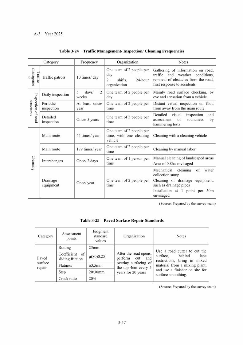
3-57
A-3 Year 2025
Table 3-24 Traffic Management/ Inspection/ Cleaning Frequencies
Category Frequency Organization Notes
Traffic m
anageme
nt Traffic patrols 10 times/ day
One team of 2 people per day 2 shifts, 24-hour organization
Gathering of information on road, traffic and weather conditions, removal of obstacles from the road, first response to accidents
Daily inspection 5 days/ 2 weeks
One team of 2 people per day
Mainly road surface checking, by eye and sensation from a vehicle
Periodic inspection
At least once/ year
One team of 2 people per time
Distant visual inspection on foot, from away from the main route
Inspection of road structures Detailed
inspection Once/ 5 years One team of 5 people per time
Detailed visual inspection and assessment of soundness by hammering tests
Main route 45 times/ year One team of 2 people per time, with one cleaning vehicle
Cleaning with a cleaning vehicle
Main route 179 times/ year One team of 2 people per time Cleaning by manual labor
Interchanges Once/ 2 days One team of 1 person per time
Manual cleaning of landscaped areasArea of 0.8ha envisaged
Cleaning
Drainage equipment Once/ year One team of 2 people per
time
Mechanical cleaning of water collection sump Cleaning of drainage equipment, such as drainage pipes Installation at 1 point per 50m envisaged
(Source: Prepared by the survey team)
Table 3-25 Paved Surface Repair Standards
Category Assessment points
Judgment standard values
Organization Notes
Rutting 25mm Coefficient of sliding friction μ(80)0.25
Flatness σ3.5mm Step 20/30mm
Paved surface repair
Crack ratio 20%
After the road opens, perform cut and overlay surfacing of the top 4cm every 5 years for 20 years
Use a road cutter to cut the surface, behind lane restrictions, bring in mixed material from a mixing plant, and use a finisher on site for surface smoothing.
(Source: Prepared by the survey team)

3-58
A-4 Year 2030
Table 3-26 Traffic Management/ Inspection/ Cleaning Frequencies
Category Frequency Organization Notes
Traffic m
anageme
nt Traffic patrols 11 times/ day
One team of 2 people per day 2 shifts, 24-hour organization
Gathering of information on road, traffic and weather conditions, removal of obstacles from the road, first response to accidents
Daily inspection 6 days/ 2 weeks
One team of 2 people per time
Mainly road surface checking, by eye and sensation from a vehicle
Periodic inspection
At least once/ year
One team of 5 people per time
Distant visual inspection on foot, from away from the main route
Inspection of road structures Detailed
inspection Once/ 5 years One team of 2 people per time, with one cleaning vehicle
Detailed visual inspection and assessment of soundness by hammering tests
Main route 45 times/ year One team of 2 people per time Cleaning with a cleaning vehicle
Main route 179 times/ year One team of 1 person per time Cleaning by manual labor
Interchanges Once/ 2 days One team of 2 people per time
Manual cleaning of landscaped areasArea of 0.8ha envisaged
Cleaning
Drainage equipment Once/ year
One team of 2 people per day 3 shifts, 24-hour organization
Mechanical cleaning of water collection sump Cleaning of drainage equipment, such as drainage pipes Installation at 1 point per 50m envisaged
(Source: Prepared by the survey team)
Table 3-27 Paved Surface Repair Standards
Category Assessment points
Judgment standard values
Organization Notes
Rutting 25mm Coefficient of sliding friction μ(80)0.25
Flatness σ3.5mm Step 20/30mm
Paved surface repair
Crack ratio 20%
After the road opens, perform cut and overlay surfacing of the top 4cm every 5 years for 20 years
Use a road cutter to cut the surface, behind lane restrictions, bring in mixed material from a mixing plant, and use a finisher on site for surface smoothing.
(Source: Prepared by the survey team)

3-59
2) Examination of the O&M implementation organization
A. O&M scope and implementing agency
O&M service such as that described below must be provided in order to supply safe road space that is
suitable for driving at high speed. An O&M subsidiary company will be established to implement the
O&M service, as described below, efficiently and rationally.
Table 3-28 O&M Scope
Category Content of O&M operations
Traffic management / traffic control
Collection of traffic information, traffic control, traffic patrols, accident response, detection and control of vehicles in breach of regulations, etc.
Toll collection Passage toll collection Periodic maintenance
Daily inspection, periodic inspection, cleaning, planting, traffic restriction, etc.
Repair Paved surface repair, bridge and structure repair Repair and improvement
Breakage and replacement of paved surface, functional improvement of bridges and structures, building up subsidence areas, etc.
Inspection and maintenance of devices
Inspection etc. of road facilities and buildings
(Source: Prepared by the survey team)
B. Operation & Maintenance Office
The above O&M subsidiary will have one Operation & Maintenance Office in the area of its
jurisdiction. A traffic control center able to monitor traffic flow on the expressway will be established
at the office, and the office will manage traffic patrols, daily maintenance, repair and inspection, and
toll collection. The following allocation of personnel at the Operation & Maintenance Office would be
appropriate on the basis of the above service level, if Japanese standards are applicable.

3-60
Table 3-29 Operation & Maintenance Office Staff Allocation
Section name
Executive staff Number of staff
Manager 1 Deputy manager 1
Section manager 1 General affairs section
Official in charge 1
Section manager 1 Tolls section Official in charge 1 Section manager 1 Traffic controller 15
Road traffic section
Traffic patroller 30 Section manager 1
Maintenance workers 25 Road
maintenance section Road inspectors 10
Section manager 1 Facilities maintenance
section Facilities inspectors 6
(Source: Prepared by the survey team)

3-61
C. Tollgate Tollgates will be built at the four interchanges within the jurisdiction area, An efficient 24-hour organization must be arranged for staff allocation at the tollgates. The following allocation of personnel at the Operation & Maintenance Office would be appropriate, if the Japanese standard was applied to the subject road section. All tollgates will use one-stop collection, in which toll collection and ticket issue are both performed by one person in one place.
Table 3-30 Personnel Allocation to Each Tollgate
IC installation positions
Entrance / Exit
No. of booths Necessary staff
Entrance 2NH3 intersection area Exit 4
36
Entrance 2Hanoi-Lao Cai Expressway intersection Exit 3
30
Entrance 3New NH23 Intersection area Exit 6
54
Entrance 5NH32 intersection area Exit 11
96
Total 36 216
24-hour system of two shifts per day.
(Source: Prepared by the survey team)
D. Vehicle Arrangement It is important that the Operation & Maintenance Office should own vehicles for various purposes,
such as inspection and patrolling, and have them always on hand, in order to maintain the expressway in good condition at all times. The following allocation of vehicles at the Operation & Maintenance Office would be appropriate, if Japanese standards are applicable for the section concerned.

3-62
Table 3-31 Operation & Maintenance Office Vehicle Arrangement
Type
Number of
vehicles
Specs Applications
Liaison vehicle 2
vehicles
Sedan General liaison duties related to expressway management
Road patrol cars 2
vehicles
Van
Inspection of road structures and discovery of damaged locations Supervision of maintenance and improvement work
Traffic management vehicles
3 vehicl
es Van
Traffic restriction at accident sites Emergency work to remove obstructions and accident victims
Maintenance working vehicles
2 vehicl
es Wagon-type Maintenance work
Road surface cleaning vehicles
1 vehicl
e Brushing truck in the 10t class Road surface cleaning
Water sprinkler vehicle
1 vehicl
e
Truck in the 10t class with a water sprinkling tank
Tree spraying, road surface cleaning
Jet cleaner 1
vehicle
10t truck with high-pressure cleaner
Cleaning of drainage facilities and joints
Self-propelled sign vehicle
3 vehicl
es
Truck in the 2t class with mounted sign
Traffic restriction Information delivery indicating congestion tailback end position
Beam lifter 1
vehicle
7t truck for elevated working at 13m
Cleaning of lighting equipment
(Source: Prepared by the survey team)

3-63
3) Maintenance Management Plan (road) Road maintenance management covers the road surface, artificial slopes, paving, drainage structures
and road structures (box culverts), etc. Maintenance management consists of inspections (daily, periodic and fault response inspections), cleaning, creation of road ledger and road management systems, repair judgments and selection of repair methods, and repair implementation.
A Inspections
Road inspection includes daily inspections, periodic inspections, and fault response inspections.
A-1 Daily inspections
Daily inspections are to identify abnormal conditions and damage on the road, and discover and remove obstacles on the road, in order to maintain road structures and ensure safe and smooth traffic flow. The frequency of daily inspections should be once in two days, as a general rule. The main inspection items are as stated in Table 3-31.
Table 3-32 Daily inspection items (roads)
Category Inspection content
Road surface condition Dirt and damage on the road surface Paving damage and wear Fallen stones or slipped earth on the road surface
Road shoulder condition Steps, holes and crumbling in the carriageways
Drainage facility condition Damage to drainage facilities and flow through them during rainfall
Artificial slope condition Crumbling or slippage of slopes, fallen stones, etc.
Artificial slope structure condition Cracks. movement and bulging in retaining walls and masonry walls
Condition of traffic safety facilities
Damage to guard rails, lighting facilities, road signs, etc. Obscuration of road signs by billboards etc. Unclear road markings Damage or other deformation in other associated facilities
Condition of median strip and planting facilities
Deformation of median strip and planting facilities
A-2 Cleaning
The purposes of cleaning include ensuring safety for road users and preventing disasters. Cleaning work covers road surfaces, drainage structures and other road-related facilities.
A-2-1. Road surface cleaning
Road surface cleaning is performed to remove accumulations of soil, small stones, fallen leaves and other materials near the road shoulder, and to facilitate the drainage of rainwater. It is performed twice a year, as required by roadside conditions.
A-2-2. Cleaning of drainage structures
The cleaning of drainage structures (drainage sumps and side gullies) is to remove accumulations of soil etc. that could impede the flow of water. Implement around twice a year, as a guideline

3-64
A-3 Periodic inspections Periodic inspections are detailed inspections of road paving, artificial slopes, retaining walls,
drainage facilities and box culverts, and other road structures.
Inspection involves a detailed visual inspection, and recording basic road data and inspection results
in the road ledger and inspection sheets. Where the condition of any part of the road has deformed, it
should be sketched or photographed to record the scale and progression of the change.
A -4 Inspection of abnormal conditions
In the event of an abnormal weather event or natural disaster, such as torrential rain or earthquake,
perform a suitable incident inspection to ascertain the damage to road facilities, whether the road is
passable, and other circumstances, and devise suitable response measures. If an error discovers a fault
requiring emergency response, suitable response measures must be implemented rapidly.
B Construction and management of the Road Management System (RMS)
The Road Management System (RMS) controls everything from road design through construction to
management, with an integrated system for all procedures. It is a system for making appropriate and
rational judgments on the procedures and methods for implementation of the most basic road-related
matters, which are design, construction, maintenance, inspection and improvement. It is intended to
assign priority rankings for actions such as maintenance and improvement, hold down expenses for
maintenance management as a whole, and implement various measures to maximize benefits. To that
end, it is necessary to apply a Life Cycle Cost (LCC) approach that considers and compares the entire
scope of initial construction costs and maintenance management costs.
Figure 3-24 Total Frame of RMS
Road InventoryDatabase
Inspection Database
Diagnosis Chart
StandardCountermeasure
Database
Registration intoRoad Inventory
Inspection
Registration ofInspection Results
Damage Evaluation
Soundness Evaluation
Deterioration Forecast
EngineeringDevelopment
forSoundness Evaluation &Deterioration Forecast
EngineeringDevelopment of
Inspection Method
Education for DamageEvaluation
EngineeringDevelopment forCountermeasure
Study of Time, Type &Cost of Countermeasure
Study of Priority
Preparation of RoadManagement &
Investment Plan
EngineeringDevelopment for Road
Management Plan
Road Database Road Management SystemEngineering Development
Personnel Training

3-65
Efficient implementation of the Road Management System requires inspection at the right time to
obtain road information, appropriate assessment of that information, and formulation of repair plans
suitable for the state of damage.
B-1. The main roles of inspection are to discover faults in the road and road structures and accurately
record the status of damage, and to obtain technical information for the planning of repairs and other
measures. To raise the accuracy of inspection results, it is important that the inspections should be
performed by a suitably-trained inspection engineer on the basis of an consistent inspection procedure,
and that the results be stored and accumulated in a database for effective use.
B-2. Damage assessments linked to the level of soundness of road structures must analyze inspection
results and make correct judgments of the cause and the state of deterioration. To that end, damage
history data should be accumulated and systematized to enable accurate judgment of the state of
deterioration.
B-3. Suitable repair plans must be formulated for the cause of the damage and the state of
deterioration, and to that end, a system must be built to accumulate and analyze repair history, store it in
a repair history database, and reflect it in repair plans.

3-66
4) Maintenance Management Plan (bridge)
Maintenance management for a bridge consists of inspections (daily, periodic and fault response
inspections), cleaning, creation of bridge ledger and bridge maintenance management systems, repair
judgments and selection of repair methods, and repair implementation.
A Inspections
A-1 Daily inspections
Daily inspections are to identify abnormal conditions and damage on the road, and discover and
remove obstacles on the road, in order to maintain road structures and ensure safe and smooth traffic flow.
For bridges in particular, daily inspections are to discover such faults and damage to the bridge that can be
observed from the road surface. For example, such inspections would cover car guardrails, bridge railings,
lighting and signage poles on the bridge, expansion joints, road surface condition, and towers and cables
(for a cable-stayed bridge). Faults in the deck slab can be detected from the condition of the road surface,
and faults in expansion joints and bearings can be detected from level steps and road noise. The frequency
of daily inspections should be once in two days, as a general rule, in the same way as daily inspections for
road maintenance management.
A-2 Cleaning
The purposes of cleaning include ensuring safety for road users and preventing disasters. Cleaning
consists of road surface cleaning and drainage structure cleaning.
A-2-1. Road surface cleaning
Road surface cleaning is performed to remove accumulations of soil, small stones, fallen leaves and
other materials near the road shoulder, and to facilitate the drainage of rainwater. It is performed twice a
year, as required by roadside conditions.
A-2-2. Cleaning of drainage structures
Cleaning of drainage structures (drainage sumps and pipes) is performed in order to prevent the
accumulation of soil etc. and the blockage of water flow. Implement around twice a year, as a guideline
A-3 Periodic inspections
Periodic inspections are intended to ascertain the state of the bridge and discover faults and damage at
an early stage, ensuring safe and smooth traffic movement, as well as gathering information for rational
maintenance management of the bridge. It is the most important type of inspection for maintenance
management.
To achieve these objectives, Periodic inspections are performed on the basis of an inspection procedure
which stipulates the inspection frequency and method, the elements to inspect, the items to inspect (types
of damage), damage judgment criteria, recording methods and other details.

3-67
The road manage takes responsibility and applies judgment to deciding the frequency of Periodic
inspections based on their content and purpose. For example, inspections that use inspection scaffolding
or bridge inspection vehicles etc to get as close as possible to the inspected elements and make a closeup
visual inspection should be performed every five years, as a general rule.
If a Periodic inspection discovers some kind of fault or damage in an element of the bridge, a repair is
made or a more detailed study performed, depending on the nature and severity of the problem.
A-4 Inspection of abnormal conditions
In the event of a major accident caused by an earthquake, or of a natural disaster or abnormal weather
event such as a typhoon or torrential rain, or an unexpected fault occurring in the bridge, this kind of
inspection is performed as necessary to confirm the safety of the bridge, ensure safe and secure traffic
flow, and prevent injury to the road or any third party.
If a fault is discovered that was not envisaged, the necessary investigation etc. is performed promptly
to identify the cause, and other bridges that might suffer from the same kind of problem are also inspected,
to ensure the safety of the bridges and prevent damage to third parties.
B Construction and Operation of the Bridge Management System (BMS)
The concept of bridge management is a relatively new one, but its basic approach is to assess public
investments in Japan on according to their cost-benefit (B/C etc.) and apply the scientific management
methods (QC, OR, IE, etc.) that were devised in the era of mass production.
In the apparatus industry era in which most of Japan’s bridges were built, initial construction cost was
the dominant consideration, and it appears that the costs that would become necessary through the
lifespan of the bridge (LCC) etc. were not always considered.
The approach of systematizing all procedures from the design of the bridge through to its construction
and management and controlling them in an integrated way (i.e. a Bridge Management System (BMS))
had an important role in changing the apparatus industrial bridge construction that went before into an
intellectual industry.
BMS is a system for making appropriate and rational judgments on the procedures and methods for
implementation of the most basic bridge-related matters, which are design, construction, maintenance,
repair, reinforcement, rebuilding and the like. It is intended to assign priority rankings for actions such as
maintenance, repair, reinforcement and rebuilding, hold down expenses for maintenance management as a
whole, and assess the implementation of various measures to maximize benefits.

3-68
Figure 3-25 The BMS Concept
Source: Survey Group “Road Bridge Management Manual”, August 2004, Japan Bridge Engineering Center
B-1 Deformation positions and deformation forecasting
To ensure the long-term durability of bridges, it is beneficial to forecast the future state of the Red
River Bridge 10, 20, 30, and 40 years in the future, with the emphasis on easy and reliable
implementation of maintenance management.
When forecasting, the anticipated risks for each position should be classified as “maintenance
management for positions where it is difficult to estimate the extent of damage” and “maintenance
management for positions where it is easy to estimate the extent of damage”, based on existing examples
of damage, the environmental conditions specific to the bridge, and its structural characteristics.
B-2 Main bridge structure
Deformation of the bridge structure should be forecast for each number of elapsed years and the points
subject to maintenance management should be defined.
Bridge ledger Construction data Inspection data Maintenance data Traffic surveys Accident investigations Cost data
Expenses
Bridge
Deterioratio
Financial constraint conditions (management information)
Potential countermeasures (Technical information)
Analysis by BMS
Needs
Future condition
Response options
Expenses

3-69
Table 3-33 Maintenance Management Points and Deformation Corresponding to Numbers of
Years (Bridge structure)
Years
elapsed
Target positions
10 years 20 years 30 years 40 years ~100 years
Steel deck plates Ponding Fatigue cracking
Secondary steel
girders
Deterioration of joint
sealant material
Deterioration of
anti-corrosion function
Water seepage into
girders, corrosion
Fatigue
cracking Steel
girders
Intersection area
Deterioration of joint
sealant material
Deterioration of
anti-corrosion function
Water seepage into
girders, corrosion
Fatigue
cracking
PC girder Cracking Salt damage, neutralization PC
girder Joints Corrosion and faults in anchoring points due to water leakage
Cables Deterioration of polyethylene pipes
girder side attachment Deterioration of sealant at pin joints Cables
Anchoring points on
the arch rib side Deterioration of cable covers
Bridge pier Cracking Salt damage, neutralization
Arch abutments Cracking Salt damage, neutralization
Bridge piers Cracking Salt damage, neutralization

3-70
B-3 Bridge accessories
Deformation of the appurtenant parts of the bridge should be forecast for each number of elapsed years
and the points subject to maintenance management should be defined.
Table 3-34 Maintenance Management Points and Deformation Corresponding to Numbers of
Years (Bridge appurtenant parts)
Years elapsed
Target positions 10 years 20 years 30 years 40 years
After 40
years
Paving Paving faults and irregular road surface
Bearings Functional impediments, subsidence, movement and tilting, blockage
with soil, bolt loosening
Expansion joints Expansion clearance fault, abnormal noise and vibration
Wheel guards Cracking, salt damage, neutralization
Bridge guard rails Loosening or corrosion of anchor bolts
Drainage
drainage sumps Reduced function due to blockage with soil
Drainage
equipment Steel drainage
channels
Reduced anti-corrosion function, corrosion, and reduced function due
to blockage with soil
B-4 Other appurtenant equipment
Deformation of the appurtenant equipment should be forecast for each number of elapsed years and the
points subject to maintenance management should be defined.
Table 3-35 Maintenance Management Points and Deformation Corresponding to Numbers of Years
(other appurtenant equipment)
Years elapsed
Target positions 10 years 20 years 30 years 40 years
After 40
years
Signage Corrosion of anchor bolts
Navigation channels lights Replacement of light bulbs and other consumables, deterioration of
electrical equipment

3-71
5)Yearly operation and maintenance cost of the RR4
There is so rare performance of the operation and maintenance (hereinafter referred to O & M) for
expressway in Vietnam so far. In order to analyze financial internal rate of return of this project, we have
to estimate yearly O & M cost of the the 37km section of the RR4. We have decided to estimate it in
comparison with Japanese and Vietnamese cost of O & M of expressway.
Table 3-36 Yearly Cost of O & M in Japanese Expressway Expressway
Company Yearly Cost (100 mil. Yen)
Length of Expressway (km)
Yearly Cost/Length of the Expressway(mil.Yen/km)
East NEXCO 1,723 3,575 48.2mil. Yen/km Central NEXCO 1,270 1,761 72.1mil. Ten/km West NEXCO 1,672 3,258 51.3mil. Yen/km Source: Web Site of the 3 NEXCO company
We have found out that an averaged yearly cost of O & M is 54.3 mil. Yen/km in Japanese expressway
according to Table 3-35. The cost of the 54.3 mil.Yen/km in Japanese expressway includes
countermeasure cost for preventing freezing of the road surface in winter season. But it does not need
such countermeasure cost in Hanoi, Vietnam. And Japanese level of O & M is considered to be so high
comparing to it’s in Vietnam. Besides in general O & M of the expressway needs much manpower, so it
needs to take into the difference of labor cost in Vietnam and Japan to estimate O & M cost in RR4,
Vietnam. Starting salary of the under graduated people in Vietnam is said to be 1/19 of that of the
Japanese.
Considering the above stated fact, yearly cost of O & M cost in RR4 has been estimated as follows.
54.3*0.8*1/10=4.34 mil. Yen/km
The estimated cost shown above considered to be a lot and safer side on the financial analysis for the
examination of RR4’s PPP scheme.
The total length of the project is 37-km, so yearly cost of O & M of the project has been estimated to
156.2 mil. Yen/ and 2 mil.USD in USD basis.
And Japan Center for International Finance Center has investigated price in the world and reported it in
Hanoi and Tokyo so far. According to the report in May. 2010, with Tokyo’s price index as 100, the
prices, in Hanoi bus and taxi fare starts prices, gasoline, rice, pork , orange, tomato, Big Mac , and liquid
crystal color TV are approximately 7, 68, 40, 14, 25, 6, 60 and 50 respectively. It seems to be no clear
relations among prices Hanoi and Tokyo, Japan. So it was impossible to estimate O& M cost of
expressway in Hanoi in reference to the report.
Next page shows a tabulated comparison between the leading long-span bridges in Japan.

3-72
For reference: Examination and comparison of inspection locations and items on existing bridges (1) Main bridge
Inspection types, frequencies, locations etc. are compared on the basis of inspection procedures for existing long-span cable-stayed bridges, and the a proposal for the inspection locations and methods, based on the characteristics of the main bridge section (compound cable-stayed bridge) is presented in Table 3- 37(a) and (b).
Note that this study has not considered inspection vehicle equipment, management elevators, road surface lighting, management lighting, pedestrian elevators, navigation channel lighting, aircraft hazard warning lights, lightning conductor equipment, snow melting and removal equipment, and
other equipment details. Also, the initial inspection is to be performed within one year from completion, and measurement positions other than for paint are the same as for precise inspections.
Table 3-37 (a) Comparison of inspection positions and methods for each inspection procedure on long-span bridges, and inspection position and method proposals for this bridge (main bridge section) (1/2)
Inspection
Procedures
Honshu-Shikoku Bridge Inspection management procedure
Tsurumi Tsubasa Bridge Inspection procedure proposal
Meikou Nishi Bridge Maintenance management manual
proposal
Ikara Ohashi bridge Bridge maintenance
management and inspection manual
proposal
This bridge (main bridge section) Inspection position and inspection method
proposal
Daily inspection Periodic
inspection Daily inspection Periodic inspection Daily
inspection Periodic inspection Daily inspection
Periodic inspection
Daily inspection Periodic
inspection Inspection
Type (Daily) (Patrol) (Basics) (Precision) (Daily) (summa
ry) (Detailed) (Daily) (Periodic [1]) (Periodic [2] (Daily) (Detaile
d) (Normal) (Distant visual)
(Close visual)
(Precision)
Inspection method
Inspection positions
Inspection
Frequency
4 days / week
Every 1~6
months
Every 1~2 years
1st, 3rd, 5th year
Every five years
thereafter
Daily Every half year
1st, 3rd, 5th year
Every five years
thereafter
Daily Annually
1st, 3rd, 5th year
Every few years
thereafter
Weekly Every 3 years
Once in 2 days
Every 5 years
Every 10 years
1st, 3rd, 5th and
10th years,
then every 10 years
Category Position Subcategory
Steel deck plates and floor system
Deck plates, longitudinal ribs, longitudinalgirders, lateral girders ○ ◎ ◎ ◎ ○ ◎
Concrete deck slabs ○ ◎ ○ ◎
Steel box girders Flanges, web plates, diaphragms ○ ◎ ◎ ◎ ○ ◎
Girder related
Concrete girders ○ ◎ ◎ ○ ◎
Tower columns ○ ◎ ◎ ◎ ○ ◎ ○ ◎
Horizontal members, lateral
beams ○ ◎ ◎ ◎ ○ ◎
Anchor bolts ◎ ○ ◎
Tower
Tower appurtenant parts ○ ◎ ◎ ◎ ○ ◎
Main cables
◎ ◎ ◎ ○ ◎ ○ ◎
See form measurem
ent column
Elastic restraint cables ◎ ◎ ◎ -
Cables
Cable vibration suppressor ○ ◎ ◎ ◎ ○ ◎ ◎ -
Cables girder side attachment ◎ ◎ ◎ ◎ ◎
Anchorage points Tower-side anchorage points ◎ ◎ ◎ ◎ ◎
Cables Cable sockets ◎ ◎ ◎ ◎
Cable related
Appurtenant parts Covers, bearing plates, etc. ◎ ◎ ◎ ◎
Bridge pier ○ ◎ ◎ ◎ ◎ ○ ◎
Foundation ◎ ◎ ◎ ◎ Substructur
e Substructure
appurtenant parts Inspection walkways, etc. ○ ◎ ◎ ○ ◎
Note 1) Symbols in the table indicate the content of inspection methods, as follows: ○: Visual inspection from a vehicle or from a distance, ◎: Close visual inspection (includes inspection by touch and hammering sound, non-destructive testing and other other simple measurements). ●: Measurement by instruments (measurements of form, stress, etc.)

3-73
Table 3-37 (b) Comparison of inspection positions and methods for each inspection procedure on long-span cable-stayed bridges, and inspection position and method proposals for this bridge (main bridge/ composite cable-stayed bridge) (2/2)
Procedures Honshu-Shikoku Bridge Inspection management procedure
Tsurumi Tsubasa Bridge Inspection procedure proposal
Meikou Nishi Bridge Maintenance management manual
proposal
Ikara Ohashi bridge Bridge maintenance
management and inspection manual
proposal
This bridge (main bridge section) Inspection position and inspection method
proposal
Daily inspection Periodic
inspection Daily inspection Periodic inspection Daily
inspection Periodic inspection Daily inspection
Periodic inspection
Daily inspection Periodic
inspection Inspection Type
(Daily) (Patrol) (Basics) (Precision) (Daily) (summary) (Detailed) (Daily) (Periodic
[1]) (Periodic [2]) (Daily) (Detailed) (Normal) (Distant
visual)(Close visual)
(Precision)
Inspection method
Inspection positions
Inspection Frequency
4 days / week
Every 1~6
months
Every 1~2 years
1st, 3rd, 5th year
Every five years
thereafter
Daily Every half year
1st, 3rd, 5th year
Every five years
thereafter
Daily Annually
1st, 3rd, 5th year
Every few years
thereafter
Weekly Every 3 years
Once in 2 days
Every 5 years
Every 10 years
1st, 3rd, 5th and
10th years, then every 10 years
Category Position Subcategory *1 *1 *1
Bearings
○ ◎ ◎ ◎ ◎ ○ ◎
See form measurem
ent column
Drainage equipment ○ ○ ◎ ○ ◎ ○ ◎ ○ ◎ ○ ○ ◎
Inspection walkways ○ ◎ ◎ ◎ ○ ◎
Objects carried by the bridge
○ ◎ ◎ ◎ ○ ◎
Wind-resistant stabilizer panels
○ ◎ ◎ ◎ ○ ◎
Anti-thrust works ○ ◎ ◎ ◎ ○ ◎
Working vehicle rails ○ ◎ ◎ ○ ◎
Pedestrian walkway ○ ◎ ○ ◎
Bridge Appurtenan
t parts
Bridge anticollapse structures
○ ◎
Expansion joints
○ ○ ◎ ○ ◎ ○ ◎ ○ ◎ ○ ○ ◎
See form measurem
ent column
Bridge railing and guard railing
○ ○ ◎ ○ ○ ◎ ○ ◎ ○ ○ ◎
Wheel guards ○ ○ ◎ ○ ◎ ○ ◎ ○ ○ ○ ◎
Paving ○ ○ ◎ ○ *2 ○ ◎ ○ ○ ◎
Signage-related ○ ○ ◎ ○ *2 ◎ ○ ○ ◎
Bridge surface works
Illumination-related ○ ○ ○ ○ ○ ○ ◎
Paint Paint Paint deformation (level or deterioration, amount of adhering salt)
◎ ◎ - *2 -
Temperature Air temperature and element surfaces - - - -
Main girders Vertical section line - - - -
Tower Deflection from vertical - - - -
Cable related Cable tension - - - - -
Substructure Amounts of translation, subsidence and rotation
- - - -
Girders and substructure Amount of relative displacement - -
Expansion joints and bearings Amount of displacement - - -
Form measureme
nt (Deformation measuremen
t)
Oil damper Oil quality and spring length - -
Note 1) Symbols in the table indicate the content of inspection methods, as follows: ○: Visual inspection from a vehicle or from a distance, ◎: Close visual inspection (includes inspection by touch and hammering sound, non-destructive testing and other simple measurements). ●: Measurement by instruments (measurements of form, stress, etc.)
Note 2) *1: Separate management standards are set for daily inspections (General items are covered, because inspection is visual from a vehicle) Note 3) *2: Separate management standards are set for the relevant items. Note 4) The measurement methods for form measurements (deformation measurements) are indicated in reference documents.

3-74
(2) Approach section (PC elevated section)
Inspection types, frequencies and locations etc. were compared based on the previous inspection procedure for general bridges, and the proposal for inspection locations and methods for the approach section (PC elevated section) was adapted for the characteristics of this bridge, as stated in Table 3-2-7.
Table 3-38 Comparison of inspection positions and methods for each inspection procedure on general (concrete) bridges, and inspection position and method proposals for this bridge (approach section/ PC elevated bridge)
Inspection Procedures
Ministry of Land, Infrastructure, Transport and
Tourism Bridge inspection procedure
proposal
Honshu-Shikoku Bridge Expressway Company Limited.
Inspection management procedure
Tokyo Bridge inspection procedure
Tokushima prefecture Bridge periodic inspection
manual proposal
This bridge (approach section/ PC elevated section)
Inspection position and inspection method proposal
Daily inspection
Periodic inspection
Daily inspection Periodic inspection Daily
inspectionPeriodic
inspection Daily
inspection Periodic
inspection Daily
inspection Periodic inspection Inspection Type (Normal) (Periodic) (Daily) (Periodic A) (Periodic B) (Patrol) (Periodic) (Normal) (Periodic) (Normal) (Distant visual) (Close visual)
Inspection method
Inspection positions
Inspection Frequency
Every 1 day~ 1 month
Every 5 years 4 days/ week Annually Every 1~5
years Every 3 months Every 5 years Annually Irregular Once in
2 days Every 5 years Every 10 years
Category Position Subcategory Note 2) Note 2)
Main girders ◎ ○ ○ ◎ ○ ◎ ◎ ○ ◎
Lateral girders ◎ ○ ○ ◎ ○ ◎ ◎ ○ ◎
Deck plates ◎ ○ ○ ◎ ○ ◎ ◎ ○ ◎
Superstructure
Outer cable ◎ (◎) (◎) (◎)
Bridge piers ◎ ○ ○ ◎ ○ ◎ ◎ ○ ◎
Bridge pier ◎ ○ ○ ◎ ○ ◎ ◎ ○ ◎ Substructure
Foundation ◎ ○ ○ ◎ ○ ◎ ◎ ○ ◎
Bearings Body, anchor bolts, mortar ◎ ○ ○ ◎ ◎ ◎ ○ ◎
Bridge anticollapse devices ◎ ○ ◎ ◎ ◎ ○ ◎
Drainage equipment ◎ ○ ○ ◎ ○ ◎ ◎ ○ ○ ◎
Inspection walkways ◎ ○ ○ ◎ ◎ ◎ ○ ◎
Appurtenant parts
Objects carried by the bridge ◎ ○ ○ ◎ ◎ ◎ ○ ◎
Expansion joints ◎ ○ ○ ◎ ○ ◎ ◎ ○ ○ ◎
Bridge railing and guard railing ◎ ○ ○ ◎ ○ ◎ ◎ ○ ○ ◎
Sound barriers ◎ ○ ○ ◎ ○ ◎ ◎ ○ ○ ◎
Wheel guards ◎ ○ ○ ◎ ○ ◎ ◎ ○ ○ ◎
Paving ◎ ○ ○ ◎ ○ ◎ ◎ ○ ○ ◎
Signage facilities ◎ ○ ○ ◎ ○ ◎ ◎ ○ ○ ◎
Bridge surface works
Illumination facilities ◎ ○ ○ ◎ ○ ◎ ◎ ○ ○ ◎
Note 1) Symbols in the table indicate the following inspection method types:
○: Visual inspection from a vehicle or from a distance, ◎: Close visual inspection (includes inspection by touch and hammering sound, non-destructive testing and other simple measurements)
Note 2) The procedures and manuals used by the Ministry of Land, Infrastructure, Transport and Tourism and Tokushima Prefecture cover periodic inspections, and they omit detailed descriptions of daily inspections, so the daily
inspection column is left blank.

3-75
(3) Inspection after a disaster
Inspection types, frequencies and locations etc. for use in the event of a disaster were compared based on the previous inspection procedure, and the proposal for inspection locations and methods was prepared for the characteristics of the main bridge, as stated in Table 3-2-7.
Table 3-39 Comparison of inspection types and locations in the previous inspection procedure for use in the event of a disaster, and proposal for inspection types and locations for this bridge in the event of a disaster
Inspection Procedures
Honshu-Shikoku Bridge Inspection management procedure
Tsurumi Tsubasa Bridge Inspection procedure proposal
Meikou Nishi Bridge Maintenance management manual proposal
Ikara Ohashi bridge Bridge maintenance
management and inspection manual
proposal
This bridge Proposal for inspection types and locations in the
event of a disaster
Inspection type Inspection to ascertain overall condition
Emergency restoration inspection
Primary disaster inspections
Secondary disaster inspections
Inspection of abnormal conditions [1]
Inspection of abnormal conditions [2]
Inspection of abnormal conditions
Inspection to ascertain overall condition
Emergency restoration inspection
Timing of implementation
When an earthquake occurs: Seismic intensity 4 or above When abnormal weather occurs: After implementation road passage restriction
After damage check by inspection to ascertain overall condition
When an earthquake occurs: Seismic intensity 4 or above When wind is very strong: 15m/s or more
When an earthquake occurs: Seismic intensity 5 or above When wind is very strong: 35m/s or more
When an earthquake occurs: Seismic intensity 5 or above
When an earthquake occurs: Seismic intensity 4 or above When wind is very strong: 20m/s or more
When an earthquake occurs: Seismic intensity 4 or above When wind is very strong: 30m/s or more
When an earthquake occurs: Seismic intensity 4 or above When abnormal weather occurs: After implementation road passage restriction(reference value: wind speed 20m/s or more)
After damage check by inspection to ascertain overall condition
Inspection type
Inspection location
Inspection method
Category Detailed category
As a general rule, inspection from a vehicle If damage is discovered, photograph or sketch it from the road and make a visual inspection from ground level.
Ground-level inspection (including simple measurements).
Visual inspection from a vehicle, visual inspection from a management walkway, closeup visual inspection from an inspection vehicle.
Make a more detailed instrument-based inspection if the primary inspection result indicates that one is necessary.
Ascertain overall condition and make an emergency restoration inspection.
Not as urgent as inspection [1], but make such inspections as are indicated as structurally necessary.
Inspect, visually from a vehicle, bridge deck or ground level, to find whether emergency restoration is required.
Make a visual inspection from a vehicle, to find whether emergency restoration is required.
Make a more detailed instrument-based inspection if the result of the inspection to ascertain overall condition indicates that one is necessary.
Road surface deformation
○ ○ ○ ○ Road surface
Obstructions on the road (lights, signs, etc.) ○ ○ ○ ○
Girder ○ ○ ○
Tower Base anchor bolts, etc.
○ ○ ○
Cables and anchorage points
○ ○ ○ ○
Cables Vibration dampers
○ ○ ○
Substructure
○ ○ ○
Bearing areas ○ ○ ○ ○
Bearings and
Expansion joints Expansion joints
○ ○ ○ ○
Elastic restraint cables
○ Vibration dampers Oil damper ○ ○
Bridge anticollapse system
Points recognized as damaged by the inspection to ascertain overall condition
Points recognized as damaged by the primary inspection
No inspection location stated
No inspection location stated
○
Points recognized as damaged by the inspection to ascertain overall condition

3-76
3.3 Outline of the Project
3.3.1 Basic Policy for Defining Project
(1) Road geometry conditions
1) Expressway sections (grade 100)
Vietnam’s design standards As stated in Table 3-40, according to TCVN 5729-97 Expressway Design
Requirement.
Table 3-40 Road Geometry Standards (expressway sections)
No. Item Unit Value
1 Road Grade Expressway
2 Design Speed km/h 100
3 No. of lanes lanes 6
4 Maximum superelevation % 7
5 Minimum radius for curve m 450
6 Maximum gradient % 5
2) Highway sections (Grade II for the delta)
Vietnam’s design standards As stated in Table 3-41, according to TCVN 4054-05 Highway Design
Requirement.
Table 3-41 Road geometric standards (highway sections)
No. Item Unit Value
1 Road Grade Grade II
2 Design Speed km/h 100
3 No. of lanes lanes 4
4 Maximum superelevation % 8
5 Minimum radius for curve m 400
6 Maximum gradient % 4
3) Urban roads
Vietnam’s design standards As stated in Table 3-42, according to TCVN 104-2007 Design Standard
for Urban Road.

3-77
Table 3-42 Road Geometry Standards (urban road)
Item Unit Value Item
1 Road Grade
2 Design Speed km/h 60
3 Maximum superelevation % 7
4 Minimum radius for curve m 125
5 Maximum gradient % 6

3-78
(2) Technical Criteria and Design Policy for Design of Bridge and Structures
1) Structure Design criteria
・Bridge Design Standard 22TCN272-05
・Load and Effect-Design Standard TVCN2737-1995
・Seismic – Resistant Structure Design TCXDVN 375-2006
・ Referring the bridge design standard AASHTO LRFD 2007
2) Principal Design Parameter
・HL93 Live Load(22TCN272-05)
・Ground Acceleration for Seismic Design : 0.11
・Structure Clearance for ordinary road(vertical) and expressway : 4.5m and 4.75m
・Structure clearance for navigation in waterways shall follow the grade of River Classification and
relevant regulations
The navigation route for Hong Ha bridge is classified into ClassⅠin the inland water ways
navigation rule, and structure clearance for Hong Ha bridge is prescribed to Width-80m*
Height-10m above water level by the regulation stated in the Table 3-43 shown below.
Table 3-43 Classification for the Inner Waterways Navigation (Unit:m)
Dimension for Navigation Dimension for Structures
River Canal Bridge Power
Line
Span Class
Depth Width Depth Width
Radius
of the
Curve River Canal
Height
fromWaterLevel
Height
fromWater
Level
Ⅰ 3.0- 90- 4.0- 50- 700- 80 50 10 12
Ⅱ 2.0-3.0 70-90 3.0-4.0 40-50 500-700 60 40 9 11
Ⅲ 1.5-2.0 50-70 2.5-3.0 30-40 300-500 50 30 7 9
Ⅳ 1.2-1.5 30-50 2.0-2.5 20-30 200-300 40 25 6* 8
Ⅴ 1.0-1.2 20-30 1.2-2.0 10-20 150-200 25 20 3.5 8
Ⅵ -1.0 10-20 -1.2 -10 60-150 15 10 2.5 8
Source:VITRANSS より
* Can be 5m under the agreement of the Law Review Office.
・Design Flood Probability P=1%

3-79
3) Design Policy
Structure Clearance for bridges in the RR4 should be designed considering planned high-water
probability 1% and 2% in the case of express way and highway GradeⅡrespectively.
Bridges in the RR4 are classified into 4 categories.
A Bridges crossing rivers
Bridges crossing river in the RR4 has been planned to be satisfied with design policy shown below:
・To be eternal structure with slim shape and in accordance with road condition and adjacent structure
・Corresponding to request of the urbanize, irrigation and environment development in the future
・Short duration of construction, easy building and be highly mechanized method
・Negligible small effect for inhabitants
・Guarantee function of structures and facilities under operating around site sound
・Make good use of ability and material and machineries for the regional contractors, the other side
applying rational transport technology
・Considering the architectural aesthetics
・Indicate the rational economical target
Adding stated above condition, each bridge types should be satisfied with typical request shown below:
・Mitigation damage by flood with 1% probability-no effect for bridge , guarantee safety of the dyke
and no harm to paddy field and civil engineering structures
・Bridge crossing river should follow clearance for navigation- At locations planned before for bridge
construction with no requirement for navigation clearance, if possible, box culvert can be constructed
instead for lower cost while maintaining drainage at the moment and for future. Target of box culvert
selection is to lower investment and lower the alignment profile.
B Hong Ha bridge
Hong Ha bridge should be designed to be satisfied with requests shown below:
・To be eternal structure with slim shape and in accordance with road condition and adjacent structure
・Corresponding to request of the urbanize, irrigation and environment development in the future
・To be satisfied with structure clearance for navigation
・No harm to the environment
・Practicable and highly mechanized construction method and no harm to the ship navigation and citizen
life

3-80
・Applying rational and cutting-edge advanced transport technology
・Having slim shape and highly aesthetics, improve the beautiful scenery more
・Structure should be selected considering the cost of project and maintenance in the future
C Viaducts
Viaducts in the RR4 should be satisfied with design policy shown below:
・To be eternal structure with slim shape and in accordance with road condition and adjacent structure
・Corresponding to request of the urbanization, irrigation and environment development in the future
・Certificate the clearance of the roads under the viaduct and relevant roads sufficient
・Short duration of construction, easy building and be highly mechanized method
・Guarantee function of structures and facilities under operating around site sound
・Make good use of ability and material and machineries in the regional contractors, the other side
applying rational transport technology
・Considering the architectural aesthetics
・Viaducts has length less than 10km , it is so surprising length that scope and economical criteria for
designing should be rationally and in detail considered.

3-81
3.3.2 Concept Design and the Use of Appropriate Equipment
(1) Road Planning
1) Road grade
The road grade for Ring Road 4 will be expressway to the south of National Route 18, and highway to
the north of it.
A Km118+730~Km135+400(-1+451) - North side of National Route 18
- Road type: Highway
- Road grade: Grade II for the delta, design speed 100km
- No. of lanes: Four lanes
B Km-1+451~Km 18+940 - South side of National Route 18
- Road type: Expressway
- Road grade: Grade 100, design speed 100km
- No. of lanes: Six lanes
2) Transverse sectional composition
A Expressway sections
A-1 Urban Zone, Populated Area
The transverse sectional composition for expressway within urban zones is as stated below, with a
right of way of 120m.
- Carriageway 6×3.75m=22.5m
- Central separator: 4.0+1.0×2=6.0m
- Shoulder: 3.75m×2=7.5m
- Reserve space: 20.0×2=40.0m
- Urban road: 12.0m×2=24.0m
- Sidewalk: 10.0m×2=20.0m
Right of Way: 120m
Figure 3-26 Road transverse sectional composition (expressway, urban zone)

3-82
A-2 Non-urban zone
The transverse sectional composition for expressway within urban zones is as stated below, with a
right of way width of 136m + slope width.
- Carriageway 6×3.75m=22.5m
- Central separator: 4.0+1.0×2=6.0m
- Shoulder: 3.75m×2=7.5m
- Reserve space: 50.0×2=100.0m
Right of Way: 136m+ slope width
Figure 3-27 Road Transverse Sectional Composition (Expressway, Non-urban Zone)
B Highway sections
B-1 General sections
The transverse sectional composition of general highway sections is as stated below, with a right of
way width of 62.5m + slope width.
- Carriageway 4×3.75m=15.0m
- Central separator: 0.5+0.5×2=1.5m
- Shoulder: 3.0m×2=6.0m
- Reserve space: 20.0×2=40.0m
Right of Way: 62.5m+ slope width
Figure 3-28 Road Width Configuration (highway, general section)

3-83
B-2 Residential areas The transverse sectional composition for highway within residential areas is as stated below, with a
right of way of 28.5~32.5m.
- Carriageway 4×3.75m=15.0m
- Central separator: 0.5+0.5×2=1.5m
- Shoulder: 3.0m×2=6.0m
- Sidewalk: 3.0~.5.0m×2=6.0~10.0m
Right of Way: 28.5m~32.5m
Figure 3-29 Transverse Sectional Composition (highway, residential zone)

3-84
(2) Bridge Planning
Road Standard for Ring Road 4(hereinafter referred to as RR4) is classified into 3 sections. According to
it’s function and traffic capacity, each section is designed to different scope and grade. Studied section for
Ring Road 4 is 37m in total length, the section is divided into 2 parts by road grade, northern section from
intersection NH18 is highway and southern section is expressway.
① Section 2: Km118+730~Km135+400(-1+451)・・・・・・・Northern section from intersection NH18 and
RR4
・Road Type : Highway
・Road Grade: Grade Ⅱ, Design Speed 100km/hr
・Number of Lane: 4 lanes
② Section 1 : Km-1+451~Km18+940・・・・・・・・・・Southern section from intersection NH18 and RR4
・Road Type : Expressway
・Road Grade: Grade 100, Design Speed 100km/hr
・Number of lane : 6 lanes
1) Cross Section for Bridge
Cross section of RR4 is expected to be a road with 6 lanes. Cross section of the bridge should be
principally in accordance with it’s road section. Cross section of viaducts, provincial road and National
Highway for Interchange structure should be in accordance with it’s road. Cross section of the viaducts
passing through industrial zone is as follows: To minimize the width of the land acquisition, a gap between
the up and down bridges should be removed.
Bridge cross section should be designed in accordance with it’s grade and applied criteria in each section
and to have sufficient number of traffic lane and required other facilities.
Cross section of the Hong Ha Bridge, the longest bridge with total length 5km in RR4, is designed
omitting inner road margin and emergency lane to minimize the total construction cost.

3-85
A Bridge cross section-Section 1
A-1 Main line bridge
Detailed cross sections of the main bridge in the main line are as follows:
6 Expressway Lanes : 6×3.75m = 22.50m2 Emergency Stop Lanes : 2×3.00m = 6.00m
2 Inner Road Margin : 2×1.00m = 2.00m4 Guard Rails : 4×0.50m = 2.00m1 Median Strip : 3.00m = 3.00m
Total Width = 35.50m
Figure 3-30 Cross section of bridge in main line
A-2 Urban road bridge arranged parallel with RR4
Two Urban road bridges has been planned to be constructed parallel both side of RR4 bridge with width
35.5m.
Outer edge of the urban road bridge has been planned to be 20m away from edge of the RR4 bridge.
Planned cross section of the urban road bridge is satisfied with requested life facilities around urban city
zone. The detailed cross sections are as follows:
2 Highway Lanes : 2×3.50m = 7.00m2 Mixed Traffic Lanes : 2×2.00m = 4.00m2 Guard Rails : 2×0.50m = 1.00m
Total Width = 12.00m
Figure 3-31 Bridge cross section for urban road bridge 13000
3x 3500=70002500500 2500 500
t im ®¦ ê n g g o m
2%2%
2 l µ n xe c ¬ g ií i Lµ n hç n h î pLµ n hç n h î p
16250
3x 3750=112503000 1000 1500
16250
35500
500 500 3x 3750=11250 300010001500 500500
2%
t im t uyÕn
3000
3 l µ n xe c a o t è c
2%
3 l µ n xe c a o t è c

3-86
A-3 Viaducts for main line
Except a distance between up and down bridges, cross section of the viaduct is similar to it’s of the
bridge for main line. The detailed cross section are as follows:
6 Expressway Lanes : 6×3.75m = 22.50m2 Emergency Stop Lanes : 2×3.00m = 6.00m2 Inner Margin Strip : 2×1.00m = 2.00m4 Guard Rails : 4×0.50m = 2.00m
Total Width = 32.50m
Figure 3-32 Cross section of the viaduct for main line
A-4 Fly over crossing the main line
Cross section of flyover crossing the main line is in accordance with law , grade and traffic capacity of
the crossing road.
A-5 Viaduct in an Interchange
Cross section and width of viaduct for main line and ramp shall follow the detailed design.
B Bridge cross section for section 2
Detailed bridge cross section for section 3 is as follows :
4 Highway Lanes : 4×3.75m = 15.00m2 Mixed Traffic Lanes : 2×2.50m = 5.00m1 Median Strip : 1×1.00m = 1.00m2 Inner Margin Strip : 2×0.50m = 1.00m4 Guard Rails : 2×0.50m = 1.00m
Total Width = 23.00m
3 l µ n xe c a o t è c
2%
3 l µ n xe c a o t è c
1000
16250
3x 3750=112503000 1000
16250
32500
500 500 3x 3750=11250 30001000 500500
2%
t im t uyÕn

3-87
Figure 3-33 Bridge cross section for section 2
11000
2x 3500=75002500 500500
2%
2 l µ n xe c ¬ g ií i
11000
23000
2x 3750=7500 2500500 500
2%
t im t uyÕn
2 l µ n xe c ¬ g ií i
1000
C Cross section for Hong Ha Bridge
Hong Ha bridge with total length 5km is the longest bridge in the RR4 . Construction cost for Hong Ha
bridge will effect seriously project cost for RR4 (North west section, total length 36km). So we have
studied the cross section in detail to provide same service level with Hong Ha bridge as road section.
However in order to cost down of the Hong Ha bridge’s we have omitted some elements in the original
section of the expressway. Namely minimization of the separate distance between up and down bridge,
emergency traffic lane(from 3.0m to 2.0m), inner road margin (from 1.0m to o.75m) and decrease of the
deign speed to 80km/hr on the bridge.
As a result of omission some elements, cross section of Hong Ha bridge is as follows:
Figure 3-34 Cross section for the Hong Ha bridge
15000
30000
3x 3750=11250 2000750 500
2%
t im t uyÕn
3 l µ n xe c a o t è c
15000
3x 3750=112502000500
2%
3 l µ n xe c a o t è c
7501000
6 Expressway Lanes : 6×3.75m = 22.50m2 Emergency Stop Lane : 2×2.00m = 4.00m1 Median Strip : 1×1.00m = 1.00m2 Inner Road Margin : 2×0.75m = 1.50m2 Guard Rails : 2×0.50m = 1.00m
Total Width = 30.00m

3-88
3.3.3 Project Cost (Construction cost of the Hong Ha Bridge and Approach Bridge)
(1) Option-1: PC Box Girder Bridge
Option-1:PC Box Girder Bridge Main Bridge USD329,277,251 3,409 USD/m2 96,600Approach Bridge USD 73,852,098 1,415 USD/m2 52,200All Bridge USD 403,129,349 2,709 USD/m2 148,800
GR1: PC Box Girder(in the river) (28 Spans)Item 1 Item 2 Item 3 Unit Quantity Unit Price(USD) Cost ( USD) Note
141,590,923Br. Girder Concrete m3 143,193 948.2 135,775,603Bridge Surface m2 96,600 60.2 5,815,320
36,670,347Concrete GR1 m3 81,165 451.8 36,670,347
30,460,560Cast-in-situ Pile GR1 φ2000 m 27,040 1,126.5 30,460,560
44,568,363Temporary Jetty 1 shallow m2 12,710 614.5 7,810,295Temporary Jetty 2 deep m2 44,719 819.3 36,638,277Temporary Road m2 7,630 15.7 119,791
75,987,058329,277,251253,290,19375,987,058
Total Cost/ Br. Surface Area : USD / m2 USD
GR2: PC Box Girder(crossing dikes) (6 Spans)Item 1 Item 2 Item 3 Unit Quantity Unit Price(USD) Cost (mil. USD) Note
16,803,70411,440,714
Br. Gider Concrete m3 6,522 1,671.1 10,898,914Br. Surface m2 9,000 60.2 541,800
1,626,133.0Concrete GR2 m3 6,079 267.5 1,626,133.0
3,689,760Cast-in-situ Pile GR2 φ1500 m 4,800 768.7 3,689,760
47,100Temporry Jetty 1 shallow m2 0 0 0Temporary Jetty2 deep m2 0 0 0Temporary Road m2 3,000 15.7 47,100
5,041,11121,844,81516,803,7045,041,111
Total Cost/ Br. Surface Area : USD / m2 USD
Overhead Charge
Direct Cost
Temporary Works
Overhead Charge Rate of Over head Charge : 30%
Cost
Contruction CostDirect Cost
2,427/m2
Direct Cost
Temporary Works
Overhead Charge Rate of Over head Charge : 30%
Cost
Totak CostDirect Cost
Direct Cost
Substructure
Foundation
Super Structure
Sub Structure
Foundation
Overhead Charge
3,409/m2
Direct Cost Super Structure

3-89
GR3: Super T type PC Br. (36 Spans)Itme 1 Item 2 Item 3 Unit Quantity Unit Price(USD) Cost (/USD) Note
40,005,60220,264,645
Br. Gider Condrete m3 22,522 784.3 17,664,005Br. Surface m2 43,200 60.2 2,600,640
5,630,291Concrete GR3 m3 20,407 275.9 5,630,291
12,668,176Cast-in-situ Pile GR3 φ1500 m 16,480 768.7 12,668,176
1,442,490Tepporary Jetty 1 shallow m2 800 614.5 491,600Temporary Jetty 2 deep m2 900 819.3 737,370Temporar Road m2 13,600 15.7 213,520
12,001,68152,007,28340,005,60212,001,681
Total Cost/ Br. Surface Area : USD / m2 USD Exchange Rate; 1USD=83yen , as of Dec. 2010
Overhead Charge Rate of Overhead Charge : 30%
Cost
Total CostDirect CostOverhead Charge
1204/m2
Foundation
Direct Cost
Temporary Works
Direct CostSuper Structure
下 部 工

3-90
(2) Option-2 : Cable-Stayed Bridge
Option- 2: Cable-Stayed Bridge Main Bridge USD 222,064,214 6,983 USD/m2 31,800Approach Bridge USD 272,607,092 2,329 USD/m2 117,030All Bridge USD 494,671,306 3,323 USD/m2 148,830
GR1: PC Box Girder (in the river) (19 Spans)Item 1 Item 2 Item 3 Unit Quantity Unit Price(USD) Cost (USD) Note
152,888,45495,022,980
Bridge Girder Concrete m3 96,100 948.2 91,122,020Bridge Surface m2 64,830 60.2 3,900,960
20,994,345Concrete GR1 m3 51,106 410.8 20,994,345
20,006,640Cast-in-situ Pile GR1 φ2000 m 17,760 1,126.5 20,006,640
16,864,489Temporary Jetty 1 shallow m2 10,170 614.5 6,249,465Temporary Jetty 2 deep m2 12,810 819.3 10,495,233Temporary Road m2 7,630 15.7 119,791
45,866,536198,754,990152,888,45445,866,536
Total Cost / Bridge Surface Area : USD/m2 USD 3,066/m2
GR2: PC Box Girder (crossing dike ) (6 Spans)Item 1 Item 2 Item 3 Unit Quantity Unit Price(USD) Cost (USD) Note
16,803,70711,440,714
Bridge Girder Concrete m3 6,522 1,671.1 10,898,914Bridge Surface m2 9,000 60.2 541,800
1,626,133Concrete GR2 m3 6,079 267.5 1,626,133
3,689,760Cast-in-situ Pile GR2 φ1500 m 4,800 768.7 3,689,760
47,100Temporary Jetty 1 shallow m2 0 0 0Temporary Jetty 2 deep m2 0 0 0Temporary Road m2 3,000 15.7 47,100
5,041,11221,844,81916,803,7075,041,112
Total Cost/ Bridge Surface Area :USD/m2
Direct Cost
Temporary Work
Overhead Charge Rate of Overhead Charge : 30%
Cost
Total CostDirect CostOverhead Charge
USD 2,427/m2
Super Structure
Sub Structure
Foundation
Direct Cost
Temporary Works
Direct Cost
Overhead Charge Rate of Overhead Charge : 30%
Cost
Total CostDirect CostOverhead Charge
Direct CostSuper Structure
Sub Structure
Foundation

3-91
GR3: Super T typed PC Bridge (36 Spans)Item 1 Item 2 Item 3 Unit Quantity Unit Price(USD) Cost (USD) Note
40,005,60220,264,645
Bridge Gieder Concrete m3 22,522 784.3 17,664,005Bridge Surface m2 43,200 60.2 2,600,640
5,630,291Concrete GR3 m3 20,407 275.9 5,630,291
12,668,176Cast-in-situ Pile GR3 φ1500 m 16,480 768.7 12,668,176
1,442,490Temporary Jetty 1 shallow m2 800 614.5 491,600Temporary Jetty 2 deep m2 900 819.3 737,370Temporary Road m2 13,600 15.7 213,520
12,001,68152,007,28340,005,60212,001,681
Total Cost/ Bridge Surface Area USD 1,205 /m2
GR4:Cable-Stayed Bridge(Steel) (1 Bridge : 4 Spans)Item 1 Item 2 Item 3 Unit Quantity Unit Price (USD) Cost (USD) Note
170,818,62699,880,069
Bridge Girder Steel Girder ton 10,090 4,826.5 48,699,385Floor Slab Concrete m2 35,722 494.0 17,646,668Pylon Concrete m3 13,929 1,478.3 20,591,241Diagonal Member Cable Strand ton 1,112 9,027.7 10,038,802 Number of Cable:11, Double Plane CableAccesaries LS 1 817,345.8 817,346 shoe and expansionBridge Surface Works m2 31,800 56.6 1,799,880Maintenance Facilities LS 1 286,746.9 286,747 400m2
5,836,180Concrete End Pier m3 5,838 331.3 1,934,129Concrete Intermediate Piers m3 11,778 331.3 3,902,051
52,828,311Steel Pipe Sheet Pile m 16,080 2,196.4 35,318,112Cast-in-situ Pile φ2000 m 1,760 1,126.5 1,982,640Bottom Slab Work m3 9,456 638.6 6,038,602Top Slab Works m3 14,859 638.6 9,488,957
12,274,066仮桟橋 浅い m2 0 0.0 0仮桟橋 深い m2 14,100 819.3 11,552,130仮設道路 m2 0 0.0 0タワークレーン・エレベーター L.S. 1 721,936.1 721,936
51,245,588222,064,214170,818,62651,245,588
Total Cost/ Brideg Surface Area USD 6,983/m2Exchange Rate; 1USD=83yen , as of Dec. 2010
Overhead Charge Rate of Overhead Charge : 30%Cost
Total Cost Direct CostOverhead Charge
Temporary Works
Overhead Charge Rate of Overhead Charge : 30%
Cost
Total Cost Direct CostOverhead Charge
Direct Cost Superstructure (including manufacturing and erection)
Substructure
Foundation
Direct Cost
Direct CostSuperstructure
Substructure
Foundation
Direct Cost
Temporary Works

3-92
(3) Option-3 Extradosed Bridge
Option-3: Extradosed Bridge Main Bridge USD 220,868,818 6,436 USD/m2 34,320Approach Bridge USD 273,767,904 2,309 USD/m2 118,590All Bridge USD 494,636,722 3,235 USD/m2 152,910
GR1: PCBox Girder(in the river) (19 Spans)Item 1 Item 2 Item 3 Unit Quantity Unit Price (USD) Cost (USD) Note
153,400,69795,479,918
Bridge Girder Concrete m3 96,500 948.2 91,501,300Bridge Surface m2 66,090 60.2 3,978,618
Consrete GR1 m3 51,106 410.8 20,994,345
Cast-in situ Pile GR1 φ2000 m 17,760 1,126.5 20,006,640
16,919,794Temporary Jetty 1 shallow m2 10,260 614.5 6,304,770Temporary Jetty 2 deep m2 12,810 819.3 10,495,233Temporary Road m2 7,630 15.7 119,791
46,020,209199,420,906153,400,69746,020,209
Total Cost/ Bridge Surface Area: USD/m2 3,017
GR2: PC Box Girder(crossing dike) (6 Spans)Item 1 Item 2 Item 3 Unit Quantity Unit Price (USD) Cost (USD) Note
17,184,39611,821,403
Bridge Girder Concrete m3 6,739 1,671.1 11,261,543Bridge Surface m2 9,300 60.2 559,860
1,626,133Concrete GR2 m3 6,079 267.5 1,626,133
3,689,760Cast-in-situ Pile GR2 φ1500 m 4,800 768.7 3,689,760
47,100Temporary Jetty 1 shallow m2 0 0 0Temporary Jetty 2 deep m2 0 0 0Temporary Road m2 3,000 15.7 47,100
5,155,31922,339,71517,184,3965,155,319
Total Cost/ Bridge Surface Area:USD/m2 2,402
Direct Cost
Temporary Works
Overhead Charge Rate of Overhead Charge : 30%
Cost
Total CostDirect CostOverhead Charge
USD/m2
Superstructure
Substructure
Foundation
Direct Cost
Temporary Works
Direct Cost
Overhead Charge Rate of Overhead Charge : 30%
Cost
Total Cost Direct Cost Overhead Charge
USD/m2
Direct CostSupersructure
Substructure
Foudation

3-93
GR3: Super T typed PC Bridge (36 Spans)Item 1 Item 2 Item 3 Unit Quantity Unit Price(USD) Cost (USD) Note
40,005,60220,264,645
Bridge Girder Concrete m3 22,522 784.3 17,664,005Bridge Surface m2 43,200 60.2 2,600,640
Concrete GR3 m3 20,407 275.9 5,630,291
Cast-in-situ Pile GR3 φ1500 m 16,480 768.7 12,668,176
1,442,490Temporary Jetty 1 shallow m2 800 614.5 491,600Temporary Jetty 2 deep m2 900 819.3 737,370Temporary Road m2 13,600 15.7 213,520
12,001,68152,007,28340,005,60212,001,681
Total Cost/ Bridge Surface Area:USD/m2 1,204
GR5: Extradosed Bridge (1 Bridge: 6 Spans)Item 1 Item 2 Item 3 Unit Quantity Unit Price(USD) Cost (USD) Note
169,899,09179,838,903
Bridge Girder Concrete m3 118,043 631.3 74,520,546Pylon Concrete m3 1,064 1,971.1 2,097,250Bridge Surface m2 34,320 85.5 2,934,360Maintenance Facilities LS 1 286,747.0 286,747 400m2
8,259,048Concrete End pier m3 5,838 316.9 1,850,062Concrete Intermediate Pier m3 20,224 316.9 6,408,986
66,404,721Steel Pipe Sheet Pile m 20,600 2,196.4 45,245,840Cast-in-situ Pile φ2000 m 1,760 1,126.5 1,982,640Bottom Slab m3 11,316 659.0 7,457,244Top Slab m3 17,783 659.0 11,718,997
15,396,419Temporary Jetty 1 shallow m2 1,000 614.5 614,500Temporary Jetty 2 deep m2 16,600 819.3 13,600,380Temporary Road m2 0 0.0 0Tower Crane, Elevator L.S. 1 1,181,539.0 1,181,539
50,969,727220,868,818169,899,09150,969,727
Total Cost/ Bridge Surface Area : 6,436 USD/m2Exchange Rate; 1USD=83yen , as of Dec. 2010
Overhead Charge Rate of Overhead Charge : 30%Cost
Total CostDirect CostOverhead Charge
Temporary Works
Overhead Charge Rate of Overhead Charge : 30%
Cost
Total CostDirect Costoverhead Charge
USD/m2
Direct CostSuperstructure
Substructure
Foundation
Direct Cost
Direct CostSuperstructure
Substructure
Foundation
Direct Cost
Temporary Works

4-1
Chapter 4 Evaluation of Environmental and
Social Aspects
In Vietnam, it is provided that environmental impacts shall be assessed in two stages of Initial
Environment Examination (IEE) and Environmental Impact Assessment (EIA). The assessment of the
project route is now in the intermediate phase of the first stage. This chapter reviews the environmental
and social impacts based on the IEE interim report, results of a current condition survey,
environment-related laws and regulations of Vietnam, etc.
4.1. Analysis of the current conditions from environmental and
social aspects
4.1.1. Analysis of the current conditions (1) Water quality
According to the IEE interim report, the pollution level of most of the surface stream water
located in the planned Ring Road No. 4 area is below the allowable value specified in the
Vietnamese technical standard QCVN08:2008 for surface stream water. However, the ammonium
ion (NH+) level exceeds the allowable value and the biochemical oxygen demand (BOD)
exceeded the allowable value at some measured points. In addition, groundwater contamination
was observed and (NH4+), iron (Fe) and Coliform at most of the measured points exceeded the
allowable value specified in the technical standard QCVN09:2008 for underground water.
Figure 4-1 BOD(mg/ 1) Figure 4-2 NH4(mg/ l)
(Source: “Country Synthesis Report on Urban Air Quality Management, ” ADB, 2006)
0.0
0.2
0.4
0.6
0.8
1.0
1996 1997 1998 1999 2000 2001
NH4
02468
10121416
1996 1997 1998 1999 2000 2001
BOD
Vietnam Standard 4mg/l Vietnam Standard
0.05mg/l

4-2
(2) Cultural relics
According to the IEE interim report, Soc Temple is located approximately 10 km southwest of
the project route in the Soc Son district. Thanh Nhan Temple and Thnah Nhan Pagoda in Thanh
Xuan Commune are also located in the district. They are 300 m away from the IC between the
project route and NH No. 4 but the IEE interim report suggests moving the alignment by around
1,000 m.
In addition to the above, a field survey confirmed a pagoda on the project route in Than Ha in
the district.
(3) Land use 1). Starting point 118+730~129+500
Most of the area is farmland where wet-rice double-cropping or double-cropping of wet-rice
and corn are practiced. According to local environmental consultants and local residents, the
cultivation periods of double-cropped rice are from December to April and from June to
September or October. Concerning double-cropping of rice and corn, rice is grown from February
to May and from June to September while corn is grown from September to January.
The expansion section of Provincial Highway No. 35 starts near KP126+750. There are
small-scale settlements along some sections of the highway. As described above, there is a
pagoda in Than Ha and there is also a small cemetery.
Photo 4-1 Paddy field near the starting point
Photo 4-2 Corn farm Photo 4-3 Settlement along Provincial Highway No. 35
Photo 4-4 Pagoda along Provincial Highway No. 35
Photo 4-5 Wetland along Provincial Highway No. 35
Photo 4-6 Cemetery along Provincial Highway No. 35

4-3
2). 129+500~130+000 (Highway Section)
3). 130+000~135+400 (Highway Section)
4). 135+400~0+0.0 (Intersection with National Highway No. 2, starting point of RR-4)
(Expressway Section)
Most of the area is farmland where double-cropping of wet-rice and corn is practiced. The
area is dotted with landowners’ houses. There are small-scale settlements in some sections but the
route goes around west of Provincial Highway No. 35 in the 130+000~131+500 sections,
avoiding the residential areas of the Phu Cuong settlement. The route departs from Provincial
Highway No. 35 near KP134.
5). 0+0.0~8+960 (Expressway Section)
There are farmhouses growing potatoes, tomatoes, turnips, etc. on the road alignment.
Photo 4-7 Turnip farm Photo 4-8 Irrigation canal
6). 8+960~13+900 (Expressway Section)
This section is comprised of the Red River bridge section and waterside land along the river.
There are many houses in the waterside land north of the Red River. The houses are “stilted” as a
measure against flooding. There are good roads and many papaya farm households. There are
also many houses in the southern waterside land.
Photo 4-9 Houses in the
waterside land Photo 4-10 Papaya farm in
the waterside land Photo 4-11 Pond separated
from the Red River

4-4
7). 13+900~18+940 (terminal point) (Expressway Section)
There are small-scale settlements chiefly engaged in banana farming.
Photo 4-12 Banana farm Photo 4-13 Banana farmhouses Photo 4-14 Near the terminal
point
(4) Air quality
According to the IEE interim report, the atmospheric pollution level in the vicinity of the
planned RR4 project area, excluding suspended dust particle (SDP), is below the allowable value
of the Vietnamese air quality standard “TCVN5937: 2005.”
Figure 4-3 CO(μg/m3) Figure 4-4 NO2(μg/m3) Figure 4-5 SO2(μg/m3)
(Source: “Vietnam Environment Monitor,” World Bank, 2003)
(5) Noise
According to the IEE interim report, the noise level in the residential areas in the vicinity of
the RR4 project area is below the allowable value of “TCVN5937: 2005” but exceeds the value
in some areas along the road.
(6) Ecosystem
The project route does not pass through any nature conservation parks. According to local
environmental consultants, the project route is unlikely to pass through any ecologically-sensitive
areas but a survey is required for the Red River and the wetland in KP126+750~129+500 because
rare aquatic organisms possibly inhabiting these areas.
0
50
100
150
200
250
2000 2001 2002 2003
MeanMax
0
5,000
10,000
15,000
20,000
25,000
30,000
2000 2001 2002 2003
MeanMax
050
100150200250300350400
2000 2001 2002 2003
MeanMax
Standard in Vietnam Standard in Vietnam Standard in Vietnam

4-5
4.1.2. Future forecast (without Project) There is a possibility of deterioration of air quality and increase in noise and vibrations due to
increased traffic jams in the central part of Hanoi city. There is also a possibility of worsening of
water pollution due to industrial water.
Concerning land use, farmland might be converted into industrial sites as a result of further
industrialization.

4-6
4.2. Environmental improvement effects associated with
implementation of the project
4.2.1. Natural and living environments
・ Possibility of reducing greenhouse gases by easing traffic jams
It is expected that concentrated traffic toward the central part of Hanoi will be eased by
promoting development on the northwestern side. This will ease traffic jams in the central part
of Hanoi and contribute to the global environment by reducing exhaust gases emitted from
vehicles (reduction of greenhouse gas emissions).
CO2 will be emitted during the road construction but it is expected to be offset after the road
is placed in service since traffic jams and annual CO2 emissions will be eased as noted above.
The following is method of analysis.
(1) Method of analysis
i) To calculate the future traffic volume and traveling speed of the traffic (both on “without” and
“with”)
ii) To calculate the future greenhouse gas emissions in the Traffic Network in Hanoi based on the
volume and traveling speed calculated in i).
Figure 4-6 Formula to calculate CO2 emissions by motor vehicles
Original unit of emission used for analysis is as shown in the Table 4-6 and 4-7. These tables. have
been introduced in “ Environmental Impact Assessment Guideline for CO2 emissions generated by
Road Project, Ministry of Environment, Japan. It shows that emission is decreasing as traveling speed
improves till 70km/h.
Annual total CO2 = emissions (t-CO2/年)
(Traffic volume by vehicle type x Road length x Original unit of emission by vehicle type) x 365
1,000,000
Total travel length

4-7
Table 4-1 Original unit of emission Figure 4-7 Original unit of emission and travel speed
(Source: Ministry of Environment, Japan)
As for “with the Project,” emission from construction work shall be also considered.
CO2 emissions generated by the construction materials and works will be obtained through Table
4-8.
Table 4-2 Emission from construction
(Source: “Proposal for estimation method for CO2 emissions generated by expressway project” An
Incorporated foundation “Expressway Technology Center”, Japan)
iii) To calculate the environment improvement effect in the Traffic Network in Hanoi achieved by the
Project by comparing each year the results calculated above
small vehicle large vehicle10 294.1 1345.420 206.0 1132.430 167.6 962.940 144.9 835.550 131.2 750.060 124.4 706.370 123.4 704.580 127.7 744.490 137.0 826.1
100 151.3 949.5110 170.3 1114.7120 194.1 1321.7
2020
(km/h)
average speed
Original unit of emission
0.0
500.0
1000.0
1500.0
10 20 30 40 50 60 70 80 90 100 110 120
average speed(km/h)
Orig
inal
uni
t of
emiss
ion(
gCO
2/km
)
small vehicle
large vehicle
(tC/km) (tCO2/km)
earthwork 1,338 4,906.0
steel birdge 14,362 52,660.7
PC bridge 6,948 25,476.0
tunnel 3,609 13,233.0
sectionCO2 original unit of emission

4-8
Figure 4-8 Flow for analyzing emission of CO2
To calculate the estimated emission of CO2
・ Possibility of ease of air pollution, noise, and vibration
Traffic volume will increase in the future in the area around the project as stated in Chapter 3.
Therefore, it can be considered that air pollution, the noise, and the vibration will be deteriorated.
Air pollution, the noise, and the vibration in the traffic network can be expected to be eased through
ease of traffic jam as the positive impact of the Project.
4.2.2. Social environment ・ Job creation through road and bridge construction
The road and bridge construction in the project will create temporary jobs. ・ Job creation and growth of the local economy by promoting development of the
northwestern side
The project is expected to promote development of the northwestern side of Hanoi city,
create jobs, and facilitate growth of the local economy through time reduction of traveling
among Hai Phong Port, Thai Nguyen, Bach Dang, Bac Nih, Hoa Lac Park. .
・ Smoother travel by easing traffic jams
As described in 4.2.1, it is expected that concentrated traffic toward the central part of
Hanoi will be reduced by promoting development on the northwestern side. This will ease
traffic jams in the central part of Hanoi and promote smoother travel.
To grasp the current traffic volume and traveling speed
To calculate future traffic volume and traveling speed taking account
of growing traffic volume rate in the traffic net work
To calculate CO2 emissions in the traffic network in Hanoi with calculated future traffic volume
and traveling speed
To calculate the emission of CO2 generated through
machinery and materials in the construction work
(ii)T
o ca
lcul
ate
the
estim
ated
em
issi
on
of C
O2
(iii)T
o ca
lcul
ate
the
effe
ct To calculate the environment improvement effect in the Traffic Network in Hanoi achieved by
the Project by comparing each year the results calculated above
(through traveling)
(through construction)
<without Project > <with Project>
(i) T
o ca
lcul
ate
the
futu
re tr
affic
vo
lum
e an
d tra
velin
g sp
eed
To calculate the future traffic volume and traveling speed taking
account in growing traffic rate and traffic
To calculate the emission of CO2 through traffic volume and
traveling speed in the traffic network in Hanoi

4-9
4.3. Impact of the project from environmental and social
aspects
4.3.1. Impact of construction and operation of the project on environmental and social aspects
(1) Permit and briefing session
(1) - 1 EIA and environmental permit
EIA is now in the intermediate phase of IEE, which is the first of the two stages. No
environmental permit has been obtained so far.
(1) - 2 Briefing session for residents
No briefing session for residents has been held so far. It is necessary to hold a briefing session
for local residents, receive opinions from them, and try to form a consensus.
(2) Anti-pollution measures
(2) - 1 Air quality
Air quality might worsen due to dust generated by the construction work, exhaust gases
emitted from construction vehicles, etc. However, the impact can be reduced by taking
appropriate measures. There is also a possibility of deterioration of air quality due to vehicle
traffic on the project route after the road is placed in service. However, it is expected that traffic
jams in the central part of Hanoi city will be eased and the air quality as a whole will be
improved by promoting development that is well-balanced with the central part of Hanoi city.
(2) - 2 Water quality
There is a possibility of temporary water pollution due to construction of bridge foundation in
the river. There is also a concern over water contamination caused by sewage from construction
workers’ accommodation. It is necessary to take appropriate measures against sewage from the
accommodation.
(2) -3 Noise and vibrations
Noise and vibrations might increase temporarily due to the construction work and passage of
construction vehicles. Appropriate measures such as prohibition or restriction of night construction
are required. It is expected that noise and vibrations will reduce in the traffic network as a whole
after the road is placed in service by easing traffic jams.

4-10
(3) Natural environment
(3) - 1 Conservation area
The project route does not pass through any conservation areas.
(3) - 2 Ecosystem
Most of the project route passes through farming areas, so it is believed that the project will
have little possibility to give significant impact to rare species. However, a detailed survey is
required for wetlands and river areas.
(3) - 3 Hydrology
There is a possibility of flooding, which may have a hydrological impact.
(3) - 4 Geography and geology
There is a possibility of geographical and geological impact such as land subsidence but the
impact can be minimized by proposing a soft ground countermeasure construction method.
(4) Living environment
(4) - 1 Relocation of residents
There are approximately 380 houses on the project route. As many as around 1,700 residents
will need to be relocated, assuming 4 or 5 persons per household, if the project is implemented.
Operational Policy of World Bank on resettlement stipulates 1) to minimize the number of
residents for resettlements, 2) to provide appropriate compensation, 3) to secure living standard
equivalent to or more than that before resettlement. JICA/ JBIC standard also stipulates to refer
to this Operational Policy.
Many houses concentrate in the section 2) 129+500-130+000, 3) 130+000-135+400, 6)
8+960-13+90. Houses in the section 2) 129+500~130+000 and 3) 130+000~135+400 are in the
village along existing road, many of which can be considered to be avoided by small change of
alignment. As for section 6) 8+960~13+900, about 90 houses concentrate in 2km. It is difficult to avoid houses
near Red River inside the bank, but stakeholder meeting shall be hold and appropriate compensation
must be provided. Also for other sections, it is necessary to discuss with local residents fully in
advance and make efforts to form a consensus.

4-11
Table 4-3 Houses on the proposed alignment
section length main features approximate
number
1) starting point 118+730~129+500 10.77km rice field, from 126+750
existing road
130
2) 129+500~130+000 (Highway Section) 0.5km rice field, existing road 25
3) 130+000~135+400 (Highway Section) 5.4km rice field, existing road 80
4) 135+400~0+0.0 (cross section with
NH2) (Expressway Section)
1.44km rice field 5
5) 0+0.0~8+960 (Expressway Section) 8.96km agricultural land 35
north side of Red River 60 6) 8+960~13+900 (Expressway Section) 4.94km
south side of red river 30
7) 13+900~18+940 (ending point)
(Expressway Section)
5.04km agricultural land
(banana)
15
total 37.05km 380
(4) - 2 Lives and livelihoods
There is a possibility that completion of the project route will promote the development of
secondary and tertiary industries and change the industrial structure. The project might affect the
lives of neighborhood residents substantially, so full prior discussion is required.
Ferry services are available on the Red River but they are not liner services connecting the
crossing points on the project route. Therefore, no large-scale unemployment is expected upon
completion of the project route.
(4) - 3 Cultural heritage
There is a pagoda on the road alignments. An appropriate measure including revision of
alignment is required.
(4) – 4 Landscape
There is no scenic spot around the project route, so it is believed that the project will not have
significant impacts. However, full discussion with local residents is required.
(4) –5 Minorities
No survey has been conducted so far, so a survey of residency needs to be conducted.

4-12
(4) –6 Labor environments
An appropriate labor environment and safety management is required for construction
workers.
(5) Others
(5) - 1 Impact during the construction
As described above, the project might affect air quality, water quality, noise and vibrations,
ecosystem, hydrology, geography and geology. However, it is believed that the impact can be
minimized by developing and implementing an appropriate construction plan and measures to
reduce the impact.
(5) - 2 Monitoring
A monitoring plan is required to ensure no unexpectedly large impact on the environment and
confirm appropriate implementation of the measures planned to reduce the environmental impact.

4-13
Table 4-4 Summary of the JICA/JBIC Checklist
Category
Environment-related
items
Current conditions, forecasts, etc. Impact
(1) EIA and environmental permit
・In EIA, the first stage report is now being prepared. - 1 Permit
and briefing session (2) Briefing session
for residents ・It is necessary to hold a briefing session for local residents, receive
opinions from them, and try to form a consensus. -
(1) Air quality ・Air quality might deteriorate during the construction. However, it is possible to reduce the impact by taking appropriate measures.
・It is expected that traffic jams in the central part of Hanoi city will be eased and the air quality will be improved as a whole after the road is placed in service by promoting development that is well-balanced with the central part of Hanoi city.
**
(2) Water quality ・ Currently, the values at some measured points exceed environmental standards.
*
2 Anti-pollution m
easures
(3) Noise and vibrations
・Noise and vibrations might increase during the construction. However, it is possible to reduce the impact by taking appropriate measures.
・It is expected that noise and vibrations will reduce in the traffic network as a whole after the road is placed in service by easing traffic jams.
**
(1) Conservation area ・The project route passes through no conservation areas. * (2) Ecosystem ・Currently, it is believed that the impact on the ecosystem will be
small. A detailed survey is required for wetlands and river areas. **
(3) Hydrology ・There is a possibility of flooding and hydrological impact. **
3 Natural
environment
(4) Geography and geology
・There is a possibility of geographical and geological impact such as land subsidence.
・The impact can be minimized by proposing a soft ground countermeasure construction method.
**
(1) Resettlement of residents
・ Large-scale relocation of residents involving around 400 households will take place. ***
(2) Lives and livelihoods
・There is a possibility of changing the industrial structure, so full discussion with residents living in the vicinity is required. **
(3) Cultural heritage ・There is a pagoda on the road alignment. An appropriate measure such as a revision of alignment is required. **
(4) Landscape ・It is believed that there will be no significant impact. * (5) Minorities and
indigenous people ・A survey is required. *
4 Social environment
(6) Labor environment
・Appropriate labor and safety management is required during the construction period.
**
(1) Impact during the construction
・There is a possibility of an impact on air quality, water quality, noise and vibrations, ecosystem, hydrology, geography and geology. However, the impact can be minimized by developing and implementing an appropriate construction plan and measures to reduce the impact.
***
5 Others
(2) Monitoring ・Measures based on an appropriate monitoring plan are required. -
Legend: -: No impact, not applicable; *: Minor impact; **: Moderate impact; ***: Significant impact

4-14
4.3.2. Comparison between the proposed project and other options with less environmental impact
As shown in the table below, the option with the least environmental impact from a short-term
perspective is “zero option” which means implementing no project. As described above, however,
the proposed project is expected to make a great contribution to easing traffic jams and the growth
of the local economy. It is believed that the project will be able to maximize positive effects on the
environment and society by taking appropriate measures to reduce negative impacts.
Table 4-5 Comparison of the environmental impact
Alternative 1 Zero option
Alternative 2 Ferry service between the
crossing points
Alternative 3 Proposed project
Advantages ・Least direct impact on the environment
・Less environmental impact at crossing points
・Respond to increased traffic volume in the future and promote well-balanced development of the entire Hanoi city
・Contribute to the growth of the local economy
Disadvantages ・ Can neither promote development of Hanoi city nor respond to further traffic jams
・Cannot respond to increased traffic volume in the future
・Does not contribute to easing traffic jams
・ Involves large-scale resettlement of residents
・ Involves environmental impacts including an impact on the crossing points
4.3.3. Discussions with the implementing agency and collecting information local experts
EIA is now in the intermediate phase of the first stage, which is an early stage of the
assessment. This time, therefore, no discussion was made with the implementing agency since it
was determined that the agenda was insufficient for discussion. However, a direct hearing was
conducted by consultants who are implementing EIA to complement information. Supposed
stakeholders are as follows:
・Ministry of Natural Resources and Environment
・Ministry of Transport
・Ministry of Planning and Investment
・Hanoi City People’s Committee
・District-level People’s Committee
・TEDI

4-15
・Environmental consultants
・Local residents

4-16
4.4. Overview of the environment- and society-friendly laws
and regulations in the partner country
4.4.1. Overview of environment- and society-friendly laws and regulations related to the implementation of the project
(1) Overview of environment-related laws and regulations
(1) - 1 EIA environment-related laws and regulations
1) Law on Environmental Protection: No. 52/2005/QH11
This law provides for implementation of EIA, including projects subject to EIA (Article 18),
matters to be included in reports (Article 20), and approval procedures (Article 21).
2) Decree No. 80/2006/ND-CP
This decree provides administrative instructions for the above Law on Environmental
Protection. It provides details of projects subject to EIA (Article 6 and Additional Clause 1),
requirements to serve as an EIA implementation consultant (Article 8), documents required for
EIA approval (Article 9), deadline of the review for approval (Article 12), situations that require
additional EIA (Article 13), etc.
3) Circular No. 08/ 2006/ TT-BTNMT
This circular provides administrative instructions for “1) Law on Environmental Protection”
and “2) Decree No. 80/2006” on the implementation of EIA. It also provides for the method of
implementing public consultation (Article 3-2).
4) Decree No. 21/2008/ND-CP
This decree complements and amends “2) Decree No. 80/2006.” It amends part of the details
of projects subject to EIA and obliges project implementers to discuss with the commune-level
Fatherland Front Committee (complement and amendment to Article 6a).
5) Circular No. 05/2008/TT-BTNMT
This is a replacement of “2) Circular No. 8/2006” on the implementation of EIA. It provides
administrative instructions for the above “1) Law on Environmental Protection,” “2) Decree No.
80/2006” and “4) Decree No. 21/2008.”
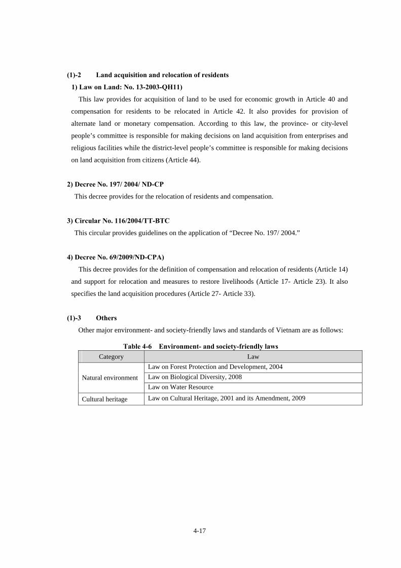
4-17
(1)-2 Land acquisition and relocation of residents
1) Law on Land: No. 13-2003-QH11)
This law provides for acquisition of land to be used for economic growth in Article 40 and
compensation for residents to be relocated in Article 42. It also provides for provision of
alternate land or monetary compensation. According to this law, the province- or city-level
people’s committee is responsible for making decisions on land acquisition from enterprises and
religious facilities while the district-level people’s committee is responsible for making decisions
on land acquisition from citizens (Article 44).
2) Decree No. 197/ 2004/ ND-CP
This decree provides for the relocation of residents and compensation.
3) Circular No. 116/2004/TT-BTC
This circular provides guidelines on the application of “Decree No. 197/ 2004.”
4) Decree No. 69/2009/ND-CPA)
This decree provides for the definition of compensation and relocation of residents (Article 14)
and support for relocation and measures to restore livelihoods (Article 17- Article 23). It also
specifies the land acquisition procedures (Article 27- Article 33).
(1)-3 Others
Other major environment- and society-friendly laws and standards of Vietnam are as follows:
Table 4-6 Environment- and society-friendly laws Category Law
Law on Forest Protection and Development, 2004 Law on Biological Diversity, 2008 Natural environment Law on Water Resource
Cultural heritage Law on Cultural Heritage, 2001 and its Amendment, 2009

4-18
Table 4-7 Environment-related standards Category No. Standards
TCVN5937-2005 Air quality standards Air quality
TCVN6438-2001 Vehicle exhaust gas standards
TCVN5942:1995:1995 Surface stream water quality standards
TCVN5944:1995 Underground water standards Water quality
TCVN6774:2000 Fresh water quality standards for aquatic organisms protection
TCVN6962:2001 Vibrations caused by construction and plants-Maximum allowable value in public and residential areas
Noise and vibrations
TCVN5949-1998 Noise standards
(2) Difference from the JICA/ JBIC guidelines
(2)-1 Public consultation
The JICA/JBIC guidelines mandate implementation of public consultation while Vietnamese
laws and regulations require it “as needed,” not making it mandatory.
(2)-2 Informal settler
The JICA/JBIC guidelines include informal settlers in compensation for relocation while,
basically, Vietnamese laws and regulations exclude informal settlers from compensation. However,
informal settlers may be eligible for compensation in Vietnamese laws and regulations depending on
their length of residence.

4-19
4.4.2. Details of EIA, etc. of the partner country required to implement the project An overview of EIA required in Vietnam is as follows:
Table 4-8 EIA overview
Overview Project ・ Important national projects
・ Projects that use part of the land of a natural reserve, national park, historical/cultural relic, natural heritage or registered sites of scenic beauty or have adverse effects on them
・ Projects that have might have adverse effects on a water resource, basin, coastal area or ecosystem protection area
・ Infrastructure construction projects in an economic zone, industrial complex, high-tech complex, export processing zone or home industry village
・ New construction projects in an urban district or concentrated residential district ・ Projects that involve large-scale development or use of underground water or natural
resources ・ Other projects that are likely to have adverse effects on the environment
【Law on Environmental Protection, Article 18-1】【Decree No. 80/2006/ND-CP】Timing ・ Simultaneously with a project feasibility study report
【Law on Environmental Protection Article 19- 2】・ Permission of investment, construction or development shall be approved and issued only
after the EIA report is approved 【Law on Environmental Protection, Article 22-4】
Description 1. Detailed explanation of the project 2. Assessment of conditions, vulnerability and capacity of the environment 3. Assessment of environmental impact, environment components to be affected and
social/economic components, and accident risks 4. Measures to reduce the impact, prevent environmental accidents, and countermeasures 5. Commitment to take measures for environmental conservation during construction and
operation of the project 6. Environmental management and audit plan 7. Environmental protection budget 8. Opinions and objections of representatives of communes and communities in the project
site 9. Provision of values and data of assessment
【Law on Environmental Protection, Article 20】Review and approval
① Projects decided or approved by the National Assembly, government or Prime Minister and projects that involve multiple industries or provinces
② Projects of which the approval authority belongs to central government ministries or agencies, excluding �
�Project-approving agency, environmental specialized agency of the province where the project site is located, experts, etc.
③ Projects of which the approval authority belongs to the province-level people’s committee
� Province-level people’s committee, province-level environmental specialized agency, environmental experts, etc.
【Law on Environmental Protection, Article 21- 1 to 21-3】Agency responsible for forming the approving agency and the
Agency responsible for forming the approving agency and the review committee for each of the three categories noted in the above “Review and approval.” Approval must be discussed and determined within 15 workdays from the date of receipt. ① Ministry of Natural Resources and Environment ② Central government ministries and agencies, each province-level people’s committee

4-20
review committee
【Law on Environmental Protection, Article 21-7】【Law on Environmental Protection, Article 22-1, 3】
Review deadline
① Projects of which the decision and approval authority belongs to the Prime Minister, government or National Assembly, and projects that involve multiple sectors or provinces: within 45 days from the date of document receipt
② Others: within 30 workdays from the date of document receipt 【Decree No. 80/2006/ND-CP, Article 12】
Additional EIA ・ When there is a change of the site, scale, design ability or technology of the project ・ When the project is not implemented within 24 months from the date of EIA report
approval 【Decree No. 80/2006/ND-CP, Article 13】
Rights of organizations, communities, individuals, etc.
Organizations, communities and individuals have the right to send a written request or petition to the reviewing agency. The reviewing agency is responsible for considering requests and petitions before making any conclusion or decision.
【Law on Environmental Protection, Article 21-6】
Publication, discussion, etc.
Measures for environmental conservation shall be publicized at the project site. 【Law on Environmental Protection, Article 23-1b】

4-21
4.5. What the Vietnam government should implement to realize the project
4.5.1. Completion of an EIA report
EIA shall be implemented in earlier stage, and the result shall be reflected to the Project
appropriately.
4.5.2. Discussion with local residents As described above, there are around 380 households on the road alignment. As many as 1,700
residents will be affected directly, assuming four or five persons per household. The project
involves widening of an existing road on part of the route, affecting settlements along the road.
This must be avoided if possible and, where this is impossible, appropriate measures including
compensation must be taken.
The project might alter the industrial structure. Therefore, the project might affect residents
living in the vicinity who are not living along the project route. It is necessary to discuss with local
residents fully and form a consensus to the extent possible.

4-22
【Supplement】JICA/ JBIC Checklist C
ateg
ory
Items related to the environment Major check points Yes: Y,
No: N* Specific arrangements/consideration for the environment and society
(Reasons and grounds for Yes/No, measures, etc.)
(1) EIA and environmental permit
(a) Have an environmental assessment report (EIA report), etc. been produced?
(b) Have the EIA report, etc. been approved by the government of the interested country?
(c) Does the approval of the EIA report, etc. have collateral conditions? Will the conditions be satisfied when there are collateral conditions?
(d) Has an environmental permit other than the above been obtained from the local supervisory authority, when required?
(a) N
(b) N
(c) -
(d) N
(a) The IEE report is being prepared.
(b) Unapproved
(c) Same as the above.
(d) The IEE report is being prepared but a permit has not been obtained yet.
(2) Briefing session for local stakeholders
(a) Has an appropriate briefing session been held for local stakeholders on the details and impact of the project, including information disclosure, and has their understanding been gained?
(b) Have comments of residents, etc. been reflected in the project?
(a) N
(b) N
(a) It is necessary to explain the details and impact of the project and receive opinions from interested municipalities and residents in an appropriate manner.
(b) It is necessary to reflect the comments in the project appropriately.
1 Pe
rmit
and
brie
fing
sess
ion
(3) Review of alternative proposals
(a) Have multiple alternative proposals of the project (including items related to the environment and society) been reviewed?
(a) SR (a) Further examination will be required.
(1) Air quality
(a) Will there be an impact by air pollutants emitted from traveling vehicles, etc? Will the impact meet the environmental standards, etc. of the interested country?
(b) Will the project further worsen the air pollution when the air pollution level near the route already exceeds the environmental standards? Will the project take measures for air quality?
(a) SR
(b) SR
(a) Air pollutants will be emitted from traveling vehicles but it is believed that they will have only minor adverse effects on the surrounding environment.
(b) The current air pollutant concentration mostly meets the Vietnamese environmental standards, excluding the SPM level. SPM exceeds the standards and might worsen further.
2
Anti-pollution m
easures (2) Water quality
(a) Will the downstream water quality be worsened by soil runoff from embankments, cut-earth portions, etc. where surface soil is exposed?
(b) Will the water flowing off the road surface contaminate water resources including underground water?
(c) Will the drainage from the parking and service areas, etc. meet the drainage
(a) Y
(b) Y
(c) SR
(a) Embankments and cut earth portions might cause muddy water during the construction.
(b) The water flowing off the road surface is unlikely to contaminate water resources badly. (Forecasting is required later in EIA.)
(c)There is a plan for a service area and the sewage of the service area

4-23
standards, etc. of the interested country? Will there be any water areas that do not meet the environmental standards of the interested country due to the drainage?
(d) Will the project affect water resources including wells in the vicinity?
might affect the water quality after the road is placed in service.
(d) Same as (b).
(3) Waste (a) Will the waste from the parking and service areas, etc. be handled/ disposed of appropriately based on the regulations of the interested country?
(a) SR (a)
(4) Noise and vibrations
(a) Will the noise and vibrations caused by traveling vehicles meet the standards, etc. of the interested country? (a) SR (a)
* Yes: Y, No: N, P: Possible, L: Less Unlikely, SR: Further Study Required

4-24
C
ateg
ory
Items related to the environment Major check points Yes: Y
No: N Specific arrangements/consideration for the environment and society
(Reasons and grounds for Yes/No, measures, etc.)
(1) Reserve (a) Is the project site located in a reserve designated by laws of the interested country, international treaties, etc? Will the project affect the reserve?
(a) N (a) There is no reserve along the project road.
(2) Ecosystem
(a) Is there any primeval forest, natural tropical forest, ecologically important habitat (coral reef, mangrove wetland, tidal flat, etc.) in the project site?
(b) Is there any habitat of precious species that need protection based on laws of the interested country, international treaties, etc. in the project site?
(c) Will any measures be taken to reduce expected serious impacts on the ecosystem?
(d) Will any measures be taken against blocking migration paths of wildlife and livestock, disjunction of habitats, traffic accidents involving animals, etc?
(e) Will the project road cause forest destruction, poaching, desertification, dry marsh, etc. associated with development? Is there any possibility of alien species (non-native species that did not inhabiting the area previously), diseases, pest, etc. moving in and disturbing the ecosystem? Are there any measures prepared against them?
(f) Will the natural environment be impaired substantially as a result of new area development when a road is constructed in an undeveloped area?
(a) L (b) L (c) - (d) SR (e) SR (f) L
(a) No important habitat, etc. has been confirmed along the project road.
(b) No habitat of precious species, etc. has been confirmed along the project road but this point needs to be confirmed regarding rivers and lakes.
(c) No serious impacts on the ecosystem by the project road have been forecasted.
(d) Appropriate measures including measures to prevent animal entrance are required.
(e) The project road will pass primarily through plains in farming areas, so no major impact is forecasted. However, the road will pass through wetlands and their neighboring forests and the impact on them needs to be reviewed. (f) Same as the above.
(3) Hydrology (a) Will geographic alternation or construction of a new structure have adverse effects on the flow of surface water and underground water?
(a) Review required
(a) Construction of embankments and a bridge might affect the surface stream water, so the design needs to consider flooding.
3 N
atur
al e
nviro
nmen
t
(4) Geography and geology
(a) Are there any geologically unsuitable points where soil falls or landslide might occur on the route? If so, will appropriate measures be taken in the construction method, etc?
(b) Are civil engineering works such as construction of embankments and
earth-cutting forecast to cause soil falls or landslide? Will appropriate measures be taken to prevent soil falls or landslide?
(c) Will soil run off from embankments, cut earth portions, soil yards or earth and sand pits? Will appropriate measures be taken to prevent soil runoff?
(a) SR (b) SR (c) SR
(a) The project road will pass through plains, so it is unlikely to have a major impact. However, the road will pass through soft ground areas and an appropriate construction method, etc. needs to be considered in the detailed design stage.
(b) There is a possibility of soil runoff from embankments and cut earth portions, so appropriate measures need to be considered in the detailed design stage to prevent soil runoff.
(c) Same as the above.
* Yes: Y, No: N, P: Possible, L: Less Unlikely, SR: Further Study Required

4-25
C
ateg
ory
Items related to the environment Major check points Yes: Y
No: N Specific arrangements/consideration for the environment and society
(Reasons and grounds for Yes/No, measures, etc.)
4 So
cial
env
ironm
ent
(1) Relocation of residents
(a) Will the implementation of the project cause involuntary relocation of residents? If so, will efforts be made to minimize the impact of relocation?
(b) Will an appropriate briefing session be held for residents to be relocated in
advance to explain compensation and measures to restore their livelihoods? (c) Will a study be conducted for relocation of residents and will a relocation plan
be developed including compensation at the reacquisition price and restoration of livelihoods after relocation?
(d) Will compensation money be paid before relocation? (e) Is there a written compensation policy? (f) Does the relocation plan pay appropriate attention to the socially vulnerable
among residents to be relocated, particularly to females, children, elderly people, poor people, minorities, indigenous people, etc?
(g) Will a consensus be formed with residents to be relocated before relocation? (h) Will a system be established for appropriate relocation of residents? Will
sufficient ability and budget be secured for relocation? (i) Are there plans for monitoring the impact of relocation? (j) Has a complaint handling mechanism been established?
(a) SR (b) SR (c) SR (d) N/A (e) Y (f) SR (g) N/A (h) SR (i) SR (j) SR
(a) Some sections of the project road will pass through residential areas, so the project will cause the need to relocate residents. Measures need to be considered to minimize the impact.
(b) An appropriate briefing session is required. (c) No study has been conducted so far and no relocation plan has
been developed yet. An appropriate study and relocation plan are required.
(d) Neither government ordinances nor circulars provide for the time of payment of compensation money. Payment before relocation needs to be discussed.
(e) A compensation policy needs to be developed based on government ordinances, circulars and JICA/JBIC guidelines.
(f) It is necessary to develop a plan, giving appropriate consideration to the socially vulnerable.
(g) It is necessary to secure time for full discussion and make efforts
to form a consensus. (h) The Hanoi City People’s Committee needs to take appropriate
measures for the relocation of residents. Support and confirmation by international consultants might be required.
(i) A monitoring plan needs to be developed. (j) A complaint handling mechanism needs to be established.
* Yes: Y, No: N, P: Possible, L: Less Unlikely, SR: Further Study Required

4-26
C
ateg
ory
Items related to the environment Major check points Yes: Y
No: N Specific arrangements/consideration for the environment and society
(Reasons and grounds for Yes/No, measures, etc.)
(2) Lives and livelihoods
(a) Will construction of a road or bridge as part of new development have an impact on existing means of transportation and the lives of residents engaged in the transportation? Will it lead to substantial alternation of land use and livelihoods, unemployment, etc? Does the project give consideration to reduce such impact?
(b) Will the project have adverse effects on the lives of other residents? Will the project make any arrangements to reduce the impact as needed?
(c) Is there any risk of diseases (including infectious diseases such as HIV)
caused by population inflow from other areas? Will appropriate public health arrangements be made as needed?
(d) Will the project have adverse effects on the road traffic in the surrounding areas?
(e) Will the project road disturb the travel of residents? (f) Will highway structures (overpass, etc.) disturb sunlight or radio reception?
(a) P (b) SR (c) SR (d) SR (e) P (f) L
(a) There is no regular ferry service in the bridge construction section, so the project will have almost no impact on the lives of people engaged in a ferry service. There will be alternations of land use and livelihoods, so full discussion with residents living in the vicinity is required.
(b) The project will not necessarily have adverse effects but it is a large-scale project and full discussion with residents living in the vicinity is required.
(c) Measures such as appropriate training are required.
(d) The project might cause traffic jams during construction, so
appropriate monitoring is required. (e) The road might split living areas, so full discussion with residents
is required. (f) The structures are unlikely to cause a problem but it is desirable to
review measures in the detailed design stage, as needed, to reduce the impact.
(3) Cultural heritage
(a) Will the project possibly harm archaeologically, historically, culturally and religiously valuable heritage, historic sites, etc? Will the project consider measures provided in domestic laws of the interested country?
(a) Y (a) A survey of current conditions of confirmed pagodas (religious buildings) and cemetery on the project route. It is necessary to discuss fully with residents living in the vicinity and take measures such as avoiding such sites to the extent possible.
(4) Landscape (a) Will the project have adverse effects on a landscape requiring special
considerations, if any? Will necessary measures be taken if there are adverse effects?
(a) SR (a) The project is unlikely to have adverse effects on the landscape but full discussion with residents living in the vicinity is required.
4 So
cial
env
ironm
ent
(5) Minorities and indigenous people
(a) Does the project give consideration to reduce the impact on the culture and way of life of minorities and indigenous people of the interested country?
(b) Will the rights of minorities and indigenous people for land and resources be respected?
(a) SR (b) SR
(a) Consideration needs to be made to reduce the impact on the culture and way of life of minorities and indigenous people of the interested country.
(b) Full consideration needs to be given for minorities and indigenous people.
* Yes: Y, No: N, P: Possible, L: Less Unlikely, SR: Further Study Required

4-27
C
ateg
ory
Items related to the environment Major check points Yes: Y
No: N Specific arrangements/consideration for the environment and society
(Reasons and grounds for Yes/No, measures, etc.)
4 So
cial
env
ironm
ent
(6) Labor environment
(a) Will the project observe the laws related to the labor environment of the interested country?
(b) Will the project take hardware safety measures for people involved in the project such as installation of safety equipment and control of harmful materials to prevent industrial accidents?
(c) Will the project plan and implement software measures such as development of a health and safety plan and provision of safety training for workers, etc. (including traffic safety and public health training programs) for people involved in the project?
(d) Will the project take appropriate measures so that security personnel involved in the project will not violate the security of the people involved in the project and local residents?
(a) SR (b) SR (c) SR (d) SR
(a) Monitoring is required during the construction. (b) Appropriate safety measures need to be taken in the detailed
design stage. (c) Appropriate safety training programs need to be developed in the
detailed design stage. (d) Appropriate training programs need to be developed in the
detailed design stage.
(1) Impact during the construction
(a) Will measures be taken to reduce contamination during the construction? (b) Will the construction have adverse effects on the natural environment
(ecosystem)? Will the project take measures to reduce the impact? (c) Will the construction have adverse effects on the social environment? Will the
project take measures to reduce the impact?
(a) SR (b) SR (c) SR
(a) Measures to reduce contamination need to be reviewed in EIA. (b) Measures to reduce the impact need to be reviewed in EIA. (c) Construction workers might cause problems with residents living
in the vicinity, so appropriate training programs need to be developed. Monitoring is also required.
5 O
ther
s
(2) Monitoring
(a) Of the above items related to the environment, will the project plan and implement a contractor monitoring program on items that will have an impact on the environment?
(b) How are the items, method, frequency, etc. of the project determined? (c) Will a contractor monitoring system be established? (d) Have the method, frequency, etc. of reporting from the contractor to the
supervisory authority, etc. been established?
(a) SR (b) SR (c) SR (d) SR
(a) An appropriate monitoring program is required. (b) Same as the above. (c) Same as the above. (d) Same as the above.
* Yes: Y, No: N, P: Possible, L: Less Unlikely, SR: Further Study Required


5-1
Chapter 5 Financial and Economic Evaluation 5.1 Project Cost
Project cost of road section with 4 lanes from Trung Gia to Phuc Yen is shown to Table 5-1, with
6 lanes from Phuc yen to Phung is shown to Table 5-2 and whole road section from Trung Gia to
Phung is shown to 5-3. Exchange Rate between us$ and Japanese Yen is 83 yen/us$ in Feb.2011.
Costs shown in the parenthesis are us$ basis in mil.
Based on the existing design quantity of 3 bridges option, the 3 bridges cost has been reviewed
with contracted Nhat Tan bridge’s price and other records in Japan as of Dec 2010.
Table 5-1 Project Cost from Trung Gia to PhucYen (4 Lanes, L=17km)
Items Cost(bil.Yen),(mil. us$) Note
Construction Cost(road) 6.9 ( 83.1) Including middle & Small sized Bridges and IC
Traffic Control Facilities 0.1 (1.2) Land Acquisition 1.9 ( 22.9) D/D & Consultant 0.8 ( 9.6) Contingency 1.9 ( 22.9) Total Cost 11.6 ( 139.8)
Table 5-2 Project Cost from Phuc Yen to Phung(6 Lanes, L=20km)
Items Cost(bil.Yen),(mil. us$) Note Road 11.5 (138.6) Including middle &
small sized Bridges and IC
PC Box Girder Bridge
33.5 ( 403.6) Option-1
Steel Cable-Stayed Bridge
41.0 (494.0) Option-2
HONG- HA Bridge Extradosed Bridge 41.0 (494.0) Option-3
Const. Cost
Total Const. Cost 45.0(542.1)~52.5(632.5)
Land Acquisition 8.2 (98.8)
D/D & Consultant(Including Traffic Control Facilities)
5.1 (61.4)
Contingency 10.4 (125.3) Const. Cost*20%
Total Cost 68.7(827.7)~76.2(918.1)

5-2
Table 5-3 Total Project Cost from Trung Gia to Phung(L=37km)
Items Cost(mi. us$) Note
Construction Cost 51.9(625.3)~59.4(715.7) Traffic Control Facilities 0.4 ( 4.8) Land Acquisition 10.1 (121.6) D/D & Consultant 5.9 (710.8) Contingency 12.3 ( 148.2) Total Cost 80.6 (971.1)~88.1(1,061.4)
Table 5-4 Project Cost in Vietnamese Dong and Japanese Yen Currency
in case of Cable-Stayed bridge (from Trung Gia to Phung, 37km)
Items Inner Currency
Dong:(Bil.VND)
Foreign Currency:Yen
(100mil.Yen)
Total Cost
in Japanese Yen
(100mil.Yen)
Note
Construction Cost
10,840.5 141 594 Cable –Stayed
Bridge
ETC Facilities 0 4 4
Land Acquisition Cost
2,417.0 0 101
Consultant Fee 478.6 39 59
Contingency 1,029.0 80 123
Total Cost 14,765.1 264 881
(Exchange Rate 100 mil.Yen=23.9304Bil.VND)
* Foreign Currency Ratio:264/881=30%

5-3
Table 5-5 Project Cost in Vietnamese Dong and Japanese Yen Currency
in case of PC Box Girder Bridge (from Trung Gia to Phung, 37km)
Item Inner Currency
Dong:(Bil.VND)
Foreign Currency :Yen
(100mil.Yen)
Total Cost
in Japanese Yen
(100mil.Yen)
Note
Construction Cost
11,175.9 52 519 PC Box Girder
Bridge
ETC Facilities 0 4 4
Land Acquisition Cost
2,417.0 0 101
Consultant Fee 478.6 39 59
Contingency 1,029.0 80 123
Total Cost 15,100.5 175 806
(Exchange Rate 100 mil.Yen=23.9304Bil.VND)
** Foreign Currency Ratio: 175/806=22%
In case of cable-stayed bridge Table 5-4, material and construction cost of diagonal cable and
steel girder have been appropriated as foreign currency (Japanese Yen), because they will be
imported from Japan or other foreign countries, besides two thirds of the overhead expenses has
been appropriated as foreign currency (Japanese Yen).
And then in case of the PC box girder bridge in Table 5-5, two thirds of the overhead expenses
has been appropriated as foreign currency (Japanese Yen) too.
With regard to consultant fee and contingency, two thirds of the total fee has been appropriated as
foreign currency.

5-4
5.2 Outline of the Result of Preliminary Financial and Economic Analysis
5.2.1 Calculation Basis for FIRR
When calculating Financial Internal Rate of Return (hereinafter referred to as FIRR) on
Investment for RR4(37km), calculation basis has been set taking consideration of indexes of
economical conditions in Vietnam as stated below. After Lehman-Shock, inflation index is not so
stable that inflation index has been set with averaged 5-year index except inflation index in the year
of 2008. Discount rate has been set with averaged nominal lending interest rate in past 5-year.
Substantial interest rate has been supposed to be 4.0% from the relation between discount rate and
inflation rate. An averaged balance between nominal lending interest rate and inflation rate from
2000 to 2007 is 2.8%. It varies strongly after 2008, so it will be difficult to examine it’s suitability.
But it is thought that the discount rate and inflation rate set below suitable in the main.
Discount Rate : 12.0%
Inflation Rate : 8.0%
Project Period: 30~40 years
Toll Price : 5 cent/km(900 VND/km), (Toll Price will be revised according to inflation rate every
year. )
Operation & maintenance cost : 50(Thousands USD/km/year)(refer to Page 3-68)
Dividend for SPC : None (Retined earnings assumed as profit)
Figure 5-1 Indexes of lending interest rate, inflation rate etc., in Vietnam
‐10.0
‐5.0
0.0
5.0
10.0
15.0
20.0
25.0
2000 2001 2002 2003 2004 2005 2006 2007 2008 2009
Lending interest rate (%) Deposit interest rate (%)
Inflation, GDP deflator (annual %) Real interest rate (%)

5-5
Table 5-6 Indexes of lending interest rate, inflation rate etc., in Vietnam 2000 2001 2002 2003 2004 2005 2006 2007 2008 2009
Lending interest rate (%) 10.6 9.4 9.1 9.5 9.7 11.0 11.2 11.2 15.8
Deposit interest rate (%) 3.7 5.3 6.4 6.6 6.2 7.1 7.6 7.5 12.7Inflation, GDP deflator (annual %) 3.4 1.9 3.9 6.7 8.2 8.2 7.3 8.2 21.7 5.6Real interest rate (%) 6.9 7.3 4.9 2.6 1.4 2.6 3.6 2.7 -4.9
Source: Data-Base of World Bank
Table 5-7 Forecast of Traffic Amounts and Toll Revenue Traffic (1000 vehicles/day) Toll Revenue Note
�NH3-NH2 �NH2-NH32 (mil. USD/year)
2015 15.9 22.5 17.9 Supposed to be opened in 2015
2020 25.1 33.1 37.9
2025 34.1 45.6 72.9
2030 45.1 60.9 136.0
5.2.2 Case setting to be analyzed in PPP scheme for implementing construction project
Six cases of PPP scheme FIRR analysis has been proposed and conducted in order to be
considered which is the best implementation scheme for investment of private company and
government.
Figure 5-2 Studied Section
(2) Phuc Yen – Phung (19km) (1) Trung Gia – Phuc Yen(17km)
Hong Ha bridge Phung Phuc Yen
Trung Gia
Noi Bai Airport
NH-32
NH-18
NH-3

5-6
Table 5-8 Supposed 6 cases in PPP scheme for implementation of the project “ RR4 (37km)” Road Length
Project Cost
Investors for the Project
Form of Investment
Case-0
37km
971 mil.USD
Gov.’s VGF: 0 % Private Investors :100 %(Const.、D/D、S/V、O&M)Debt/Equity Ratio= 7 : 3
・Capital Investment ・Borrowing from commercial
banks
Case-1
37km
971 mil.USD
Gov.’s VGF: 30% Private Investors :70 %(Const.、D/D、S/V、O&M)
D/E Ratio= 7 : 3
・Capital Investment ・Borrowing from commercial
banks
Case-2
37km
971 mil.USD
Gov.’s VGF: 30% Private Investors :70 %(Cont.、D/D、S/V、O&M)D/E Ratio= 7 : 3
・Capital Investment ・Borrowing from Public fund such as JICA,W.B.,and ADB 2 STEP Loan
Case-3
37km
971 mil.USD
Gov.’s VGF: 50% Private Investors : 50%(Const.、D/D、S/V、O&M)D/E Ratio= 9 : 1
・Capital Investment ・Borrowing from Public fund such as JICA,W.B.,and ADB
2 STEP Loan
Case-4
20km (Phuc Yen~ Phung ) 828 mil.USD
Note 1
Gov.’s VGF: 30% Private Investors : 70%(Const.、D/D、S/V、O&M)D/E Ratio= 7 : 3
・Capital Investment ・Borrowing from Public fund such as JICA,W.B.,and ADB
2 STEP Loan
Case-5
Construction 32km
425 mil.USD O & M
37km Note 2
Gov. will construct Hong Bridge with JICA’s Yen Loan.
Private Investors will be responsible for O & M of whole section of 37km and construction of the road section 32km except Hong Ha Bridge.
・JICA’s Yen Loan ・Capital Investment ・Borrowing from commercial banks
Note 1. Design and construction of the section from Trung Gia to Phuc Yen, 17km will be
separately implemented by other PPP contractor. And PPP contractor of this project will implement
design, construction of the section from Phuc Yen to Phung,20km, besides operation and
maintenance of whole section from Trung Gia to Phung, 37km integratedly.
Note 2. Design and construction of the Hong Ha bridge with length 5km will be implemented by
the government utilizing ODA loan separately. And PPP contractor of the project will implement
design and construction of the section from Trung Gia to Phung except Hong Ha bridge with length
32km, besides operation and maintenance of the whole section from Trung to Phung including
Hong Ha bridge with length 37km.

5-7
5.2.3 Result of preliminary financial analysis
(1) FIRR in Case-0
・In case of borrowing project fund from commercial banks, FIRR resulted in 3.2% (‹ 12%)and
shown it in poor financially.
・Construction cost of Hong Ha Bridge is so expensive that it has given a great impact to viability
of the project.
・Interest burden is heavy especially within 10 years after operation, which is higher than toll
income. It will also have cash-flow problem since deficit on single year will continue till 18 years
after operation.
FIRR: 3.2 %
NPV: -617.4(mil USD)
Turned into profit in single year : 2033(after 18 years operation )
Turned into profit (accumulated): 2044(after 28years operation)
Financing Scheme
Terms of repayment
Interest Rate:12.0 %
Period:35 years
Method of payment:equal principle method
Construction S/V D/D O&M
Private Investors:100%
Loan from commercial bank: 70% Equity
Toll
income
subordinate
Interest Rate 12..0 %

5-8
Table 5-9 FIRR , Cash Flow in Case-0
Year Investment Return MaintenancePaid Interest Tax Repayment Cash Flow 1 -293.1 0.0 0.0 0.0 0.0 0.0 -293.12 0.0 0.0 0.0 0.0 0.0 0.0 0.03 0.0 0.0 0.0 0.0 0.0 0.0 0.04 0.0 0.0 0.0 -20.5 0.0 0.0 -20.55 0.0 0.0 0.0 -26.2 0.0 0.0 -26.26 0.0 27.6 -1.8 -96.4 0.0 -1.6 -72.17 0.0 32.6 -1.9 -105.3 0.0 -1.8 -76.48 0.0 38.2 -2.0 -114.8 0.0 -2.0 -80.79 0.0 44.4 -2.2 -124.6 0.0 -2.2 -84.6
10 0.0 51.5 -2.4 -135.0 0.0 -2.5 -88.411 0.0 59.7 -2.6 -145.7 0.0 -2.8 -91.312 0.0 69.0 -2.8 -156.6 0.0 -3.1 -93.513 0.0 79.3 -3.0 -167.5 0.0 -3.5 -94.714 0.0 90.9 -3.2 -178.5 0.0 -3.9 -94.815 0.0 103.8 -3.5 -189.3 0.0 -4.4 -93.416 0.0 119.5 -3.8 -199.3 0.0 -4.9 -88.617 0.0 137.0 -4.1 -208.5 0.0 -5.5 -81.118 0.0 156.6 -4.4 -216.2 0.0 -6.2 -70.219 0.0 178.4 -4.8 -222.2 0.0 -6.9 -55.420 0.0 202.8 -5.1 -225.7 0.0 -7.7 -35.821 0.0 219.0 -5.6 -227.4 0.0 -8.7 -22.622 0.0 236.5 -6.0 -227.2 0.0 -9.7 -6.423 0.0 255.4 -6.5 -226.0 0.0 -22.9 0.124 0.0 275.9 -7.0 -223.3 -4.4 -41.2 -0.025 0.0 297.9 -7.6 -218.3 -11.0 -61.6 -0.626 0.0 321.8 -8.2 -210.9 -18.7 -83.3 0.727 0.0 347.5 -8.8 -200.9 -27.5 -111.1 -0.828 0.0 375.3 -9.5 -187.6 -37.6 -140.2 0.429 0.0 405.3 -10.3 -170.8 -49.1 -175.5 -0.330 0.0 437.8 -11.1 -149.7 -62.3 -214.0 0.631 0.0 472.8 -12.0 -124.0 -77.2 -259.9 -0.432 0.0 510.6 -13.0 -92.8 -94.2 -310.2 0.433 0.0 551.5 -14.0 -55.6 -113.5 -81.8 286.634 0.0 595.6 -15.1 -45.8 -126.7 -37.8 370.135 0.0 643.2 -16.3 -41.3 -139.4 -42.4 403.836 0.0 694.7 -17.6 -36.2 -153.2 -47.5 440.237 0.0 750.3 -19.0 -30.5 -168.2 -53.2 479.438 0.0 810.3 -20.6 -24.1 -184.4 -59.5 521.639 0.0 875.1 -22.2 -17.0 -202.0 -66.7 567.240 0.0 945.1 -24.0 -9.0 -221.1 -74.7 616.4
IRR 3.2%NPV -617.4

5-9
(2) FIRR in Case-1
・Though Government has funded 30% of project cost as Viability Gap Funding, in case of
borrowing project fund from commercial banks, FIRR resulted in 9.4 %(<12.0%)and show it in
poor financially.
・Construction cost of Hong Ha Bridge is so expensive that it has given a great impact to viability
of the project.
・Interest burden is heavy especially within 10 years after operation, which is higher than toll
income. It will also have cash-flow problem since deficit on single year will continue 11 years after
operation.
FIRR : 9.4%
NPV : -160.(mil USD)
Turned into profit in single year : 2027(12 years after operation)
Turned into profit (accumulated) : 2034(19 years after operation)
Sensibility Analysis for Fluctuation of Traffic Amounts
Traffic Amounts
-20% -10% 0% +10% +20%
FIRR 7.4% 8.5% 9.4% 10.3% 11.2
NPV(mil USD) -265.2 -212.4 -160.0 -108.1 -56.4
Financing Scheme
Terms of repayment
Interest Rate:12.0 %
Period:35 years
Method of payment:equal principle method
Construction S/V D/D O&M
Gov. Fund (VGF):30% Private Investors:70%
Bank loan: 70% Equity
Toll
income
subordinate
Interest rate 12..0 %

5-10
Table 5-10 Table 12 FIRR,Cash Flow in Case-1
Year Investment Return MaintenancePaid Interest Tax Repayment Cash Flow 1 -205.2 0.0 0.0 0.0 0.0 0.0 -205.22 0.0 0.0 0.0 0.0 0.0 0.0 0.03 0.0 0.0 0.0 0.0 0.0 0.0 0.04 0.0 0.0 0.0 -14.4 0.0 0.0 -14.45 0.0 0.0 0.0 -18.3 0.0 0.0 -18.36 0.0 27.6 -1.8 -66.5 0.0 -1.1 -41.77 0.0 32.6 -1.9 -71.5 0.0 -1.2 -42.08 0.0 38.2 -2.0 -76.5 0.0 -1.4 -41.89 0.0 44.4 -2.2 -81.4 0.0 -1.6 -40.7
10 0.0 51.5 -2.4 -86.0 0.0 -1.7 -38.611 0.0 59.7 -2.6 -90.2 0.0 -2.0 -35.012 0.0 69.0 -2.8 -93.8 0.0 -2.2 -29.813 0.0 79.3 -3.0 -96.5 0.0 -2.5 -22.714 0.0 90.9 -3.2 -98.2 0.0 -2.7 -13.315 0.0 103.8 -3.5 -98.4 0.0 -3.1 -1.316 0.0 119.5 -3.8 -98.1 0.0 -14.4 3.217 0.0 137.0 -4.1 -96.3 -4.3 -28.9 3.518 0.0 156.6 -4.4 -92.9 -9.9 -45.3 4.019 0.0 178.4 -4.8 -87.4 -16.7 -65.8 3.720 0.0 202.8 -5.1 -79.5 -24.6 -88.4 5.021 0.0 219.0 -5.6 -68.9 -31.2 -109.1 4.222 0.0 236.5 -6.0 -55.8 -38.8 -40.8 95.123 0.0 255.4 -6.5 -50.9 -44.6 -7.6 145.824 0.0 275.9 -7.0 -50.0 -49.8 -8.5 160.525 0.0 297.9 -7.6 -49.0 -55.5 -9.6 176.426 0.0 321.8 -8.2 -47.9 -61.6 -10.7 193.527 0.0 347.5 -8.8 -46.6 -68.1 -12.0 212.028 0.0 375.3 -9.5 -45.1 -75.3 -13.4 232.029 0.0 405.3 -10.3 -43.5 -83.0 -15.0 253.530 0.0 437.8 -11.1 -41.7 -91.3 -16.8 276.831 0.0 472.8 -12.0 -39.7 -100.4 -18.9 301.832 0.0 510.6 -13.0 -37.4 -110.2 -21.1 328.933 0.0 551.5 -14.0 -34.9 -120.8 -23.7 358.234 0.0 595.6 -15.1 -32.1 -132.2 -26.5 389.735 0.0 643.2 -16.3 -28.9 -144.6 -29.7 423.736 0.0 694.7 -17.6 -25.3 -158.0 -33.2 460.537 0.0 750.3 -19.0 -21.3 -172.6 -37.2 500.138 0.0 810.3 -20.6 -16.9 -188.3 -41.7 542.839 0.0 875.1 -22.2 -11.9 -205.4 -46.7 589.040 0.0 945.1 -24.0 -6.3 -223.8 -52.3 638.7
IRR 9.4%NPV -160.0

5-11
(3) FIRR in Case-2
When borrowing project fund from public loan with lower interest rate, FIRR has resulted in
13.2 %(>12.0%). It has been considerably improved financially. And after 5 years operation, it
has turned into profit in single year. Free cash flow has become plus after 1year operation, so case-2
has been found to be feasible in PPP scheme.But as equity has been supposed to be 30%, and
accumulated loss has diminished after 13 years operation,
So case-2 is not so attractive to Japanese private sector.
FIRR: 13.2%
NPV: 59.6(mil USD)
Turned into profit in single year : 2020(after 5 years operation)
Turned into profit (accumulated): 2022(after 7 years operation)
○ Sensibility Analysis for Fluctuation of Traffic Amounts Traffic Amounts
-20% -10% 0% +10% +20%
FIRR 11.4% 12.3% 13.2% 14.0% 14.8%
NPV(mil USD) -29.4 15.3 59.6 103.9 147.7
Financing Scheme
rms of repayment of JICA Oversees Investment
Interest:3.5 %
Period:20 years (grace period: 10 years)
Terms of repayment:Equal principal payment
Terms of repayment of 2STEP loan
Interest:6.0 %/year (assumed)
Period:10 years (grace period :3 years)(assumed)
Terms of repayment:Equal principal payment
Construction S/V D/D O&M
Gov. Fund (VGF):30% Private Sector:70%
2STEP Loan JICA’s Overseas Investment: 40%
Equity
Toll Income
subordinate
Interest Rate: 6.0%
Period:10 years, Grace
Interest Rate:3.5%
Period: 20 years

5-12
Table 5-11 FIRR, Cash Flow in Case-2
Year Investment Return MaintenancePaid Interest Tax Repayment Cash Flow1 -205.2 0.0 0.0 0.0 0.0 0.0 -205.22 0.0 0.0 0.0 0.0 0.0 0.0 0.03 0.0 0.0 0.0 0.0 0.0 0.0 0.04 0.0 0.0 0.0 -14.4 0.0 0.0 -14.45 0.0 0.0 0.0 -14.4 0.0 0.0 -14.46 0.0 27.6 -1.8 -25.5 0.0 -1.7 -1.37 0.0 32.6 -1.9 -25.3 0.0 -1.9 3.58 0.0 38.2 -2.0 -25.1 0.0 -2.1 8.99 0.0 44.4 -2.2 -23.6 0.0 -22.9 -4.2
10 0.0 51.5 -2.4 -22.0 -1.1 -23.2 2.811 0.0 59.7 -2.6 -20.5 -3.5 -23.5 9.712 0.0 69.0 -2.8 -18.9 -6.1 -23.9 17.313 0.0 79.3 -3.0 -17.3 -9.1 -24.3 25.714 0.0 90.9 -3.2 -15.6 -12.3 -24.8 35.015 0.0 103.8 -3.5 -13.8 -15.9 -25.3 45.316 0.0 119.5 -3.8 -11.6 -20.3 -34.2 49.617 0.0 137.0 -4.1 -9.8 -25.1 -34.2 63.818 0.0 156.6 -4.4 -8.1 -30.3 -34.2 79.519 0.0 178.4 -4.8 -7.7 -35.8 -13.7 116.520 0.0 202.8 -5.1 -7.2 -41.9 -13.7 134.921 0.0 219.0 -5.6 -6.7 -46.0 -13.7 147.122 0.0 236.5 -6.0 -6.2 -50.4 -13.7 160.223 0.0 255.4 -6.5 -5.7 -55.1 -13.7 174.424 0.0 275.9 -7.0 -5.3 -60.2 -13.7 189.725 0.0 297.9 -7.6 -4.8 -65.7 -13.7 206.226 0.0 321.8 -8.2 -4.3 -71.6 -13.7 224.027 0.0 347.5 -8.8 -3.8 -78.0 -13.7 243.228 0.0 375.3 -9.5 -3.4 -84.9 -13.7 263.929 0.0 405.3 -10.3 -2.9 -92.3 -13.7 286.230 0.0 437.8 -11.1 -2.4 -100.4 -13.7 310.231 0.0 472.8 -12.0 -1.9 -109.0 -13.7 336.232 0.0 510.6 -13.0 -1.4 -118.4 -13.7 364.233 0.0 551.5 -14.0 -1.0 -128.4 -13.7 394.434 0.0 595.6 -15.1 -0.5 -139.3 -13.7 427.035 0.0 643.2 -16.3 0.0 -151.0 -13.7 462.2
IRR 13.2%NPV 59.6

5-13
(4) FIRR in Case-3
As Government has funded 50% of project cost as VGF exceptionally, private sector has funded 10% equity and the rest of the project cost has been funded by public loan with lower interest rate, FIRR has resulted in 23.1%(>12.0%) and it has been improved remarkably. In Case-3, earnings and expenditure has turned into profit after one year operation. And this case
has been found to be very attractive for private sector.
FIRR: 22.5 %
NPV: 257.4(mil USD)
Turned into profit in single year: 2017(after 2 year Operation)
Turned into profit (accumulated): 2020(after 5 years Operation)
Sensibility Analysis for Fluctuation of Traffic Amounts
Traffic Amounts
-20% -10% 0% +10% +20%
FIRR 19.6% 21.1% 22.5% 23.8% 25.0%
NPV(mil USD) 171.0 214.4 257.4 300.4 343.0
Financing Scheme
Terms of repayment of JICA Oversees Investment
Interest:3.5 %
Period:20 years (grace period: 10 years)
Terms of repayment:Equal principal payment
Terms of repayment of 2STEP loan
Interest:6.0 %/year (assumed)
Period:10 years (grace period :3 years)(assumed)
Terms of repayment:Equal principal payment
Construction S/V D/D O&M
Gov. Fund (VGF):50% Private Investors:50%
2STEP Loan
40% JICA’s Overseas
Investment: 50%
Toll Income
subordinate
Interest Rate :6.0%
Period 10 years::
Interest Rate:3.5%
period: 20 years
Equity
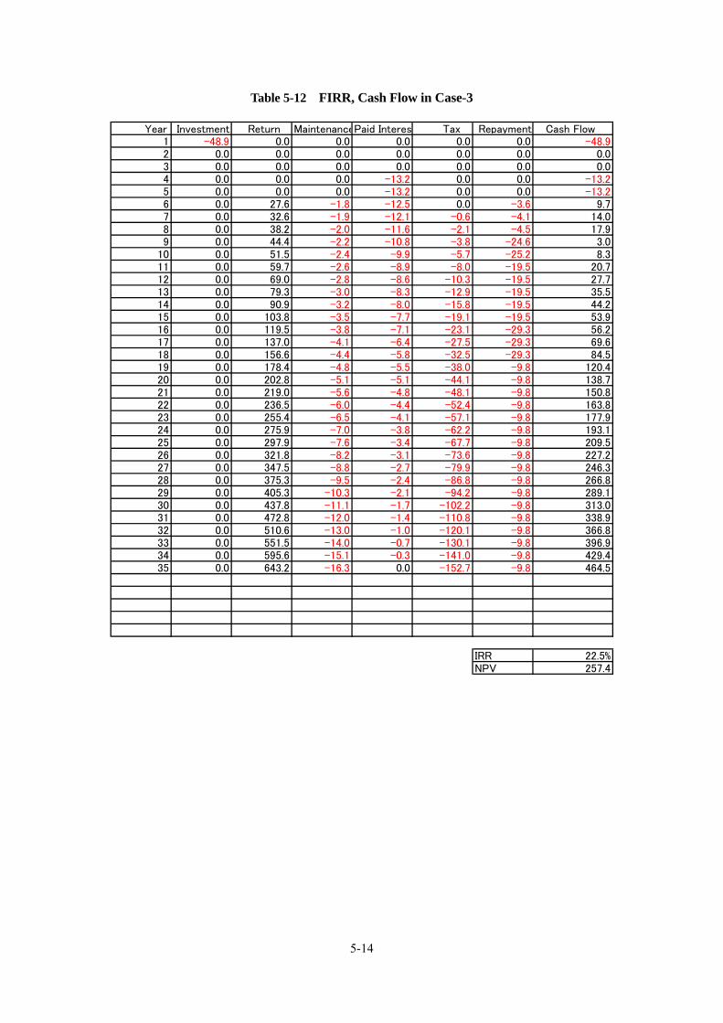
5-14
Table 5-12 FIRR, Cash Flow in Case-3
Year Investment Return MaintenancePaid Interest Tax Repayment Cash Flow 1 -48.9 0.0 0.0 0.0 0.0 0.0 -48.92 0.0 0.0 0.0 0.0 0.0 0.0 0.03 0.0 0.0 0.0 0.0 0.0 0.0 0.04 0.0 0.0 0.0 -13.2 0.0 0.0 -13.25 0.0 0.0 0.0 -13.2 0.0 0.0 -13.26 0.0 27.6 -1.8 -12.5 0.0 -3.6 9.77 0.0 32.6 -1.9 -12.1 -0.6 -4.1 14.08 0.0 38.2 -2.0 -11.6 -2.1 -4.5 17.99 0.0 44.4 -2.2 -10.8 -3.8 -24.6 3.0
10 0.0 51.5 -2.4 -9.9 -5.7 -25.2 8.311 0.0 59.7 -2.6 -8.9 -8.0 -19.5 20.712 0.0 69.0 -2.8 -8.6 -10.3 -19.5 27.713 0.0 79.3 -3.0 -8.3 -12.9 -19.5 35.514 0.0 90.9 -3.2 -8.0 -15.8 -19.5 44.215 0.0 103.8 -3.5 -7.7 -19.1 -19.5 53.916 0.0 119.5 -3.8 -7.1 -23.1 -29.3 56.217 0.0 137.0 -4.1 -6.4 -27.5 -29.3 69.618 0.0 156.6 -4.4 -5.8 -32.5 -29.3 84.519 0.0 178.4 -4.8 -5.5 -38.0 -9.8 120.420 0.0 202.8 -5.1 -5.1 -44.1 -9.8 138.721 0.0 219.0 -5.6 -4.8 -48.1 -9.8 150.822 0.0 236.5 -6.0 -4.4 -52.4 -9.8 163.823 0.0 255.4 -6.5 -4.1 -57.1 -9.8 177.924 0.0 275.9 -7.0 -3.8 -62.2 -9.8 193.125 0.0 297.9 -7.6 -3.4 -67.7 -9.8 209.526 0.0 321.8 -8.2 -3.1 -73.6 -9.8 227.227 0.0 347.5 -8.8 -2.7 -79.9 -9.8 246.328 0.0 375.3 -9.5 -2.4 -86.8 -9.8 266.829 0.0 405.3 -10.3 -2.1 -94.2 -9.8 289.130 0.0 437.8 -11.1 -1.7 -102.2 -9.8 313.031 0.0 472.8 -12.0 -1.4 -110.8 -9.8 338.932 0.0 510.6 -13.0 -1.0 -120.1 -9.8 366.833 0.0 551.5 -14.0 -0.7 -130.1 -9.8 396.934 0.0 595.6 -15.1 -0.3 -141.0 -9.8 429.435 0.0 643.2 -16.3 0.0 -152.7 -9.8 464.5
IRR 22.5%NPV 257.4

5-15
(5) FIRR in Case-4
In the Case-4, package of the project has been changed to the section from Phuc Yen –Phung
(20km)including Hong Ha Bridge and excluding the section from Trung Giat to Phuc Yen
(17km) in order to improve FIRR. But toll income has been appropriated to the project, because
the section from Trung Giat to Phuc Yen (17km) would be built under BT scheme by another
investor. This change of scheme has affected FIRR in favor , FIRR has resulted in 13.9.0%(<
12.0%).
FIRR 13.9.0%
NPV 85.6(mil USD)
Turned into profit in single year : 2020(after 5 years operation)
Turned into profit (accumulated): 2028(after 13 years operation)
Sensibility Analysis for Fluctuation of Traffic Amounts
Traffic Amounts
-20% -10% 0% +10% +20%
FIRR 11.9% 13.0% 13.9% 14.8% 15.6%
NPV(mil USD) -3.5 41.2 85.6 129.6 173.4
Financing Scheme
Terms of repayment of JICA Oversees Investment
Interest:3.5 %
Period:20 years (grace period: 10 years)
Terms of repayment:Equal principal payment
Terms of repayment of 2STEP loan
Interest:6.0 %/year (assumed)
Period:10 years (grace period :3 years)(assumed)
Terms of repayment:Equal principal payment
Construction S/V D/D O&M
Gov. Fund (VGF):30% Private Sector:70%
2STEP
Loan 40% JICA’S Investment
Toll Income
Subordinated
Interest Rate: 6..0%
Period:: 10 years
Interest Rate:3.5%
Period : 20years
Equity
Other Package
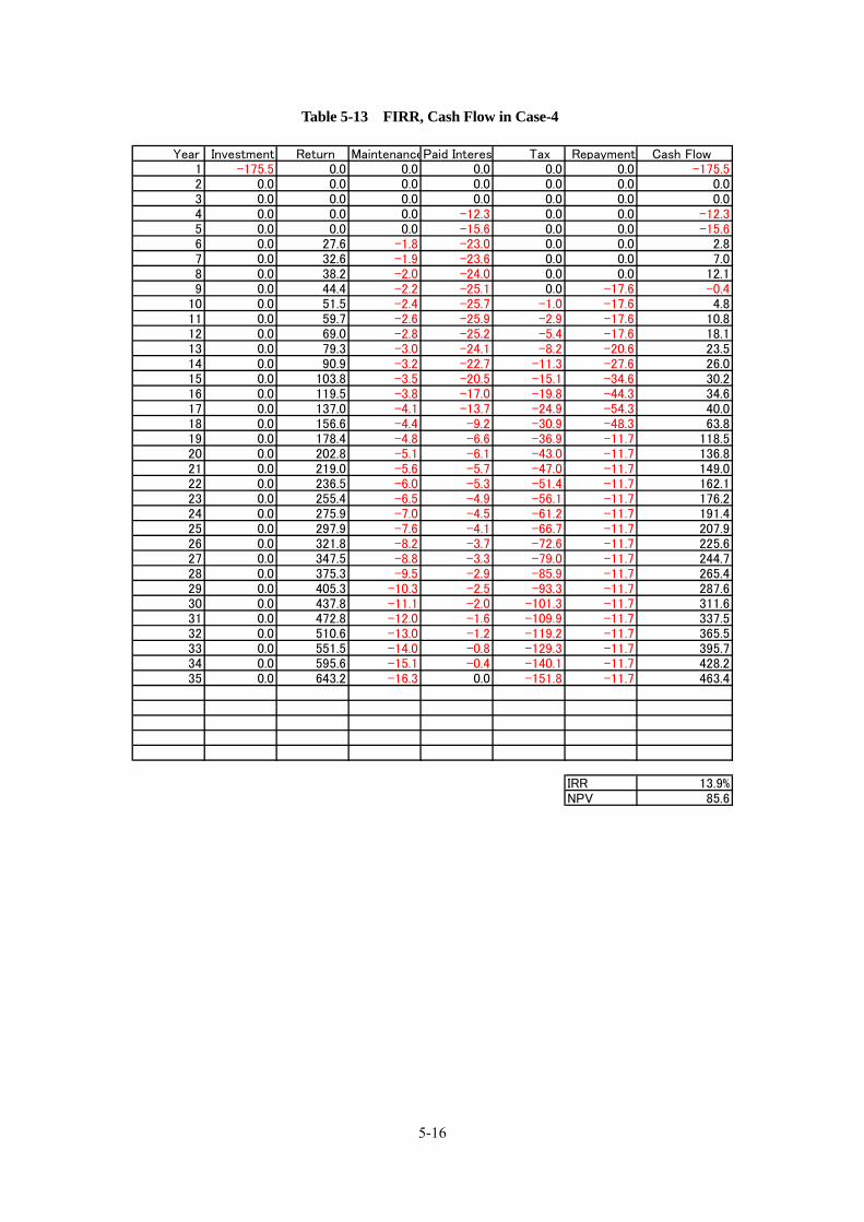
5-16
Table 5-13 FIRR, Cash Flow in Case-4
Year Investment Return MaintenancePaid Interest Tax Repayment Cash Flow 1 -175.5 0.0 0.0 0.0 0.0 0.0 -175.52 0.0 0.0 0.0 0.0 0.0 0.0 0.03 0.0 0.0 0.0 0.0 0.0 0.0 0.04 0.0 0.0 0.0 -12.3 0.0 0.0 -12.35 0.0 0.0 0.0 -15.6 0.0 0.0 -15.66 0.0 27.6 -1.8 -23.0 0.0 0.0 2.87 0.0 32.6 -1.9 -23.6 0.0 0.0 7.08 0.0 38.2 -2.0 -24.0 0.0 0.0 12.19 0.0 44.4 -2.2 -25.1 0.0 -17.6 -0.4
10 0.0 51.5 -2.4 -25.7 -1.0 -17.6 4.811 0.0 59.7 -2.6 -25.9 -2.9 -17.6 10.812 0.0 69.0 -2.8 -25.2 -5.4 -17.6 18.113 0.0 79.3 -3.0 -24.1 -8.2 -20.6 23.514 0.0 90.9 -3.2 -22.7 -11.3 -27.6 26.015 0.0 103.8 -3.5 -20.5 -15.1 -34.6 30.216 0.0 119.5 -3.8 -17.0 -19.8 -44.3 34.617 0.0 137.0 -4.1 -13.7 -24.9 -54.3 40.018 0.0 156.6 -4.4 -9.2 -30.9 -48.3 63.819 0.0 178.4 -4.8 -6.6 -36.9 -11.7 118.520 0.0 202.8 -5.1 -6.1 -43.0 -11.7 136.821 0.0 219.0 -5.6 -5.7 -47.0 -11.7 149.022 0.0 236.5 -6.0 -5.3 -51.4 -11.7 162.123 0.0 255.4 -6.5 -4.9 -56.1 -11.7 176.224 0.0 275.9 -7.0 -4.5 -61.2 -11.7 191.425 0.0 297.9 -7.6 -4.1 -66.7 -11.7 207.926 0.0 321.8 -8.2 -3.7 -72.6 -11.7 225.627 0.0 347.5 -8.8 -3.3 -79.0 -11.7 244.728 0.0 375.3 -9.5 -2.9 -85.9 -11.7 265.429 0.0 405.3 -10.3 -2.5 -93.3 -11.7 287.630 0.0 437.8 -11.1 -2.0 -101.3 -11.7 311.631 0.0 472.8 -12.0 -1.6 -109.9 -11.7 337.532 0.0 510.6 -13.0 -1.2 -119.2 -11.7 365.533 0.0 551.5 -14.0 -0.8 -129.3 -11.7 395.734 0.0 595.6 -15.1 -0.4 -140.1 -11.7 428.235 0.0 643.2 -16.3 0.0 -151.8 -11.7 463.4
IRR 13.9%NPV 85.6

5-17
(6) FIRR in Case-5
In the Case-5, in order to reduce project cost and improve the FIRR of private sector, construction
of Hong Ha Bridge would be responsible for Government utilizing JICA’s Yen Loan. And private
sector would be responsible for construction the rest of the section of 32 km and operation &
maintenance the section of 37 km. Even if when private sector would borrow project cost from
commercial banks , FIRR is considerably high , so this scheme has been found to be feasible as a
PPP scheme.If it will be possible to separate construction of the Hong Ha Bridge from PPP scheme,
the RR4 (north west part ) construction project would be attractive as BOT or BT scheme for
private sector in Vietnam and Japan .
FIRR: 14.6%
NPV: 126.7 mil USD
Turned into profit in single year: 2022( after 7 years operation)
Turned into profit (accumulated) : 2028 (after 13 years operation)
Sensibility Analysis for Fluctuation of Traffic Amounts
Traffic Amounts
-20% -10% 0% +10% +20%
FIRR 12.6 13.7 14.6 15.5 16.4
NPV(mil USD) 27.4 77.2 126.7 176.0 224.9
Finance Scheme
Terms of Repayment in ODA
Interest Rate:0.2 %/year
Period:40 years(Grace Period:10years)
Method of Repayment: Equal Principal Payment
Terms of Repayment
Interest Rate:11.0 %
Period:20years
Method of Repayment: Equal Principal Payment
Construction S/VD/DO&M
ODA
Bank Loan:: 70% Equity
Toll
Income
Subordinated
Interest Rate 12 % Interest Rate: 0.2%
Hong Ha Bridge The other Section
Construction
Private Sector: 100%
Whole
Private Sector
D/D S/V

5-18
Table 5-14 FIRR, Cash Flow in Case-5
Year Investment Return MaintenanceRepayed Interest Tax Repayment Cash Flow1 -128.7 0.0 0.0 0.0 0.0 0.0 -128.72 0.0 0.0 0.0 0.0 0.0 0.0 0.03 0.0 0.0 0.0 0.0 0.0 0.0 0.04 0.0 0.0 0.0 -9.0 0.0 0.0 -9.05 0.0 0.0 0.0 -11.4 0.0 0.0 -11.46 0.0 27.6 -1.8 -40.7 0.0 -4.2 -19.07 0.0 32.6 -1.9 -42.3 0.0 -4.7 -16.28 0.0 38.2 -2.0 -43.1 0.0 -5.2 -12.29 0.0 44.4 -2.2 -43.4 0.0 -5.9 -7.0
10 0.0 51.5 -2.4 -42.6 0.0 -6.6 -0.111 0.0 59.7 -2.6 -41.9 -0.8 -14.3 0.212 0.0 69.0 -2.8 -40.1 -3.4 -22.2 0.413 0.0 79.3 -3.0 -37.5 -6.6 -31.2 1.014 0.0 90.9 -3.2 -33.7 -10.4 -42.3 1.215 0.0 103.8 -3.5 -28.6 -14.8 -11.6 45.216 0.0 119.5 -3.8 -27.3 -19.0 -12.9 56.417 0.0 137.0 -4.1 -25.7 -23.7 -14.5 69.018 0.0 156.6 -4.4 -24.0 -29.0 -16.2 83.019 0.0 178.4 -4.8 -22.0 -34.8 -18.2 98.620 0.0 202.8 -5.1 -19.8 -41.4 -20.4 116.021 0.0 219.0 -5.6 -17.4 -45.9 -22.8 127.322 0.0 236.5 -6.0 -14.7 -50.9 -25.6 139.423 0.0 255.4 -6.5 -11.6 -56.3 -28.6 152.524 0.0 275.9 -7.0 -8.2 -62.1 -32.1 166.525 0.0 297.9 -7.6 -4.3 -68.5 -35.9 181.726 0.0 321.8 -8.2 0.0 -75.3 0.0 238.327 0.0 347.5 -8.8 0.0 -81.6 0.0 257.128 0.0 375.3 -9.5 0.0 -88.4 0.0 277.429 0.0 405.3 -10.3 0.0 -95.7 0.0 299.430 0.0 437.8 -11.1 0.0 -103.6 0.0 323.131 0.0 472.8 -12.0 0.0 -112.1 0.0 348.732 0.0 510.6 -13.0 0.0 -121.3 0.0 376.333 0.0 551.5 -14.0 0.0 -131.3 0.0 406.234 0.0 595.6 -15.1 0.0 -142.1 0.0 438.435 0.0 643.2 -16.3 0.0 -153.7 0.0 473.236 0.0 694.7 -17.6 0.0 -166.2 0.0 510.937 0.0 750.3 -19.0 0.0 -179.7 0.0 551.538 0.0 810.3 -20.6 0.0 -194.4 0.0 595.439 0.0 875.1 -22.2 0.0 -210.2 0.0 642.740 0.0 945.1 -24.0 0.0 -227.2 0.0 693.9
IRR 14.6%NPV 126.7

5-19
5.2.4 Result of calculation of Economical Internal Rate of Return(EIRR)
(1)Assumption on Calculating Economical Internal Rate of Return (EIRR)
Economical analysis aims to examine effects of the project in the aspect of socio-economical
condition, and to estimate economical relevance of the project. We have calculated EIRR, Net
Present Value (NPV) and B/C ration as indexes of the estimation.
Calculation Period : 35 years
Reduction Rate :12 %
Inflation Rate:8 %
Figure 5-3 Comparing Time and Distance with and without RR4 (north western section)
Hong Ha bridge
Phung Phuc Yen
Trung Gia
Noi Bai
Ai
NH-32
NH-18
NH-3

5-20
(2) Measurement of the Benefit through Traveling time saving
Benefit through traveling time saving has been calculated as follows;
Saved travel time = Ttraveling time from origin to destination1.(before the road construction
and improvement has not been completed )-Traveling time from origin to
detination2. (after the road construction and improvement has been completed)
Economical benefit per Vehicle = Saved travel time * Unit vehicle’s cost /hr.
Unit vehicle’s travel time cost per hour has been based on HOUTRANS “The Study on Urban
Transport Master Plan and Feasibility Study in Ho Chi Minh Metropolitan Area” (JICA 2004) and
revised on the nominal growing rate of GDP and supposed inflation rate in the future.
Table 5-15 Unit vehicle’s travel time cost per hour(USD/hour)
2002 2010 2015 2020
0.57 1.29 1.74 2.36 Vehicle
(per person) 1.76 2.59 3.81
1.12 2.53 3.41 4.63 Vehicle
( per car) 3.46 5.08 7.47
Upper:Values Based on HOUTRANS
Lower:Revised value shown upper by the nominal growing rate of GDP and supposed
inflation rate in the future.

5-21
(3) Measurement of benefit through reduction of vehicle’s operating cost
Unit vehicle operating cost (USD/car/1000km) in Table 5-15 is based on “The Study on
Southern Inter-Regional Highway including Binh Khanh and Phuc Khanh Bridge, in the Socialist
Republic of Vietnam”.
Table 5-16 Unit vehicle operating cost (USD/car/1000km)
Speed car(km/h) fixed appreciating
portionFinancial 5 575.5 32.7 542.9Cost 10 349.0 28.4 320.6
20 228.8 24.4 204.330 186.3 23.9 162.440 161.8 21.6 140.250 151.4 20.3 131.160 152.9 22.3 130.670 158.3 24.4 133.980 166.3 26.3 139.990 177.5 29.0 148.5
Economic 5 279.9 16.2 263.8Cost 10 170.1 14.1 156.0
20 111.4 12.1 99.330 91.1 11.8 79.240 79.3 10.7 68.650 74.6 10.0 64.560 75.4 11.0 64.470 72.0 12.1 60.080 81.2 13.0 68.290 86.6 14.3 72.3

5-22
(4)Result of the calculation EIRR and B/C
The results of calculation EIRR and B/C are shown in the Table 5-17, it has demonstrated an
economical effectiveness of the project. And it has been certified that the expressway of
RR4(North western section) is very useful as social infrastructure after completion of the project
period.
Table 5-17 Result of calculation EIRR, B/C and NPV
(Unit:million USD) Year Reduction Inflation Yearly Saving Time BenefitRunning cost saving Benefit Total Benefit Construction, O & M Cost Yearly Benefit
Rate Rate Simple Value Present Value Simple Value Present Value Simple Value Present Value Simple Value Present Value Simple Value Present Value
2010 100.0% 1.00 0.0 0.0 0.0 0.0 0.0 0.0 0.0 0.0 0.0 0.02011 89.3% 1.08 0.0 0.0 0.0 0.0 0.0 0.0 35.0 31.3 -35.0 -31.32012 79.7% 1.17 0.0 0.0 0.0 0.0 0.0 0.0 103.0 82.1 -103.0 -82.12013 71.2% 1.26 0.0 0.0 0.0 0.0 0.0 0.0 209.0 148.8 -209.0 -148.82014 63.6% 1.36 0.0 0.0 0.0 0.0 0.0 0.0 315.0 200.2 -315.0 -200.22015 56.7% 1.47 0.0 0.0 0.0 0.0 0.0 0.0 315.0 178.7 -315.0 -178.72016 50.7% 1.59 10.1 5.1 6.2 3.1 16.3 8.3 1.8 0.9 14.5 7.42017 45.2% 1.71 21.8 9.9 13.4 6.1 35.2 15.9 1.9 0.9 33.3 15.12018 40.4% 1.85 35.3 14.3 21.7 8.8 57.0 23.0 2.0 0.8 54.9 22.22019 36.1% 2.00 50.9 18.3 31.2 11.3 82.1 29.6 2.2 0.8 79.9 28.82020 32.2% 2.16 68.7 22.1 42.1 13.6 110.8 35.7 2.4 0.8 108.4 34.92021 28.7% 2.33 79.6 22.9 48.8 14.0 128.5 36.9 2.6 0.7 125.9 36.22022 25.7% 2.52 92.0 23.6 56.3 14.5 148.3 38.1 2.8 0.7 145.5 37.42023 22.9% 2.72 105.7 24.2 64.7 14.8 170.5 39.1 3.0 0.7 167.5 38.42024 20.5% 2.94 121.1 24.8 74.1 15.2 195.2 39.9 3.2 0.7 192.0 39.32025 18.3% 3.17 138.3 25.3 84.6 15.5 222.9 40.7 3.5 0.6 219.4 40.12026 16.3% 3.43 159.2 26.0 97.4 15.9 256.5 41.8 3.8 0.6 252.7 41.22027 14.6% 3.70 182.5 26.6 111.6 16.3 294.1 42.8 4.1 0.6 290.0 42.22028 13.0% 4.00 208.6 27.1 127.5 16.6 336.1 43.7 4.4 0.6 331.7 43.12029 11.6% 4.32 237.7 27.6 145.2 16.9 382.9 44.5 4.8 0.6 378.1 43.92030 10.4% 4.66 270.0 28.0 165.0 17.1 435.0 45.1 5.1 0.5 429.9 44.62031 9.3% 5.03 291.7 27.0 178.2 16.5 469.8 43.5 5.6 0.5 464.3 43.02032 8.3% 5.44 315.0 26.0 192.4 15.9 507.4 41.9 6.0 0.5 501.4 41.42033 7.4% 5.87 340.2 25.1 207.8 15.3 548.0 40.4 6.5 0.5 541.5 40.02034 6.6% 6.34 367.4 24.2 224.5 14.8 591.9 39.0 7.0 0.5 584.9 38.52035 5.9% 6.85 396.8 23.3 242.4 14.3 639.2 37.6 7.6 0.4 631.7 37.22036 5.3% 7.40 428.5 22.5 261.8 13.8 690.3 36.3 8.2 0.4 682.2 35.82037 4.7% 7.99 462.8 21.7 282.8 13.3 745.6 35.0 8.8 0.4 736.8 34.52038 4.2% 8.63 499.8 20.9 305.4 12.8 805.2 33.7 9.5 0.4 795.7 33.32039 3.7% 9.32 539.8 20.2 329.8 12.3 869.6 32.5 10.3 0.4 859.4 32.12040 3.3% 10.06 583.0 19.5 356.2 11.9 939.2 31.3 11.1 0.4 928.1 31.02041 3.0% 10.87 629.7 18.8 384.7 11.5 1,014.3 30.2 12.0 0.4 1,002.3 29.92042 2.7% 11.74 680.0 18.1 415.5 11.1 1,095.5 29.1 13.0 0.3 1,082.5 28.82043 2.4% 12.68 734.4 17.4 448.7 10.7 1,183.1 28.1 14.0 0.3 1,169.1 27.82044 2.1% 13.69 793.2 16.8 484.6 10.3 1,277.8 27.1 15.1 0.3 1,262.7 26.82045 1.9% 14.79 856.6 16.2 523.4 9.9 1,380.0 26.1 16.3 0.3 1,363.7 25.82046 1.7% 15.97 925.2 15.6 565.2 9.6 1,490.4 25.2 17.6 0.3 1,472.8 24.92047 1.5% 17.25 999.2 15.1 610.5 9.2 1,609.6 24.3 19.0 0.3 1,590.6 24.02048 1.3% 18.63 1,079.1 14.5 659.3 8.9 1,738.4 23.4 20.6 0.3 1,717.9 23.22049 1.2% 20.12 1,165.5 14.0 712.0 8.6 1,877.5 22.6 22.2 0.3 1,855.3 22.32050 1.1% 21.72 1,258.7 13.5 769.0 8.3 2,027.7 21.8 24.0 0.3 2,003.7 21.5
計 15,128.0 716.3 9,244.1 438.1 24,372.0 1,154.4 1,278.9 658.9 23,093.1 495.5
EIRR 16.4%B/C 1.75NPV 493.6

6-1
Chapter 6 Project Implementation Schedule
The MOT submitted a report on the section covered by this study to the Prime Minister’s Office
at the end of November and is awaiting prime ministerial approval. When the Hanoi People’s
Committee starts the project under a PPP project scheme after obtaining prime ministerial approval,
the schedule shown in Table 6-1 is conceivable. Table 6-1 shows the flow from selection of
investors to land acquisition, via the conclusion of concession contracts and detailed design, while
Table 6-2 shows the flow from detailed design and land acquisition to completion of the
construction.
Meanwhile, Hong Ha Bridge construction using a Yen loan from JICA or another agency will be
necessary in addition to the flows shown in Tables 6-1 and 6-2, if Hong Ha Bridge is constructed
using ODA financing such as funds from JICA while the remaining road sections covered by the
study are constructed by PPP contractors and these entities operate and maintain the bridge and road
sections as a whole under a PPP scheme (namely, Case 5 scheme shown in Table 5-6 in Chapter 5).
Table 6-3 shows the flow of the Hong Ha Bridge construction project using a Yen loan. In this
case, Hong Ha Bridge construction using a Yen loan and road construction under a PPP scheme
should hopefully be completed around the same time because PPP operators will have no toll income
and suffer financial loss if the completion of Hong Ha Bridge is delayed.

6-2
Table 6-1 Assumed Schedule for the Proposed PPP Project
2011 2012 Items 1 2 3 4 5 6 7 8 9 10 1112
1 2 3 4 5 6 Remarks
Submission of the PPP project by the Hanoi Authority
MPI’s judgment Announcement of the PPP project
EOI and prequalification of the companies
International competitive bidding
Acquisition of priority negotiation rights and negotiations for contracts
Conclusion of concession contracts
Detailed design and land acquisition
Approx. 10 months
Table 6-2 Implementation Schedule for Construction, etc.
Items 1st year 2nd year 3rd year 4th year 5th and subsequent years
Detailed design Land acquisition
Construction Selection of contractor
Construction: 40 months
Operation and maintenance
In the case of a BOT project, in general, the private enterprise implementing the project (SPC)
operates and maintains the road, in addition to construction of the road, in the fifth and subsequent
years until it recovers the investment.

6-3
Table 6-3 Hong Ha Bridge Construction Schedule Using Yen Loan from JICA
Items
2011
2012
2013
2014
Pre FS
SAPROF
Dispatch of JBIC appraisal mission
Pledge
Loan Agreement
Selection of consultants
Detailed design
Support for bid tendering
Start of construction
Table 6-3 assumes the earliest schedule. Bridge construction is estimated to require
approximately 40 months from start to finish. Construction of Hong Ha Bridge is believed to be the
critical element in the entire PPP project processes including construction of the road section.


7-1
Chapter 7 Implementing Organization
7.1 Overview of Implementation Agency in Partner Country The Vietnamese government decided to develop Hanoi Ring Road No. 4 as a public-private partnership
(PPP) project based on the feasibility study conducted by MOT, and the Ministry delegated the authority to
implement the project to the People’s Committee of Hanoi City. Hanoi Authority for Planning and
Investment, Hanoi People’s Committee has developed master plans, including Ring Road No. 4, and given
its past administrative experience, it is considered to have sufficient ability to implement infrastructure
development projects. In terms of PPP, however, the Committee has experience only in such projects as
waterworks and is inexperienced in road construction projects. In the case of PPP projects, the procurement
of project funds and other operations are left to the special purpose company (SPC), but the People’s
Committee is also expected to take on various risks. In particular, success in the relocation of local
residents and other operations depends largely on the skills of the People’s Committee, and in this project,
its skills will be called into question in these areas.
The People’s Committee is also expected to play a leading role in obtaining the understanding of users
when determining the amounts of toll fees.

7-2
Figure 7-1 Organizational Structure of the Hanoi People’s Committee
Government
Hani People's Committee
Long Bien District
Thanh Xuan District
Cau Giay District
Tay Ho District
Hai Ba Trung District
Ba Dinh District
Dong Da District
Hoan Kiem District
Gia Lam District
Dong Anh District
Tu Liem District
Thanh Tri District
Soc Son District
Van Xuan District
Department of Industrial and Export Processing Zone Management
Department of Trade
Department of Labour - War Invalids and Social Affairs
Department of Transportation and Urban Public Works
Department of Agriculture & Rural Development
Department of Education and Training
Department of Tourism
Department of Police Hanoi City
Department of Justice
Department of Culture and Informationa
Department of Sports and Physical Training
Department of Industry
Hanoi Authority for Planning and Investment
Department of Foreign Relations
Department of Science and Technology
Department of Finance
Hanoi Supreme Court
Hanoi Department of Tax
Department of Public Health
Department of Resources, Environment and Land Management
Department of Planning and Architect
Department of Construction
Department of Internal Affairs
Department of Telecommunication

7-3
7.2 Organizational Structure for Project Implementation in
Partner Country The Hanoi People’s Committee will implement the Ring Road No. 4 (northwestern part)
project, which covers the sector from Trung Gia, Phuc Yen toPhung, but it is customary that a PPP project is implemented by a special purpose company (SPC) established by a single private enterprise or a group of private enterprises that is chosen by the People’s Committee through international competitive bidding or similar procedures and to which the right to implement it is transferred. The typical organizational structure for a PPP project is as shown below.
Figure 7-2 Organizational Structure for PPP Projects
Special purpose company (SPC)
(Financed by a single or several
private enterprises)
Construction
companies
O&M firms
Real estate
developers
Joint venture undertaking road
and bridge construction on
contract
Banks and other
financial institutions
Hanoi People’s Committee
InvestmentInvestments and loans
Investments, subsidies, and
service purchasing funds
Concession agreement
O&M firms
(Outsourcing agreements on fee
collection and maintenance)


8-1
Chapter 8 Technical Advantages of Japanese
Companies
8.1 Expected Forms of Participation by Japanese Companies This field survey is conducted for a JPY 88 billion PPP project, which includes the construction of
a 37-km expressway and its maintenance. Vietnam has practically no experience in the operation and
maintenance of expressways. As it is anticipated that the age of fully-fledged expressways will
arrive in the country in the future, private enterprises with experience in expressway operation and
maintenance utilizing advanced ITS technology are expected to participate in the project. At present,
Vietnam has not only this but also many other expressway construction projects, and for all these
projects, advanced traffic safety management measures can be taken and a wide range of toll fee
collection systems adopted. And making the most of ETC facilities that do not require cars to stop
for toll fee collection or fail to collect toll fees is one of the issues to be addressed in these projects.
The know-how accumulated by Japanese expressway companies through the operation and
maintenance of about 9,000-km high-standard arterial roads is expected to provide a standard for
solving these issues in Vietnam. In order to ensure that Japanese expressway companies and their
group companies fully demonstrate their know-how in operation and maintenance services, it is
desirable that they participate in the project as an entity that implements it. To that end, Japanese
companies should invest in the special purpose company (SPC) for the project and provide toll road
operation and maintenance services as part of the entity, and by doing so, they will be able to
establish a safe and secure expressway operation and maintenance system based on Japanese
standards in Vietnam. Expected specific forms of participation by Japanese companies in operation
and maintenance as well as construction work are shown in the table below.

8-2
Table 8-1 Participation by Japanese Companies in Operation and Maintenance
Participating
companies
Form of participation Roles, etc. Remarks
Expressway companies Investment in SPC Acceptance of orders
for operation and
maintenance services
Joint ventures with
Vietnamese companies
Banks and other
financial institutions
Investment in SPC Sales of ETC cards
Electric manufacturers,
etc.
Selling facilities and
instruments for
operating expressway
in Vietnam
- Sales of ETC system
equipment (such as
on-board devices)
- Sales of traffic
guidance and
information systems
Table 8-2 Participation by Japanese Companies in Road and Bridge Construction
Participating
companies
Form of participation Roles, etc. Remarks
General contractors Investment in SPC Acceptance of orders
for bridge construction
Joint ventures with
Vietnamese companies
Consulting firms Order from detailed
design and supervising
of construction works,
assistance for
implementation of the
project
Detailed design of
bridges and other
structures as well as
supervision of
construction work
Steel makers, etc. Sales of steel pipe
sheets, cables, and
weatherproof steel
materials

8-3
8.2 The advantages afforded by Japanese technologies
The route covered by this project extends a total of 37 kilometers and will cost 1.1 billion USD to
construct. The project scope covers the construction of a cable-stayed bridges with center span
length of 370m or an extradosed bridge which will have 6 continuous span with length of 210m, and
for which it is anticipated that Japanese materials, design and construction technologies will be
utilized.
The site at which this bridge to be constructed is located in the Red River Delta, and there is layer
of soft soil ground with an SPT N-value approaching zero that extends to a considerable depth. The
construction of the substructures is thus expected to be difficult and demanding.
The Red river to be spanned by this bridge is about 5,000m in width. It will therefore be necessary
to ensure that river traffic is subject to minimal disruption during construction.
In recent years, the costs involved in the maintenance of bridge superstructures have begun to be
assessed in terms of life cycle costs, and the weather-resistant steel that is being employed in many
steel bridges in Japan, is considered to represent one example of this trend.
In consideration of all these factors, it is anticipated that the following Japanese technologies will be
employed in respect of the construction methods, materials and equipment used in the construction. ・ The design, construction and wind tunnel testing of cable-stayed bridges
・ Substructure construction techniques which minimize obstruction to ship navigation: design
and construction of steel pipe sheet pile foundation
・ Weather-resistant steel
・ Steel pipe sheet pile
・ Cable-stayed bridge cables
・ Expansion joints, bearings and other ancillary parts
・ Maintenance facilities, including inspection travelers, etc.
・ Various construction machinery
Simple explanations of the above are provided below.
(1) The design, construction and wind tunnel testing of cable-stayed bridges
Cable-stayed bridge is a statistically indeterminate structure and the design solution lies in
achieving a balance between girders, towers and cables. Japan has a proven track record in the
construction of cable-stayed bridges and is capable of creating the most rational and
aesthetically-pleasing designs.

8-4
Moreover, it is recommended that the balancing cantilever erection method be employed in order
to maintain reasonable construction duration and costs. However, since this necessitates step-by-step
analysis to confirm the safety of girders, towers and cables, any discrepancy in analysis and site
conditions could jeopardize both safety of construction works and the structure per se. By
introducing Japan’s proven record in the use of the balancing cantilever erection method, it will be
possible to complete the entire process safely, from analysis through construction.
In addition, wind tunnel testing is necessary to confirming the wind stability of the structure both
during and after construction, and Japan’s wealth of experience and achievements in this area will be
of benefit in the design and construction of the Hong Ha Bridge.
YOKOHAMA BAY Bridge (JAPAN) Span: 200 + 460 + 200 Tower: Steel
TSURUMI TSUBASA Bridge (JAPAN) Span: 255 + 510 + 255 TToowweerr:: SStteeeell
TATARA Bridge (JAPAN) Span: 270 + 890 + 320
TToowweerr:: CCoonnccrreettee GGiirrddeerr:: SStteeeell BBooxx ((CCeenntteerr))
SStteeeell ++ PPCC ((SSiiddee))

8-5
(2) Steel pipe sheet pile foundation engineering
More than 2,000 steel pipe sheet pile foundations have been built in Japan, and the techniques
employed make it possible to build these foundations in very deep waters or on soft soil ground
without the need for cofferdams, pneumatic caissons or other structure for underwater construction.
The design and construction techniques employed in this technology have been developed by five
Japanese steel manufacturers with grant funding provided by the Ministry of Construction,Japan and
it outranks the concrete caisson foundations formerly used in road and rail bridges in terms of
scheduling, costs and work safety.
A structural overview of the steel pipe sheet pile foundations is given in Figure 8-1.
Small-diameter steel pipes form a coupler arrangement on both sides of a circular steel pipe,
which is then filled with mortar to form highly rigid foundations. This will be the second time for the
technology to be employed on a Japanese project overseas, though the technology was used in
Vietnam in the construction of the foundations for the Nhat Tan Bridge.
Figure 8-1 Schematic view of steel pipe sheet pile foundation

8-6
The number of steel pipe sheet pile foundations built in Japan is given in Fig. 8.2.
Figure 8-2 Yearly Construction of Steel Pipe Sheet Pile Foundations
The application in Mihara Bridge in Hokkaido is shown in Figure 8.3 as an example of the use of
these foundations in a large-scale cable-stayed bridge.
Figure 8-3 Mihara Bridge

8-7
(3) Cable-stayed bridge cables
Prefabricated parallel wire strand cables are widely used in cable-stayed bridges in Japan. There
are several reasons for this, as follows. A polyethylene layer is formed using extrusion molding process thus ensuring the reliability
of cable waterproofing and durability, which are essential to maintenance.
The use of wire with a tensile strength of 180 Kgf/mm2 made it possible to reduce the
cross-sectional area of the cables, of which wire was used in the Akashi-Kaikyo Bridge and
Kurushima-Kaikyo Bridge.
Indent processing of the coated surface allows for the selection of cables that are capable of
withstanding rain-wind induced vibration, etc. Given that the Hong Ha Bridge will have a
center span of 370m, permanent vibration countermeasures for wind stability must be taken
into consideration and, given their proven record in Japan, it is therefore recommended that
the cables described above be used.
Figure 8-4 Prefabricated Parallel Wire Strand and Indented Surface Treatment
IInnddeenntt CCaabbllee iinn TTAATTAARRAA BBrriiddggee

8-8
(4) Steel pipe sheet pile
The concept of utilizing steel pipe sheet pile for deep-water revetment earth retaining work was
developed in Japan. A P-P joint which couples small-diameter steel pipes and filled with mortar to
improve the rigidity of the foundations was devised. Japan is the only country to have the product
specification for steel pipe sheet pile, and its JIS 5530 is becoming the standard in Japan. The steel
pipe sheet pile is long and must ultimately be amalgamated, and with its rigorous standards of
accuracy required, this product promises to deliver Japanese manufacturing expertise.
(5) Weather-resistant steel
Weather resistant steels have a unique property in that they use rust to prevent corrosion, and they
are now widely employed in numerous structures, including bridges. Moreover, there are numerous
examples of structures in Japan and overseas, in which this property has been harnessed to help
reduce maintenance costs.
In Japan, weathering resistant steels have proved particularly popular with local governments and
there are some prefectures in which the proportion of bridges using this steels approaches as much as
80%.
The development of weather-resistant steel bridges in Japan has some notable aspects. The
decision as to whether to apply weathering resistant steels was formerly based solely on air-borne
salt measurements, but a method for estimating corrosion depletion that factors in both wetness
duration and temperature, etc. has been developed and a simple site test procedure put forward.
Performing this simple site test at the planned construction sites for the two bridges will confirm the
applicability of weather resistant steel and allow for the life cycle costs (LCC) of the bridges to be
investigated as part of the detailed design. Since this site test was not undertaken in this Feasibility
Study, regular steel is used for cost estimation.
In technological terms, weather resistant steels comprise rolled steel for welded structures to
which cupper (Cu), nickel (Ni), chrome (Cr), and phosphorus (P) have been added. The first edition
of “JIS G3114 hot-rolled atmospheric corrosion resistant steels for welded structures” was
established in the Japan Industrial Standards, published 1968, and this classification being refined in
1983 to include paint-less weather resistant steel (SMA-W).

8-9
Figure 8-5 Trend of Weather Resistant Steel
0
30
60
90
120
150
S53 S55 S57 S59 S61 S63 H2 H4 H6 H8 H10 H12 H14
年度
鋼重
(千
トン)
0.0
5.0
10.0
15.0
20.0
25.0
鋼橋
に占
める
比率
(%
)鋼重(千トン)
全鋼橋に占める比率(%)
Photo 8.1 February 1982 (2 months after completion)
Photo. 8.2 January 1999 (17 years and 1 month after
completion)
Stee
l Wei
ght (
‘000
tons
)
Rat
io in
Ste
el B
ridge
s (%
)
1978 1980 1982 1984 1986 1988 1990 1992 1994 1996 1998 2000 2002
Year
Steel Weight (‘000tons)
● Ratio in Steel Bridges

8-10
8.3 Measures Necessary to Enhance Competitiveness of
Japanese Companies 8.3.1 Systems to Subsidize Costs Required for Participation in International Competitive Bids
In order for Japanese companies to win an order for a PPP project, it is extremely advantageous to
participate in the entity that implements the project by investing in the project’s special purpose
company (SPC), which serves as the entity, if, for example, the project is carried out using a BOT
scheme. The reason is that this form of participation allows Japanese companies to participate in the
definition of specifications and the setting of prices actively. Therefore, in order to help them to win
an order for such a project, it is extremely important to encourage them to participate in the project
as a member of SPC first by investing in it.
The fact is, however, that in the past, Japanese construction companies have expanded into
overseas markets mainly through ODA-based yen-loan or grant-aid projects, and that such expansion
has been limited to relatively low-risk areas as when, based on general contracts, they won orders for
construction projects in Japan. In addition, Japanese expressway companies, which undertake the
operation and maintenance of almost all expressways in Japan, have no track record of operation and
maintenance in overseas countries because only several years have passed since they were
established through privatization. For this reason, they have to overcome considerably difficult
obstacles when participating in an overseas PPP road construction project that involves investing in
an SPC; placing orders for, supervising, and completing construction work within the framework of
unfamiliar local legal systems as an entity that implements it; and recovering the invested funds by
collecting toll fees.
In Vietnam, contractors will be chosen through international competitive bids in the future when
participating in PPP projects, and therefore, Japanese companies need incentives for participating in
such international competitive bids.
Survey expenses incurred when a Japanese company expresses its intention to participate in a PPP
road project in Vietnam and joins an international competitive bid are several to tens of times larger
than when it expresses its interest in an ordinary project to be implemented by contract and offers a
tender, and measures for covering such bidding expenses are needed to encourage Japanese
companies to join international competitive bids in Vietnam.

8-11
European and North American governments or their agencies have a system to pay expenses
incurred when private enterprises offer a bid for construction projects that require an extremely high
level of or highly specialized technology. The Vietnamese government is expected to establish such
a system to ensure the appropriate competitiveness of bidding and choose reliable private enterprises
as PPP contractors.
Currently, JICA conducts preliminary surveys for infrastructure projects each year, but it is
desirable that the Agency should carry out such surveys for a wider range of projects so that the
periods during which it conducts such surveys are linked to those during which partner countries
express their interest in international competitive bids and invite tenders for their projects.
8.3.2 Funds for Bidding Expense Subsidy System
Essentially, the Vietnamese government should nail down a budget for each of its PPP projects to
take measures for ensuring their fairness, transparency, and competitiveness, and publicly announce
such measures when inviting tenders for each of its PPP projects. Since it is difficult to expect the
Vietnamese government to take such measures actively under the current financial circumstances,
however, a system will be necessary in which, for instance, the Japanese government lends such
funds to its Vietnamese counterpart.
In PPP projects, there are cases in which a private enterprise that eventually enters into a
concession agreement with the government covers part of the expenses of other enterprises that lose
in the competitive bidding, but this method should be avoided because it may hinder fair
competition.
Another way to reduce the survey expenses of private enterprises rather than help with such
expenses is for competing private enterprises to cut down on survey expenses and lighten human
burdens by conducting surveys jointly and sharing their expenses if necessary data are not available.

8-12
8.4 Japanese Company’s Image in the Special Purpose
Company established in Vietnam
When Japanese company will participate in the project, an image for implementation system of the
project is shown in Fig. 8.6. It corresponds to the PPP scheme, of which has been referred to Case 5
and estimated better in the FIRR analysis. In the Case 5 , Vietnamese government will construct
Hong Ha Bridge with ODA loan, while PPP investor will construct expressway section with length
of 32km, and then PPP investor will operate and maintain whole section of expressway including
Hong Ha Bridge. Of course Government will lend Hong Ha Bridge with no charge to PPP investor
during business period. It would be referred to as “ PPP scheme combined ODA scheme”.
Figure 8.7 shows an image of project implementation system under PPP scheme as usual.
The image of project implementation system in Fig 8.6 and 8.7 has been planed based on the results
of the interview study for the Vietnamese officials MPI, MOT, Hanoi Authority for Planning and
Investment and officials in Vietnamese private companies such as Him Lam Corporation, BITEXCO
and VINACONEX. And it has been confirmed to be valid according to the law in Vietnam.

8-13
Figure 8-6 Project Implementation System in Case 5
Hong Ha Bridge Construction ( 5km) Yen Loan Project(STEP)
Road Construction under PPP Scheme (32km)
Vietnam HPC or MOT
HPC
SPC Japanese Share 51% (NEXCO Companies and , General Contractors ) Vietnamese Share 49%
Joint Venture of the Japanese Companies
JICA
ODA, Yen Loan (STEP)
Completed Hong Ha Bridge (L=5km)
Completed Expressway (L32km)
Japanese NEXCO Section 37kmExpressway O & M Orders from SPC
Bank Loan
Construction Contract
Customers
Pay toll Services Expressway
Road Const. J.V. Toll Revenue
Contract O&M
Construction Contract
Concession Contract

8-14
Figure 8-7 Project Implementation system under PPP scheme as usual
Established SPC Japanese Companies Share 51 %Vietnamese panies Share 49%
MPI or MOT
HPC
Banks, Pubic Loan
from W.B,ADB and
JICA and Overseas
Hong Ha Bridge Const. JV (Japanese bridge makers and General Contractors)
Road Const. JV Vietnamese (General Contractors etc)
O & M Orders
Japanese NEXCO,etc.
Completed Hong Ha Bridge
Completed
Expressway
Supervision
Concession Contract
Const. Contract
Loan
Operation &
Maintenance
Contract orders
from SPC
Const. Contract
Expressway Services Pay Toll
Toll
Revenue
Japanese Companies:
General Contractors,
Bridge Fabricators,
NEXCO etc.,
Customers

9-1
Chapter 9 Financial Outlook
9.1 Examination on Funding Resource and Financing Plan
○ Prerequisites of the examination
・Prime Minister’s Decision No. 71/2010/QD-TTg dated November 9, 2010 provides for PPP pilot
projects.
・The principle of VGF is set as within 30% of the amount invested in the relevant project, but over
30% VGF may be possible depending on details of the project.
・VGF includes the right to use (acquire) land. The government (ministries and municipalities ruled
by the central government) will be in charge of negotiation with right holders.
・Proposed project includes construction of Hong Ha bridge, which require huge cost. VGF shall
be expected to cover 30 % of project cost in case of using PPP scheme.
・World Bank will provide financing to Vietnamese local companies in dollars as for road project by
PPP, according to interview with Vietnamese PPP operators.
○View on funding resources
・Use of low-interest public loans such as JICA Overseas Investment was assumed because loans
from commercial banks will not afford the project even if VGF is 30% of the project cost.
・In an interview with a Vietnamese government agency, many officials expressed their views that it
may be difficult to construct Hong Ha Bridge under a PPP project scheme because of the huge
cost. The Vietnamese government hopes to use a Yen loan for Hong Ha Bridge and is examining
a plan assuming a Yen loan. (Case 5 in Chapter 5)

9-2
9.2 Feasibility of Financing
・It is expected that low-interest public loans will be applied to projects in Vietnam including the
road BOT project between Dau Giay and Phan Thiet. Therefore, this project will possibly use
such a loan.
・A method of reducing the government’s real financial burden and hedging risks of private
companies by a BT(Built Transfer)scheme is used for other sections of RR4. In this section
including Hong Ha Bridge, however, implementation only by a BT scheme will lead to
imbalance, so it will be necessary to secure the stability and safety of the Project by combining
schemes such as the “PPP+BT” scheme. Case 4 is examined in Chapter 5 because the
participation of Vietnamese enterprises will allow reduction of project risks and the financing
feasibility will increase by proposing a scheme that is more accessible for Vietnamese companies
showing high interest in the Project.
・It is necessary to clarify the exit strategy for startup (investment) by Japanese companies, etc.
Traffic volume and toll income are expected to increase substantially with the development of
Hanoi. Prospects for buyout after opening of the road will reduce obstacles for investment.

9-3
9.3 Analysis of Cash Flow
9.3.1 Precondition
・Calculation of the FIRR has been conducted after setting conditions based on indices as mentioned
in chapter 5.
discount rate 12.0%
inflation rate 8.0%
period 30 – 40 years
toll fee 5 cent/ km(900 Dong)January 2011
revised at inflation fluctuation
maintenance cost 20,000 Dollars/ km/ year
dividend to SPC None (retained earnings assumed as profit)
Figure 9-1 Assumed Project Scheme
SPC Invester lender
Vietnam
Investment(21%) lending(49%)
VGF (30%)
Concession Agreement
Design Company Construction
Company
O&M Company
Constract of Design, Construction
Constact of O&M
Road user
Toll fee

9-4
Figure 9-2 Financing method (case 2)
Terms of repayment of JICA Oversees Investment
Interest:3.5 %
Period:20 years (grace period: 10 years)
Terms of repayment:Equal principal payment
Terms of repayment of 2STEP loan
Interest:6.0 %/year (assumed)
Period:10 years (grace period :3 years)(assumed)
Terms of repayment:Equal principal payment
Table 9-1 Forecasted traffic volume and revenue from toll fee
Traffic(1000veh) Revenue from toll fee
remarks
①NH3-NH2 ②NH2-NH32 mil USD
2015 15.9 22.5 17.9
2020 25.1 33.1 37.9
2025 34.1 45.6 72.9
2030 45.1 60.9 136.0
Construction S/V D/D O&M
Public (VGF):30% Operator :70%
2STEP Loan 30%
JICA Overseas Investment: 40% Equity 30%
Toll incomesubordinated
Interest: 6.0%Period:10 years
(grace period :3 years)
Interest:3.5 % Period:20 years
(grace period: 10 years)

9-5
9.3.2 Result of Case Flow Analysis
Table 9-2 below shows the results of cash flow analysis based on the most standard pattern (Case
2). The project is not sufficiently attractive for private companies to invest in although FIRR is over
12.0%. If traffic value decreases 20%, the Project becomes unfeasible. (Chapter 5 examines other
patterns to improve the profitability in this regard.)
Table 9-2 Financial Cash Flow (Case 2)
事業年度 出資 収益 維持管理費 支払利息 法人税 借入金返済 キャッシュフロー1 -205.2 0.0 0.0 0.0 0.0 0.0 -205.22 0.0 0.0 0.0 0.0 0.0 0.0 0.03 0.0 0.0 0.0 0.0 0.0 0.0 0.04 0.0 0.0 0.0 -14.4 0.0 0.0 -14.45 0.0 0.0 0.0 -14.4 0.0 0.0 -14.46 0.0 27.6 -1.8 -25.5 0.0 -1.7 -1.37 0.0 32.6 -1.9 -25.3 0.0 -1.9 3.58 0.0 38.2 -2.0 -25.1 0.0 -2.1 8.99 0.0 44.4 -2.2 -23.6 0.0 -22.9 -4.2
10 0.0 51.5 -2.4 -22.0 -1.1 -23.2 2.811 0.0 59.7 -2.6 -20.5 -3.5 -23.5 9.712 0.0 69.0 -2.8 -18.9 -6.1 -23.9 17.313 0.0 79.3 -3.0 -17.3 -9.1 -24.3 25.714 0.0 90.9 -3.2 -15.6 -12.3 -24.8 35.015 0.0 103.8 -3.5 -13.8 -15.9 -25.3 45.316 0.0 119.5 -3.8 -11.6 -20.3 -34.2 49.617 0.0 137.0 -4.1 -9.8 -25.1 -34.2 63.818 0.0 156.6 -4.4 -8.1 -30.3 -34.2 79.519 0.0 178.4 -4.8 -7.7 -35.8 -13.7 116.520 0.0 202.8 -5.1 -7.2 -41.9 -13.7 134.921 0.0 219.0 -5.6 -6.7 -46.0 -13.7 147.122 0.0 236.5 -6.0 -6.2 -50.4 -13.7 160.223 0.0 255.4 -6.5 -5.7 -55.1 -13.7 174.424 0.0 275.9 -7.0 -5.3 -60.2 -13.7 189.725 0.0 297.9 -7.6 -4.8 -65.7 -13.7 206.226 0.0 321.8 -8.2 -4.3 -71.6 -13.7 224.027 0.0 347.5 -8.8 -3.8 -78.0 -13.7 243.228 0.0 375.3 -9.5 -3.4 -84.9 -13.7 263.929 0.0 405.3 -10.3 -2.9 -92.3 -13.7 286.230 0.0 437.8 -11.1 -2.4 -100.4 -13.7 310.231 0.0 472.8 -12.0 -1.9 -109.0 -13.7 336.232 0.0 510.6 -13.0 -1.4 -118.4 -13.7 364.233 0.0 551.5 -14.0 -1.0 -128.4 -13.7 394.434 0.0 595.6 -15.1 -0.5 -139.3 -13.7 427.035 0.0 643.2 -16.3 0.0 -151.0 -13.7 462.2
IRR 13.2%NPV 59.6
・
year investment revenue O&M cost interest CIT repayment Cash flow

9-6
○ Sensibility Analysis for Fluctuation of Traffic Amounts
Traffic Amounts
-20% -10% 0% +10% +20%
FIRR 11.4% 12.3% 13.2% 14.0% 14.8%
NPV(mil USD) -29.4 15.3 59.6 103.9 147.7

10-1
Chapter 10 Action Plans and Issues for PPP
Projects
10.1. The situation regarding implementation of this project
The status of the 37km of Hanoi Ring Road 4 (northwestern section) is that the final feasibility
study report was submitted by the MOT to the office of the prime minister on November 30th, and
the project method etc. awaits the decision of the prime minister. Concessions for the adjacent
section south from Hung to National Route 1A have already been granted to two private-sector
contractors as BT contractors, so it appears likely that the policy for this section will basically be to
apply a PPP project scheme. Also, Decree 71 was promulgated on November 9th, setting the new
legal framework for PPP projects. It determines the selection of PPP pilot projects, the international
competitive tendering to be used if selection of PPP contractors is required, and the rule that the
government’s investment and subsidies must be less than 30%. It covers these matters for all future
development of PPP projects.
According to the content determined by the decree, the first step towards the Hanoi RR4 project to
be adopted as a PPP pilot project is for it to be raised as a candidate with the Hanoi People’s
Committee and undergo MPI scrutiny. This study is positioned on the assumption that the project
will be raised with the Hanoi People’s Committee.

10-2
10.2. Measures which will be necessary for the implementation of this project
10.2.1. Investment in the Vietnamese government’s VGF
The 37km length of Hanoi Ring Road 4 (northwestern section) includes the Hong Ha Bridge,
which will be very expensive to build, so this project would appear to present high hurdles for
private-sector investors. The reasons are stated below. [1] Compared to adjacent sections, the
project cost will be approximately 50% higher. [2] Passage tolls are set by decree of the Ministry
of Finance, so there is no flexibility for the contractor. [3] Traffic flow forecast survey results
exist, but there is likely to be resistance to tolls, so the survey results come with a large element of
risk.
For private-sector contractors to express an interest in this project after considering these risks,
it appears that there would have to be substantial financial support from the government and
elsewhere. If the Vietnamese government had a systematic PPP support policy by which the
Vietnamese government would pay for VGF and the funds would be covered by investment from
the Japanese side, it would be a strong incentive for Vietnamese private-sector contractors, and for
the Japanese companies which would partner with them.
At present Decree 71 stipulates that the government’s contribution, including VGF, to any
individual PPP project must be less than 30%, including land acquisition costs, but it is important
for the government and contractors to come to an accommodation on each project, so exceptional
rules should be applied flexibly.
10.2.2. The establishment of objective assessment criteria for international competitive
tendering on the Vietnamese side
Decree 71, which was promulgated on November 9th, declares, both in Vietnam and overseas,
that international competitive tendering will be used as the selection method for PPP contractors,
using a method of high fairness and transparency. This should be noted as a major step forward.
However, considering the fact that PPP projects are very different from cases of private
companies contracting for public works projects, it is necessary to set assessment criteria to
determine rankings. Those assessment criteria must be acceptable to the private-sector contractors
as appropriate. The Vietnamese government must urgently determine the assessment criteria.

10-3
10.2.3. Flexible application of BT and BOT schemes
The Hanoi People’s Committee has contracted concessions with private companies for the
construction sections adjacent to the area surveyed, between Hung and the National Route 6
intersection (six lanes, 20km long) and between National Routes 6 and 1A (six lanes, 17km long).
Both are BT schemes.
A BT scheme is one in which the private-sector contractor builds the road at its own expense,
and is granted the land by the government (transfer of land rights) in return. The outskirts of
Hanoi are close to the capital, so there are many suitable sites for residential land, industrial parks
and resort areas. For realty developers, BT schemes are highly attractive because they are exposed
to little market risk. However, BT projects are based on the assumption of permanent use of the
land, so there is a restriction that foreign companies cannot participate. In the PPP schemes now
under consideration, most are BOT schemes, but for investment values that will not be covered by
fee collection, the use of a scheme mixing BOT and BT aspects, in which land on the outskirts of
Hanoi would be transferred in payment, would be a very useful method in Vietnam.
This is not possible under the current legal framework, but it appears that partial revision of the
law might be possible, and that is a matter for future research. If it were possible, a new Decree
could be issued or the existing one amended, and them it would become quite feasible to go
forward with such a scheme in the survey area.
10.2.4. Toll policy, taking other road tolls into account
The issue of how to set passage tolls is one of the most important for the private-sector
contractor of a toll road under a PPP scheme. For a route substitution road project such as RR4,
there is the risk that potential users will not use the road, even if it is highly convenient, if they
feel that the toll is too high. For a road that is built to alleviate congestion, it becomes necessary to
adopt a comprehensive pricing policy that makes users keen to use the road, taking into account
the tolls and convenience of other roads. In short, toll policy is an important measure affecting the
extent to which toll resistance can be overcome. Specifically, the toll setting must take into
account the tolls on the Nhat Tan Bridge and the Thang Long Bridge, which will be completed in
future.
Other than those considerations, the inflation rate in Vietnam is high, so it appears necessary to
have a system for revising tolls every few years, in linkage with the inflation rate.

10-4
10.2.5. Measure for Delay of land acquisition
In Vietnam, delay of land acquisition often happens, which is obstacle for construction. This has
effects Nhat Tan Bridge construction. The delay can be big obstacle for participation of foreign
investors without appropriate countermeasure, including penalty for government.

10-5
10.3. Specific Action Plan and Issues for the Implementation of This Project
In January 2011, we made case-by-case proposals for a number of PPP schemes for this project,
ran financial analyses and explained the results to key related local agencies. The case-by-case
PPP schemes included proposals for cases in which the government’s financial investment,
subsidies and other expenditures on a PPP project would exceed the regulation maximum of 30%
which is stipulated in “Decision 71”, the legal framework for PPP projects approved by the prime
minister on November 9th, 2010. In one case, VGF was set at 50%, as an exceptional measure.
At the report meeting in Viet Nam. the MPI took a negative stance on exceptional payments in
excess of 30%, on an emergency basis, from VGF for PPP projects. Among the schemes
considered, there was a positive attitude to the scheme in which the government would build the
Hong Ha Bridge as an ODA project and contribute to the PPP contractor which builds the road
portion, after which the PPP contractor would be responsible for unified operation and
management. PMU2 was also favorable to that scheme, and commented that its attitude was the
result of consultations with the MPI and MOT. If the Hong Ha Bridge was implemented as a Yen
loan project and the operation management was a PPP project, that would accord with the
Vietnamese side’s desire to gain new technology in expressway operation management. To that
end, it will be necessary to proceed with developing the environment for working with the focus
on that scheme.
10.3.1 Action Plan and Issues on the Vietnamese Side
The steps that should be taken by the Hanoi People’s Committee as the client for this project
are to submit this project to the MPI as a candidate PPP project and obtain the MPI’s approval,
and at the same time, lobby the Japanese side to adopt the Hong Ha Bridge as a JICA Yen loan
project. The most important point for implementing this projects as a PPP scheme is to work
through those two actions in parallel.
The Vietnamese side can decide independently on proposing the project as a PPP project, MPI
adoption and related issues, but at the same time, the completion of the Hong Ha Bridge as a Yen
loan project is the key point of the scheme, so the most important task is to strongly press the
Japanese slide to raise the priority of Hong Ha Bridge as a Yen loan project.
The environmental study is at the initial environmental survey stage, so another procedure the
Vietnamese side should be working on is to start the EIA procedure early and obtain EIA
approval.

10-6
10.3.2 Action Plan and Issues on the Japanese Side
On the Japanese side, a private-sector operator interested in the PPP project would probably
find it an effective choice to use a JICA PPP infrastructure project preliminary survey to fill out
the content of this study. If the operation management will be handled by a Japanese company, the
company’s expenses will unavoidably have to be covered by transport toll revenues. The issues
that should be investigated by the PPP infrastructure project preliminary survey are as follows;,
① whether it will be possible to arrange a hedge against traffic demand risks, such as a
government-guaranteed minimum traffic volume revenue or not ② whether it will be possible
to hedge against traffic demand forecasting risks with the method of distributing the traffic
volume revenue within the SPC or not.

10-7
10.4. Results of the PPP Project Fact-finding Survey in Vietnam
The Study Team performed an interview survey by visiting private-sector companies in Viet
Nam with experience or current operations in BOT or BT projects, to ask about their company
summaries, business content, funding procurement, traffic volumes, future outlook and other matters.
The results are as stated below.
10.4.1. BITEXCO (Binh Minh Production Management and Import/Export Company),
Hanoi Office
Date and time: December 3rd, 2010 (Friday) 09:00-10:30
Interviewed personnel: Financial Investment Director
Infrastructure Development Department
Proceedings:
The aim of the survey team was to investigate making a 37 km section of RR4 (northwest side) into
a PPP project, and in order to study the project scheme, a fact-finding study was performed to draw
on the PPP experience of the relevant staff at BITEXCO, a company with experience of PPP projects
in Viet Nam.
The survey team explained its aims at the meeting. The Financial Investment Director gave the
following explanation:
* BITEXCO is a 100% private-sector company, and its four main types of business are realty,
infrastructure development, hydroelectric power generation and mineral extraction. Its realty
operation is top class, even by Vietnamese standards.
Examples of BOT project implementation
[1] National Route 1 bypass toll road
* The bypass toll road is 10-km long for National Route 1 in Thanh Hoa province, with one lane
in each direction, and is now in service under a BOT scheme. The project cost was USD50
million (including land compensation costs). The toll collection period is 27 years, starting from
January 2009. Project revenue only comes from tolls. Traffic flow is currently 9,000 vehicles a
day (2% above the forecast). The route includes six bridges of various sizes. Land is used free of
charge by the contractor, at government expense.
* As the project is a BOT scheme, tolls for four-wheeled passenger vehicles are set at
VDN20,000, according to Ministry of Finance regulations (administrative ordinance No. 78).

10-8
Motorcycles do not pay tolls. The tollgate is installed on NH1 (tolls are also collected from
vehicles traveling on NH1).
[2] Between Dau Giay and Phan Thiet (BOT project under negotiation)
* Four lanes in each direction between Dau Giay and Phan Thiet, a total length of 100 km, for a
project cost of USD9 billion. The government provides 30% funding (land acquisition cost is
not included, and because this is the first PPP pilot project, administrative ordinance No. 108,
which limits the total value of government funding to 30%, does not apply).
* BITEXCO won this project in an international competitive tender. No foreign companies are
involved in the SPC at present.
* The BOT scheme contract is under negotiation with the government, and has not been
concluded yet.
* If the government provides 30% funding, the BOT project should be feasible on toll revenue
alone.
* There will be 15 tollgates and tolls will be distance-based, at VDN900/km. This toll level was
set with reference to the examples of neighboring roads, residents’ ability to pay, and other
factors, and the toll collection period will be 35 years.
* Decree 108 was promulgated concerning PPP, BOT and BT projects, after it was written with
the assistance of the World Bank. It is based on international investors’ standards, and it clarifies
[1] investor selection criteria, and [2] the value of government funding input. This project will
be implemented as a pilot project under the legal framework of Decree 108.
* Traveling along the Dau Giay - Phamtiet section takes two hours, compared to five hours on
NH1.
The RR3 BT Project
* A BT scheme for RR3 (5-6 km between Hoang Mai and Ku) is under negotiation.
* Viability Gap Funding (VGF) appears to be necessary PPP projects in Viet Nam, because of
the high levels of interest.
Challenges for PPP Projects in Viet Nam
* The following points require care when running PPP projects in Viet Nam: [1] System change
risks, [2] land acquisition risks (the government can provide relocation areas, but how will it
agree contracts with the landowners?), [3] the progress of negotiations with government
agencies.

10-9
10.4.2. VINACONEX (Vietnam Construction and Import-Export Joint Stock Corporation), Ha Noi Headquarters
Date and time: December 3rd, 2010 (Friday) 13:30-14:30
Interviewed personnel: Deputy Director General Director, Department of Construction
Proceedings:
The deputy director explained the following
Road widening project between Lang and Hoa Rac, using a BT scheme
* The project consists of widening an existing 2-lane road to six lanes for vehicles, two lanes for
emergency use and four lanes for service roads, a total of 12 lanes. The total length is 29.9 km,
and construction is in progress.
* The project cost (investment funding) was planned as VND4.5 trillion for construction costs,
VND1.9 trillion for land clearance evictions and VND1.1 billion for other costs (design,
construction management, reserve funds). Vinaconex has agreed a BT scheme contract with the
government to acquire 2,300 ha of land along the route (the land list has been submitted) as
compensation for the investment cost.
* However, the government has only actually given 263 ha of land (VND1.5 trillion). It reneged
on the contract, choosing to offset the 2,300 ha with VND7.5 trillion and pay that sum. As a
result, the road widening project has become a state project and Vinaconex is no more than a
construction contractor (although it will not lose money).
* In the BT scheme land acquisition process, the government negotiates the evictions and the
contractor pays the eviction costs. In this case, the government is the Ha Noi People’s
Committee (HPC).
* Procedures to transfer the land for the ongoing road widening work to the HPC are likely to end
by the end of this year.
Impressions of this survey section from the perspective of an investor
* The BT project order for the section of RR4 between the intersections with NR32 and NR6, a
total of 20km which is the most attractive section for investors, was placed solely with Him Lam
Corporation.
* It appears that it would be difficult to use a BT scheme for the 37-km section. The traffic
demand forecasting for a BOT scheme is also difficult and there is no confidence in the potential
for recovering the investment. It might be feasible as a PPP scheme. It seems that the land
clearance eviction process would not be difficult. If a Japanese company was an investor,
Vinaconex would be able to cooperate. The project scale would be VDN9 trillion for the road
alone, and that would probably double once bridge sections are added.

10-10
10.4.3 Him Lam Corporation, Hanoi Branch
Date and time: December 6th, 2010, 09:00-10:30
Interviewed personnel: The director and two other staff
Proceedings:
The aims of the survey group were explained, stating that the group had come to consult with Him
Lam on the optimum scheme for making a PPP scheme of the RR4 (northwestern section), and the
company’s business content was checked.
BT Project Content * The scheme is broadly divided into three project plans.
* The road construction project is to build a six-lane road with a design speed of 100 km/hr
between the intersections with NR32 and NR6, and receive land alongside the route from the
government as compensation. So, it is a BT scheme. The project cost is VDN14 trillion,
consisting of VDN7.7 trillion for construction costs, VDN2.4 trillion for land acquisition, and
VDN4 trillion for other costs. The scheme has been largely decided and the contract is to be
agreed soon.
* The road will be transferred to the government on completion, but a scheme has been
proposed in which planted vegetation etc. on the road embankments would be managed in
exchange for revenue from advertising along the road, for a period of 30 years.
* A proposal has been submitted to the government to install ITS facilities for electronic toll
collection (ETC) and cover the cost of approximately VDN100 billion from toll collection,
and negotiations are in progress. Tolls to be collected will be decided through negotiations
with Ha Noi City.
The director’s responses to the survey group’s questions are summarized below. * This project was not tendered, but was a proposal put to the government through lobbying,
which was accepted.
* The foundation of an SPC is under consideration. There are no partners at present, making it a
single-company project. Project financing has not yet been decided, but could be corporate
finance.
* Road design will be outsourced, and consultant contracts have been concluded.
* Project funding will come from the domestic banks, and borrowing from a foreign bank
(Citibank) is planned for realty development of the land transferred from the government.
* There are many waterways alongside the road, and it will be developed as a resort area. The
main road structures will be three interchanges.

10-11
Impressions of this survey section from the perspective of an investor * For RR4 (northwest), a method blending BT and BOT schemes would be desirable. Such a
scheme could be adopted through PR lobbying of the government. However, such an approach
would be impossible for a foreign company. At present, the legal aspects of using these two
schemes in one project appear to be very difficult.


Appendices


A-1
Appendix A Minutes of Discussion
(1) First Study Trip
1. Japanese embassy
- Date: November 30, 2010 (Monday), 9:00-9:30
- Persons interviewed: First Secretary
- Summary of Discussion:
It explained the purpose and the route of this Project from the Study Team. The comment from the
Japanese embassy is as follows.
* As for the PPP business, share of scope between government and private company is the most
important. Not only the relevant statute but also the contract between two parties are key
issues.
* Strong will for the profit is required for PPP Project since it is accompanied by the market
risk.
* It can be considered that the Project Site has no specific problem. I hope your Team
successfully completes the Study.
* Careful examination will be required since PPP doesn't often go well, though it seems that a
Vietnamese government catches the scheme to be versatile.
* The bridge across the Red River in another route will be a rival of the Hong Ha bridge of
RR4.

A-2
2. JICA Vietnam office
- Date: November 30th, 2010, 10:00-10:40
- Persons interviewed: Chief Representative and Senior Representative
- Summary of Discussion:
The purpose of this Study and scheme of the BT was explained.
* HAPI asked to add the section NH2- NH3 to OCAJI Study Section, which was probably
because of Hanoi’s expansion to the west.
* Assumed project cost is 70 billion yen for 39km section in the report of TEDI. It can be
considered that the section has few technical problems. This Study focuses on the examination
of the Project Scheme including traffic demand forecast, while OCAJI Study focuses the
technical examination.
The comment from the JICA is as follows.
* The legal framework of the PPP has changed recently.
* BT scheme in Vietnam is similar to the housing land development by train company in Japan.
* The support plan of JICA is becoming concrete as for RR4. JICA also supports the PPP.
* JICA is providing Yen Loan to construction of the new NH-3.
* The South Korea enterprise is ardently advancing the BT method business.
* Standardization of ICT for toll fee collection is being examined by JICA.
* It can be considered that the priority of RR4 shall be clarified in the current situation that
many expressways are planned to be constructed.
* About this section of RR4, it is heard that there is a possibility of the Yen Loan. It is necessary
to examine for which part Yen Loan is required. .
* I would like to ask your to exchange information adequately with the JICA.

A-3
3. PMU2
- Date: November 30th, 2010, 14:00-15:00
- Persons interviewed: General Director and Director
- Summary of Discussion:
The Study Team introduced the members and objectives. It was explained that the Study Team is
interested in BT business since BT concessionaire has been already decided for one section of RR4,
while our main focus is BOT. Afterwards, PMU2 explained their role and the allotment of the PMU2
in the RR4 as follows.
* PMU2 submitted investment plan to government under the direction of Ministry of Transport
(MOT) while nearby province. 39km section of RR4 has been already submitted though has
not been adopted yet.
* Implementation agency will be Hanoi Committee in case of PPP, and will be PMU2 in case of
ODA. PMU2 has proposed plan for ODA to the Prime Minister.
* Private capital such as BOT, BT, and PPP can be utilized while ODA is required for Hong Ha
Bridge. Hong Ha Bridge is the greatest concern for PMU2. There will be no role of PMU2 if
scheme for Hong Ha Bridge becomes PPP.
* Construction cost for Hong Ha Bridge is quite high and obstacle for investment. Therefore, I
expect that ODA will be provided for Hong Ha Bridge as a proposal of PMU2.
The Study Team explained it will examine various financing method while mainly focus on BOT,
studying preceding cases. It is understood that there are more cases of BOT as for toll-way, though
adjacent section is implemented through BT scheme. PMU2 explained the plan of RR4 in detail.
* The positioning of section is more important than the traffic demand in Hanoi City in 2010.
* The following section successfully attract investment from the entire extension of L=130km,
W=120m.
1. Him Lam Corporation obtains the investment permission from HPC in the adjacent
NH32-NH6 section (20km in the total length). Negotiation of BT contract is proceeding.
Him Lam will be responsible for construction management.
2. NH-6-NH-1 is decided to be implemented by the combined investment of Song Hong
(Headquarter is in Hanoi, MOC) and FPT.
Project cost for L=39km sections is 20 trillion Dons (about 80 billion yen) according to the
calculation of the PMU2. It is scheduled to be completed in 2015.
* PMU2 offered they would go to the site investigation with the Study Team.

A-4
Meeting with PMU2

A-5
4. JETRO Hanoi Representative Office
- Date: November 30th, 2010, 16:30 – 17:00
- Persons interviewed: Chief Representative and Senior Representative
- Summary of Discussion:
The Study Team explained the schedule and purpose of this Study. The questions were asked from
JICA on project cost, construction schedule, and the reason why this section is prioritized in RR4.
The Study Team answered that;
* Construction period will be three years.
* Construction cost will be JPY 70billion.
* The Section shall be prioritized since this area is emphasized by Hanoi city for investment
to Hoa Lac is expected. Decent revenue from toll fee is required in case of BOT since
interest is high in Vietnam.
Comments of JETRO are as follows.
* MPI plays central role for promoting the PPP about two years. The funding and the land
acquisition will become problems. How Hanoi City cooperates also becomes a key issue.
* JICA funded Hoa Lac industrial park and the Hai Phong port, and RR4 is important as these
transport pathways.
* It is considered that usage of foreign fund is required for the construction of Red River.
* Increase in traffic demand can be expected as industrial parks are developed though a lot of
traffic demands cannot be expected since there are many farmlands.
* Hoa Lac bypass road has become bumpy soon after expansion construction completed at 10
October in cerebration of 1,000 years after relocation of Hanoi, though construction period
is short. I recommend the Study Team to run the road. Balance between quality and cost
shall be well considerd.
* A detailed design of RR5 has started in South Korea Fund. The South Korea enterprise has
strong interest in the BT method.

A-6
5. TEDI (Transport Engineering Design Incorporated) headquarter
- Date: December 1st, 2010, 9:00-10:30
- Persons interviewed: General Director, Vice General Director, and Director of CITEC
- Summary of Discussion
The Study Team introduced the members and purpose. Comments from TEDI are as follows.
* It can be considered that studied section of RR4 is difficult to be realized by PPP scheme. In
other section (southwest) of RR4, there are already investors in Vietnam.
* RR4 report prepared by TEDI is in the stage that is waiting for recognition of government and
has some possibility of the change in the future about detailed contents, which cannot be
provided in this stage. TEDI is an enterprise under MOT, and it is necessary to acquire
permission from MOT before providing formal documents to Study Team.
* TEDI has examined various business schemes, including ODA.
* Two engineers will be provided for supporting Study Team.

A-7
6. MPI (Ministry of Planning & Investment)
- Date: December 1st, 2010, 14:30-16:30
- Persons interviewed: Vice Minister
- Summary of Discussion
The Study Team introduced the members and purpose. Comments from Vice Minister of MPI are
as follows.
* Ministry of Transport (MOT) submitted the master plan concerning the RR4 to the Office
of Prime Minister on November 30 and is waiting for the Prime Minister approval.
* In a new PPP scheme, governmental fund shall be less than 30% including the land
expense. Of course, there is an exception when the project is important or must be
implemented in hurry. It is better to implement project by government directly if
governmental fund is more than 30 % though it will promote investment of private
company.
* The high technology of the advanced country, management and the management
experience are expected to be introduced for PPP. The studied section is not targeted by
five projects that Prime Minister Vietnam is announcing as a pilot business of PPP in
having collected the opinion of METI and JICA. Five project is for Vietnam in the nine
of METI and JICA.
* The application of Hanoi City of the RR4 northwest section has not risen now though PPP
advances in the following steps 1) application of Project from provinces or ministries 2)
appraisal of MPI, 3) the government decision.
* Even when Japanese Company participates in the PPP business, the rule is a competitive
tendering. It can be considered that the management experience of Japanese Company is
useful and has competitiveness. However, it is necessary that the quality and the cost are
suitable for Vietnam.
* We can provide information to the Study Team if Hanoi City requests it after consulting
with Hanoi City.
* The road and the bridge shall be divided; the road shall be implemented by PPP and the
bridge by the Yen Loan.
Conference with MPI

A-8
7. HAPI (Hanoi People’s Committee/ Authority for Plan and Investment)
- Date: December 1 , 2010 (Wednesday) 17:00-18:30
- Persons interviewed: Vice Director, Director of Hanoi Investment Promotion Center, and four
another persons
- Summary of Discussion:
The Study Team introduced the members and purpose, and explained the deadline of the report is
21 February, 2011. Comments of Vice Director are as follows.
* MOT submitted the master plan of RR4 to the Prime Minister. Part is implemented not only
with budget of the government but also with PPP by instruction of HPC. We gave direction the
consultant. The section R32-R3 is planned to develop as PPP, and the investor has already
been decided.
* We have not been received yet though the report is to be submitted by MOT to HPC.
* You should cooperate with TEDI because the study of TEDI serves as a reference. TEDI
planned master plan and detailed information.
* The drawing of material provided by the Study Team is slightly different from the latest. The
intersection with new No.3 in the national road is a starting point in the latest plan.
* MOF has issued the notice of toll fee concerning BOT in 2004, which is on the site of MOF.
Toll fee for the car of four wheels is 10,000VND in the standard but BOT doubles. There is no
regulations for distance. It is decided in consideration of the resident living standard.
* When the PPP business is executed, HAPI will accept the investment plan and Hanoi People’s
Committee will examined it, which will be submitted to MOT.
* When the PPP business is executed, MOT, MPI, and MOF advise Hanoi City. We would like
to expect that the report will reflect the investment scheme, the road map, progress, and the
technical matters, since persuasive power increases when it is submitted to HPC via HAPI.
The Study Team should consult with, Architectural Bureau, Architectural Research Institute,
and MOT of Hanoi City through HAPI if you wants to consult with HPC.
* HAPI is responsible for the project even if the scheme is decided to be ODA, not PPP..
* HAPI does not have experience of BOT as for road.. Therefore, we recommend the Study
Team consults MOT about the toll fee.
Meeting with HAPI

A-9
8. MOT (Ministry of Transport)
- Date: 9:00AM, December 2nd, 2010?10:30
- Persons interviewed: General Director and Deputy Director General
- Summary of Discussion:
The Study Team introduced the members and purpose. Deputy Director General's comments are as
follows.
* MOT also participates for making of PPP framework. MPI examines the project that HPC
enumerated as a candidate and the pilot project is submitted to the government. Investment
plan will be advertised by the bidding. The best idea will be selected based on a new PPP
standard (It is promulgated on 9 November on Vietnamese government Web site).
* The legal framework of BOT and the BT business depends on paragraph 108 of the
government ordinance. It is provided to make PPP PPP business if it is suitable for the
standard in paragraph 71 of the government ordinance of promulgation on November 9 as a
new frame.
* In the new legal framework of PPP, the government fund shall be within 30% (including
land acquisition). It is necessary to report to the government when exceeding it.
* It is necessary to examine the investment and the recovery enough though technological
material concerning the road and the bridge can be obtained from TEDI.
The General Director’s comments are as follows.
* MOT submitted a detailed plan including the financial plan to the government. Recognition of
government is expected to be obtained by about the end of January. Material can be offered
after that.
* MOT submits and manages the plan chart, and after approving the Prime Minister, and HPC
will take over. Therefore, the Study Team should consult about details of the matter with
Hanoi City. There is no role of PMU2 for the present.
* We prefer splendid bridge including aesthetic design, though several options are proposed.
Meeting with MOT

A-10
(2) Final Debriefing in Vietnam
1. MPI (Ministry of Plan and Investment)
- Date: January 19, 2011 (Wednesday), 8:30-9:10
- Persons interviewed: Vice Minister, Director of Public Procurement Department, Deputy Director
of International Investment Department
- Summary of Discussion:
The Study Team explained the result of this Study, especially that it had been understood that Case
3 and 5 were financially preferable from FIRR and the NPV calculation.
Comments from Vice minister is as follows.
* We highly appreciate the report of this Study. We would like to proceed with the study by
contracting with an independent consultant because it is a business with a high risk like the
traffic demand. Because the cost of construction influences the quality, it is not necessarily the
cheapest is the best. The quality of the one in G7 including Japan is good.
* We would like to deepen strategic cooperation with Japan. The examination to decide solicit
or un-solicit or the examination will be advanced. The Scheme for the road and the bridge
shall be separated. The investor will be chosen based on Decision 71 in the future. The
principle that VGF shall not exceed a maximum of 30% guarantees of the debt for the investor
shall not be provided will be strictly observed.
* Because the PPP business will increase in the future, the establishment of Infrastructure
Development Fund (IDF) is examined to reduce PPP entrepreneur's risk. Moreover, the
combination section for the PPP business by the Ministry of Finance, the Department of
Justice, and the member of State Bank and MPI is planned to be started up in the government
part in two weeks.
Vice minister asked opinion of MOT, and the Study Team introduced what director of MOT had
said.
“We would like to hear a presentation at the stage where maturity of the Project improves. TEDI is
reviewing the master plan, so the Study Team can coordinate with TEDI after the review is
completed.”

A-11
2. JICA
- Date: January 20th, 2011, 10:00-11:30
- Persons interviewed: Senior Program Officer
- Summary of Discussion:
The Study Team explained the result of this Study, especially that it had been understood that Case
3 and 5 were financially preferable from FIRR and the NPV calculation. Questions and answers are
as follows.
Comments from Senior Expert are as follows.
* The financing of the real estate development companies in Vietnam is considerably severe
now. They fully utilize advanced payment from clients, which is not good environment for
PPP. The interest rate of the fixed deposit is 14% and the lending interest rate is about 18%.
* The cost of the road construction seems to be rather too cheap. It is about one billion yen/
km based on the results of the four- lane expressway.
* The priority level of RR4 is difficult issue. The priority of RR4 will be improved if there is a
large-scale urban development business of Japanese firms near the Hong Ha Bridge, and
urban development and the road construction can be integrally implemented.
Senior Expert asked opinion from MPI, and Study Team introduced opinion of Vice Minister.
“The principle that VGF shall not exceed a maximum of 30% guarantees of the debt for the
investor shall not be provided will be strictly observed. It is necessary to construct the bridge and
the road with the separating scheme.”

A-12
3. HAPI (Hanoi Authority lan investment bureau)
- Date: January 20, 2011 (Thursday), 16:00-17:40
- Persons interviewed: Vice Director, Director of Hanoi Investment Promotion Center
- Summary of Discussion:
The Study Team explained the result of this Study, especially that it had been understood that Case
3 and 5 were financially preferable from FIRR and the NPV calculation. Questions and answers are
as follows.
HAPI : We would like to ask you to examine the Project based on the MOT’s report, which is
in a stage where the Prime Minister approval is waited.
Study Team : Examination of the Study Team is based on Vietnamese specification, and it is not
different from the report of MOT.
HAPI : How does the Study Team set the toll fee?
Study Team : The Study Team followed the example of Dau Giay - Phan Thiet Expressway
implemented through BOT, whose toll fee is 900VND/km. It is possible to set many toll
fee cases in the trial calculation.
HAPI : What is contained in the guideline of overseas investment of JICA?
Study Team : The guideline is future tasks though JICA seems to be taking action to restart overseas
investment that stops temporarily.
HAPI : We would like you to deepen the examination of cases 3 and 5 further.
HAPI : In case 5, the bridge and the road are constructed in different schemes, and case 5
might be not able to be called PPP.
Study Team : Case 5 is the scheme well-known in Japan for improving the profit of the former
public corporation that have constructed expressways with the debt. This is
implemented through cooperation of public and private. I think that Investor will show
their interest for case 3 and 5.
HAPI : To collect toll fee from sections other than 37km, and to allot it the repayment of the
bridge is one alternative.
Study Team :・This is preliminary study, so we would like to ask you to examine the case.
HAPI : We highly appreciate the report of this Study.

A-13
4. PMU2
- The date: January 21st, 2011, 9:00-10:10
- Persons interviewed: Deputy Director, Manager, and two another names.
- Summary of Discussion:
The Study Team explained the result of this Study, especially that it had been understood that Case
3 and 5 were financially preferable from FIRR and the NPV calculation. Questions and answers are
as follows.
Comments from Deputy Director are as follows.
* Case 5 is the same as the result of our discussion with MOT and MPI. I would like to ask you
to make an effort for Yen Loan early by case 5. It is preferable to complete the bridge and the
road at the same time. Whether it is BOT or BT of PPP businesses is examined in a
Vietnamese side.
* The bridge type is not decided, but beautiful bridge is preferable. A new type of bridge
different from Nhat Tan is preferable.
5. Japanese embassy in Vietnam
-Date: 1January 19, 2011 (Wednesday) 10:30 – 11:00
- Persons interviewed: First Secretary
- Summary of Discussion:
The Study Team explained the result of this Study, especially that it had been understood that Case
3 and 5 were financially preferable from FIRR and the NPV calculation. Questions and answers are
as follows.
6. JETRO Hanoi Representative Office
- Date: 19th January 2011, 15:00-16:00
- Persons interviewed: Chief Representative
- Summary of Discussion:
The Study Team explained the result of this Study, especially that it had been understood that Case
3 and 5 were financially preferable from FIRR and the NPV calculation. Questions and answers are
as follows.
The following is the comment from Chief Representative.
* I understood case 5 is preferable. How to improve the priority of RR4 will be the issue.


B-1
Appendix B Minutes of Discussion with Local Environmental Consultant
- Date: 2nd December, 2010 (Thursday), 13:00-17:00, 3rd (Friday), 8:30~17:00,
6th (Monday), 8:30~12:00
- Persons interviewed: Local environmental consultant performing EIA (Dr.)
- Summary of Discussion:
1. Stage of EIA
* In Vietnam, it is provided that environmental impacts shall be assessed in two stages of Initial
Environment Examination (IEE) and Environmental Impact Assessment (EIA). IEE shall be
implemented at Pre F/S stage and EIA shall be implemented at F/S stage.
* The assessment of the project route is now in the intermediate phase of the first stage. Report
of the first stage will be completed in March 2011. After completion of second stage, the
report shall be summated to Ministry of Natural Resource and Environment.
* Only basic information has been collected in this stage, and investigation has not been
implemented for existence of rare spices. Study for resettlement also has not performed.
Resettlement and Compensation Plan will be required along with EIA.
2. Alignment
* Most of the area is farmland where wet-rice double-cropping or double-cropping of wet-rice
and corn are practiced. The cultivation periods of double-cropped rice are from December to
April and from June to September or October. Concerning double-cropping of rice and corn,
rice is grown from February to May and from June to September while corn is grown from
September to January. Average farmer’s income is 1,000,000-1,500,000VND/ month.
* Generally, the alignment is revised to avoid pagoda and graveyards. It is especially difficult to
relocate pagoda. Environmental consultant must consult with local People’s Committee.
Consultation with local residents is encouraged, but not necessary.
* It is believed that the project will have little possibility to give significant impact to rare
species. However, a detailed survey is required for wetlands and river areas.
* Resettlement will be the biggest problem. Places after resettlement are generally near the
places before resettlement.

B-2
3. Relevant Law
* Several laws are relevant to resettlement, including law on environmental protection, law on
land. Several agencies are responsible incouding Ministy of Natural Resources nad
Environment, Ministry of Planning nad Investment, and People’s Committee.
* Informal settlers are generally not subject to compensation, though they can be subject to
compensation based on duration of settlement.

C-1
Appendix C Photos on the Project Site
① Km 118+730(Intersect with Hanoi – Thai Nguyen Expressway)
②Km 119+500
North Side
West Side East Side
South Side
North Side
West Side East Side
South Side

C-2
③Km 119+750 (Intersect with NH.3)
④Km 120+750
North Side
West Side East Side
South Side
North Side
West Side East Side
South Side

C-3
⑤Km 122+200
⑥Km 123+500
North Side
West Side East Side
South Side
North Side
West Side East Side
South Side

C-4
⑦Km 125+000
⑧Km 125+900
North Side
West Side East Side
South Side
North Side
West Side East Side
South Side

C-5
⑨Km 127+200
⑩Km 128+100
North Side
West Side East Side
South Side
North Side
West Side East Side
South Side

C-6
⑪Km 129+700
⑫Km 131+500
North Side
West Side East Side
South Side
North Side
West Side East Side
South Side

C-7
⑬Km -1+451(135+400) ( Intersect with Hanoi – Lao Cai Expressway)
⑭Km 0+0.0 (Intersect with NH.2)
North Side
West Side East Side
South Side
North Side
West Side East Side
South Side

C-8
⑮Km 2+600 (Intersect with Yen Vien – Lao Cai Railway)
N
North Side
West Side East Side
South Side

C-9
⑯Km 5+800 (Intersect with NH.23)
⑰Km 9+300 (Hong River North Dyke)
North Side
West Side East Side
South Side
North Side
West Side East Side
South Side

C-10
⑱Km 10+100
⑲Km 10+900
North Side
West Side East Side
South Side
North Side
West Side East Side
South Side

C-11
⑳Km 11+000 (Hong River)
○21 Km 13+200
North Side
West Side East Side
South Side
South

C-12
○22 Km 13+400 (Hong River South Dyke)
○23 Km 15+600
North Side
West Side East Side
South Side
North Side
West Side East Side
South Side

C-13
○24 Km 18+940 (Intersection with NH.32)
North Side
West Side East Side
South Side
