study unit layout and orthographic projection with ... · 10/28/2013 · draw the outside arcs that...
TRANSCRIPT

This sneak preview of your study material has been prepared in advance of the book's actual online release.
Study Unit
Layout and OrthographicProjection with Drafting
Instruments

You’re now beginning to see how a drafter can create what look like complicated drawings usinglines that actually flow together quickly and smoothly. There’s a method for drawing every shape.Once the procedure for each situation is mastered, you’ll be amazed at how accurately and quickly aseemingly tough drafting problem can be completed.
Remember, regardless of the shape of an object, there are methods that will work to lay out thesketch or drawing in orthographic projection. You’ll get a certain amount of satisfaction every timeyou understand and use one of these methods. To demonstrate this point, we’ll now use various geo-metric construction methods to solve tangency problems and to lay out sketches and drawings in-volving curved and inclined surfaces.
Your drafting assignments in this study unit are to be completed on your examination plates. As youwork through this study unit, you’ll be completing your exam on the plates contained in the corre-sponding exam booklet.
When you complete this study unit, you’ll be able to
• Complete drawings that involve tangencies and invisible edges
• Use the circle template to lay out an orthographic projection
• Use the drafting scale, dividers, and the 45° miter line to transfer dimensions in orthographicprojections
• Sketch missing orthographic views and views that contain inclined surfaces
Preview
iii

WORKING WITH TANGENCIES AND HIDDEN LINES . . . . . . . . . . . . . 1Orthographic Views with TangenciesOrthographic Views with Hidden Lines
WORKING WITH CIRCLES AND MORE PRACTICE WITH TRANSFERRING DIMENSIONS . . . . . . . . . . . . . . . . . . . . . . . . 17
Orthographic Views with Circles and RadiiUsing Dividers to Complete Orthographic ViewsUsing the 45° Miter Line to Complete Orthographic Views
MASTERING THE ORTHOGRAPHIC VIEWS . . . . . . . . . . . . . . . . . . 37A New Slant on Orthographic ProjectionPractice in Visualizing the Third View
LEARNING CHECK ANSWERS . . . . . . . . . . . . . . . . . . . . . . . . 51
Contents
v

WORKING WITH TANGENCIES AND HIDDEN LINES
Orthographic Views with Tangencies
In this assignment, you’re to draw the top view of the hatch cam pic-tured in Figure 1. The pictorial sketch in Figure 1 reveals how the hatchcam functions in a mechanism designed to release two latches of a hatchat the same time through the use of only one handle. Your drawing,which is to be done full size, will accurately describe the shape of thehatch cam.
As shown in Figure 1, the handle is riveted to the cam. The cam, mean-while, is connected to two latches by rods. When the handle is turned,the specially shaped cam will turn. As the cam turns, the two end holescome closer to the vertical centerline, thereby pulling on both rods. Thus,the latch plungers move out of the strike plates, or keepers—effectivelyreleasing the two latches at the same time.
Figure 2 shows the top view of the hatch cam complete with dimensions.The dimensions have been written just as they would appear on a shopdrawing of the cam. The drawing in Figure 2 could thus be used in a ma-chine shop to make the cam out of a piece of sheet metal. However, inthis assignment, you’re to use the given dimensions to create only a shapedescription of this cam. Do not put the dimensions on your finished drawing.
Layout and Orthographic Projection withDrafting Instruments
1
FIGURE 1—By examining thispictorial sketch, you cansee how the hatch camallows a person to operate aleft and right latch at thesame time. Your job is todraft the top view of thecam.

Exam Plate E1
This assignment is intended to give you practice in using your compassand drafting triangles. Follow the step-by-step procedure listed here tolay out and complete your top-view shape description of the hatch cam.Also, continue referring to Figure 3 to see how your drawing shouldlook after you’ve completed the various steps. Remember that you’re notscaling dimensions directly to your layout. Instead, use the printed di-mensions along with the steps as directions for creating your full-sizedrawing.
Step 1: Set up the cam’s layout on Exam Plate E1.
• Remove the exam plate from the booklet and tape it to your draft-ing board. Position the plate so that the title block is at the bottom.
• Use your scale (full size) and lay off a distance of 31⁄2′′ verticallydown from the top border of the plate. Mark this point “x.” (SeeFigure 3A, block 1.)
• Use your straightedge and a sharp 4H lead to draw a centerlinethrough point x. This line should be narrow, black, and brokenwith alternating short and long dashes as shown in block 1 on Figure 3A.
• Use the scale and lay off a distance of 5′′ from the left border of theplate along the line just drawn. Mark this point “a.” (See Figure 3A,block 1.)
• Use your straightedge, triangle, and a sharp 4H lead to draw a ver-tical centerline through point a.
FIGURE 2—In this top view ofthe hatch cam, thedimensions have beenwritten in just as they wouldappear on a shop drawing.As you work on yourdrawing, you’ll refer often tothese dimensions so that theshape will be accurate.
2 Layout and Orthographic Projection with Drafting Instruments

FIGURE 3—Your step-by-step procedures for drawing the top view of the hatch cam are illustrated in blocks 1through 12 shown in this two-part figure. A more detailed explanation of the steps can be found in the text.
Layout and Orthographic Projection with Drafting Instruments 3

FIGURE 3—Continued
4 Layout and Orthographic Projection with Drafting Instruments

Step 2: Draw the outside arcs that make up the cam’s outline. (For com-pass work, you should always use a 4H lead when constructing and a2H lead when darkening the visible lines.)
• You now have the horizontal centerline, the vertical centerline, andthe center (point a) of the hatch cam. Referring to Figure 2, you’llnote that only the right half of the cam has been dimensioned. Theleft half is the same size and shape as the right half. For size dimen-sions of the left half, look on the right side at the corresponding locations.
• With the scale in your left hand and the compass in your right,place the needle point of the compass at the first marking on thescale. Open the compass until the lead lines up with the 3′′ mark.You now have a distance of 3′′ set on your compass. You can usethis 3′′ distance to lay out the centers of the cam’s two small arcs asshown in Figure 3A, block 2. Place the needle of your compass atpoint a. Swing the compass to the left and then to the right, makinga short dash across the horizontal centerline which passes througha, thus locating points b (on the left) and B (on the right) on yourdrawing.
• Look again at Figure 3A, block 2. Circle 1 is the 4′′D (diameter) cir-cle of the cam. Circular arcs 2(l) and 2(r) are the 3⁄4′′R (radius) arcson either end of the cam. Points b and B are the centers of arcs 2(l)and 2(r). Centers b and B are each 3′′ from center a. Put your com-pass point on b and B to create the 3⁄4′′R arcs—2(l) and 2(r)—onyour drawing. Use very light lines.
• In like manner, set your compass to a radius of 2′′ (the radius of the4′′D circle). With the needle at point a, draw circle 1 as a very lightline.
• Your drawing should now look like the drawing shown in Figure3A, block 2.
Step 3: Locate the points c and C as shown in Figure 3A, block 3. Thesepoints will serve as the centers for the two 1′′R arcs that will connect the4′′D circle to the 3⁄4′′R arcs.
• If the 1′′ arc is to be tangent to the 4′′ circle, the center of the 1′′ arcmust be exactly 1′′ away from the 4′′ circle. If the arc’s center is 1′′away from the circumference of the large circle, the arc’s centermust lie somewhere on an arc that’s 1′′ away from the circle’s cir-cumference. In other words, centers c and C will have to be on anarc that has its center at point a and has a radius 1′′ greater than theradius of circle 1. Centers c (on the left) and C (on the right) mustalso be 1′′ away from the nearby 3⁄4′′ arc. Each of these centers—cand C—must therefore also lie on an arc that has its center at pointb and point B respectively. This arc must have a radius 1′′ greaterthan the 3⁄4′′ arc.
Layout and Orthographic Projection with Drafting Instruments 5

• Set the compass to a radius of 13⁄4′′ (a distance 1′′ greater than the3⁄4′′ radius). With the needle point at b (and then repeating the pro-cedure at B), draw arcs 3(l) and 3(r) as short, light lines.
• Set the compass to a radius of 3′′ (a distance 1′′ greater than the ra-dius of the 4′′D circle). With the needle at point a, draw arcs 4(l)and 4(r) as short, light lines crossing arcs 3(l) and 3(r). Where thearcs cross, you’ve located points c and C.
• Your drawing should now look like Figure 3A, Block 3.
Step 4: Before the 1′′R arc is drawn, its tangent points with the 4′′ circleand the 3⁄4′′ arc should be established. Because these tangent points markthe beginning and end of each 1′′ arc, you can use them as your startingand stopping points. Figure 3A, block 4 illustrates how to locate thesetangent points using your drafting triangle.
• Line up the hypotenuse (the longest edge) of your 45° or 30°-60° tri-angle with points a and C. Use a 4H lead to mark point T1 on the 4′′circle by drawing a short dash across the circle.
• Line up the triangle with points b and c and mark tangent point t2with a short, light dash across the 3⁄4′′ arc.
• Do the same on the opposite sides of the cam to mark tangentpoints t1 and T2.
• Your drawing should now look like block 4 of Figure 3A, only with-out the drafting triangles.
Step 5: Look back at Figure 2. Before you can draw the 41⁄2′′R arc whichis tangent to the 4′′ circle and to the 3⁄4′′R arc, you must first locate its center (d for the arc on the left and D for the arc on the right). You mustalso mark the points where the arc will be tangent to the circle and thearc. These new centers and tangent points will be located in a way simi-lar to how you located the other points. Follow these directions and referto Figure 3A, block 5 to locate centers d and D and tangent points t3, t4,T3, and T4.
• Set the compass to a radius of 21⁄2′′. (This dimension comes fromtaking the 41⁄2′′ radius of the arc and subtracting the 2′′ radius ofthe 4′′D circle.) With the needle point at a, draw arcs 5(l) and 5(r) asvery light lines.
• Set your compass to a radius of 33⁄4′′ (41⁄2′′ minus the radius of the3⁄4′′R arc). With the needle point at b—and then at B—draw arcs6(l) and 6(r) as very light lines to cross arcs 5(l) and 5(r).
• You’ve now located centers d and D.
• Line up a triangle edge with centers b and d, then mark tangentpoint t3 on the left 3⁄4′′ arc. Use centers B and D to mark tangentpoint T3 on the right 3⁄4′′ arc.
• Line up the triangle with points a and d and mark tangent point t4on the 4′′ circle. In like manner, mark tangent point T4.
6 Layout and Orthographic Projection with Drafting Instruments

• Your drawing should now look like Figure 3A, block 5.
Step 6: Now that the centers and tangent points for the 1′′ arc and the41⁄2′′ arc have been located and marked, these arcs can be drawn in as fin-ished lines. A finished line is a bold, heavy line. You would make the fin-ished line with your compass by going back and forth over the line untilit becomes bold and black. Use a 2H lead in your compass for finishedvisible lines. Referring to Figure 3A, block 6, draw in the 1′′ and 41⁄2′′ arcsas finished lines by proceeding as follows.
• Set the compass to a 1′′ radius. Place the needle point at center c.Move the compass lead from t2 to t1 without making a line to see ifthe line, when drawn, will hit those two tangent points. If it does,your construction work has been correct. If not, you’ve made aslight mistake or you haven’t been as careful as you should havebeen in drawing your lines up to this point. Shift the needle point ifnecessary to a new location near point c—a location that will allowthe lead to hit points t2 and t1. When you’re sure your needle pointis in the right place, draw the 1′′ arc as a finished line.
• With the compass still set at 1′′, draw the other 1′′ arc as a finishedline, making sure to hit both point T2 and point T1.
• Set the compass to a radius of 41⁄2′′. With the needle point at d, thenat D, draw the two 41⁄2′′ arcs as finished lines. (Before drawingthese lines, make sure they’ll hit their tangent points.)
• Your drawing should now look like Figure 3A, block 6.
Step 7: The 3⁄4′′R arcs and the upper right and lower left portions of the4′′ circle can now be put in as finished lines. While referring to Figure 3B,block 7, put these lines in as finished lines, using a 2H lead.
• Be sure that these finished lines meet the other finished lines at thetangent points and that the finished outline of the cam is smoothand not “bumpy” at the tangent points.
• Your drawing should now look like Figure 3B, block 7.
Step 8: Look back at Figure 2. After having completed the outline of thecam, your next step will be to complete the detail within the outline: thethree 1⁄2′′D drilled holes, the two 3⁄4′′D drilled holes, and the 7⁄8′′D drilledhole in the center. The three 1⁄2′′D drilled holes are all located on thesame 21⁄2′′D circular centerline. Make this centerline as a narrow blackline with short dashes spaced as illustrated in Figure 2. Your compasslead should be sharp when you make this line. While referring to Figure2 and to Figure 3B, blocks 8, 9, 10, 11, and 12, complete the top view ofthe cam as follows.
• Refer to Figure 3B, block 8. Set the compass to a 11⁄4′′ radius (one-half of the 21⁄2′′diameter of the circular centerline). With the com-pass needle at point a, draw the circular centerline. Where this cen-terline crosses the vertical centerline that passes through point a,you’ll have established the location of point e1, the center of one ofthe 1⁄2′′D drilled holes.
Layout and Orthographic Projection with Drafting Instruments 7

• Refer to Figure 3B, block 9. Set the straightedge and triangle as indi-cated and draw a 30° centerline through point a to locate point e2.
• Refer to Figure 3B, block 10. Set the straightedge and triangle as in-dicated and draw a 30° centerline through point a to locate point e3.
• Refer to Figure 3B, block 11. Set the compass to a 1⁄4′′ radius. Withthe compass needle at points e1, e2, and e3, draw the three 1⁄2′′D cir-cles as finished lines. At this time, your drawing should look likeFigure 3B, block 11.
• While referring to Figure 2 and to Figure 3B, block 12, set the com-pass to the proper radius (one-half the given diameters) and drawthe three remaining circles as finished lines, one at point a, one atpoint b, and one at point B. Your drawing should now look like Figure 3B, block 12.
Step 9: Prepare the exam plate for mailing.
• Carefully erase all unnecessary lines from your drawing. The draw-ing part of the plate is now complete.
• The entire sheet will be complete when the title block is finished.Complete the title block now. Make the title of Exam Plate E1“Hatch Cam.”
Discussion of Exam Plate E1
In making the top-view drawing of the hatch cam, you’ve been given ad-ditional practice in the proper use of your compass. You now know thatthe lead in your compass has to be kept sharp to make good lines. Youshould now also realize that your construction work must be accuratelyand neatly done for your finished lines to look right.
Safeguarding the finished lines. While following the step-by-step proce-dures given here, you’ve probably noted that the order of procedure wasso arranged that most of your construction work was completed beforeyou created any finished lines. A finished line is heavy and bold. If youmove your triangle and straightedge over these lines too often, thestraightedge and triangles will become dirty, and lead dust will smear allover your drawing. To keep your drawing clean, it’s best to do most ofyour construction work before you work on the finished lines. When youhave finished lines on your drawing, try not to slide your straightedge ortriangles over these lines; pick the instruments up when you move them.The blade of the straightedge can be raised by picking up on the edges asyou move it up and down the drafting board.
Drawing to reveal information. The drawing you’ve made for ExamPlate E1 is a single-view drawing of a simple mechanical part. A morecomplicated part may require more than one view to completely de-scribe the part’s shape. Some parts will require two views, some three,and some will require several views. A complete drawing of a part musttell the shape of the part (orthographic views), the size (dimensions), andthe material of which the part is to be made. Shape, size, and material arethe three basic things which must be revealed on all drawings that are to
8 Layout and Orthographic Projection with Drafting Instruments

be considered complete. Other information is sometimes added to makea drawing more useful to the shop, such as the heat-treatment to begiven to the part, how the part is to be painted when complete, and soon. Let’s not concern ourselves with too many details right now, how-ever. You must first get acquainted with the essentials of creating an or-thographic projection so that you can carry out the various steps withease. Practice will make the process almost instinctive. Eventually, you’llbe able to correctly complete sketches and drawings without thinkingabout the basic procedures. Then, you can master other more compli-cated aspects of drafting.
Orthographic Views with Hidden Lines
Normally, to describe the interior details of an object, you should chooseviews with visible lines rather than views with hidden lines. In manycases, though, hidden lines can’t be eliminated altogether. Regarding, for instance, the two objects shown in Figure 4, the left-side view of eachobject would show just as many hidden lines as the right side. So, youcan’t eliminate hidden lines by using a left-side view instead of a right-side view. You’ll have to draw a side view that includes hidden lines. Aspart of the orthographic views, the hidden lines allow the object to be cor-rectly visualized.
Hidden lines are dashed lines used to indicate edges, intersections, andsurface limits that wouldn’t be visible from the position of the observer.The line itself consists of short dashes separated by spaces. The dash isapproximately four times as long as the space and of medium weight.Uniformity of dashes and spaces will help give your drawing an overallgood appearance.
Hidden lines are sometimes essential for providing a precise shape de-scription of an object. When you do any drawing, your purpose is to rep-resent the object on paper as accurately as possible. That way, anyonereading your drawing can know the precise shape of the object.
FIGURE 4—Usually, you should select views that include as few hidden lines as possible. Sometimes, however, it’snecessary to include hidden lines, no matter what views you select.
Layout and Orthographic Projection with Drafting Instruments 9

Drawing Hidden Lines That Cross or Touch Other Lines
With regard to accurate representation, you as a drafter must pay specialattention to how you construct your various lines—such as centerlines,visible lines, hidden lines, and so on. When different types of lines cross,confusion can result, especially if you don’t follow certain rules that de-scribe just how the lines should cross or join other lines. The following table lists the basic rules for working with hidden lines that join or crossother lines. By following these rules when you use hidden lines, the infor-mation revealed in your drawings will be clear to anyone familiar withbasic drafting. Study the following table, and refer to it as needed.
Tips for Working with Different Types of Lines
Hidden lines, visible lines, and centerlines will frequently coincide, or runone on top of the other. Reading the tips listed here should help you han-dle this situation commonly encountered in drafting.
• A visible line takes precedence over any other line.
• A hidden line takes precedence over a centerline.
• If a centerline coincides with a cutting-plane line, the line that con-tributes more to the readability of the drawing takes precedence.
• Dimension and extension lines should be placed so that they won’tcoincide with other lines of the drawing.
• If a hidden line won’t add clarity to a drawing, or if it would causeconfusion, don’t use it.
Table STANDARDS FOR HIDDEN LINES USED IN TANGENCIES AND INTERSECTIONS
Description Convention
When an edge represented by a hidden line ends at a point on a visible line, the visible line should touch one of the hidden line’s dashes. There should be nospace between the two lines at the intersection.
When a hidden line ends at a point on another hidden line, the point where thelines meet should be located by a definite intersection of two dashes.
When a corner is formed by the intersection of two hidden lines, connect theend dash from each line to represent the actual corner.
When three or more hidden lines meet at a common vertex, use an end dashfrom each line to form the actual vertex.
When a visible line continues an edge that was represented by a hidden line before an intersection, the hidden line should end in a space at the point of intersection.
(Continued)
10 Layout and Orthographic Projection with Drafting Instruments

Exam Plate E2
Complete this drawing assignment, which deals with hidden lines, onExam Plate E2. Be sure to connect your lines according to the conven-tions illustrated in the table on hidden-line standards. Also, follow thestep-by-step directions below to complete Exam Plate E2. Read all of thedirections before you start drawing. Then, refer to the directions again asyou draw.
Step 1: Remove Exam Plate E2 from the booklet and tape it to your draft-ing board. Position the plate so that the title block is at the bottom.
Step 2: Examine the pictorial drawing in Figure 5A. The orthographicviews of the object’s top, front, and left side are shown in Figure 5B. Doyou agree with the way the hidden lines are represented? Note how thehidden lines connect to the visible lines and how they connect at the cor-ners. If you had only the orthographic projection in Figure 5B before youand no pictorial, could you read the views and visualize the three-dimensional shape of the object? Study the two recesses in the object.
Table —Continued
STANDARDS FOR HIDDEN LINES USED IN TANGENCIES AND INTERSECTIONSDescription Convention
When the invisible edge of an arc is tangent to a straight or curved line, theedge should start at the point of tangency with a dash.
If the invisible edge of an arc has such a small radius that it can’t be drawn astwo complete dashes and a space, the edge can be drawn as a solid line.
When the invisible edges of circles or arcs are tangent to each other, the pointof tangency should be clearly represented by the tangency of two dashes.
When a hidden line is crossed by a visible line, the visible line should cross so thatthe solid line runs through the space between two of the hidden line’s dashes.
When one hidden line is crossed by another, the hidden line should cross so thata dash runs through the space between two of the other line’s dashes.
Layout and Orthographic Projection with Drafting Instruments 11

Note that the hidden lines are vital in helping you determine the height,width, and depth of the recesses in various views.
• In the top view, the hidden lines must touch the outline at bothfront and rear. They must be drawn this way because those sur-faces represented by the hidden lines stop at the front and rear surfaces.
• In the front view, the same is true at the top and left-side surfaces.Note that the two hidden lines must also touch each other wherethey come together on the front face.
• In the left-side view, the hidden lines touch the front and rear sur-faces because the hidden edge they represent ends at those sur-faces. However, do you see that the dashes of the hidden linesdon’t touch the interior visible line? In this orthographic view, theedge represented by the hidden lines is on the same level as theedge represented by the visible line. Visible lines take precedenceover hidden lines when the lines are coincident; that is, whenthey’re on the same level in the view. As a result, the hidden linesin the left-side view shouldn’t touch the visible line. Because thedashes of the hidden lines don’t actually intersect the visible line,you can assume that the hidden edge extends from left to rightacross the entire width of the view. Figure 6 shows an enlarged par-tial view of this part of the drawing.
FIGURE 5—Use the drawings shown here to complete the assignment on Exam Plate 2.
12 Layout and Orthographic Projection with Drafting Instruments

Step 3: Use construction lines to locate the three views on your examplate.
• The right-side edge of the front view is to be 11⁄4′′ in from the rightborder.
• The bottom edge of the front view is to be 11⁄4′′ up from the plate’sbottom border.
• The orthographic views are to be spaced 1′′ apart.
Step 4: Note that no dimensions are included with the pictorial drawingreproduced on Exam Plate E2. You’re to lay out the front, top, and left-side views by scaling the pictorial on the plate. The pictorial is exactlyhalf scale. To determine your full-scale dimension for the object’s width,examine Figure 7 and proceed as follows.
• To determine your full-size dimensions, you must scale the half-size pictorial with the half-size edge of your mechanical engineer’sscale. Even though the faces of the pictorial don’t show the true sizeand shape of the object, the lines are actually to scale. In this case,they’re exactly half scale.
• To determine the true width for your front view, you would placethe half-size edge of the scale along the line on the pictorial that rep-resents the width of that view. Do you see in Figure 7A that the full-size width would actually be 3′′?
Step 5: Along the construction line marking the bottom limit for yourfront view, lay out a full-size 3′′ measurement representing the width ofthe front view’s bottom edge. Refer to Figure 7B.
FIGURE 6—This detail of theleft-side view shows how ahidden line and a visible linewould be drawn whenthey’re coincident. If thehidden edge truly ended atthe start of the visible line,there would be no openingbetween the hidden lineand the visible line. Becauseof the openings, you canassume that the hiddenedge extends across thesame distance indicated bythe visible line on thedrawing.
Layout and Orthographic Projection with Drafting Instruments 13

Step 6: Now, take a height measurement with the half-size scale asshown in Figure 8. Do you see that the height of the cut on the front viewof the object measures 3⁄4′′?
Step 7: As you did before with the width of the front view, lay out the3⁄4′′ height on the front view, using the full-size edge of the scale. Proceedto make a light-line layout of all three views on your plate.
FIGURE 7—You can establish your full-size dimensions by measuring the half-size pictorial view. Use the half-scaleedge to measure the pictorial as shown in 7A; then, as shown in 7B, establish where along your construction lineyou want to draw your view full size.
14 Layout and Orthographic Projection with Drafting Instruments

Step 8: Follow standard procedure for 4H construction lines and 2H vis-ible lines. Use a 4H lead for the hidden lines, but remember that they’reof medium thickness.
Step 9: Prepare the exam plate for mailing.
• Check for appropriate line thicknesses on your drawing. Carefullyerase all unnecessary lines. The drawing part of the plate is nowcomplete.
• Fill in the title block with 5⁄32′′ lettering. Use your lettering guide tocontrol the height of your letters. The title of Exam Plate E2 is “Or-thographic Layout with Hidden Lines.”
Now, take a few moments to review what you’ve learned about layoutsinvolving tangencies and hidden lines by completing Learning Check 1.
FIGURE 8—Determine the slotdimension using the half-sizescale.
Layout and Orthographic Projection with Drafting Instruments 15

Learning Check 1At the end of each section of Layout and Orthographic Projection withDrafting Instruments, you’ll be asked to check your understanding ofwhat you’ve just read by completing a “Learning Check.” Writing the answers to these questions will help you review what you’ve learned sofar. Please complete Learning Check 1 now.
Questions 1–6: Study the following hidden-line examples and determine whether they conform to the accepted drafting standards. For each example, circle either “right” or “wrong.”
1. Right 4. Right
Wrong Wrong
2. Right 5. Right
Wrong Wrong
3. Right 6. Right
Wrong Wrong
Questions 7–10: Fill in the blanks in the following statements.
7. Hidden lines are used to indicate edges, intersections, and surface limits that aren’t _______to the eye.
8. The hidden line dash is approximately _______ times as long as the space between dashes.
9. While a visible line takes precedence over a hidden line, a hidden line takes precedence overa _______.
10. Completing as much of your construction work as possible before drawing finished lines isone way to keep your drawing _______.
(Continued)
16 Layout and Orthographic Projection with Drafting Instruments

WORKING WITH CIRCLES AND MORE PRACTICE WITHTRANSFERRING DIMENSIONS
Orthographic Views with Circles and Radii
Choosing between the Compass and the CircleTemplate
One by one you’re encountering the problems that face a drafter whomakes engineering drawings. Selecting hole and radius sizes will be partof your job as a drafter. You must make sure that you choose sizes thatwill allow the object to function properly. If those sizes are within therange of your circle template, try to choose circles that match the tem-plate holes. Small circles and arcs are difficult to make with the compass,so try to avoid odd sizes that would require you to use the compass in-stead of the template.
Exam Plate E3
For this drawing assignment, only the pictorial is shown. Therefore,you’ll need to rely on your powers of visualization as you construct yourorthographic projection. In this assignment, you’ll be using your circletemplate to draw circles and radii, and you’ll need to completely dimen-sion your finished drawing.
Step 1: Tape Exam Plate E3 to your drafting board so that the title blockis at the bottom.
Learning Check 1Questions 11–16: Indicate whether each of the following statements isTrue or False.
_____ 11. You must always show every hidden line.
_____ 12. Hidden lines that coincide with visible lines would take precedence.
_____ 13. Dimension and extension lines shouldn’t coincide with other lines.
_____ 14. Uniformity of dashes and spaces does little to give a drawing a nice appearance.
_____ 15. The surfaces of the object as drawn in the Figure 5A pictorial are shown in their truesize and shape.
_____ 16. The half-size lines making up the object shown in Figure 5A can be used to draw a full-size orthographic layout.
Check your answers with those on page 51.
Layout and Orthographic Projection with Drafting Instruments 17

Step 2: Examine the pictorial drawing in Figure 9. On Exam Plate E3,you’ll draw the top, front, and right-side views of the object described bythis pictorial drawing. The object’s overall dimensions are 4′′ wide, 2′′high, and 2′′ deep. You’re to make your orthographic views full scale;however, don’t try to transfer dimensions by measuring the pictorialwith a drafting scale. The dimensions are given for you. Simply use yourfull scale to lay out these specified dimensions on your drafting plate.
• Note that on the object’s front is a step that’s 1⁄2′′ thick (“thick” as in“high”). A 1′′ by 3⁄4′′ slot has been cut through the front step. Theslot is located in the middle of the object, 11⁄2′′ from either end.
• At the back of the object is an upright part that’s 3⁄4′′ thick (“thick”as in “deep”). Through the upright part are two 1⁄2′′ diameterdrilled holes. These holes are located 1′′ from either side of the ob-ject and 3⁄4′′ down from the top. The upper right and upper left cor-ners of the upright part have been “rounded off” to an arc with a1⁄2′′ radius.
Step 3: On Exam Plate E3, construct the outlines for the top, front, andright-side views of the object shown in Figure 9. Position your initial lay-out as indicated in Figure 10.
Step 4: On the front-view outline, locate the centers for the two drilledholes. (You’re making a construction layout, so use a 4H lead.)
• The centers of the holes are 3⁄4′′ from the top of the front view and1′′ in from each side.
• Draw horizontal and vertical centerlines for the holes. As shown inFigure 9, these centerlines will be used with dimensions to clearlyshow where the holes are located on the part. The centerlinesshould extend 1⁄4′′ beyond the edge of the object or the diameter ofthe hole, as the case may be.
FIGURE 9—Refer to thispictorial drawing as youwork on Exam Plate E3. Notethe dimensions shown hereon the drawing.
18 Layout and Orthographic Projection with Drafting Instruments

Step 5: Use your circle template to draw the holes and arcs in the frontview.
• Around the intersection of each pair of centerlines, draw a circle1⁄2′′ in diameter to represent the drilled holes in your drawing’sfront view.
• Again using the circle template, place a 1⁄2′′ radius arc on the upperright and upper left corners of the front-view outline. (Remember, a1⁄2′′ radius arc is drawn using a 1′′ diameter hole on the template.)Keep referring to the pictorial view of the object as you draw.
Step 6: Finish laying out the visible and hidden features in the front andtop views.
• Draw a solid line across the front-view outline, from left to right,1⁄2′′ up from the bottom. This line will represent the edge of the topof the step. The front view isn’t complete as yet. Part of the topview should be completed next; then you can come back and com-plete the front view.
• Draw a line across the top-view outline, from left to right, 3⁄4′′ infrom the back of the object. This visible line will represent the in-side edge of the upright portion of the object as viewed from abovethe object. Remember to keep referring to the pictorial view asyou’re drawing.
FIGURE 10—The rough outline for the views on Exam Plate E3 is shown here.
Layout and Orthographic Projection with Drafting Instruments 19

• Locate and draw the 1′′ by 3⁄4′′ top-view outline of the cut thatpasses through the 1⁄2′′ step.
• Project the left side and right side of the cut down from the topview to the front view.
• From the front view, project the extreme left and right sides of each1⁄2′′ circle up to the back part of the top view. Through this 3⁄4′′ backpart, use dashed lines (hidden lines) to represent what are in effectthe surface limits of the two drilled holes. Also project up from thefront view the two vertical centerlines for the holes. Figure 11 illus-trates how these various details from the front view would be pro-jected up to the back part of the top view.
Step 7: Lay out the side view’s hidden and visible features.
• Project across the front view to establish the height of the 1⁄2′′ stepin the side view. Add a horizontal line to the side view to representthe edge of the step’s top face.
• Use a vertical line 3⁄4′′ from the extreme right-hand edge of the sideview to represent the edge of the front face of the object’s uprightportion.
• Project across from the front view and add hidden lines to the sideview to represent the top and bottom surface limits of the drilledholes. These holes will appear in the side view similar to how theyappear in the top view. In the side view, however, only one holewill actually be drawn since the holes are positioned in line witheach other.
• Add a vertical hidden line to the side view to represent the backface of the 1′′ by 3⁄4′′ cut.
Step 8: Put the finished lines and dimensions on your drawing.
• Using your 4H lead, darken the centerlines of the circles. Remem-ber that the centerlines are very thin, but dark.
FIGURE 11—This detail showshow the centerline andsurface limits of the hole areprojected from the front viewto the top view.
20 Layout and Orthographic Projection with Drafting Instruments

• Darken the hidden lines. They’re of medium thickness and dark.Use your 4H lead here also.
• Darken the visible lines with a 2H lead. On this exam plate, don’tbother erasing your construction lines, but any construction linesshould be faint and thin.
• Completely dimension the object with all of the dimensions shownin the pictorial view.
Step 9: Complete the title block and prepare the exam plate for mailing.Make the title of Exam Plate E3 “Orthographic Projection.”
Discussion of Exam Plate E3
Showing surface limits. In this drafting assignment, you’ve been askedto draw a line representing the surface limits of a drilled hole. Let’s exam-ine exactly what’s meant by the term “surface limits.”
Hold a tin can—such as a soup can—at arm’s length and close one eye.Turn the can until you’re unable to see the ends of the can. Viewed inthis position, the extreme limits of the can don’t appear to describe around shape. Instead, you see what appears to be a rectangle. You’re ac-tually seeing an orthographic view of the can. The two short sides of therectangle represent the edge views of the can’s circular ends. The twolong sides represent the surface limits, or outermost edges, of the can’s exterior.
If you do the same thing with a fairly thick glass jar, you’ll see two sets ofsurface limits. One set represents the outside of the jar; the other set rep-resents the interior of the transparent jar (the hollowed-out interior). Fig-ure 12 shows two views of a cylinder—a top view and a right-side viewtaken from the top view. Note how the cylinder appears as a circle in thetop view and as a rectangle in the side view. The surface limits in theside view are labeled in Figure 12.
FIGURE 12—Two views of a cylinder are shown here. With the top view on the left, you’re “looking” into the cylinderand thus see a circle within a circle. With the side view on the right, you’re “looking” through the wall of thecylinder to see a rectangle partially formed by hidden lines that represent the surface limits of the cylinder’sinterior.
Layout and Orthographic Projection with Drafting Instruments 21

Look at your completed exam plate to make sure you’ve represented thetwo drilled holes correctly in all three views. Pay special attention tohow you’ve shown the surface limits for these holes.
Showing rounded corners. Your drawing object on Exam Plate E3 hadtwo rounded corners. In your orthographic projection, however, the cor-ners appeared as rounded only in the front view. Figure 13 shows an or-thographic projection of a block with two rounded corners and the sameblock without rounded corners. Note that the top and right-side viewsare alike in both cases. The rounded corners don’t show in the top andside views.
Check your drawing to make sure you’ve represented the rounded cor-ners correctly.
Using shading. Don’t do any shading on your views to represent curvedsurfaces. Such a practice isn’t appropriate in orthographic projection. Oc-casionally, however, a pictorial may need shading.
Exam Plate E4
On Exam Plate E4, you’ll get more practice in making an orthographiclayout with circles and radii. This time, though, you’ll sketch the layoutwithout a circle template. For a quick review of how holes are repre-sented in various orthographic views, look at the drawing shown in Figure 14.
Step 1: Examine the pictorial drawing shown on the exam plate. OnExam Plate E4, you’ll sketch the top, front, and left-side views of the ob-ject described by this pictorial drawing. Note that in this assignment, youwant to sketch the left-side view. Make sure that you sketch this view inthe appropriate space on Exam Plate E4.
FIGURE 13—In 13A are shown three orthographic views of a block with rounded corners. In 13B are the ortho-graphic views of a similar block with square corners. Note that the top views are identical, and so are the sideviews. Only the front views show the detail of the rounded or square corners.
22 Layout and Orthographic Projection with Drafting Instruments
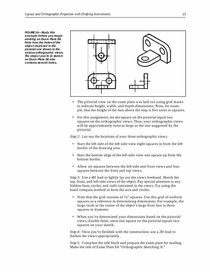
• The pictorial view on the exam plate was laid out using grid marksto indicate height, width, and depth dimensions. Note, for exam-ple, that the height of the face above the step is five units or squares.
• For this assignment, let one square on the pictorial equal twosquares on the orthographic views. Thus, your orthographic viewswill be approximately twice as large as the size suggested by the pictorial.
Step 2: Lay out the locations of your three orthographic views.
• Start the left side of the left-side view eight squares in from the leftborder of the drawing area.
• Start the bottom edge of the left-side view one square up from thebottom border.
• Allow six squares between the left-side and front views and foursquares between the front and top views.
Step 3: Use a 4H lead to lightly lay out the views freehand. Sketch thetop, front, and left-side views of the object. Pay special attention to anyhidden lines, circles, and radii contained in the views. Try using thehand-compass method to form the arcs and circles.
• Note that the grid consists of 1⁄4′′ squares. Use this grid of uniformsquares as a reference in determining dimensions. For example, thelarge circle in the center of the object’s large front face is threesquares in diameter.
• When you’ve determined your dimensions based on the pictorialviews, double them, since one square on the pictorial equals twosquares on your sketch.
Step 4: Once you’re finished with the construction, use a 2H lead todarken the views appropriately.
Step 5: Complete the title block and prepare the exam plate for mailing.Make the title of Exam Plate E4 “Orthographic Sketching A.”
FIGURE 14—Study thisexample before you beginworking on Exam Plate E4.Note how the holes of theobject depicted in thepictorial are shown in thevarious orthographic views.The object you’re to sketchon Exam Plate E4 alsocontains several holes.
Layout and Orthographic Projection with Drafting Instruments 23

Using Dividers to Complete Orthographic Views
Now you’ll learn some techniques for completing orthographic projec-tions, including how to add a missing third view when no pictorial infor-mation is given. Once again, you’ll progress one step at a time. You’lllearn that your dividers can be valuable for transferring dimensionswhen completing orthographic views.
Exam Plate E5
You’ll be drawing a different type of object now than you’ve been work-ing with previously. The object in this drafting assignment is the tubingclamp shown in Figure 15. Such a clamp would be formed from a flatpiece of steel sheet stock. It’s a hardware item that might be drawn, forexample, by an aerospace drafter working in an aeronautical firm. Brack-ets like this one, plus thinner parts made from sheet metal, are frequentlyused in the construction of rockets and aircraft.
Examine the pictorial drawing of the clamp shown in Figure 16. OnExam Plate E5, you’re to draw to full scale the top, front, and right-sideviews of the hydraulic tubing clamp. Place no dimensions on your fin-ished drawing.
Figure 17 shows the step-by-step procedure for drawing the ortho-graphic views of the tubing clamp. Refer to Figure 17 as you completeExam Plate E5.
Step 1: Set up the layout of your views on Exam Plate E5.
• Affix Exam Plate E5 to your drafting board. Position the plate sothat the title block is at the bottom.
• Draw a horizontal line and two vertical lines through points a andb as shown in Figure 17, block 1. Use a 4H lead for all constructionlines.
FIGURE 15—A hydraulictubing clamp, like the oneshown here, may bemounted on the bulkhead ofan aircraft fuselage.
24 Layout and Orthographic Projection with Drafting Instruments

Step 2: Refer to Figure 17, block 2 as you locate and draw very light hori-zontal lines to outline your three views.
• From Figure 16, you can see that the overall width of the clamp is4′′, its overall height is 11⁄2′′ (7⁄8′′ + 5⁄8′′), and its overall depth is13⁄8′′. Your top and front views show the height, width, and depthof the clamp. Your top view should thus be 4′′ by 13⁄8′′, and yourfront view should be 4′′ by 11⁄2′′.
• Locate and draw very light horizontal lines through points c, d,and e as shown in Figure 17, block 2.
• On your sheet, locate and draw a vertical line through point d′. Useyour dividers to transfer the depth dimension of your top view tothe side view, and locate point e′. Draw a vertical line through thispoint.
• You now have the rough outlines of the top, front, and right-sideviews located on your plate. In Figure 17, block 2, the three viewsare labeled T.V., F.V., and S.V. Note that the side view has the samedepth as the top view and is the same height as the front view.
FIGURE 16—Here is a pictorial drawing of the hydraulic tubing clamp. Note the dimensions given.
Layout and Orthographic Projection with Drafting Instruments 25

FIGURE 17—The step-by-step procedure in drawing the three views of the tubing clamp is illustrated here.
26 Layout and Orthographic Projection with Drafting Instruments

Step 3: With the outlines of the top, front, and side views located onyour plate, you can now start filling in the details of these views.
• While referring to Figure 16 and to Figure 17, block 3, locate lines 1,2, 3, 4, and 5 in your front view. Note that lines 2 and 5 serve as thecenterlines for drawing the 11⁄16′′ and 7⁄8′′ arcs.
• With your compass, draw the two arcs as shown in Figure 17, block3.
• Whenever a line in Figure 17 shows heavy and wide, it’s an indica-tion to you that it can be finished as a visible line. Remember to usea 2H lead in the compass.
Step 4: Refer to Figure 17, block 4 as you continue adding detail to yourdrawing.
• Project across to the side view and darken lines 6, 7, 8, and 9.
• Project from the front view to the top view as shown and constructlines 10, 11, 12, and 13.
• With your circle template, draw the two 1⁄4′′ arcs (1⁄2′′ diameter onyour template).
• The radii for the two larger arcs can be calculated. They’ll beequivalent to the size of the smaller arcs plus the thickness of thematerial (1⁄4′′ + 3⁄16′′), which will equal 7⁄16′′R. Use the 7⁄8′′ diameterhole on your circle template to create these arcs.
• In the top view, darken the four lines that you obtained by projection.
Step 5: Refer to Figure 17, block 5 to complete the details in your threeviews.
• In the top view, construct centerlines 14, 15, and 16 for the 5⁄16′′ diameter holes.
• With your dividers, transfer centerline 16 to the side view.
• Project centerlines 14 and 15 down to the front view.
• Darken the two 5⁄16′′ diameter holes. With your dividers, transferthe radius of each hole to the side view and make a mark on bothsides of centerline 16. Place a hidden line at each of these twopoints. The two hidden lines in the side view are the surface limitsof the two coinciding holes.
• From the top view, project the surface limits of the two holes downto the front view and place hidden lines at these points.
• With your circle template, draw the 1⁄4′′R arcs at each corner of thetop view.
Layout and Orthographic Projection with Drafting Instruments 27

Step 6: Prepare your exam plate for mailing.
• Darken the balance of the lines as shown in Figure 17, block 6.Check to ensure that all lines have been appropriately darkened—hidden lines, visible lines, and centerlines. The drawing part of theplate is now complete.
• Complete the title block. The title of Exam Plate E5 is “HydraulicTubing Clamp.”
Discussion of Exam Plate E5
In this assignment, you’ve completed a three-view orthographic drawingof the hydraulic tubing clamp. You were given the step-by-step proce-dure to be followed, and your completed drawing should be correct. Be-fore reading further in your study unit, reconsider your completeddrawing and the pictorial view in Figure 16. Try to understand the rea-sons for making the drawing as you did. The primary reason for makinga three-view drawing of the clamp was to describe its shape.
Use a piece of scratch paper to cover your side view. Look at your topand front views. These two views describe the clamp except for the rightside of the clamp. By reading the top and front views alone, you can’t tell theshape of the clamp’s right side.
Uncover your side view and cover the top view. When looking at just thetop and side views, you can’t tell anything about how the clamp is to be bent.
You should now realize that the three views of the clamp are necessaryto fully describe its shape. The shape of the object can’t be determined byreading any one or even any two of the views; the three views must be readtogether.
Before starting on your next drawing, restudy this entire assignment.Make sure you could solve this type of drafting problem without refer-ring to the step-by-step process. Make a freehand, three-view sketch ofthe clamp while referring to Figure 16 only, and then check your sketchusing Figure 17, block 6.
Using the 45° Miter Line to Complete Orthographic Views
In completing your last drawing, you used dividers to transfer depth di-mensions from the top view to the side view. You also previously usedthe drafting scale to lay out a depth dimension in the side view. Now,you’ll learn yet another method of transferring depth dimensions—you’ll learn how to use the 45° miter line.
Preparing to Draw
Keep your work clean. Before you start working on Exam Plate E6, in-spect the drafting instruments and supplies that you’ve been using. Layout your equipment and sharpen your leads. Clean your drafting equip-ment and the surface of your drafting board. Remember, if you’re to end
28 Layout and Orthographic Projection with Drafting Instruments

up with a clean drawing, you must keep all your equipment clean. Getinto the habit of periodically inspecting and cleaning your equipmentand work area. Dirt on your equipment will end up on your drawing.Once it’s completed, a drawing is hard to clean without erasing lines.
How the 45° miter line is used. Figure 18 shows how a 45° miter line isused to transfer depth dimensions from a top view to a right-side view.Point 0 is where two projection lines meet. One line is projected from thebottom edge of the top view; the other line is projected up from the leftedge of the side view. From point 0, you would draw the miter line witha 45° triangle. Transferring the depth dimensions is then done by project-ing first horizontally to the 45° line and then down vertically to locate thecorresponding edge or surface on the right-side view.
Exam Plate E6
The object for this drafting assignment is a heavy-gage piece of sheet met-al used as a bracket in an airplane (Figure 19). Step-by-step procedureswill again guide you through the procedure for completing the three or-thographic views. On Exam Plate E6, you’re to draw to full scale the top,front, and right-side views of the sheet metal bracket. Don’t place dimen-sions on your finished drawing.
FIGURE 18—The 45° miter linecan be used as shown hereto transfer dimensions fromone view to another.
Layout and Orthographic Projection with Drafting Instruments 29

Figure 20 shows the step-by-step procedure for drawing the ortho-graphic views of the metal bracket. Refer to Figure 20 as you completeExam Plate E6.
Step 1: Set up the layout of your views on Exam Plate E6.
• Tape Exam Plate E6 to your drafting board with the title block atthe bottom.
• Refer to Figure 20, block 1. Using the dimensions given, constructthe vertical lines marked a, b, and c and the horizontal linesmarked d, e, f, and g.
• At point o, where lines c and f intersect, construct a 45° miter lineuntil it intersects horizontal line g at point h.
• Draw a vertical line from point h until it intersects line d at point j.Do you see how the miter line transferred a dimension between thetop and right-side views? The distance from line c to line j is equalto the 3′′ distance from line f to line g. In this case, the transferreddimension is the 3′′ depth of the object. In your last drawing, thedepth dimension for the hydraulic tubing clamp was transferred using dividers. As you complete the details in the top view of thesheet metal bracket, you’ll find that the depth dimensions can all betransferred to the right-side view using the 45° miter line.
Step 2: Refer to Figure 20, block 2. Using the dimensions given in Figure19, construct lines 1 through 5 and darken them with your 2H lead.
FIGURE 19—Refer to thispictorial of an aircraft sheetmetal bracket as you workon Exam Plate E6. Use thegiven dimensions toconstruct the orthographicviews, but don’t put anydimensions on your finisheddrawing.
30 Layout and Orthographic Projection with Drafting Instruments

FIGURE 20—The step-by-step procedure in drawing the three views of the metal bracket is illustrated here.
Layout and Orthographic Projection with Drafting Instruments 31

Step 3: Refer to Figure 20, block 3. Using the given dimensions, constructlines 6, 7, and 8 in the front view and darken all lines from 6 through 12.
Step 4: Refer to Figure 20, block 4. Construct lines 14 and 17 in the right-side view by projecting through the 45°? Construct line 15 by projectingdirectly from the front view as shown. Before darkening lines 13 through17, draw the arc for the 1⁄8′′ radius. Also draw the arc for the other radiuswhich is tangent to lines 13 and 16. Since the thickness of the material is1⁄8′′, this latter radius is 1⁄4′′ (1⁄8′′ + 1⁄8′′). Use the 1⁄2′′ diameter circle on yourtemplate. Darken both radii, then darken lines 13 through 17.
Step 5: Refer to Figure 20, block 5 as you draw the 3⁄4′′ diameter holes.Create the centerlines and hidden lines for these holes in the front view bydirect projection as shown. Create these same lines in the right-side view using the 45° miter line. Darken and widen the lines appropriately, usinga 2H lead for visible lines and a 4H lead for hidden lines and centerlines.
Step 6: Refer to Figure 20, block 6. Draw the 1⁄4′′R slots in the front viewusing the given dimensions. Then, project directly to the top and right-sideviews as shown. Darken in these lines as necessary. Note the enlargedview of the slot in the upper right-hand corner: draw the arcs for the 1⁄4′′radii; then draw the lines that connect them.
Step 7: Prepare your exam plate for mailing.
• Your completed drawing should look similar to what’s shown inFigure 21. Check all your lines for the proper quality. Your center-lines should appear as shown. Remember, centerlines extend onlyabout 1⁄4′′ from the edge of a circle or other visible line.
• Make the title of this plate “Aircraft Sheet Metal Bracket.”
FIGURE 21—This is how your orthographic views of the sheet metal bracket should appear on Exam Plate E6.
32 Layout and Orthographic Projection with Drafting Instruments

Now, take a few moments to review what you’ve learned so far aboutmaking orthographic projections by completing Learning Check 2.
Learning Check 2Questions 1–10: Indicate whether each of the following statements isTrue or False.
_____ 1. A drawing instrument such as a compass or template is neces-sary to sketch an arc or circle.
_____ 2. In sketching circles, the circumference should be sketched first, then the centerlines.
_____ 3. In sketching, the overall dimensions should be laid out before sketching the details.
_____ 4. Sketches usually take longer to finish than do instrument drawings.
_____ 5. The drafter and engineer use sketches to quickly express, explain, and record ideas, butoccasionally a sketch is also used as a temporary shop drawing.
_____ 6. In orthographic projection, one view should be completely drawn before starting another.
_____ 7. Small circles can be drawn more easily with the compass than with a circle template.
_____ 8. Normally, you would select the right of the front view as your orthographic side view;however, it’s sometimes better to use the left of the front view instead.
_____ 9. In making an orthographic projection, you may use dimensions measured directly froma pictorial if that pictorial is drawn to scale.
_____ 10. In an orthographic view, the surface limits of a cylinder’s interior may appear asstraight, dashed lines.
(Continued)
Layout and Orthographic Projection with Drafting Instruments 33

Learning Check 2Questions 11–19: Refer to the pictorial drawing shown in Figure A, andselect the one lettered choice that best answers each question. Imaginethat you’re about to draw the three regular orthographic views of the ob-ject featured in the full-size pictorial drawing. The grid superimposedon the pictorial consists of 1⁄4′′ squares. The object is thus 1′′ deep by11⁄4′′ wide by 13⁄4′′ high.
11. The two small holes would show as circles in the
a. front view only. c. right-side and top view.b. top view only. d. three orthographic views.
12. In the right-side view, the interior of the large hole would be indicated using
a. a circle. c. the letter R.b. hidden lines. d. the letter D.
13. The two small arcs at the corners can be seen as arcs only in the
a. top and front views. c. front view.b. top view. d. right-side and top views.
14. The arc forming the object’s top edge would appear as a semicircle only in the
a. top and front views. c. front view.b. top view. d. right-side and top views.
15. Which of the following views would show the semicircle as a straight line rather than as an arc?
a. The top and right-side views c. The front and top viewsb. The front and right-side views d. All three orthographic views
(Continued)
FIGURE A—You shouldrecognize this pictorial viewfrom an earlier sketchingassignment. Now, assumethat you need to draw thetop, front, and right-sideviews and that you plan touse a circle template. Withthat assumption in mind,answer questions 11 through19.
34 Layout and Orthographic Projection with Drafting Instruments

Learning Check 216. To draw the semicircle, you would select a template circle with a
diameter listed as
a. 1⁄4′′. c. 3⁄4′′.b. 1⁄2′′. d. 11⁄4′′.
17. To draw the large hole, you would select a template circle with a diameter listed as
a. 1⁄4′′. c. 3⁄4′′.b. 1⁄2′′. d. 11⁄4′′.
18. The circle diameter for the small holes is
a. 1⁄4′′. c. 3⁄4′′.b. 1⁄2′′. d. 11⁄4′′.
19. The circle diameter for the two small radii is
a. 1⁄4′′. c. 3⁄4′′.b. 1⁄2′′. d. 11⁄4′′.
Question 20: In Figure B, several pictorial drawings are shown shuffled above their corre-sponding orthographic views. Your first task in answering this question is to match each lettered pictorial with its corresponding orthographic projection. Do so by writing the appro-priate letters in the spaces provided. Then, complete the orthographic views by supplying the missing hidden lines. Hidden lines are the only lines that are missing. Be sure to followthe established conventions in drawing these lines.
(Continued)
Layout and Orthographic Projection with Drafting Instruments 35

Learning Check 2
Check your answers with those on pages 51–52.
FIGURE B—Fill in each blank with the appropriate letter. Then, supply the hidden lines that are missing in the orthographic views.
36 Layout and Orthographic Projection with Drafting Instruments

MASTERING THE ORTHOGRAPHIC VIEWS
A New Slant on Orthographic Projection
Previously, you’ve been drawing objects with surfaces that were repre-sented in their true size and shape in at least one orthographic view. Ineach assignment, every surface was either perpendicular or parallel toyour line of sight in at least one of the orthographic views. For a changeof pace, look at the object pictured in Figure 22. It’s a simple block, butone corner is cut away at an angle, leaving a slanting surface. Do you seethat none of the three orthographic views show the slanting surface in itstrue size and shape? The surface is foreshortened in all three views.Now, let’s turn our attention to learning how to complete the ortho-graphic views of an object that has such a slanting surface.
Exam Plate E7
In this drafting assignment, you’re to sketch the top, front, and right-sideviews of the object represented by the pictorial view in Figure 23. Makeyour sketch full size; that is, on your exam plate, let each 1⁄4′′ squareequal 1⁄4′′ of the object’s actual size.
Locate the three views on your exam plate as indicated in Figure 24.Then, starting from the rough layout suggested in Figure 24, draw thetop, front, and right-side views of the object on Exam Plate E7. Finally,complete the title block. The title of Exam Plate E7 is “OrthographicSketching B.”
FIGURE 22—The pictorial viewin this drawing shows aslanting surface labeled D.Surface D isn’t parallel to anyregular plane of projection.Note also how the line of siteassociated with eachorthographic view fails tomeet surface D at a rightangle. Thus, none of thethree regular orthographicviews can show this slantingsurface in its true size andshape.
Layout and Orthographic Projection with Drafting Instruments 37

FIGURE 23—Refer to thispictorial as you construct thethree orthographic views.
FIGURE 24—Position the rough outlines of your three views as indicated here.
38 Layout and Orthographic Projection with Drafting Instruments

Discussion of Exam Plate E7
Refer to the pictorial drawing in Figure 23 and note the set of pointsmarked A, B, and C and the set marked 1, 2, 3, 4, and 5. Label thesepoints on the top, front, and right-side views that you’ve sketched onyour exam plate. If you’ve sketched the views correctly, all of thesepoints should appear on your top view and on your right-side view.Check each of your three orthographic views to make sure the letters andnumbers are located as indicated here.
Top view.
• Letter B, right side, 2 squares from back
• Letter C, front right corner
• Letter A, front face, 6 squares from right side. (A and B should beconnected.)
• Numbers 1 and 4, left side, 4 squares from back
• Numbers 2 and 3, front face, 6 squares from left side
• Number 5, front left corner. (Points 1, 2, 3, and 4 should be connected.)
Front view.
• Letter A, top face, 6 squares from right side
• Letter B, top right corner
• Letter C, right face, 2 squares from bottom. (A and C should be connected.)
• Number 1, top left corner
• Number 2, top face, 6 squares from left side
• Number 3, 4 squares from bottom, 6 squares from left side
• Numbers 4 and 5, left face, 4 squares from bottom. (Points 2 and 3should be connected and points 4, 5, and 3 should be connected.)
Right-side view.
• Letter A, top left corner
• Letter B, top face, 2 squares from back (right side of side view)
• Letter C, front face (left edge of side view), 2 squares from bottom.(Points B and C should be connected.)
• Number 1, top face, 4 squares from back
• Number 2, top left corner
• Numbers 3 and 5, front face (left edge), 4 squares from bottom
• Number 4, in the middle of the right-side view
Layout and Orthographic Projection with Drafting Instruments 39

The Oblique Surface
The object shown in Figure 25 has one corner cut away at an angle. Youlearned previously that angular surfaces such as this won’t show theirtrue size and shape in any of the orthographic views. Top, front, and sideviews all show surface A—but the surface is foreshortened in each case.The surface is inclined relative to all three planes of projection: the hori-zontal plane, the frontal plane, and the side (or profile) plane. Such a sur-face is considered an oblique surface. An oblique surface is slanted, orskewed, so that it’s neither parallel nor perpendicular to the planes ofprojection.
Look again at Figure 25. As previously discussed, surface A is an obliquesurface, inclined to the planes of projection. Surface B, on the other hand,is the type of surface to which you’re accustomed. It’s parallel to the fron-tal plane and perpendicular to both the horizontal plane and the profileplane. These planes, of course, are the surfaces of the imaginary glass boxused in orthographic projection. Now, consider surface C. Relative to theobject’s other surfaces, it’s slanted at an angle, but is surface C oblique inregards to all the planes of projection? It’s inclined to both the horizontaland frontal planes, but look at the right-side view and then again at thepictorial. The edge of surface A is revealed in its true size as a line in theright-side view. Surface A, in fact, is perpendicular to the profile plane.Look at surface A again. Do you see that surface A is inclined to all of theplanes of projection? If you don’t thoroughly understand why surface Ais not oblique in regards to the profile plane, read this paragraph againand re-examine Figure 25.
FIGURE 25—As you already know, the only way to represent an oblique surface in the regular orthographic views isby locating each corner of the surface and then connecting the corners with lines. An oblique surface, such assurface A shown here, will be foreshortened in the orthographic views.
40 Layout and Orthographic Projection with Drafting Instruments

The Importance of Planning Your Views
Whenever you make a sketch or drawing that contains several views onone sheet of paper, you’ll need to carefully plan the spacing of yourviews. Before working on the details of any one view, you must ensurethat all the views will fit on your plate properly—with good marginsaround each view. Planning like this can be especially important whenyou’re dealing with compact drafting plates, such as the ones you’reworking on in these drafting assignments. Regardless of the size of yourdrawing space, however, the method of working out the positions foryour views is the same. Let’s practice positioning orthographic views us-ing Figure 26 as an example.
Let’s assume that you want to space out three orthographic views for theobject shown in Figure 26A. The object has the following overall dimen-sions: 51⁄4′′ width, 13⁄4′′ depth, and 3′′ height. Let’s also assume thatyou’ll be drawing within a 101⁄2′′ by 7′′ space as shown in Figure 26B,block 1.
To accommodate your front and side views, you’ll need 7′′ across thewidth of the drawing space (51⁄4′′ for the front view and 13⁄4′′ for theright-side view). With a total work space width of 101⁄2′′, you have 31⁄2′′of space to divide up for margins. You’ll want a margin at the right, atthe left, and between the views.
Initially, plan on leaving outside margins of about 1′′. Regardless of whatsize you actually settle on, however, the left and right outside marginsshould be equal. In this case, you can allow 11⁄4′′ as left and right outsidemargins, leaving you with a 1′′ gap between the front and side views.Figure 26B, block 2 shows your planned layout so far.
Next, consider the vertical dimension of the drawing space. From top tobottom, the front view measures 3′′. Add to this the depth of the topview (13⁄4′′), and you’ll find you need a total of 43⁄4′′ to accommodate thedrawing. You have a total of 7′′ to work with from the top to the bottomof your drawing space. Thus, you have an excess of 21⁄4′′ to split up asmargins above, below, and between the top and front views. If you leavea 3⁄4′′ space between the two views, you’ll have 11⁄2′′ of space left over.You could divide the extra space evenly (3⁄4′′ and 3⁄4′′) to form the topand bottom margins, but you’ll obtain a better appearance in your draw-ing and better visual balance if you leave a little less on top than you doon the bottom. Figure 26B, block 3 shows how the top and bottom mar-gins may be adjusted for visual appeal. In this case, you can leave a mar-gin of 5⁄8′′ at the top and a margin of 7⁄8′′ at the bottom. Figure 26B, block4 shows how the views may be arranged on the final drawing. With well-planned margins around the views, the drawing has an overall appear-ance of neatness and professionalism.
Layout and Orthographic Projection with Drafting Instruments 41

FIGURE 26—How to position multiple views on a single drafting plate is illustrated here.
42 Layout and Orthographic Projection with Drafting Instruments

Exam Plates E8 and E9
Look now at Exam Plates E8 and E9, and try to visualize the object de-picted by the pictorial view in the upper right-hand corner of each plate.Your drafting assignment is to sketch the top, front, and right-side viewsof these objects.
Note that both exam plates feature a grid of squares for estimating scale.On Exam Plate E8, make your sketch full scale; that is, let each squareunit of the pictorial correspond to one square unit on your sketch. OnExam Plate E9, make your sketch double scale; that is, let each squareunit of the pictorial correspond to two square units on your sketch.
Step 1: Set up the layout of your views on Exam Plates E8 and E9.
• Space your orthographic views appropriately.
• Remember to use a 4H lead for the initial layout, then go over yourlines with a round-pointed 2H lead.
Step 2: Sketch the regular orthographic views on each plate.
• Use the proper sketching techniques. Make bold, continuousstrokes as you darken the lines.
• Complete the title blocks. The title of Exam Plate E8 is “Ortho-graphic Sketching C.” The title of Exam Plate E9 is “OrthographicSketching D.”
Practice in Visualizing the Third View
In all of the orthographic projection problems thus far, you’ve had a pictorial view to aid you in laying out the orthographic views. Tostrengthen your ability in reading orthographic views, you’ll now dosome drafting exercises without the aid of a pictorial. Because some speci-fications or directions have to be provided, you’ll be given two views ofan object and will be asked to complete the third view based on the infor-mation contained in the other two. Some surfaces depicted in the viewsare inclined; others are more conventional. In each case, there’s sufficientinformation in the given views to enable you to complete the third view.Exercises like this are always challenging and interesting; try your bestand you’ll benefit the most from them. If you continue practicing withthese kinds of problems, you’ll soon master orthographic reading.
Exam Plate E10
Before you complete this drafting assignment, you should review anyprevious instruction on orthographic projection. While you’re already fa-miliar with many of the basic ideas, including the “glass box” concept,you’ll likely benefit from such a review.
Exam Plate E10 contains four problems in orthographic reading. In eachproblem, you’re given a complete top and side view of an object. You’reto sketch, freehand, the front view of each of the objects.
Step 1: Examine the first orthographic problem presented in block 1 ofExam Plate E10. The top and right-side views of an object are shown in
Layout and Orthographic Projection with Drafting Instruments 43

this block. By “reading” the two views, you can form a mental picture ofthe shape of the object. After you’ve formed this picture in your mind,you’ll be able to sketch the missing front view.
• In the top view, one of the object’s surfaces is labeled A. Note thatface A is also marked in the side view. In the side view, face A ap-pears as a horizontal line, which is an edge view of the face. Be-cause face A appears as a horizontal line, the top of the object mustbe horizontal—that is, the top doesn’t slope. From the outline in thetop view, you also know that the object’s top surface, face A, has aU shape.
• Face D is also marked on the object. This face appears as a line inthe top view. This line is the edge view of face D. In the side view,face D appears again as a line, or edge. According to the top view,face D is three squares wide and is set back two squares from thefront of the object. The side view shows that face D extends fromthe top to the bottom of the object. In the side view, face D appearsas a hidden line, indicating that there’s something on the right sideof the object hiding face D when the object is viewed from the side.By looking at the side view, you can also confirm that face D is twosquares back from the front, something you already knew from ex-amining the top view.
• By now, you can visualize face D as the back face of a slot that runsdown through the object from top to bottom. Edge views of theslot’s three sides can be seen in the top view.
• The object depicted in these views is a rectangular block that has aslot cut out of its front portion. The block is seven squares wide,four squares deep, and four squares high. The slot is three squareswide, two squares deep, and is as high as the object itself (foursquares).
Step 2: Complete the front view of the object in block 1 of Exam PlateE10. Sketch your lines lightly with your 4H lead until you have a definiteoutline. Then, darken with your 2H lead.
Step 3: Examine the second orthographic problem presented in block 2of Exam Plate E10. The object shown in block 2 is similar to the objectshown in block 1, except there’s one additional slot.
• When you read the top and side views together, you’ll see thatfaces A and C are on the top of the object. Face B is in the middle—between faces A and C—and is at the back of the object. By lookingat the side view, you can see that face B is only two squares upfrom the bottom of the object. Thus, even the edge view of face B ishidden when the object is viewed from the side. The outline of faceB is formed with visible lines only when the object is viewed fromthe top. Face D, as indicated in the top view, is the back of the slotcut into the front of the object. By looking at the side view, you cansee that face D is two squares high.
• The object shown in block 2 of Exam Plate E10 is a rectangularblock with two slots cut in the middle of its front face. One slot iscut from top to bottom, and the other is cut from front to back.
44 Layout and Orthographic Projection with Drafting Instruments

Step 4: Sketch the front view of the object in block 2 of Exam Plate E10.
Step 5: Examine the third orthographic problem presented in block 3 ofExam Plate E10. Again, this object is similar to the one you’ve worked onpreviously. The difference here is that one of the object’s top faces is nolonger horizontal.
• Line X in the side view represents the edge view of a sloping face.You must read the orthographic views to discover which surface—face A, face B, or face C—is the sloping surface indicated by line X.The top view shows face B going only partway across the objectfrom back to front. Line X, however, indicates that the sloping faceextends all the way to the front. Therefore, face B can’t be the slop-ing face. (Remember that—in the orthographic projection—theback of the object is the far right edge in the right-side view and theupper edge in the top view.) If line X isn’t the edge view of face B, itmust be the edge view of either face A or face C. Face C is on theright side of the object. Because face C is on the right of the object,it’s fully visible in the right-side view. If face C were the slopingface, its edge would thus be indicated by a visible line in the sideview. Line X, therefore, must represent the edge of face A. Face A,as seen from the top, is on the left side of the object. An edge of thatface is properly represented by a hidden line in the right-side view.
• The front view of face A will be foreshortened, as were the slopingfaces on previous objects you’ve drawn.
Step 6: Complete the front view of the object in block 3 of Exam PlateE10.
Step 7: Examine the fourth orthographic problem presented in block 4 ofExam Plate E10.
• When you’re reading the top view, imagine that you’re above theobject, looking straight down at the object’s top. When you’re inthis position, you can tell how wide the object is from right to leftand how deep the object is from front to back. However, you can’ttell how high the object is. Try imagining that the top view is raisedsomewhat off the paper so that you can visualize the object as alsohaving height. You need to glance at the side view to determine theobject’s actual height. Look at the top view in block 4 of Exam PlateE10. You see that the object is seven squares wide and four squaresdeep overall. You can also see that a slot is cut out of the front ofthe object. This slot is three squares wide and two squares deep.The outlines of face A and face C are also displayed in the top view.You know that these two surfaces aren’t at the same level becausethere’s a line between them. Face C is rectangular in shape, andface A has an L shape. By reading only the top view, you’ve formeda mental picture of most of the object.
• To complete your mental picture of the object, you need to read theside view. By reading the side view, you can see that face C is ontop and face A is two squares down from the top. A side view re-veals the height and depth of the object. When you examine a sideview, imagine that it extends into the paper so you can correctlyvisualize the object as also having width.
Layout and Orthographic Projection with Drafting Instruments 45

• By now you should have a good mental picture of the object repre-sented in block 4 of Exam Plate E10. When you’re ready to drawthe front view, imagine that you’re standing in front of the object,looking straight at the object’s front. When you sketch the frontview, look at the top view and project downward to obtain thewidth dimensions of the front view. Project across from the sideview to obtain the height dimensions.
Step 8: Sketch the front view of the object in block 4 of Exam Plate E10.
Step 9: Complete the title block. The title of Exam Plate E10 is “Ortho-graphic Sketching E.”
Discussion of Exam Plate E10
Earlier, you drew the top, front, and side views of objects that had beendepicted in pictorial views. Here, you had to form your own mental pic-ture of an object by “reading” the given orthographic views. When youdrew the front view of an object previously, you had looked at the pic-ture of the object from the front and drew that view of the object. Beforeyou were able to draw the front views for Exam Plate E10, you had toconstruct the objects in your mind.
Refer to block 1 of your completed exam plate, and reconstruct the objectone more time.
Look at the top view, then glance down at your front view. The top viewis the view you would see when looking down on the top of the same ob-ject depicted in your front view.
Look at the front view in block 1, then glance up at the top view. Thefront view is the view you would see when looking at the front of thesame object depicted in the top view.
Look again at your front view, then glance to the right at your side view.The front view is the view you would see of the same object to the leftside of the right-side view. That is, the left side of the right-side view isactually the front of the object.
From the side view, glance at the front view. The side view is the viewyou would see when looking at the right side of the object’s front.
Look at the side view, then glance at the top view. The side view is thesame view of the object that you would see if you looked to the rightfrom the top-view perspective. However, on the drafting plate, the sideview is “rotated” and brought down alongside the front view.
In your mind, reconstruct the object represented by the orthographicviews in block 2. As you did with block 1, read the orthographic viewsso that they describe the object. Read the views also in blocks 3 and 4. Bypracticing in this way, you’ll be able to form a clear mental picture of anyobject after only a few moments of studying the object’s orthographicviews.
Now, take a few moments to review what you’ve learned about readingorthographic views by completing Learning Check 3.
46 Layout and Orthographic Projection with Drafting Instruments

Learning Check 3Questions 1–10: Refer to the pictorial view shown here. Select the onelettered choice that best answers each question.
1. The true size and shape of the sloping face A-B-C would be revealed in
a. the top view only.b. only the top and front views.c. the top, front, and right-side views.d. none of the three regular orthographic views.
2. The true size and shape of face 3-4-5 would be revealed in
a. the top view only.b. only the top and front views.c. the top, front, and right-side views.d. none of the three regular orthographic views.
(Continued)
Layout and Orthographic Projection with Drafting Instruments 47
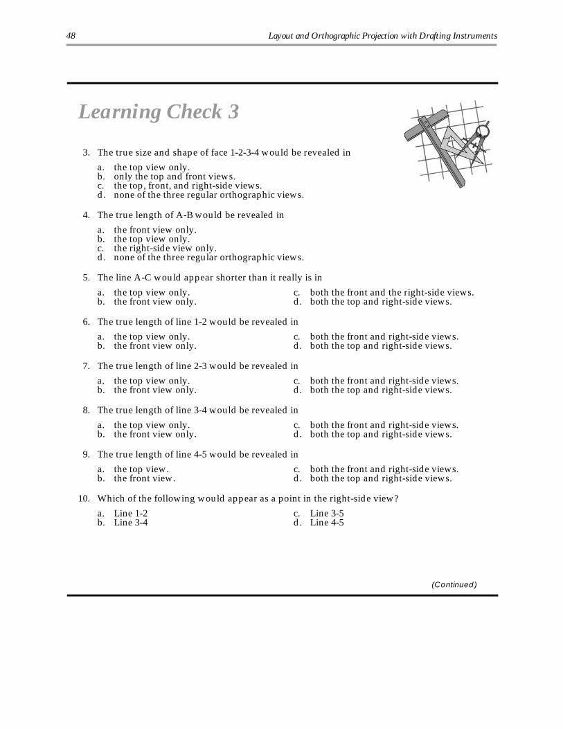
Learning Check 3
3. The true size and shape of face 1-2-3-4 would be revealed in
a. the top view only.b. only the top and front views.c. the top, front, and right-side views.d. none of the three regular orthographic views.
4. The true length of A-B would be revealed in
a. the front view only.b. the top view only.c. the right-side view only.d. none of the three regular orthographic views.
5. The line A-C would appear shorter than it really is in
a. the top view only. c. both the front and the right-side views.b. the front view only. d. both the top and right-side views.
6. The true length of line 1-2 would be revealed in
a. the top view only. c. both the front and right-side views.b. the front view only. d. both the top and right-side views.
7. The true length of line 2-3 would be revealed in
a. the top view only. c. both the front and right-side views.b. the front view only. d. both the top and right-side views.
8. The true length of line 3-4 would be revealed in
a. the top view only. c. both the front and right-side views.b. the front view only. d. both the top and right-side views.
9. The true length of line 4-5 would be revealed in
a. the top view. c. both the front and right-side views.b. the front view. d. both the top and right-side views.
10. Which of the following would appear as a point in the right-side view?
a. Line 1-2 c. Line 3-5b. Line 3-4 d. Line 4-5
(Continued)
48 Layout and Orthographic Projection with Drafting Instruments

Learning Check 3Questions 11–20: Refer to the drawing shown here. Select the one let-tered choice that best answers each question.
11. Surface A is parallel to
a. the frontal plane. c. the horizontal plane.b. the profile plane. d. none of the regular orthographic planes.
12. Surface C is parallel to
a. the profile plane. c. the profile plane.b. the horizontal plane. d. none of the regular orthographic planes.
13. Surface B is perpendicular to
a. the profile plane. c. the frontal plane.b. the horizontal plane. d. none of the regular orthographic planes.
14. Relative to the planes of projection, surface B is most accurately called a/an
a. oblique surface. c. angular surface.b. horizontal surface. d. vertical surface.
(Continued)
Layout and Orthographic Projection with Drafting Instruments 49

Learning Check 3
15. Relative to the planes of projection, surface A is most accurately calleda/an
a. vertical surface.b. oblique surface.c. horizontal surface.d. perpendicular surface.
16. Surface D is perpendicular to the
a. frontal plane and surface B. c. horizontal plane and surface A.b. horizontal plane and surface F. d. frontal plane and surface C.
17. Surface F is parallel to
a. the horizontal plane. c. the frontal plane.b. surface C. d. surface E.
18. Surface E is perpendicular to
a. surface B. c. all the lettered surfaces except A and B.b. the frontal plane. d. surface A.
19. Surfaces A and B are
a. parallel to each other. c. both parallel to the profile plane.b. perpendicular to each other. d. both inclined to the frontal plane.
20. Only an edge of surface B is revealed in the
a. front view. c. top view.b. side view. d. pictorial view.
Check your answers with those on page 52.
50 Layout and Orthographic Projection with Drafting Instruments

1
1. Right
2. Wrong
3. Wrong
4. Right
5. Wrong
6. Right
7. visible
8. four
9. centerline
10. clean
11. False. If a hidden line won’t add clarity to adrawing or if it would cause confusion,you should not show it.
12. False. When hidden and visible lines coin-cide, the visible lines take precedence.
13. True
14. False. Maintaining uniformity is a goodway to ensure your drawings will be presentable.
15. False. The surfaces of an object are shownin a pictorial as they would appear if anobserver were looking at the object inthree-dimensional space. In addition, thepictorial in Figure 5A is drawn to halfscale.
16. True
2
1. False. Sketching is freehand drafting—drafting done without the use of such in-struments as templates and compasses.An arc or a circle can be sketched by us-ing, for example, the hand-compassmethod.
2. False. On a sketch, you would use the inter-secting centerlines to locate the center ofyour circle. Once you’ve established thecenter, you can then easily sketch the cir-cle’s circumference.
3. True
4. False. Because of the additional time re-quired to handle the instruments, draw-ing can often take longer than sketching.
5. True
6. False. With some sketches and drawings, itmay be faster and easier to develop allthe views at once by adding more andmore detail, in stages, to all the views.
7. False. The circle template is easier to usethan is the compass. Usually, the compasscomes in handy for drawing arcs and cir-cles of odd sizes that aren’t included onthe template.
8. True
9. True
10. True
11. b
12. b
13. b
14. c
15. a
16. d
Learning Check Answers
51

17. c
18. a
19. b
20. Compare your answer to the drawingshown here.
3
1. d
2. a
3. d
4. b
5. d
6. a
7. c
8. a
9. d
10. c
11. d
12. c
13. a
14. c
15. b
16. d
17. a
18. c
19. d
20. b
52 Learning Check Answers