style 3481, 3483 streammaster ii™ handwheel · pdf fileinstallation, operating, and...
TRANSCRIPT
124286
STYLE 3481, 3483 STREAMMASTER II™ HANDWHEEL MONITORINSTALLATION, OPERATING, AND MAINTENANCE INSTRUCTIONS
Thefollowingisintendedtoprovidethebasicinstructionsforinstallation,operationandmaintenance.Read andunderstandtheseoperatinginstructionsbeforeuse.

Page02
MechanicalSpecifications3481Parameter US Measure Metric Measure
FlowRate 2000GPM 7600LPM
MaxOperatingPressure
250PSI 17Bar
Mass 33.3Lbs 15.1kg
MechanicalSpecifications3483Parameter US Measure Metric Measure
FlowRate 1500GPM 5700LPM
MaxOperatingPressure
250PSI 17Bar
Mass 31Lbs 14.1kg
Tools Required•Wrenchforflangemountingbolts
Safety Symbols
Indicatesahazardoussituationwhich,ifnotavoided,WILLresultindeathorseriousinjury
Indicatesahazardoussituationwhich,ifnotavoided,COULDresultindeathorseriousinjury
Indicatesapotentiallyhazardoussituationwhich,ifnotavoided,mayresultinminorormoderateinjury
Addresspracticesnotrelatedtopersonalinjury
Product Warnings, Cautions and Notices
Chargetheunitslowly.Rapidchargingmaycauseapressuresurgethathasthepotentialtocauseaninjury, ordamagethemonitor.
Donotexceedthemaximumpressureorflowratingsofthemonitor.Exceedingtheseratingsmayleadtoan injuryormaycausedamagetothemonitor.
Donotinstallshutoffsontheoutletofthemonitor.Shutoffsincreasethepotentialforpressuresurges duetowaterhammer,whichhavethepotentialtocauseaninjuryordamagethemonitor.
Disconnectpoweranddisableflowbeforemaintenance.
KeepallpersonneloutoftheDangerZone,infrontoftheoutletofthemonitorwhenthewatersourceis attached.Dangerousflowvelocitiescancauseseriousinjury.
Notdesignedforexplosiveenvironments.
Useonlyforfirefightingbytrainedoperators.
Ensurethethreadonthenozzleswivelmatchesthethreadonthemonitoroutlet.Donotover-tightenthe nozzleontotheunit.
Insufficientstructuralsupportattheinletflangecanleadtofailure,whichhaspotentialtocauseaninjury.
Donotusemonitorornozzleasaforcibleentrytool.
Page03
EnsurethatthemonitorisreturnedtotheStowpositionafteruse.
Duringfreezingconditions,themonitormustbedrainedtopreventdamage.
Themonitor,nozzle,andfieldadjustablestopsaremadeforoptimal performance.Donotalterinanymanner.
ThemonitorwasdesignedforusewithAkronnozzles.Useofanyothernozzlescouldaffectthespeed oroperationoftheunitandshouldbetestedbeforebeingputintoservice.
Replacetheidentificationtagsiftheyshouldbecomewornordamaged.
Themonitorusescurrentlimitingforboththemonitorandnozzle.Useonlyappropriate AkronBrassCompanynozzles.
Notrecommendedforuseinsaltwaterapplications.
Forusewithwaterorstandardfirefightingfoamsonly.Afterusewithfoam,flushwithfreshwater.
Notrecommendedtomountontoaraisedflange.Thismaycausedamagetothemonitor’sflange whentighteningbolts.
Useanozzleofthesamematerialasthemonitortoeliminatetheeffectsofgalvaniccorrosion.
2-1/2
2-1/4
22-1/8
4-1/25-11/16
18-1/4
5-1/25-1/4
15-3/8
12-7/167-7/16
10-5/8
12-5/16
31/32
3-1/2" NH OUTLET
4", 150 LB FLANGE
5-3/16
5-11/16 3-3/4 7-27/64
18-1/4
5-17/64
11-5/8
21-5/16
2-1/2
2-1/4
15
10-19/32
31/32
2-1/2" NH OUTLET
3", 150 LB FLANGE
Page04
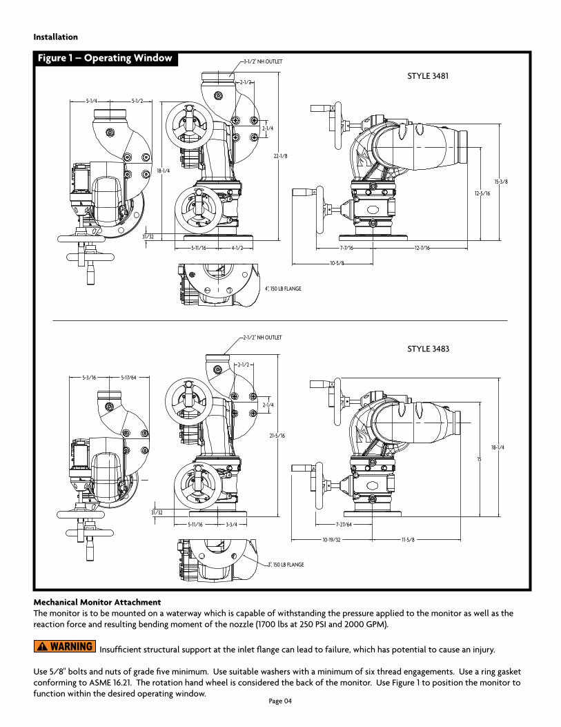
Figure 1 – Operating Window
Mechanical Monitor AttachmentThemonitoristobemountedonawaterwaywhichiscapableofwithstandingthepressureappliedtothemonitoraswellasthereactionforceandresultingbendingmomentofthenozzle(1700lbsat250PSIand2000GPM).
Insufficientstructuralsupportattheinletflangecanleadtofailure,whichhaspotentialtocauseaninjury.
Use5/8"boltsandnutsofgradefiveminimum.Usesuitablewasherswithaminimumofsixthreadengagements.UsearinggasketconformingtoASME16.21.Therotationhandwheelisconsideredthebackofthemonitor.UseFigure1topositionthemonitortofunctionwithinthedesiredoperatingwindow.
Installation
STYLE3481
STYLE3483
Page05
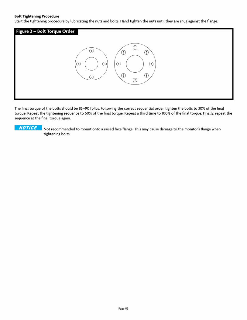
Bolt Tightening ProcedureStartthetighteningprocedurebylubricatingthenutsandbolts.Handtightenthenutsuntiltheyaresnugagainsttheflange.
Thefinaltorqueoftheboltsshouldbe85–90ft-lbs.Followingthecorrectsequentialorder,tightentheboltsto30%ofthefinaltorque.Repeatthetighteningsequenceto60%ofthefinaltorque.Repeatathirdtimeto100%ofthefinaltorque.Finally,repeatthesequenceatthefinaltorqueagain.
Notrecommendedtomountontoaraisedfaceflange.Thismaycausedamagetothemonitor’sflangewhen tighteningbolts.
Figure 2 – Bolt Torque Order
1
2
34
1
2
34
5
6
7
8
Page06
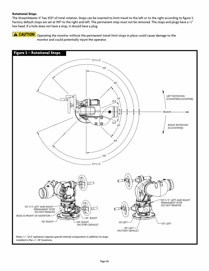
Rotational StopsTheStreamMasterII™has355ºoftotalrotation.Stopscanbeinsertedtolimittraveltotheleftortotherightaccordingtofigure3.Factorydefaultstopsaresetat90ºtotherightandleft.Thepermanentstopmustnotberemoved.Thestopsandplugshavea½”hexhead.Ifaholedoesnothaveastop,itshouldhaveaplug.
Operatingthemonitorwithoutthepermanenttravellimitstopsinplacecouldcausedamagetothe monitorandcouldpotentiallyinjuretheoperator.
Figure 3 – Rotational Stops
45°
90°
135°
177-1/2°
45°
90°
135°
177-1/2°
45° LEFT
90° LEFTFACTORY DEFAULT
135° LEFT
157-1/2° LEFT AND RIGHTPERMANENT STOPDO NOT REMOVE
45° RIGHT
90° RIGHTFACTORY DEFAULT
135° RIGHT
157-1/2° LEFT AND RIGHTPERMANENT STOPDO NOT REMOVE
BOSS IS FRONT OF MONITOR
FRONT
LEFT ROTATION(COUNTERCLOCKWISE)
RIGHT ROTATION(CLOCKWISE)
22.5°
22.5°
Note:+/-22.5°operationrequiresspecialinternalcomponentsinadditiontostopsinstalledinthe+/-45°locations.

Page07
Elevation StopsTheStreamMasterII™has90°oftravelabovehorizontaland45ºbelowhorizontal,whichislimitedbythepermanentstop.Thesestopsshouldnotberemoved.Stopscanbeinsertedtolimittravelaboveandbelowhorizontalaccordingtofigure4.Factorydefaultstopsaresetat45°abovehorizontaland45°belowhorizontal.Thestopsandplugshavea5/8"hexhead.Ifaholedoesnothaveastop,itshouldhaveaplug.
Operatingthemonitorwithoutthepermanenttravellimitstopsinplacecouldcausedamagetothemonitor andcouldpotentiallyinjuretheoperator.
Nozzle InstallationThenozzleshouldbethreadedontotheoutletofthemonitor.Verifythattheactuatororientationdoesnotinterferewiththemonitor.
Ensurethethreadonthenozzleswivelmatchesthethreadonthemonitoroutlet.Donotover-tightenthe nozzleontotheunit.
Useanozzleofthesamematerialasthemonitortoeliminatetheeffectsofgalvaniccorrosion.
Figure 4 – Elevation Stops
45°PT Z
90°PT Y
(FACTORY SET)
(PERMANENT STOP)
(PERMANENT STOP)
(PERMANENT STOP)
-20°PT B
-45°PT A
(PERMANENT STOP)
PT B
PT A
PT Y
PT Z

WARRANTY AND DISCLAIMER: We warrant Akron Brass products for a period of five (5) years after purchase against defects in materials or workmanship. Akron Brass will repair or replace product which fails to satisfy this warranty. Repair or replacement shall be at the discretion of Akron Brass. Products must be promptly returned to Akron Brass for warranty service.
We will not be responsible for: wear and tear; any improper installation, use, maintenance or storage; negligence of the owner or user; repair or modification after delivery; damage; failure to follow our instructions or recommendations; or anything else beyond our control. WE MAKE NO WARRANTIES, EXPRESS OR IMPLIED, OTHER THAN THOSE INCLUDED IN THIS WARRANTY STATEMENT, AND WE DISCLAIM ANY IMPLIED WARRANTY OF MERCHANTABILITY OR FITNESS FOR ANY PARTICULAR PURPOSE. Further, we will not be responsible for any consequential, incidental or indirect damages (including, but not limited to, any loss of profits) from any cause whatsoever. No person has authority to change this warranty.
ISO 9001 REGISTERED COMPANY
PHONE:330.264.5678or800.228.1161IFAX:330.264.2944or800.531.7335Iakronbrass.com
©AkronBrassCompany.2000Allrightsreserved.NoportionofthiscanbereproducedwithouttheexpresswrittenconsentofAkronBrassCompany.
REVISED:1/18
Maintenance Instructions •Themonitorshouldbekeptcleanandfreefromdirt. •Inspectfordamagedcomponentsandrepairorreplaceasneeded. •Themonitorshouldmovefreelyandsmoothlywithouthesitating. •Inspectmonitorforleaks.Replacesealsasneeded.UseParkerO-RinglubricantonO-Rings. •Greasefittingsareinstalledatwormgearandballbearingjoints.Ifmovementofthejointisnotsmooth,greaseuntilnormaloperationisrestored.Donotover-applygreaseusingagreasegun.Pressurewillbuildinthemonitorcavityandcouldcausedamagetothemonitor.Theelevationjointbearingsdonotrequiregrease.