submarine optical fiber cable: development and laying results
TRANSCRIPT

Submarine optical fiber cable: development andlaying results
Nobuya Kojima, Tetsuro Yabuta, Yukiyasu Negishi, Kazuo wabuchi, Osamu Kawata, Katsuya Yamashita,Yoshiaki Miyajima, and Nobuyuki Yoshizawa
This paper describes the structural design, trial production, and laying results for submarine optical fibercables that can be deployed in shallow seas between islands and/or channel crossings without repeaters.Structural design methods for the submarine optical fiber cable are proposed, which take into considerationsuppressing cable elongation under tension and excess loss under hydraulic pressure. This paper describesgood laying results for the cable using this structural design method. The average loss for single-mode fiberswas 0.72 dB/km, and the average loss for multimode fibers was 0.81 dB/km for a 10.2-km long cable operatedat 1.3-Am wavelength.
I. Introduction
The low loss characteristics of optical fibers can beused to advantage in submarine optical fiber cable.Therefore, submarine optical fiber cable developmenthas been vigorously pursued by several laboratories. 1 4
This paper describes the design, characteristics, andfield test results of a submarine optical fiber cable thatcan be used between islands and/or for channel crossingwithout repeaters. The target cable length for thissystem is 50 km without repeaters.
In the structural design, a torqueless armoringstructure was studied to decrease cable elongation undertension, since fiber breaking elongation is very small.A copper pipe is used to protect fibers from hydrauliclateral pressure during both laying and recovery. Thepipe design, considering irregularity distribution alongthe pipe length, is described.
A 10.2-km field test was accomplished using thesubmarine optical fiber cable designed in this way. Theaverage loss for single-mode fiber after laying with 0.72dB/km, and the average loss for multimode fiber was0.81 dB/km for 1.3-grm wavelength. These results meanthat low loss and high transmission capacity in a sub-marine cable can be obtained using optical fibers.
The authors are with Nippon Telegraph & Telephone PublicCorporation, Ibaraki Electrical Communication Laboratory, Tokai,Ibaraki, 319-11, Japan.
Received 26 June 1981.0003-6935/82/050815-07$01.00/0.© 1982 Optical Society of America.
11. Structural Design
A. Design ObjectivesThe design objectives for the submarine cable are
listed in Table I. The cable is to be used betweenislands and/or for channel crossings. The maximumwater depth is 1500 m in view of the service area in-volved. It is necessary to decrease fiber elongationduring laying and recovery because the breaking elon-gation is very small. Cable elongation for the armoredcable during laying and recovery is approximately de-scribed as5
SphIo -HE
(1)
where e = cable elongation, h = water depth, p = tensionmember density in water, S = coefficient connectedwith laying and recovery, = correct coefficient oftensile strength rigidity, and E = Young's modulus.Only armored submarine optical fiber cable is consid-ered in this paper because this cable is used for shallowseas, where cable is subject to trawling and fishingequipment damage.
Since cable elongation is not related to the cross-sectional area of the tension members as shown in Eq.(1), it is impossible to decrease cable elongation by in-creasing the tension member cross-sectional area. Thisis because the increase in tension member sectional areaalso increases the cable weight, and greater cable weightcauses larger cable elongation.
The correct coefficient of tensile strength f3, whichdepends on the tension member structure, indicatesthat the cable is easy to elongate when : is small. Forarmored cables, : is not more than 0.5-0.6.6 Themaximum value of3 = 0.5 is used as the design objectiveto decrease the cable elongation under tension.
1 March 1982 / Vol. 21, No. 5 / APPLIED OPTICS 815

Table I. Design Objectives
Item Objective
Tension >12 tonsFiber breaking elongation >0.5%Bending radius 75 cmWater depth <1500 m
Equation (1) shows that the cable elongation can bedecreased when the tension member density is smalland Young's modulus for the tension member is large.However, steel, the traditional material, is used as thetension member in view of its economy, reliability, andconnecting performance. When steel is used for thetension member, the cable elongation et is -0.3% afterrecovery from 1500-m depth for S = 3 and : = 0.5 [fromEq. (1)]. The bending radius design objective is 75 cm,in consideration of the cable ship's feed-out sheave.The bending strain em, caused by this bending radius,is determined by
cm = bIR,
0.
0 4 8 42 16
Tension (ton)
Fig. 1. Cable elongation under tension.
0utr wire
Inner wire
Cable care
(2)
where R is the bending radius and b is the distance fromthe neutral axis. Eighteen jacketed fibers are strandedinto two layers as shown in Fig. 8. Since the jacketedfiber diameter is 0.9 mmq, the bending strain em is-0.2% for b = 1.8 mm, bearing in mind the arrangementof jacketed fibers. Therefore, as the cable elongationC = em + et is -0.5%, the minimum optical fiber breakingelongation must be more than 0.5% as shown in TableI. To assure this optical fiber elongation, a 1% elonga-tion proof-test is needed7 for the optical fiber used inthis system in consideration of actually laying and re-covering the cable.
The necessary tensile strength for the cable is ap-proximately as follows, when considering recovery fromthe maximum water depth:
T=SWh, (3)
where W is the cable weight in water. Tension afterrecovery, which is connected with the submerged cableweight, is 12 tons in the case of W = 2.5 kg/m.Moreover, the tractive force of fishing nets suspendedfrom trawling ships in the seas around Japan is -8 tons.Taking into consideration both the recovery tension andthe tractive force, the necessary tensile strength mustbe 12 tons.
B. Design Considering Elongation Characteristics
When designing submarine optical fiber cable it isimportant to decrease the cable elongation under ten-sion. Armored cable elongation under tension is usuallycaused by the cable's rewinding rotation. Figure 1shows cable elongation under tension for a rotation-freecable and a rotation-restrained cable, respectively.Cable elongation in the rotation-free condition is largerthan when rotation is restrained, and the reason for thisdifference is that cable elongation greatly depends onelongation caused by rewind rotation. Therefore, todecrease elongation, elongation caused by rewindrotation must be eliminated. For this reason, torque-
Fig. 2. Torqueless armoring diagram.
less armoring is used, and Fig. 2 shows this. Two ar-moring-wire layers are stranded in reverse directionsfrom each other. Stranding pitches are selected so thattorsion torques N 1 (inner layer) and N2 (outer layer),caused by rewinding under tension, will be equal. Thistorque balance condition is given as follows, whenelongation values for both inner and outer layer ar-moring are assumed to be the same6:
(P1/D1) ED1Nld4(P 2/D 2 ) E 2 D2 N2 d2
where P is the armoring wire strand pitch, D is thestrand pitch diameter, N is the number of armoringwires, d is the armoring wire diameter, and E is Young'smodulus for the armoring wire. Index 1 indicates theinner layer and index 2 indicates the outer layer.
The armoring wire number is determined from thearmoring wire geometrical arrangement:
N = [I (5)
where [ ] indicates an integer, d is the armoring wirediameter containing plastic resin, and y is a fill factortaking manufacture into consideration (0.95).
When the stranding pitch angle a is small, the rela-tion between that angle and strand pitch P is approxi-mately defined by
a (rD)/P. (6)
The relation between tension T and the armoring wirediameter is expressed as
T=EN1 4 dl+ N2 4 d)e (7)
As the armoring wire elongation characteristics areconnected with strand pitch angle a, the strand pitchangle a values must be almost identical for the elonga-
816 APPLIED OPTICS / Vol. 21, No. 5 / 1 March 1982
Rotation free
5 -
Rotation restrained.. I.
EE4.5
E4.0.-a
i
zLD 3,503,
CC
4.5 2.0
E
0
Ld2.5 3.0
Outer armoring wire diameter dmm
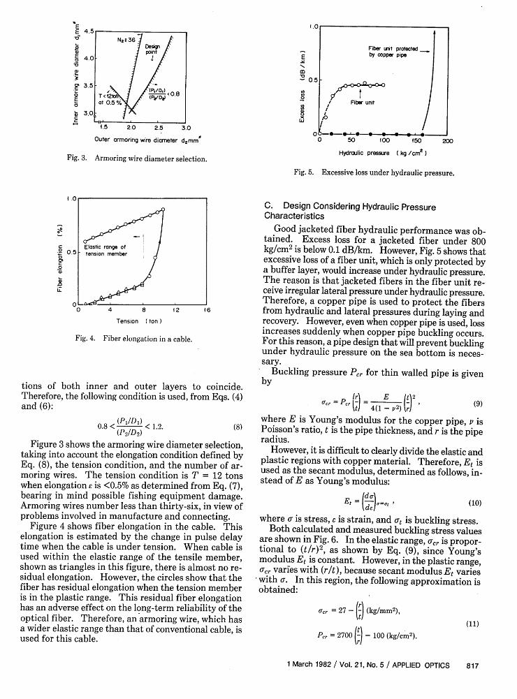
Fig. 3. Armoring wire diameter selection.
200
Hydraulic pressure ( kg /cm2 )
Fig. 5. Excessive loss under hydraulic pressure.
4 .0
rec Elastic range of0 0.5 tension member
or
0'C0
a)
00 4 8 42 46
Tension (ton
Fig. 4. Fiber elongation in a cable.
tions of both inner and outer layers to coincide.Therefore, the following condition is used, from Eqs. (4)and (6):
0.8 < (Pl/D0) < 1.2. (8)(P 2/D2 )
Figure 3 shows the armoring wire diameter selection,taking into account the elongation condition defined byEq. (8), the tension condition, and the number of ar-moring wires. The tension condition is T = 12 tonswhen elongation E is <0.5% as determined from Eq. (7),bearing in mind possible fishing equipment damage.Armoring wires number less than thirty-six, in view ofproblems involved in manufacture and connecting.
Figure 4 shows fiber elongation in the cable. Thiselongation is estimated by the change in pulse delaytime when the cable is under tension. When cable isused within the elastic range of the tensile member,shown as triangles in this figure, there is almost no re-sidual elongation. However, the circles show that thefiber has residual elongation when the tension memberis in the plastic range. This residual fiber elongationhas an adverse effect on the long-term reliability of theoptical fiber. Therefore, an armoring wire, which hasa wider elastic range than that of conventional cable, isused for this cable.
C. Design Considering Hydraulic PressureCharacteristics
Good jacketed fiber hydraulic performance was ob-tained. Excess loss for a jacketed fiber under 800kg/cm2 is below 0.1 dB/km. However, Fig. 5 shows thatexcessive loss of a fiber unit, which is only protected bya buffer layer, would increase under hydraulic pressure.The reason is that jacketed fibers in the fiber unit re-ceive irregular lateral pressure under hydraulic pressure.Therefore, a copper pipe is used to protect the fibersfrom hydraulic and lateral pressures during laying andrecovery. However, even when copper pipe is used, lossincreases suddenly when copper pipe buckling occurs.For this reason, a pipe design that will prevent bucklingunder hydraulic pressure on the sea bottom is neces-sary.
Buckling pressure Pr for thin walled pipe is givenby
Ucr =Pcr( = 4(1- E2) ()29
where E is Young's modulus for the copper pipe, v isPoisson's ratio, t is the pipe thickness, and r is the piperadius.
However, it is difficult to clearly divide the elastic andplastic regions with copper material. Therefore, Et isused as the secant modulus, determined as follows, in-stead of E as Young's modulus:
E (de [tde7 J -'
(10)
where a is stress, e is strain, and at is buckling stress.Both calculated and measured buckling stress values
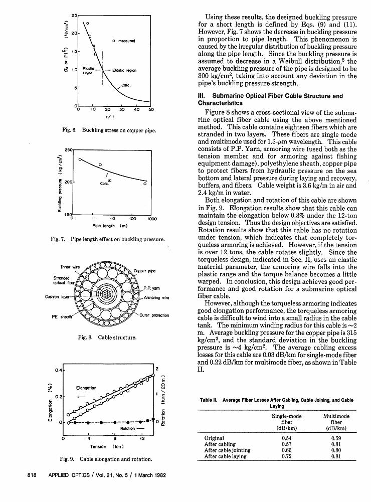
are shown in Fig. 6. In the elastic range, O'cr is propor-tional to (t/r) 2 , as shown by Eq. (9), since Young'smodulus Et is constant. However, in the plastic range,0rcr varies with (r/t), because secant modulus Et varieswith . In this region, the following approximation isobtained:
acr = 27 - (kg/mm2 ),
t (11)Pcr = 2700 () - 100 (kg/cm 2).
1 March 1982 / Vol. 21, No. 5 / APPLIED OPTICS 817
an
T0 2 < 36 .A
T< 2
at05%
F
(9)
aE. 20
0 measured
'1- 15 - \a.0
o Plastic... Elastic region1~10region I5 . lc
o to 20 30 40 50r/ t
Fig. 6. Buckling stress on copper pipe.
Zoo.
N-
tL'
in
200F
0.{ 4. 4OPipe length (m)
400 4000
Fig. 7. Pipe length effect on buckling pressure.
Cushion wire
protection
Fig. 8. Cable structure.
-e
0
w0c)
0 4 8 42
Tension (ton )
Using these results, the designed buckling pressurefor a short length is defined by Eqs. (9) and (11).However, Fig. 7 shows the decrease in buckling pressurein proportion to pipe length. This phenomenon iscaused by the irregular distribution of buckling pressurealong the pipe length. Since the buckling pressure isassumed to decrease in a Weibull distribution,8 theaverage buckling pressure of the pipe is designed to be300 kg/cm2, taking into account any deviation in thepipe's buckling pressure strength.
III. Submarine Optical Fiber Cable Structure andCharacteristics
Figure 8 shows a cross-sectional view of the subma-rine optical fiber cable using the above mentionedmethod. This cable contains eighteen fibers which arestranded in two layers. These fibers are single modeand multimode used for 1.3-gm wavelength. This cableconsists of P.P. Yarn, armoring wire (used both as thetension member and for armoring against fishingequipment damage), polyethylene sheath, copper pipeto protect fibers from hydraulic pressure on the seabottom and lateral pressure during laying and recovery,buffers, and fibers. Cable weight is 3.6 kg/m in air and2.4 kg/m in water.
Both elongation and rotation of this cable are shownin Fig. 9. Elongation results show that this cable canmaintain the elongation below 0.3% under the 12-tondesign tension. Thus the design objectives are satisfied.Rotation results show that this cable has no rotationunder tension, which indicates that completely tor-queless armoring is achieved. However, if the tensionis over 12 tons, the cable rotates slightly. Since thetorqueless design, indicated in Sec. II, uses an elasticmaterial parameter, the armoring wire falls into theplastic range and the torque balance becomes a littlewarped. In conclusion, this design achieves good per-formance and good rotation for a submarine opticalfiber cable.
However, although the torqueless armoring indicatesgood elongation performance, the torqueless armoringcable is difficult to wind into a small radius in the cabletank. The minimum winding radius for this cable is -2m. Average buckling pressure for the copper pipe is 315kg/cm2, and the standard deviation in the bucklingpressure is -4 kg/cm2 . The average cabling excesslosses for this cable are 0.03 dB/km for single-mode fiberand 0.22 dB/km for multimode fiber, as shown in TableII.2
E0W
iN
'0E
Fig. 9. Cable elongation and rotation.
Table II. Average Fiber Losses After Cabling, Cable Joining, and CableLaying
Single-mode Multimodefiber fiber
(dB/km) (dB/km)
Original 0.54 0.59After cabling 0.57 0.81After cable jointing 0.66 0.80After cable laying 0.72 0.81
818 APPLIED OPTICS / Vol. 21, No. 5 / 1 March 1982
0
"lICaic. 0
I -o

0.
0.
0.4
C
.5
-0.to 20
Temperature itC )30
60
f 40
a)
C0 20a)
0
Fig. 10. Cable temperature characteristics.
1 2 3
Cable length ( kim)
Fig. 12. Cable angle at water surface.
2
4 5 8= 6 7 34 5~ 6 7 3
I Optical fiber2. Fiber splice3. Fiber storage bobbin4. Optical fiber cable5. Armoring wire6. Copper pipe of the cable7. Housing8. Boot
Fig. 11. Cable splice structure.
Figure 10 shows the temperature characterisitics forthis cable in the 10-30°C temperature range. Thisfigure indicates that the temperature dependence of theoptical loss is almost zero in this temperature range.
IV. Cable Laying Results
The 10.2-km length cable was laid in Sagami Bay forthe field test in 1980. Maximum water depth is -240in. This cable has two cable joints whose diagram isshown in Fig. 11. The cable laying speed was at 3 knots.However, speed was reduced to 1 knot when laying thecable joints to ensure proper handling.
The cable angle at the water surface when laying isshown in Fig. 12. With 3-knot ship speed, cable angle0 at the water surface proved to be .350. Hydrody-namic constant H is -100 (degree knot) from
H = V, (12)
where H is the hydrodynamic constant, V is the ship'sspeed, and 6 is the cable angle at the water surface.Equation (12) indicates that value is almost equal to200 when the ship speed V = 5 knots. This means thatgood cable laying will be attained, even with suchhigh-speed laying as 5 knots.
Figure 13 shows the cable laying length, cable layingtension, and cable weight in water (wh). Increasingstress on sections A and B was caused by the tensionapplied to the cable when veering the ship to preventkinks.
Figures 14 and 15 show single-mode fiber losses andmultimode fiber losses during cabling and laying pro-
C
Ca)
0 2 4 6 8 40
Cable length. (km)
Fig. 13. Cable laying tension.
cesses, respectively. Table II shows the average losschange during cabling and laying processes. Thesefigures and Table II indicate that multimode fiber losschange was larger than that for single-mode fiber duringthe cabling process. However, during the cable joiningprocess, splicing loss for single-mode fiber was greaterthan that for multimode fiber, resulting from the dif-ficulty encountered in single-mode fiber splicing.
These results show that during the cable laying pro-cess excess loss for single-mode fiber was somewhatgreater than that for multimode fiber. However, excessloss for single-mode fiber was <0.1 dB/km.
A change in the baseband width for multimode fibersduring the cable laying process is shown in Fig. 16.These results indicate that there is almost no change inthe baseband width and agree with the slight excess lossduring cable laying shown in Figs. 14 and 15.
In conclusion, tension caused by the submerged cableweight is only -1 ton because water depth is <240 in.However, the large strain 0.1-0.5%, as shown in Fig. 17,is observed partially in the optical fiber since tension,caused by the changes in both ship's speed and direc-tion, varies rapidly as shown in Fig. 13. In such a severecondition, it is not unusual for the fiber to break and theoptical power may vary.
V. Residual Fiber ElongationAccumulated residual fiber elongation is shown in
Fig. 17 as well as water depth distribution. This re-
1 March 1982 / Vol. 21, No. 5 / APPLIED OPTICS 819
N
in
-J
I h
I -0- Multi -mode fiber40- 2. -0n- Single -mode fiber
I :0.851,m, 2.3 rm
D -
00 0
0 0
Ship speed 3kt
4
- Cable tensionw h w submerged
A i cable weight
2 ocean
Ados l
Ot.....
.. _

2 3 4 5 6 7 8 9 014Stage
Fig. 14. Single-mode fiber losses during cabling and layingprocess.
Fig. 15. Multimode fiber losses during cabling and laying process.
.0
200
450
100
50
OL
commen
4 2 3 4
Staget )I. After cabling2. In cable ship tonk3. Laying4. 43 days after laying.
Fig. 16. Change in baseband width for multimode fiber during ca-bling process.
-0
r0
W
304
201
404
100
S 200
, 3001 '
0.c5%
o -. 0.03% 02 % o.
H -Residuol elongation
* at eac4 sectionI% , . I I ' L
0 2 4 6 8 l((a) Cable length (km)
0 _
(b)2 4 6 8 4 0
Cable length (km)
Fig. 17. Residual fiber elongation during laying.
Cable ship
i Pulse ~~LDgenerator
I [Sm pling AP. I Delay oscilloscope _ _ _
L _ _ _ _ _ _
_ in the Sea
Cable
E I I abb endCable ersd
Fig. 18. Optical pulse delay time measurement diagram for residualfiber elongation.
sidual elongation is estimated by changes in the pulsedelay time using the measurement method shown in Fig.18. Comparison between cable tension in Fig. 13 andresidual fiber elongation in Fig. 17 indicates that re-sidual fiber elongation, divided into five sections by thecable laying method, agrees with cable tension.
The residual fiber elongation is connected with slack,which is extra cable length resulting from cable shipmovement during cable laying. This slack is deter-mined by the cable payout speed, ship speed, and theslope of the sea bottom. In this cable laying process,payout slack e, is determined to be 2% on the descendingsea bottom slope and 0% on an ascending slope.
Slack Eb on the sea bottom is expressed as9
sinO + sin6 i 1l
sin(O + 5)(13)
where is the slope angle of the sea bottom shown in Fig.19. As shown in Fig. 12, cable angle at the water sur-face was 35°. The average down slope angle on the seabottom was 2.5°, and the average up slope angle was3.80. By substituting these values, slack Eb on the seabottom is 0.6% for the down slope and 2.0% for the upslope. These results agree with residual fiber elonga-
820 APPLIED OPTICS / Vol. 21, No. 5 / 1 March 1982
E
Nin
0'a_
E
-
in
Stage
at 1.3pm
aver.
min.
L'10.2 kmI l
. . .
R . .
o
F2 (
I

h
Fig. 19. Cable laying illustration.
tion shown in Fig. 17; that is, the smaller the slack eb, thelarger the residual fiber elongation. To minimize theresidual fiber elongation, it seems necessary to pay outenough slack, taking into consideration the ship's speed,cable laying speed, and slack control ability.
VI. Conclusion
Structural design methods are proposed for subma-rine optical fiber cable which take into account sup-pressing cable elongation under tension and excess lossunder hydraulic pressure. Cabling excess loss in cablemanufacture using this design was <0.3 dB/km. A10.2-km length of this cable was laid in Sagami Bay inJapan. The average loss of the single-mode fibers afterlaying was 0.72 dB/km, and the average loss of themultimode fibers was 0.81 dB/km for 1.3 -btm wave-length. These results indicate that low loss and highcapacity submarine cable transmission lines can beachieved with optical fiber. Moreover, as the resultsof 10.2-km length cable laying experiment indicate, therelation obtained between the cable payout slack andthe residual fiber elongation clarifies the necessary cablepayout slack to minimize residual fiber elongation.
The authors intend to study improvements in cablestructure and long-term reliability for cables and joinsunder the sea.
The authors thank H. Fukutomi, Director of OutsidePlant Development Division, and Y. Kato, Deputy Di-rector of Outside Plant Development Division for theirguidance during this work. The authors also thankFurukawa Electric Co., Sumitomo Electric Industries,and Fujikura Cable Works for production of opticalfiber and Ocean Cable Co., Ltd. for production of sub-marine optical fiber cable.
References
1. N. Kojima, Y. Negishi, K. Iwabuchi, T. Yabuta, 0. Kawata, K.Yamashita, K. Funaki, and M. Inoue, "Sea Trial of SubmarineOptical Fiber Cable," in Technical Digest, Sixth ECOC, U. York(1980).
2. T. Yabuta, K. Yamashita, 0. Kawata, K. Iwabuchi, Y. Negishi, andN. Kojima, "Structure Design of Submarine Optical Fiber Cable,"in Technical Digest, Third International Conference 10OC(Optical Society of America, Washington, D.C., 1981), paperMD2.
3. R. F. Gleason, R. C. Mondello, B. W. Fellows, and D. A. Hadfield,"Design and Manufacture of an Experimental Lightguide Cablefor Undersea Transmission Systems," paper presented atTwenty-eighth International Wire & Cable Symposium, CherryHill, N.J., Nov. 1979.
4. P. Worthington, "Installation of a Trial Optical Fiber Cable De-signed for Transoceanic Submarine Telecommunications Sys-tems," paper presented at Twenty-eighth International Wire &Cable Symposium, Cherry Hill, N.J., Nov. 1980.
5. N. Kojima, Y. Negishi, K. Iwabuchi, and T. Yabuta, "Designingon Submarine Optical Cables," Tech. Rep., IECE Japan, CS79-208(1980), in Japanese.
6. T. Yabuta, 0. Kawata, K. Yamashita, Y. Negishi, and Y. Funaki,"Designing of a Submarine Optical Fiber Cable," Tech. Rep., IECEJapan, CS79-151 (1979), in Japanese.
7. Y. Mitsunaga, Y. Katsuyama, and N. Ishida, Electron. Lett. 17,16 (1981).
8. 0. Kawata, K. Yamashita, Y. Miyajima, K. Ueno, and T. Miya,"Transmission and Mechanical Characteristics of SubmarineOptical Cable," Tech. Rep., IECE Japan, CS79-209 (1980), inJapanese.
9. N. Kojima, Y. Negishi, K. Iwabuchi, T. Yabuta, 0. Kawata, Y.Miyajima, K. Yamashita, and N. Yoshizawa, "Results of 10.2-kmSubmarine Optical Fiber Cable Laying," Tech. Rep., IECE Japan,CS80-237 (1980), in Japanese.
0
1 March 1982 / Vol. 21, No. 5 / APPLIED OPTICS 821