submersible pumps model s-500 series - multiquip · pdf filesubmersible pumps model s-500...
TRANSCRIPT

OPERATION AND PARTS MANUAL
Revision #0 (10/01/04)
Submersible PumpsModel S-500 Series
THIS MANUAL MUST ACCOMPANYTHE EQUIPMENT AT ALL TIMES.

PAGE 2 — S-500 SERIES SUBMERSIBLE PUMPS — OPERATION & PARTS MANUAL — REV. #0 (10/01/04)
© COPYRIGHT 2004, Multiquip INC.
Multiquip Inc, the MQ logo are registered trademarks of Multiquip Inc. and may not be used, reproduced, or altered without writtenpermission. All other trademarks are the property of their respective owners and used with permission.
This manual MUST accompany the equipment at all times. This manual is considered a permanent part of the equipment and shouldremain with the unit if resold.
The information and specifications included in this publication were in effect at the time of approval for printing. Illustrations arebased on the MQ Model S-500 Series Submersible Pumps. Illustrations, descriptions, references and technical data contained inthis manual are for guidance only and may not be considered as binding. Multiquip Inc. reserves the right to discontinue or changespecifications, design or the information published in this publication at any time without notice and without incurring any obligations.
To find the latest revision of thispublication, visit our website at:
www.multiquip.com
HERE'S HOW TO GET HELPPLEASE HAVE THE MODEL AND SERIAL
NUMBER ON-HAND WHEN CALLINGMULTIQUIP CORPORATE OFFICE18910 Wilmington Ave. 800-421-1244Carson, CA 90746 FAX: 310-537-3927Email: [email protected]: www.multiquip.com
PARTS DEPARTMENT800-427-1244 FAX: 800-672-7877310-537-3700 FAX: 310-637-3284
MAYCO PARTS800-306-2926 FAX: 800-672-7877310-537-3700 FAX: 310-637-3284
SERVICE DEPARTMENT800-421-1244 FAX: 310-537-4259310-537-3700
TECHNICAL ASSISTANCE800-478-1244 FAX: 310-631-5032
WARRANTY DEPARTMENT800-421-1244, EXT. 279 FAX: 310-537-1173310-537-3700, EXT. 279

S-500 SERIES SUBMERSIBLE PUMPS — OPERATION & PARTS MANUAL — REV. #0 (10/01/04) — PAGE 3
S-500 SERIES SUB. PUMP — TABLE OF CONTENTS
Submersible PumpComponent DrawingsS-500P, S-500UL, S-500CE Pump Assembly ... 26-29S-500P, S-500UL Electric Motor Assembly ....... 30-31S-500CE Electric Motor Assembly .................... 32-33
Terms and Condition of Sale — Parts .....................34
Multiquip S-500 SeriesSubmersible PumpsHere's How To Get Help ............................................ 2Table Of Contents ..................................................... 3Parts Ordering Procedures ....................................... 4Safety Message Alert Symbols ................................. 5Rules For Safe Operation ...................................... 6-7Dimensions ............................................................... 8Specifications (Pump/Control Box) ...........................9General Information ................................................10Components ............................................................11Float Switches .........................................................12Float Switch (Piggy-Back) .......................................13Float Switch (Control Box) ......................................14Operation ................................................................15Control Box Installation ..................................... 16-17Clean-up .................................................................18Maintenance ...........................................................19Troubleshooting (Pump)..........................................20Performance Curves ...............................................21Wiring Diagrams (Electric Motor/Control Box) ........22Explanation Of Codes In Remarks Column ............24Suggested Spare Parts ...........................................25
As a continuing effort to updateour parts book, contact theMULTIQUIP literature departmentfor the latest revision of your"Operation and Parts Manual"
NOTE

PAGE 4 — S-500 SERIES SUBMERSIBLE PUMPS — OPERATION & PARTS MANUAL — REV. #0 (10/01/04)
S-500 SERIES SUB. PUMP — PARTS ORDERING PROCEDURES
When ordering parts,please supply the following information:
❒❒❒❒❒ Dealer account number❒❒❒❒❒ Dealer name and address❒❒❒❒❒ Shipping address (if different than billing address)❒❒❒❒❒ Return fax number❒❒❒❒❒ Applicable model number❒❒❒❒❒ Quantity, part number and description of each part❒❒❒❒❒ Specify preferred method of shipment:
✓ FedEx or UPS Ground✓ FedEx or UPS Second Day or Third Day✓ FedEx or UPS Next Day✓ Federal Express Priority One✓ DHL✓ Truck
Direct TOLL-FREE accessto our Parts Department:
Toll-free nationwide — 800-427-1244
Toll-free FAX — 800-6-PARTS-7 (800/672-7877)
MULTIQUIP INC.18910 WILMINGTON AVENUEPOST OFFICE BOX 6254CARSON, CALIFORNIA 90749310-537-3700 • 800-421-1244FAX: 310-537-3927E-MAIL: [email protected]: www.multiquip.com
Here’s how to get help...Please have the model and serial numberon hand when calling.
MULTIQUIP CORPORATE OFFICE18910 Wilmington Ave. 800-421-1244Carson, CA 90746 FAX: 310-537-3927Email: [email protected]: www.multiquip.comPARTS DEPARTMENT800-427-1244 FAX: 800-672-7877310-537-3700 FAX: 310-637-3284MAYCO PARTS800-306-2926 FAX: 800-672-7877310-537-3700 FAX: 310-637-3284SERVICE DEPARTMENT800-421-1244 FAX: 310-537-4259310-537-3700TECHNICAL ASSISTANCE800-478-1244 FAX: 310-631-5032WARRANTY DEPARTMENT800-421-1244, EXT. 279 FAX: 310-537-1173310-537-3700, EXT. 279
Note: Unless otherwise indicated by customer, allorders are treated as “Standard Orders”, and willship within 24 hours. We will make every effort to ship“Air Shipments” the same day that the order isreceived, if prior to 2PM west coast time. “StockOrders” must be so noted on fax or web forms.
Extra Discounts!All parts orders which include complete part numbers andare received by our automated web parts order system, orby fax qualify for the following extra discounts:
Ordered Standard Stock ordersvia orders ($750 list and above)
Fax 3% 10%
Web 5% 10%
Special freight allowanceswhen you order 10 or moreline items via Web or Fax!**FedEx Ground Service at no charge for freightNo other allowances on freight shipped by any other carrier.**Common nuts, bolts and washers (all items under $1.00list price) do not count towards the 10+ line items.
Place Your Parts Order Via Web or FaxFor Even More Savings!
(Domestic USA Dealers Only)
NOTE: DISCOUNTS ARE SUBJECT TO CHANGE

S-500 SERIES SUBMERSIBLE PUMPS — OPERATION & PARTS MANUAL — REV. #0 (10/01/04) — PAGE 5
S-500 SERIES SUB. PUMP — SAFETY MESSAGE ALERT SYMBOLS
Safety precautions should be followed at all times whenoperating this equipment. Failure to read and understand theSafety Messages and Operating Instructions could result ininjury to yourself and others.
FOR YOUR SAFETY AND THE SAFETY OF OTHERS!
This Owner's Manual has beendeveloped to provide completeinstructions for the safe and efficientoperation of the MultiquipModel S-500 Series SubmersiblePumps. Before using these pumps,ensure that the operating individualhas read and understands allinstructions in this manual.
SAFETY MESSAGE ALERT SYMBOLS
The three (3) Safety Messages shown below will inform youabout potential hazards that could injure you or others. TheSafety Messages specifically address the level of exposure tothe operator, and are preceded by one of three words: DANGER,WARNING, or CAUTION.
HAZARD SYMBOLS
Potential hazards associated with the S-500 series submersiblepumps operation will be referenced with Hazard Symbols whichappear throughout this manual, and will be referenced inconjunction with Safety Message Alert Symbols.
Rotating Parts
NEVER operate equipment with covers,or guards removed. Keep fingers, hands,hair and clothing away from all movingparts to prevent injury.NOTE
Accidental Starting
ALWAYS place the power source circuitbreaker or ON/OFF switch in the OFFposition, when the pump is not in use.
ALWAYS wear approved eye andhearing protection, if required.
Sight and Hearing hazard
Respiratory Hazard
ALWAYS wear approved respiratoryprotection, if required.
Equipment Damage Messages
Other important messages are provided throughout this manualto help prevent damage to your submersible pump, other property,or the surrounding environment.
This submersible pump, otherproper ty, or the surroundingenvironment could be damaged ifyou do not follow instructions.
NOTE
You WILL be KILLED or SERIOUSLY injured if you DONOT follow directions.
You CAN be KILLED or SERIOUSLY injured if you DONOT follow directions.
You CAN be INJURED if you DO NOT follow directions.
CAUTION
WARNING
CAUTION
DANGER

PAGE 6 — S-500 SERIES SUBMERSIBLE PUMPS — OPERATION & PARTS MANUAL — REV. #0 (10/01/04)
S-500 SERIES SUB. PUMP — RULES FOR SAFE OPERATION
Failure to follow instructions in this manual may lead to seriousinjury or even death! This equipment is to be operated bytrained and qualified personnel only! This equipment is forindustrial use only.
The following safety guidelines should always be used whenoperating the S- 500 Series Submersible Pumps:
GENERAL SAFETY
■ DO NOT operate or servicing this equipmentbefore reading this entire manual.
■ This equipment should not be operated by persons under 18years of age.
■ NEVER operate this equipment without proper protectiveclothing, shatterproof glasses, steel-toed boots and otherprotective devices required by the job.
■ NEVER operate this equipment when not feelingwell due to fatigue, illness or taking medicine.
■ NEVER operate this equipment under the influenceor drugs or alcohol.
■ NEVER use accessories or attachments, which are notrecommended by Multiquip for this equipment. Damage to theequipment and/or injury to user may result.
■ Manufacturer does not assume responsibility for any accidentdue to equipment modifications.
■ Whenever necessary, replace nameplate, operation and safetydecals when they become difficult read.
■ ALWAYS check the machine for loosened threads or boltsbefore starting.
■ NEVER operate the submersible pump in an explosiveatmosphere or near combustible materials. An explosion or firecould result causing severe bodily harm or even death.
■ ALWAYS make sure submersible pump is grounded.
■ NEVER use gas piping as an electrical ground.
■ DO NOT place hands or fingers inside pump when pump isrunning.
■ ALWAYS make certain that the voltage supplied to the pumpis correct. Always read the pump's nameplate to determinewhat the power requirements are. The S-500 seriessubmersible pumps require 115 VAC, 60 Hz (single-phase)for normal operation.
■ DO NOT restrict the flow of the discharge hose as it maycause overheating.
■ Be careful of discharge whipping under pressure.
■ Make sure pump installation is accordance with nationaland local electrical codes.
■ ALWAYS have a qualified electrician perform the pumpwiring installation.
■ ALWAYS mount the control box in a vertical positionprotected from the elements.
■ NEVER handle pump's AC power cord with wet hands.
■ NEVER let an extension cord or plug connection lay in water.
■ NEVER stand in water while AC power cord is connectedto a power source.
■ NEVER use a pump with a defective, frayed power cord.Check the power cord on the pump for cuts in the insulation.
■ NEVER use a extension cord that is frayed or damagedwhere the insulation has been cut.
■ ALWAYS make certain that proper extension cord has beenselected for the job. See Table 4.
■ NEVER attempt to use the power cord as a lifting or loweringdevice for the submersible pump.
■ When raising or lowering of the submersible pump isrequired, always attach an adequate rope or lifting deviceto the correct lifting point (handle) on the pump.
■ ALWAYS place the pump in an upright position on a platformbefore using. The platform will prevent the pump fromburrowing itself on soft sand or mud.
■ NEVER operate pump on its side.
■ DO NOT allow the pump to freeze in water.
■ NEVER leave an open pump chamber unattended.
■ The electrical voltage required to operate the pump cancause severe injury or even death through physical contactwith live circuits. ALWAYS disconnect the electrical powerfrom the pump before performing maintenance on the pump.
CAUTION

S-500 SERIES SUBMERSIBLE PUMPS — OPERATION & PARTS MANUAL — REV. #0 (10/01/04) — PAGE 7
S-500 SERIES SUB. PUMP — RULES FOR SAFE OPERATION
. Emergencies
■ ALWAYS know the location of the nearest fire extinguisher.
■ ALWAYS know the location of the nearest first aid kit.
■ In emergencies always know the location of thenearest phone or keep a phone on the job site.Also know the phone numbers of the nearestambulance, doctor and fire department. Thisinformation will be invaluable in the case of anemergency.
■ ALWAYS make sure that electrical circuits are properlygrounded per the National Electrical Code (NEC) andlocal codes before operating pump. Severe injury or deathby electrocution can result from operating an ungroundedpump.
■ NEVER use this pump to remove water from a swimming poolwhen people are in the water.
■ ALWAYS be sure the operator is familiar with proper safetyprecautions and operations techniques before usingsubmersible pump.
■ ALWAYS check pump oil level only when pump is cool.Expansion due to heat may cause hot! oil to spray from the oilplug when the oil plug is removed.
■ DO NOT attempt to thaw-out a frozen pump by using a torchor other source of flame. Application of heat in this mannermay heat the oil in the seal cavity above the critical point,causing pump damage.
■ DO NOT pump water greater than 104° Fahrenheit. Also DONOT pump liquids containing acid or alkali.
■ ALWAYS check strainer before pumping. Make sure straineris not clogged. Remove any large objects, dirt or debris fromthe strainer to prevent clogging.
■ ALWAYS use a large basket strainer when pumping waterthat contain large debris.
■ ALWAYS flush pump after use when pumping waterconcentrated with heavy debris. Flush with clean freshwater. It is very important to always flush the pump beforeturning it off to prevent clogging.
■ ALWAYS store equipment properly when it is not being used.Equipment should be stored in a clean, dry location out of thereach of children.
■ ALWAYS read, understand, and follow procedures inOperator’s Manual before attempting to operate equipment.
Maintenance Safety■ NEVER lubricate components or attempt service on a running
machine.
■ ALWAYS allow the machine a proper amount of time to coolbefore servicing.
■ Keep the machinery in proper running condition.
■ Fix damage to the machine immediately and always replacebroken parts.

PAGE 8 — S-500 SERIES SUBMERSIBLE PUMPS — OPERATION & PARTS MANUAL — REV. #0 (10/01/04)
S-500 SERIES SUB. PUMP — DIMENSIONS
Figure 1. S-500P, S-500UL Dimensions

S-500 SERIES SUBMERSIBLE PUMPS — OPERATION & PARTS MANUAL — REV. #0 (10/01/04) — PAGE 9
S-500 SERIES SUB. PUMP — SPECIFICATIONS
1. Motor Rotation – Upon start-up, the pump "kicks" in the opposite direction of motor rotation. The correct rotation iscounterclockwise (CCW) as viewed from the impeller end of the pump.
2. Mechanical Oil Seal – Use a good grade 10 weight non-detergent hydraulic oil (i.e. Shell Turbo 32 or equivalent). Fill oil cavity75% to 85% full (allow air space for expansion).
3. Control Box - Control box (Table 2) may be required for certain pumping applications.
snoitacificepSxoBlortnoC.2elbaT
.oNledoM epyTegatloV ASC/LUdetsiL
lamrehTdaolrevOnoitcetorP
taolFhctiwS
ytilibapaC
3BC -elgniSzH06,CAV511esahP SEY ON SEY
SNOITACIFICEPS.1ELBAT
ledoM P005-S LU005-S
epyTlagufirtneC
pmuPelbisrembuSlagufirtneC
pmuPelbisrembuS
rellepmI rebbuR rebbuR
eziSegrahcsiD&noitcuS )mm15(.ni00.2 )mm83(.ni05.1
yticapaCgnipmuPmumixaMetunim/snollag16)etunim/sretil032(
etunim/snollag36)etunim/sretil832(
retemaiDsdiloS.xaM A/N A/N
daeHxaM )sretem4.01(.tf43 )sretem0.11(tf63
rewoP )wk73.0(PH5.0 )wk73.0(PH5.0
esahPegatloV V511Ø1 V511Ø1
spmAgnitratS 4.05 1.44
spmAgninnuR 2.7 3.6
deriuqeRxoBlortnoC )3etoN(ON )3etoN(ON
noitcetorPdaolrevOlamrehT SEY SEY
noitatoR )1etoN(WCC )1etoN(WCC
yticapaClaesliOlacinahceM )2etoN(.cc081 )2etoN(.cc051
ycneuqerFkcehC ).srh003(ylhtnoM ).srh003(ylhtnoM
)deepS(PMR 03-/+0553 03-/+0553
htgneLelbaCrewoP ).mc6.7(.TF52 ).mc6.7(.TF52
thgiewteNyrD ).gK01(.sbl22 ).gK5.9(.sbl12

PAGE 10 — S-500 SERIES SUBMERSIBLE PUMPS — OPERATION & PARTS MANUAL — REV. #0 (10/01/04)
S-500 SERIES SUB. PUMP — GENERAL INFORMATION
Introduction
The Multiquip Model S-500 series submersible pumps aredesigned to pump water and is used for the draining (de-watering) of swimming pools, well casings construction sites,cofferdams, manholes, transformer vaults and excavations.
A rubber type impeller is attached to the output shaft of a 0.5 HPelectric motor which provides adequate power for generalpurpose pumping. This submersible pump is supplied completewith an electric power cable, and a discharge port located at thetop of the pump which accepts a 2-inch hose.
This pump is ideal for portability because of its light weight andcarrying handle. For reliability and long life, a mechanical sealprovides shaft sealing, with an oil chamber separating the pumpsection from the motor.
The pump when in use, should be installed as free standing(upright position) on its strainer base. A 2-inch discharge hose(not supplied) should be connected to the discharge port locatedon top of the pump. The discharge hose should be adequatelysupported to avoid stress on the pump.
For maximum water flow, the discharge hose should be kept asshort as possible, and with minimum elevation above the pump.Remember as the length and/or height of the discharge hose isincreased, the flow of water will be reduced. Also any reductionin the hose size, and any fittings such as valves or outlet nozzles,will restrict the water flow.
To avoid back-siphonage when the pump is switched off, ensurethat the end of the discharge hose is installed above the waterlevel at the final discharge point.
When the pump is switched off, the water remaining in the hosewill run back through the pump. This can be avoided by placinga non-return valve in the hose nearest the pump.
NEVER use this submersible pump to pump flammable liquidsor operate in a explosive or flammable environment.
Avoid using this pump in conditions where mud, grit, silt or otherdebris are present. These conditions could cause blockage andcause excessive pump wear.
DO NOT install the pump directly into an area where there is aheavy build-up of mud, grit, silt or debris. If this condition is present,install the pump on a platform before operating.
This pump must always be positioned on a platform in an uprightposition. NEVER operate the pump by a suspended rope. Toprevent large solids from entering the pump, install a wire meshscreen or similar barrier around the pump.
If the pump was used to pump water containing mud, silt, useclean water to flush out the pump after each use.
DO NOT allow the pump to run dry, as this will damage thepump. During maintenance, dry running is permissible but onlyfor a few seconds.
NEVER lift the pump by its electrical power cord. ALWAYS liftthe pump by its carrying handle or attach a rope to the carryinghandle.
A pump fully submerged in liquid will not freeze, unless the liquidfreezes. DO NOT allow a partially submerged pump to freeze.The expansion of water freezing in the volute may crack thepump, causing expensive repairs. If there is any danger of thepump being subjected to freezing temperatures, lift the pumpfrom water and allow it to drain thoroughly.
If the pump jams or the pump rotor locks for any reason,disconnect the pump from the power source immediately.Allowing the pump motor to cycle ON and OFF under an overloadcondition can burn out the motor.
When replacement of nuts and bolts is required, use onlyrecommended parts as referenced in the parts section of thismanual. This pump uses metric threads. DO NOT use Englishmeasurement threads.
Control Box Installation Warnings
When installing the CB3 control box, thepossibility exists of electrical shock,electrocution and possibly death! NEVER haveuntrained personnel perform the installation.ALWAYS have qualified service personnel (licensedelectrician) perform the installation.
Explosion or Fire Hazard exists if thispump is used with flammable liquids. DONOT use this pump with flammableliquids. DO NOT install this pump inhazardous locations as defined by the National ElectricalCode, ANSI/NFPA 70.
Failure to follow the above referenced precautions could resultin serious injury or death! Replace pump cord immediately ifcord becomes damaged or severed. This pump must be installedin accordance with National Electric Code ANSI/NFPA 70 so asto prevent moisture from entering or accumulating with the boxes,conduit bodies fittings, float housing or cable.
DANGER
WARNING

S-500 SERIES SUBMERSIBLE PUMPS — OPERATION & PARTS MANUAL — REV. #0 (10/01/04) — PAGE 11
S-500 SERIES SUB. PUMP — COMPONENTS
6. Carrying Handle – Always carry the submersible pumpby its handle. NEVER! carry the pump by its power cord.Carrying or lifting the pump by the power cord, will causeundue stress on the cord, and ultimately the cord willbecome dislodged from the pump.
7. Thermal Overload Protection – This pump is equippedwith thermal overload protection that will shutdown themotor in the event of high operating temperatures. The motorwill automatically restart once the temperature returns toan acceptable operating temperature.
8. Mechanical Oil Seal – This oil filled seal provideslubrication when running the pump dry. NEVER! run thepump dry. Running the pump dry will cause severe damageto the pump.
Figure 2. Submersible Pump Components
Figure 2 shows the location of the basic components, for theS-500 series submersible pumps. Listed below is a briefexplanation of each component.
1. Strainer Base – This strainer base is made of stainlesssteel which is resistant to hardware corrosion. DO NOTpump large objects or debris with this pump. This pump isfor pumping water only. For de-watering purposes, alwaysplace the strainer base on a platform.
2. Volute/Impeller – Impellers are constructed of high-chromeductile iron to minimizes wear and prolong service life.
3. Electric Motor – All S-500 series submersible pumps utilizea 60 Hz, single-phase, 115 VAC, 0.5 HP electric motor.Consult with a licensed electrician before connectingmotor to a power source. Observe all city and local safetycodes.
4. Discharge Port – Connect a 2-inch hose to this port.Remember to adequately support the discharge hose toavoid stress on the pump.
5. AC Power Cable – This unit is supplied with a 25 ft.(7.6 meters) AC power cable. Always check the cable forsigns of wear. NEVER! use a defective power cable.Replace the cable immediately if the cable is worn ordefective.

PAGE 12 — S-500 SERIES SUBMERSIBLE PUMPS — OPERATION & PARTS MANUAL — REV. #0 (10/01/04)
S-500 SERIES SUB. PUMP — FLOAT SWITCHES
Float Switch Theory
Mercury monitoring is a mercury-switch actuated, liquid levelcontrol that has proven to be more economical and longer lastingthan other types of liquid-level control systems, easily replacingand improving upon diaphragm switches, air bubble systemsand electromechanical switches most often relied upon in thepast.
How It Works
There is a tilt-sensitive mercury switch hermetically sealed withineach float. As the liquid level (water) rises or falls, the float changesits angle until the mercury switch makes (closed, Figure 4) orbreaks (open, Figure 5) the circuit. Maximum pumping range is120 degrees. See Figure 3 below.
Figure 3. Pumping Range (Float Switch)
Figure 5. Float Switch (Open)
Figure 4. Float Switch (Closed)
Design Features
Constructed of rigid, durable ABS polymer ultrasonically welded.The all-steel mercury switch is held by positioning pins. Interioris filled with cell foam.
■ Suitable for most liquid environments.
■ Hermetically sealed.
■ Thick-walled non-corrosive PVC plastic enclosure.
■ Pressure tested to 60 ft. (18.2 meters).
■ Mercury switch reliability, proven to 500,000 cycles.
■ Standard SJO, 16-gauge, 2 conductor cord (20 ft./6.09 m).
Pumping Range
The pumping range of the pump is determined by the float switchtether cord. Use Table 3 as guideline to determine your requiredpumping range. Pumping ranges are based on non-turbulentconditions. Range may vary due to water temperature and cordshape. Please note as the tether length increases, so does thevariance of the pumping range.
egnaRgnipmuP.3elbaT
htgneLrehteT.ni2
.mc80.5.ni4
.mc61.01.ni6
.mc42.51.ni8
.mc23.02.ni01
.mc4.52.ni21
.mc84.03.ni41
.mc65.53.ni61
.mc46.04
egnaRgnipmuP.ni6
.mc42.51.ni01
.mc4.52.ni41
.mc65.53.ni81
.mc27.54.ni22
.mc88.55.ni72
.mc85.86.ni13
.mc47.87.ni53
.mc9.88

S-500 SERIES SUBMERSIBLE PUMPS — OPERATION & PARTS MANUAL — REV. #0 (10/01/04) — PAGE 13
Float Switch
Single or dual control float switches can be used for the unattended operation of the submersible pump. When using the piggy-back power configuration (plug), the S-500 series pumps DO NOT require the use of a control box. In this configuration (piggy-back),the SW-1 (single float switch) or SW-2 (dual float switch) are required. Figure 6 is an example of a single float switch application.
S-500 SERIES SUB. PUMP — FLOAT SWITCH (PIGGY-BACK)
Figure 6. Single Float SwitchApplication Diagram
Figure 6 shows a single float switchapplication. For dual float switchcapability use a Model SW-2 mercurytype float switch .
NOTE
Mounting The Float Switch
1. Determine the required cord tether length as shown inFigure 6 and Table 3.
2. Place the cord into the clamp as shown in Figure 6.
3. Secure the clamp to the discharge hose as shown in Figure5. DO NOT install cord under hose clamp.
4. Using a screwdriver, tighten the hose clamp. DO NOT over-tighten. Make sure the float cord is not allowed to touch theexcess hose clamp band during operation.

PAGE 14 — S-500 SERIES SUBMERSIBLE PUMPS — OPERATION & PARTS MANUAL — REV. #0 (10/01/04)
Control Box (CB3)
For special remote pumping applications of the submersible pump, a control box (Model CB3) may be required. This water resistantcontrol box provides watertight housing and glands to prevent water from leaking into the box, and a float switch interface. When usingthe CB3 control box, only the SW-1WOP float switch (2) can be used (no plug, bare wires). Shown below (Figure 7) is a wiring layout ofthe CB3 control box. See page 22 for a wiring diagram of the control box.
S-500 SERIES SUB. PUMP — FLOAT SWITCH (CONTROL BOX)
Figure 7. CB3 Control Box and Dual Float SwitchApplication Diagram

S-500 SERIES SUBMERSIBLE PUMPS — OPERATION & PARTS MANUAL — REV. #0 (10/01/04) — PAGE 15
S-500 SERIES SUB. PUMP — OPERATION
Hose Connections
1. Connect a 2-inch hose to the discharge port on the pumpas shown in Figure 8. Make sure that the hose is attachedcorrectly to the discharge port.
Pump Power Connections (Piggy-Back Cord Only)
1. Make sure the circuit breaker supplying power to the pumpis in the OFF position.
2. Connect the float switch or switches to the AC powerreceptacle as shown in Figure 6.
Attaching Lifting Rope
1. Attach a suitable lifting cable (rope) to the carrying handle(Figure 8) on the pump and lower the pump into place. Forapplications where there is an excessive amount of mud, gritor silt, the use of a support platform is desirable. Whenpumping water from swimming pool type applications wherethere is little or no debris, the support platform is not required.
Figure 8. Submersible Pump Upright Position(Correct)
2. Make sure the pump is always placed in an upright position,not tilted (Figure 9). Never position the pump directly on a soft,loose bottom. Remember to attain maximum pumping ca-pacity and prevent excessive wear, position the pump so itwill not burrow itself into sand or clay.
Figure 9. Submersible Pump Upright Position(Incorrect)
3. If all of the pump's electrical requirements have been met,place the circuit breaker or power ON/OFF switch in the ONposition.
4. Wait a few seconds and water should begin to flow from thedischarge hose.
5. If water is not flowing from the discharge hose or not flowingfreely after a few minutes, remove the power from the pumpand check the system for leaks.
6. To stop the pump from pumping, place the circuit breakeror ON/OFF switch in the OFF position.
NEVER! grab or touch a live power cord (Figure 10). DONOT stand in water when connecting the pump's power cordinto a voltage source. The possibility exists of electricalshock, electrocution and possibly death!
POWERCORD
(POWER ON)
WETHANDS
Figure 10. Power Cord (Wet Hands)
DANGER

PAGE 16 — S-500 SERIES SUBMERSIBLE PUMPS — OPERATION & PARTS MANUAL — REV. #0 (10/01/04)
S-500 SERIES SUB. PUMP— CONTROL BOX INSTALLATION
The S-500 series submersiblepumps are also designed to workwith a control box (Model CB3). Thiscontrol box contains the necessaryelectronics (float switch connections) to operate the pump.Remember this control box contains hazardous voltages.Disconnect all sources of power before installing orservicing. There exists the possibility of electrocution,electric shock or burn, which can cause severe bodilyharm or even death!
This control box should only be installed or serviced by alicensed electrician or qualified personnel.
Control Box Mounting
Mount the control box in an upright vertical position. Make surethe control box is securely fastened to a flat surface, that is freeof dust, dirt, moisture or any elements that may contaminate orerode the electronic components of the control box.
Single-Phase Power Installation (Input)
All S-500 series submersible pumps require 115 V, 60 Hz.,single-phase power for normal operation.
If you cannot determine what your pump's powerrequirements are, look at the vendor supplied identificationname tag attached to the pump or please contact Multiquip'sService/Technical Assistance department.
Applying incorrect power (voltage phasing) to thesubmersible pump can cause severe damage to the pump.Please make sure that the correct voltage and phase aretransferred to the pump at all times.
Power Cord Requirements
When routing the 115 VAC, 60 Hz., single phase power via apower cord to the control box, ALWAYS use the correct wire size.Please reference Table 4 below (Cord Length/Wire Size) todetermine the correct wire size. Incorrect wire size can adverselyaffect the performance of the pump.
Connecting Dual float Switch (SW-1WOP) To Control Box
1. Remove the float switch input connector housing, thenroute the float switch wires through the cable gland on thecontrol box. Attach the wires of the float switch to theterminal block as indicated by Table 5 and Figure 6.
2. Tighten the connector housing to ensure a tight fit betweenthe cord and the connector body. This will prevent the cablefrom pulling out of the terminal block and also preventmoisture from entering the control box.
3. Determine the length of the float switch wires, then securefloat switch wires to pump discharge hose. See Figures 3and 6 and Table 3 to determine the pumping range.
EZISERIWDNAHTGNELDROC.4ELBAT S
SPMA .TF05 .TF001 .TF051
6 GWA61 GWA61 GWA41
8 GWA61 GWA41 GWA21
01 GWA61 GWA41 GWA21
21 GWA41 GWA41 GWA21
41 GWA41 GWA21 GWA01
61 GWA21 GWA21 GWA01
SNOITCENNOCHCTIWSTAOLF.5ELBAT S
HCTIWSTAOLF KCOLBLANIMRETREBMUN
TRATS )KCALB(1LANIMRET)ETIHW(2LANIMRET
POTS )ETIHW(7LANIMRET)KCALB(8LANIMRET
DANGER
CAUTION
CAUTION

S-500 SERIES SUBMERSIBLE PUMPS — OPERATION & PARTS MANUAL — REV. #0 (10/01/04) — PAGE 17
2. Remove the pump AC input connector housing from thecontrol box, then route the power cord through the cablegland on the control box.
3. Connect the pump power cord to the contactor as shown inFigure 7 and Table 7.
Connecting AC Power to the Control Box
1. The AC power cord (input) should have three wires. Eachwire is color coded. The colors are WHITE, BLACK andGREEN.
2. Remove the AC input connector housing from the controlbox, then route the power cord through the cable gland onthe control box.
3. Connect the AC power cord to the contactor as shown inFigure 7 and Table 6.
Electrical connections to the powersource should only be performed bya licensed electrician or qualifiedpersonnel.
3. Tighten the connector housing to ensure a tight fit betweenthe power cord and the connector body. This will preventthe cable from pulling out of the terminal block and alsoprevent moisture from entering the control box.
NOTE
4. Connect the other end of the AC power cord to the voltagesource. Remember to provide a means of disconnectingthe power from the control box (circuit breaker or quickdisconnect switch). Also make sure to provide a good earthground to the control box.
Connecting AC Power to the Pump
1. AC power is transferred to the pump via a contactor. Thecoil of the contactor is energized or de-energized by theopening and closing of the float switch contacts. The powercord should have three wires. Each wire is color coded.The colors are WHITE, BLACK and GREEN.
It is recommended that the power beingsupplied to the control box ALWAYSbe connected to a circuit breaker ora quick disconnect switch. Thissafety feature allows for quick removalof power from the control box in theevent of an emergency.
NOTE
Turning On The Pump
1. If all of the pump's electrical requirements have been met,place the circuit breaker or power ON/OFF switch in the ONposition.
2. The CB3 control box has an operation switch located onthe front cover. This switch has 3 positions, AUTO, MANUALand OFF. The AUTO position allows the pump to run in anunattended mode. The MANUAL position will let the pumprun without the float switches controlling the pump. When inthe manual mode be careful not to let the pump run dry.Severe damage to the pump may occur if it is allowed to rundry. NEVER let the pump run dry.
3. Place the operation switch in the AUTO position. The ACpower indicator lamp should be lit (ON).
4. Wait a few seconds and water should begin to flow from thedischarge hose.
5. If water is not flowing from the discharge hose or not flowingfreely after a few minutes, remove the power from the pumpand check the system for leaks.
6. To stop the pump from pumping, place the operation switchin the OFF position.
S-500 SERIES SUB. PUMP— CONTROL BOX INSTALLATION
REWOPTUPNICA.6ELBATROTCATNOCOTSNOITCENNOC S
ROLOCERIWELBAC ROTCATNOC
KCALB 1L
ETIHW 2L
NEERG DNUORG
REWOPTUPTUOCA.7ELBATPMUPOTSNOITCENNOC
ROLOCERIWELBAC ROTCATNOC
KCALB 1T
ETIHW 2T
NEERG DNUORG

PAGE 18 — S-500 SERIES SUBMERSIBLE PUMPS — OPERATION & PARTS MANUAL — REV. #0 (10/01/04)
S-500 SERIES SUB. PUMP — CLEAN-UP
Pump Shut-Down/Clean-up
1. Remove the power from the pump by turning off the circuitbreaker or switch that provides power to the pump. Remem-ber to make sure that hands are dry (not wet), and feet are notstanding in water when removing disconnecting power fromthe pump.
2. Using the lifting rope, lift the pump up from its current position.Remove the discharge hose from the discharge port on thepump.
3. Remove all power cables and float switches from the controlbox. Place cables and float switches in a suitable containerwhere they will not get damaged.
4. If the pump was used to pump mud, grit or silt, flush vigorouslywith clean water.
5. Remove the pump from the water. Wipe off any mud or debristhat might have attached itself to the pump.
6. Store pump in a clean dry place away from dirt and debris.

S-500 SERIES SUBMERSIBLE PUMPS — OPERATION & PARTS MANUAL — REV. #0 (10/01/04) — PAGE 19
S-500 SERIES SUB. PUMP — MAINTENANCE
LUBRICATION
To check the oil level of the mechanical seal perform thefollowing:
DISASSEMBLY
Refer to Figure 11 for location of parts to be removed.
1. Position pump upside down.
2. Remove strainer.
3. Remove casing.
4. Remove the pump impeller.
5. Remove the liner.
6. Remove the oil plug and packing.
OIL CHECK
1. Visually inspect oil plug hole to verify that oil cavity is fullenough to cover seal spring. Check every 300 hours, changehydraulic oil every 6 months (1,000 hours) or as needed.
2. While checking the hydraulic oil level, also check thecondition of the hydraulic oil in the seal cavity . Block theopening with a finger and roll pump to one side to drainoil into a small transparent container. If oil is cloudy or haswater in it, drain oil from pump cavity and replace hydrau-lic oil. Check the seal for wear damage.
3. If oil level is low fill with SAE 10 weight non-detergenthydraulic oil (i.e. Shell Turbo 32 or equivalent). Fill oil cavity75% to 85% full (allow air space for expansion). See Table1 for pump oil cavity capacity.
IMPELLER
1. Make sure the clearance between the impeller and thefriction disk is approximately .012 - .020 inches (.304 -.508 mm.)
2. If impeller is defective or badly worn, replace impeller imme-diately.
Figure 11. Checking Hydraulic Oil
FILL WITH 10 WEIGHT NON-DETERGENT HYDRAULICOIL. USE SHELL TURBO 32OR EQUIVALENT.
FILL TO 75-80% CAPACITYSEE TABLE 1 FOR FILLINGCAPACITY.
REMOVE FILL PLUG, ANDVISUALLY INSPECT THATOIL CAVITY IS FULL ENOUGHTO COVER SEAL SPRING.
CHECK HYDRAULIC OILEVERY 300 HOURS. CHANGEEVERY 6 MONTHS OR ASNEEDED.
DISCOLORATION OF OIL(MILKY) INDICATES A LEAKINGPUMP WATER SEAL.
S-500
S-500
POSITIONPUMP UPSIDE
DOWNSTEP 1
STEP 2
REMOVESTRAINER
REMOVECASING
STEP 3
REMOVEIMPELLER
STEP 4
REMOVELINER
STEP 5
CASINGCOVER
OILCAVITY
REMOVEOIL PLUG
ANDPACKING
STEP 6

PAGE 20 — S-500 SERIES SUBMERSIBLE PUMPS — OPERATION & PARTS MANUAL — REV. #0 (10/01/04)
S-500 SERIES SUB. PUMP — TROUBLESHOOTING
GNITOOHSELBUORTPMUP.8ELBAT
MOTPMYS MELBORPELBISSOP NOITULOS
tratSoTsliaFpmuP
?spma/egatlovtcerrocnI
gniebsi)esahp-elgnis,zH06,CAV511(egatlovreporptahtkcehCtnuomaetauqedanasierehttahtkcehcoslA.pmupehtotdeilppustiucricecruosrewopkcehC.pmupehtnurot)spma(tnerrucfo
.rekaerb
?snoitcennoclacirtcelekcehC .drocrewoptcepsni,gniriwkcehcsehctiwstaolfgnisufI
?esufrewopnwolB .esufnwolbfoesuackcehc,esufecalpeR
?dekcolrellepmI rellepmireporpmidnagniggolcrofkcehcdnadrocrewoptcennocsiD.ecivednoitcetorpdaolrevokcehC.pmupgolcnU.ecnaraelc
?sgnidniwrotomteWtsumecnatsisernoitalusnI.noitalusnirotomkcehcotretemitlumesUelbmessasid,wolsiecnatsiserfI.smhoagem51yletamixorppaeb
.mehtyrdotsgnidniwekabdnarotompmup
pmupdnarotomevitcefeD?sgniraeb
ecalpeR.sgniraebecalpernrowfi,raewgniraebevissecxerofkcehC.evitcefedfirotom
lluFrevileDotsliaFpmuPtuptuO
egrahcsiddetcirtserrodetsiwT?esoh
.enilesohmorfgolcevomeR.deknik-nutalfesohyaL
?reniartspmupdeggolC .reniartsnaelC
?egatlovwoL
egatloV.dezigrenesipmupelihwegatlovkcehcotretemtlovaesUnafI.)daoldnadaolon(ecruosrewopkcehC.%01±nihtiwebtsumgniyrrac-tnerrucetauqedasahtierusekam,desusidrocnoisnetxe
.4elbaTeeS.htgnelderiuqerehtrofyticapac
?nrowrellepmI .rellepmiecalpeR
liOlaeSniretaW?laesretawevitcefeD .laesretawecalpeR
?gulPlliFliOesooL .ylerucesnethgiT
Practically all breakdowns can be prevented by proper handling and maintenance inspections, but in the event of abreakdown, use Table 8 (Pump Troubleshooting) as a basic guideline for troubleshooting the pump. If the problem cannot beremedied, contact Multiquip's service department.

S-500 SERIES SUBMERSIBLE PUMPS — OPERATION & PARTS MANUAL — REV. #0 (10/01/04) — PAGE 21
Figure 12. Pump Performance Curves
S-500 SERIES SUB. PUMP — PERFORMANCE CURVES
0
0 10 20 30Capacity(US.Gacity(US.G.P.M)
60
40
20
TOTAL HEAD
CAPACITY
Max 34 FTMax 34 FT
Max 61 GMax 61 G.P.M
To
talH
ea
d(
ft)
Quantity (G.P.M)
ST-500P Performance Curve
0
0 10 30Capacity(US.G.P.M)
60
40
20
TOTAL HEAD
CAPACITY
Max 3536 FTMax 3536 FT
Max 63 GMax 63 G.P.M
To
talH
ea
d(
ft)
Quantity (G.P.M)
ST-500UL Performance Curve
20 40 50

PAGE 22 — S-500 SERIES SUBMERSIBLE PUMPS — OPERATION & PARTS MANUAL — REV. #0 (10/01/04)
S-500 SERIES SUB. PUMP — WIRING DIAGRAMS
LEAD WIRES
AC POWER CORD
U
V
BLACK (LINE)
WHITE (NEUTRAL)
GREEN (GROUND)
MAINCOIL
AUXILIARYCOIL
CENTRIFUGALSWITCH
COIL
L1T1
SUBMERSIBLEPUMP
1
2
3
4
5
6
7
8
STOPFLOAT
SWITCH(LOW)
T2
PUMPPOWERCORD
BLACK
WHITE
GREEN
CHASSISGND.
WHITE
BLACK
BLACK
POWERON
LAMP
BLACK
WHITE
BLA
CK
CONTACTOR
L2
EXTERNAL 1-PHASE(115 VAC, 60 Hz.)
POWER SOURCE
CIRCUITBREAKER
WHITE
BLACKL1
GROUND
L2
GREEN
OFF
MANUAL
AUTO
OPERATION SWITCH
WHITE
GND
BLACK
BLACK
INPUTPOWERCORD
GREEN
WHITE
STARTFLOAT
SWITCH(HIGH)
WHITE
BLACK
CONTROL BOX WIRING DIAGRAM
115 VAC, 60 Hz. ELECTRIC MOTORWIRING DIAGRAM
BLACK
CHASSISGND.
BLACK

S-500 SERIES SUBMERSIBLE PUMPS — OPERATION & PARTS MANUAL — REV. #0 (10/01/04) — PAGE 23
NOTE PAGE

PAGE 24 — S-500 SERIES SUBMERSIBLE PUMPS — OPERATION & PARTS MANUAL — REV. #0 (10/01/04)
S-500 SERIES SUB. PUMP — EXPLANATION OF CODE IN REMARKSCOLUMN
How to read the marks and remarks used in this partsbook.
Items Found In the “Remarks” Column
Serial Numbers-Where indicated, this indicates a serialnumber range (inclusive) where a particular part is used.
Model Number-Where indicated, this shows that thecorresponding part is utilized only with this specific modelnumber or model number variant.
Items Found In the “Items Number” ColumnAll parts with same symbol in the number column, *, #, +, %, or>, belong to the same assembly or kit.
The contents of this partscatalog are subject to changewithout notice.
NOTE
If more than one of the samereference number is listed, thelast one listed indicates newest(or latest) part available.
NOTE

S-500 SERIES SUBMERSIBLE PUMPS — OPERATION & PARTS MANUAL — REV. #0 (10/01/04) — PAGE 25
S-500 SERIES SUB. PUMP — SUGGESTED SPARE PARTS
S-500P/UL SUBMERSIBLE PUMP1 TO 3 UNITSQty. P/N Description1 ............ 020S500UL120 .............. AC CORD W/ GLAND1 ............ 020S500UL060 .............. MECHANICAL SEAL1 ............ 020S500UL074 .............. PACKING1 ............ 0202S500UL214 ............ PACKING1 ............ 020S500UL003 .............. IMPELLER

PAGE 26 — S-500 SERIES SUBMERSIBLE PUMPS — OPERATION & PARTS MANUAL — REV. #0 (10/01/04)
S-500P, S-500UL, S-500CE SUBMERSIBLE PUMP ASSY.
S-500P/UL/CE — ELECTRIC SUBMERSIBLE PUMP ASSY.
214
224
74
60
918
299
300
238
170
5
829
53
4
3
829894
893
895
7
3467
65
265
444 127
121
125
120
264
146
891
302
119
174
103
102
431
1

S-500 SERIES SUBMERSIBLE PUMPS — OPERATION & PARTS MANUAL — REV. #0 (10/01/04) — PAGE 27
S-500P, S-500UL, S-500CE SUBMERSIBLE PUMP ASSY.
NO PART NO PART NAME QTY. REMARK1 020S500UL001 CASING 13 020S500UL003 IMPELLER ........................................ 1 ...................... S-500P AND S-500UL3 020S500CE003 IMPELLER ........................................ 1 ...................... S-500CE ONLY4 020S500UL004 IMPELLER NUT 15 020S500UL005 IMPELLER NUT WASHER 17 020S500UL007 CASING COVER 134 020S500UL034 SCREW 353 020S500UL053 WASHER 160 020S500UL060 MECHANICAL SEAL 165 020S500UL065 PLUG 167 020S500UL067 PACKING 174 020S500UL074 PACKING 1102 020S500CE102 DISCHARGE PORT ......................... 1 ...................... S-500CE ONLY102 020S500P102 DISCHARGE PORT ......................... 1 ...................... S-500P ONLY102 020S500UL02 DISCHARGE PORT ......................... 1 ...................... S-500UL ONLY103 020S500UL103 PACKING 1119 020S500UL119 MOTOR ............................................ 1 ...................... S-500P AND S-500UL119 020S500CE119 MOTOR ............................................ 1 ...................... S-500CE ONLY120 020S500UL120 AC CORD W/CORD GLAND ........... 1 ...................... S-500P AND S-500UL120 020S500CE120 AC CORD W/CORD GLAND ........... 1 ...................... S-500CE ONLY121 020S500UL121 CORD CLAMP 1125 020S500UL125 SCREW 2 S-500P AND S-500UL125 020S500CE125 SCREW 2 S-500CE ONLY
S-500P/UL/CE — ELECTRIC SUBMERSIBLE PUMP ASSY.

PAGE 28 — S-500 SERIES SUBMERSIBLE PUMPS — OPERATION & PARTS MANUAL — REV. #0 (10/01/04)
214
224
74
60
918
299
300
238
170
5
829
53
4
3
829894
893
895
7
3467
65
265
444 127
121
125
120
264
146
891
302
119
174
103
102
431
1
S-500P/UL/CE — ELECTRIC SUBMERSIBLE PUMP ASSY.
S-500P, S-500UL, S-500CE SUBMERSIBLE PUMP ASSY.
S-500 SERIES SUBMERSIBLE PUMPS — OPERATION & PARTS MANUAL — REV. #0 (10/01/04) — PAGE 29
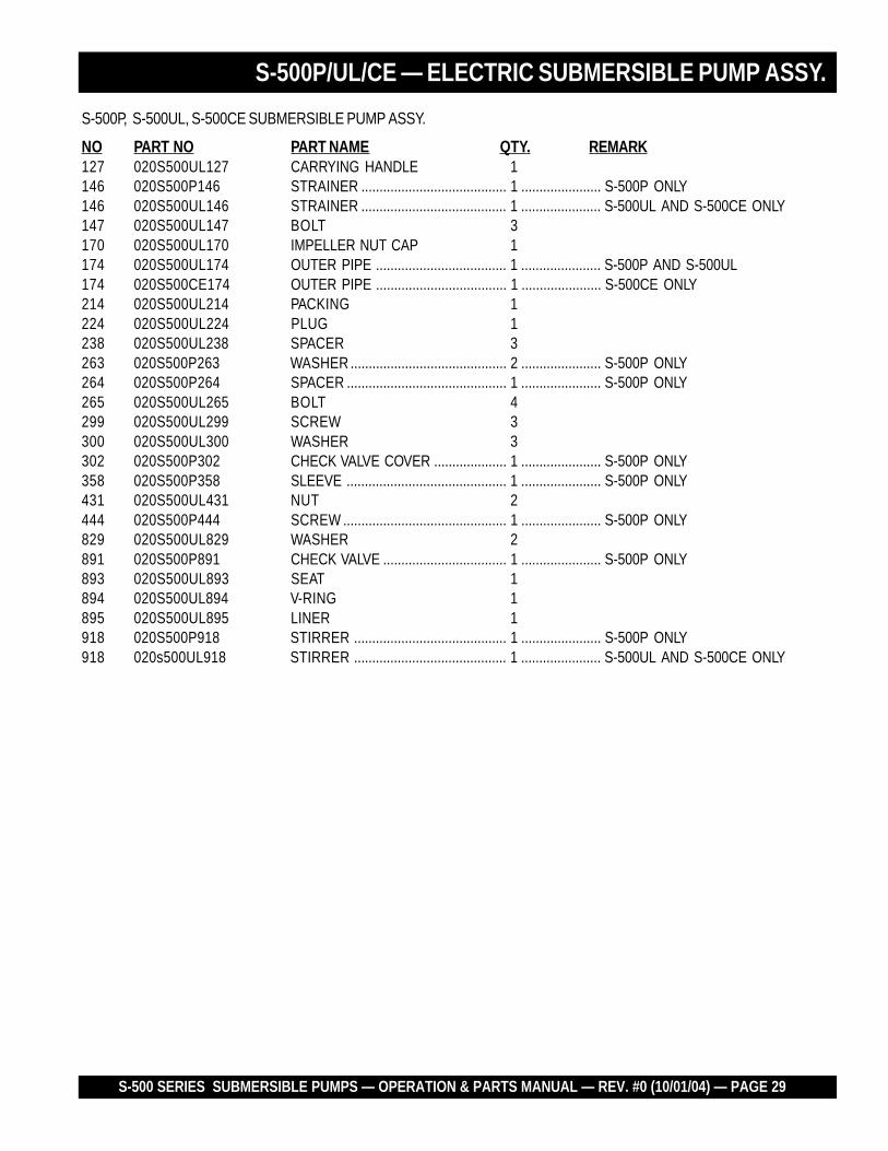
S-500P, S-500UL, S-500CE SUBMERSIBLE PUMP ASSY.
NO PART NO PART NAME QTY. REMARK127 020S500UL127 CARRYING HANDLE 1146 020S500P146 STRAINER ........................................ 1 ...................... S-500P ONLY146 020S500UL146 STRAINER ........................................ 1 ...................... S-500UL AND S-500CE ONLY147 020S500UL147 BOLT 3170 020S500UL170 IMPELLER NUT CAP 1174 020S500UL174 OUTER PIPE .................................... 1 ...................... S-500P AND S-500UL174 020S500CE174 OUTER PIPE .................................... 1 ...................... S-500CE ONLY214 020S500UL214 PACKING 1224 020S500UL224 PLUG 1238 020S500UL238 SPACER 3263 020S500P263 WASHER ........................................... 2 ...................... S-500P ONLY264 020S500P264 SPACER ............................................ 1 ...................... S-500P ONLY265 020S500UL265 BOLT 4299 020S500UL299 SCREW 3300 020S500UL300 WASHER 3302 020S500P302 CHECK VALVE COVER .................... 1 ...................... S-500P ONLY358 020S500P358 SLEEVE ............................................ 1 ...................... S-500P ONLY431 020S500UL431 NUT 2444 020S500P444 SCREW ............................................. 1 ...................... S-500P ONLY829 020S500UL829 WASHER 2891 020S500P891 CHECK VALVE .................................. 1 ...................... S-500P ONLY893 020S500UL893 SEAT 1894 020S500UL894 V-RING 1895 020S500UL895 LINER 1918 020S500P918 STIRRER .......................................... 1 ...................... S-500P ONLY918 020s500UL918 STIRRER .......................................... 1 ...................... S-500UL AND S-500CE ONLY
S-500P/UL/CE — ELECTRIC SUBMERSIBLE PUMP ASSY.
PAGE 30 — S-500 SERIES SUBMERSIBLE PUMPS — OPERATION & PARTS MANUAL — REV. #0 (10/01/04)
S-500P/UL — ELECTRIC MOTOR ASSY.
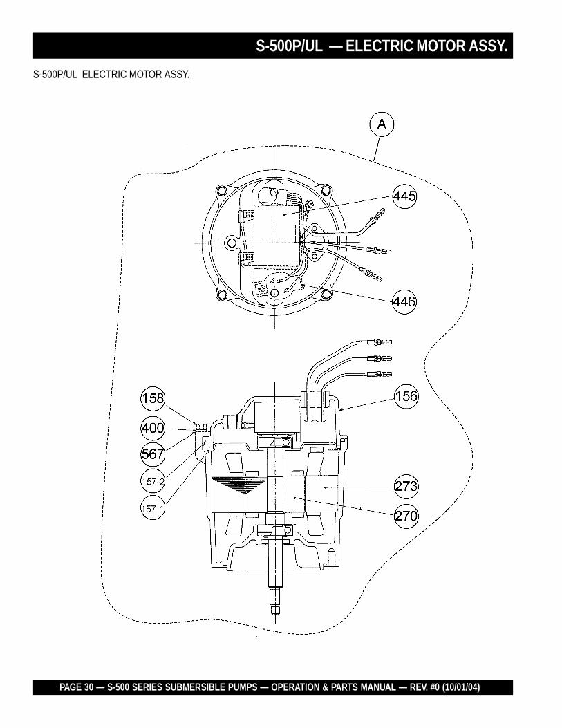
S-500P/UL ELECTRIC MOTOR ASSY.

S-500 SERIES SUBMERSIBLE PUMPS — OPERATION & PARTS MANUAL — REV. #0 (10/01/04) — PAGE 31
S-500P/UL ELECTRIC MOTOR ASSY.
NO PART NO PART NAME QTY. REMARK156* 020S500UL156 MOTOR HEAD COVER 1157-1* 020S500UL1571 HEAD COVER PACKING A 1157-2* 020S500UL1572 HEAD COVER PACKING B 1158* 020S500UL158 BOLT 4270* 020S500UL270 MOTOR ROTOR 1273* 020S500UL273 MOTOR STATOR 1400* 020S500UL400 SPRING WASHER 4445* 020S500UL445 CAPACITOR 1446* 020S500UL446 AUTO-CUT (PROTECTOR) 1567* 020S500UL567 WASHER 4A 020S500UL119 MOTOR ASSEMBLY ..................... 1 .................... INCLUDES ITEMS W/*
S-500P/UL — ELECTRIC MOTOR ASSY.

PAGE 32 — S-500 SERIES SUBMERSIBLE PUMPS — OPERATION & PARTS MANUAL — REV. #0 (10/01/04)
S-500CE — ELECTRIC MOTOR ASSY.
S-500CE ELECTRIC MOTOR ASSY.

S-500 SERIES SUBMERSIBLE PUMPS — OPERATION & PARTS MANUAL — REV. #0 (10/01/04) — PAGE 33
S-500CE — ELECTRIC MOTOR ASSY.
S-500CE ELECTRIC MOTOR ASSY.
NO PART NO PART NAME QTY. REMARK156* 020S500UL156 MOTOR HEAD COVER 1157-1* 020S500CE1571 HEAD COVER PACKING A 1157-2* 020S500CE1572 HEAD COVER PACKING B 1158* 020S500UL158 BOLT 4270* 020S500UL270 MOTOR ROTOR 1273* 020S500CE273 MOTOR STATOR 1400* 020S500UL400 SPRING WASHER 4445* 020S500CE445 CAPACITOR 1446* 020S500CE446 AUTO-CUT (PROTECTOR) 1567* 020S500UL567 WASHER 4A 020S500CE119 MOTOR ASSEMBLY ..................... 1 .................... INCLUDES ITEMS W/*

PAGE 34 — S-500 SERIES SUBMERSIBLE PUMPS — OPERATION & PARTS MANUAL — REV. #0 (10/01/04)
Effective: October 1, 2002 TERMS AND CONDITIONS OF SALE — PARTS
PAYMENT TERMS
Terms of payment for parts are net 10 days.
FREIGHT POLICY
All parts orders will be shipped collect orprepaid with the charges added to the invoice.All shipments are F.O.B. point of origin.Multiquip’s responsibility ceases when a signedmanifest has been obtained from the carrier,and any claim for shortage or damage must besettled between the consignee and the carrier.
MINIMUM ORDER
The minimum charge for orders from Mul-tiquip is $15.00 net. Customers will be askedfor instructions regarding handling of ordersnot meeting this requirement.
RETURNED GOODS POLICY
Return shipments will be accepted and creditwill be allowed, subject to the following provi-sions:
1. A Returned Material Authorization mustbe approved by Multiquip prior to ship-ment.
2. To obtain a Return Material Authorization,a list must be provided to Multiquip PartsSales that defines item numbers, quanti-ties, and descriptions of the items to bereturned.
a. The parts numbers and descriptionsmust match the current parts pricelist.
b. The list must be typed or computergenerated.
c. The list must state the reason(s) forthe return.
d. The list must reference the salesorder(s) or invoice(s) under which theitems were originally purchased.
e. The list must include the name andphone number of the person request-ing the RMA.
3. A copy of the Return Material Authoriza-tion must accompany the return shipment.
4. Freight is at the sender’s expense. Allparts must be returned freight prepaid toMultiquip’s designated receiving point.
5. Parts must be in new and resalable con-dition, in the original Multiquip package (ifany), and with Multiquip part numbersclearly marked.
6. The following items are not returnable:
a. Obsolete parts. (If an item is in theprice book and shows as being re-placed by another item, it is obsolete.)
b. Any parts with a limited shelf life(such as gaskets, seals, “O” rings,and other rubber parts) that were pur-chased more than six months prior tothe return date.
c. Any line item with an extended dealernet price of less than $5.00.
d. Special order items.
e. Electrical components.
f. Paint, chemicals, and lubricants.
g. Decals and paper products.
h. Items purchased in kits.
7. The sender will be notified of any materialreceived that is not acceptable.
8. Such material will be held for five workingdays from notification, pending instruc-tions. If a reply is not received within fivedays, the material will be returned to thesender at his expense.
9. Credit on returned parts will be issued atdealer net price at time of the originalpurchase, less a 15% restocking charge.
10. In cases where an item is accepted, forwhich the original purchase documentcan not be determined, the price will bebased on the list price that was effectivetwelve months prior to the RMA date.
11. Credit issued will be applied to futurepurchases only.
PRICING AND REBATES
Prices are subject to change without priornotice. Price changes are effective on a spe-cific date and all orders received on or after thatdate will be billed at the revised price. Rebatesfor price declines and added charges for priceincreases will not be made for stock on handat the time of any price change.
Multiquip reserves the right to quote and selldirect to Government agencies, and to OriginalEquipment Manufacturer accounts who useour products as integral parts of their ownproducts.
SPECIAL EXPEDITING SERVICE
A $35.00 surcharge will be added to the invoicefor special handling including bus shipments,insured parcel post or in cases where Multiquipmust personally deliver the parts to the carrier.
LIMITATIONS OF SELLER’S LIABILITY
Multiquip shall not be liable hereunder fordamages in excess of the purchase price of theitem with respect to which damages areclaimed, and in no event shall Multiquip beliable for loss of profit or good will or for anyother special, consequential or incidental dam-ages.
LIMITATION OF WARRANTIES
No warranties, express or implied, are madein connection with the sale of parts or tradeaccessories nor as to any engine not manufac-tured by Multiquip. Such warranties made inconnection with the sale of new, complete unitsare made exclusively by a statement of war-ranty packaged with such units, and Multiquipneither assumes nor authorizes any person toassume for it any other obligation or liabilitywhatever in connection with the sale of itsproducts. Apart from such written statement ofwarranty, there are no warranties, express,implied or statutory, which extend beyond thedescription of the products on the face hereof.

S-500 SERIES SUBMERSIBLE PUMPS — OPERATION & PARTS MANUAL — REV. #0 (10/01/04) — PAGE 35
NOTE PAGE

OPERATION AND PARTS MANUAL
MULTIQUIP INC.18910 WILMINGTON AVE.CARSON, CALIFORNIA 90746800-421-1244 • 310-537-3700FAX: 310-537-3927E-mail:[email protected]:multiquip.com
Your Local Dealer is:
HERE'S HOW TO GET HELPPLEASE HAVE THE MODEL AND SERIAL
NUMBER ON-HAND WHEN CALLINGMULTIQUIP CORPORATE OFFICE18910 Wilmington Ave. 800-421-1244Carson, CA 90746 FAX: 310-537-3927Email: [email protected]: www.multiquip.com
PARTS DEPARTMENT800-427-1244 FAX: 800-672-7877310-537-3700 FAX: 310-637-3284
MAYCO PARTS800-306-2926 FAX: 800-672-7877310-537-3700 FAX: 310-637-3284
SERVICE DEPARTMENT800-421-1244 FAX: 310-537-4259310-537-3700
TECHNICAL ASSISTANCE800-478-1244 FAX: 310-631-5032
WARRANTY DEPARTMENT800-421-1244, EXT. 279 FAX: 310-537-1173310-537-3700, EXT. 279