subscale flight testing of a generic fighter aircraft …€¦ · subscale flight testing of a...
TRANSCRIPT
SUBSCALE FLIGHT TESTING OF A GENERIC FIGHTERAIRCRAFT
David Lundström* , Alejandro Sobron* , Petter Krus* , Christopher Jouannet** ,Roberto Gil Annes da Silva***
*Linköping University, Linköping, Sweden*Saab AB, Sweden
***Instituto Tecnológico de Aeronáutica, São José dos Campos, Brazil
Keywords: subscale, free flight test, demonstrator, data acquisition
Abstract
Recent technological advances in mechatronicsenhance the possibilities of utilizing subscaleflight testing as a tool in the development of air-craft. This paper reports the current status ofa joint Swedish-Brazilian research project aim-ing at exploring these possibilities. A 13% scalefighter aircraft is used as a test bench for develop-ing methods and procedures for data acquisition.The aircraft is equipped with an instrumentationsystem assembled from off the shelf componentsas well as open source hardware and software.
1 Introduction
Since the birth of aviation, downscaled modelshave played an important role in aircraft devel-opment. Initially, simple free-flying uncontrolledmodels were used to understand the physics offlight. It was not long until these models were putin wind tunnels, allowing easier quantification ofcharacteristics, and it has since then remainedthe primary tool for aerodynamic studies. Nev-ertheless, the high operational cost of wind tun-nels and the increase of available computationalpower are making engineers rely increasingly onsimulations. However, simulations can be hard toverify, especially when applied to unconventionaland unproven concepts. Nowadays, with the newcapabilities of modern electronics, the interest infree-flying subscale models is rising again in theaeronautical community. With modern data ac-quisition tools and remote control (R/C) systems,
subscale flight testing can provide aerodynamicinformation in a way similar to a wind tunnel.And more interestingly, it can be used for identi-fication of flight dynamical characteristics duringearly stages of design, becoming a valuable in-put for risk reduction and for the design of flightcontrol systems. This paper describes an ongoingresearch program, MSDEMO, in which the pos-sibilities of subscale flight testing are explored.
1.1 Subscale Flight Testing
Testing of a scaled model in free-flight, equippedwith some form of data acquisition system, isgenerally referred to as subscale flight testing(SFT). NASA is in many ways the pioneer ofusing subscale models in aircraft research. Agood historic summary is given by Chambers [1].Free-flying models have been particularly usedfor dangerous tests, such as high angle-of-attackflight or to study departure modes. Spin mod-els for updraft wind tunnels have been a standardpractice since the 1940s, but free-flight mod-els have also been built for conventional windtunnels such as the NASA Langley Free-FlightFacility [2]. Spin testing is also often carriedout using remotely controlled unpowered modelsdropped from helicopters. In Sweden, this wasused during the Saab Viggen test program [3].More recent examples of how drop models havebeen used are the X-31 program [4] and BoeingF/A-18E/F [5]. Subscale drop models have alsobeen used for studies of space vehicles such asthe Lockheed Martin X-38 and Japanese HOPE-
1
LUNDSTRÖM D, SOBRON A, JOUANNET C, KRUS P, SILVA RGA
X [6].More advanced demonstrators are often pow-
ered by their own internal propulsion systems.Some examples are the Rockwell HiMAT [7],the NASA-funded McDonnell Douglas X-36 [8],the Saab SHARC UAV [9], the NASA X-43A-LS [10], the proposed Gulfstream Quiet Super-sonic Jet [11], and the BAE Systems UAV tech-nology research program FLAVIIR [12]. In allthese cases the configurations are highly uncon-ventional and there is thus a desire to demon-strate their feasibility without the cost or risk of amanned, full-scale vehicle.
Recently, the use of subscale flight testing hasbeen extended to civil aircraft, as in the NASAAirSTAR research program [13], in which scaledmodels are used to explore an extended flight en-velope for a civil transport aircraft.
Regarding blended wing body concepts, theX-48 program from Boeing and NASA has beenusing a scaled model to demonstrate the conceptand obtain more data without going to full-scale[14]. An example of a pure research project withpartners from both university and industry is theNACRE Innovative Evaluation Platform (IEP),in which a modular, dynamically-scaled aircraftis built to study environmental and safety issues[15].
2 MSDEMO Project
MSDEMO is a research project that investigatesmethods for subscale flight testing and demon-stration, which also includes a research collab-oration with the Brazilian universities InstitutoTecnológico de Aeronáutica (ITA) and Univer-sity of São Paulo (USP). It is a subset of alarger initiative regarding Future Aircraft Designand Demonstration (FADEMO). The MSDEMOproject as a whole is focusing on the followingtopics:
• Possibilities and limitations of subscaledemonstrators in aircraft development,
• Dynamic scaling for development of con-trol laws for unconventional configura-tions,
• Scaling methods depending on the issues tobe addressed and the associated cost,
• Flight testing methods, repeatability anduncertainty issues,
• Implementations of an efficient avionicsystem for flight control and data logging.
A secondary objective of this project is topromote and facilitate research collaboration be-tween Sweden and Brazil in the aeronauticalfield. This type of project is envisaged to besuitable in that sense, since the valuable datasets generated can also be used by other researchgroups not directly involved in this project. Theycan then also give feedback into the project,which can in this way form an enabler for furthercollaborative projects.
The MSDEMO project runs with independentfinancing on both sides. The Swedish side of theproject, is funded by the National Program forAeronautics Research with a budget of approx-imately 300,000 Euro for a two-year duration,with a plan for continuation.
The project has an strong focus on minimum-cost test techniques using as much off-the-shelfequipment as possible. There is an ongoing tech-nological revolution in electronics and mecha-tronics. A good example is the Arduino andRaspberry Pi development communities, makingit simpler than ever to fuse electronics and hard-ware. The hobbyist R/C and "drone" commu-nities are another example where sophisticatedelectronics have raised the bar significantly in re-cent years. Components such as miniature gasturbine engines, powerful and precise actuators,robust and redundant data links, telemetry sys-tems, and other advanced equipment are availableat low cost. The open source community of au-topilot systems such as Paparazzi [16], ArduPi-lot/APM [17] or PX4 [18], is yet an example ofthis revolution. MSDEMO intends to utilize thistechnological revolution to bring down the costand maximize the technological benefit of sub-scale flight testing.
The project makes use of various platforms ofdifferent size and complexity. At Linköping Uni-versity, the main research platform is an already
2
SUBSCALE FLIGHT TESTING OF A GENERIC FIGHTER AIRCRAFT
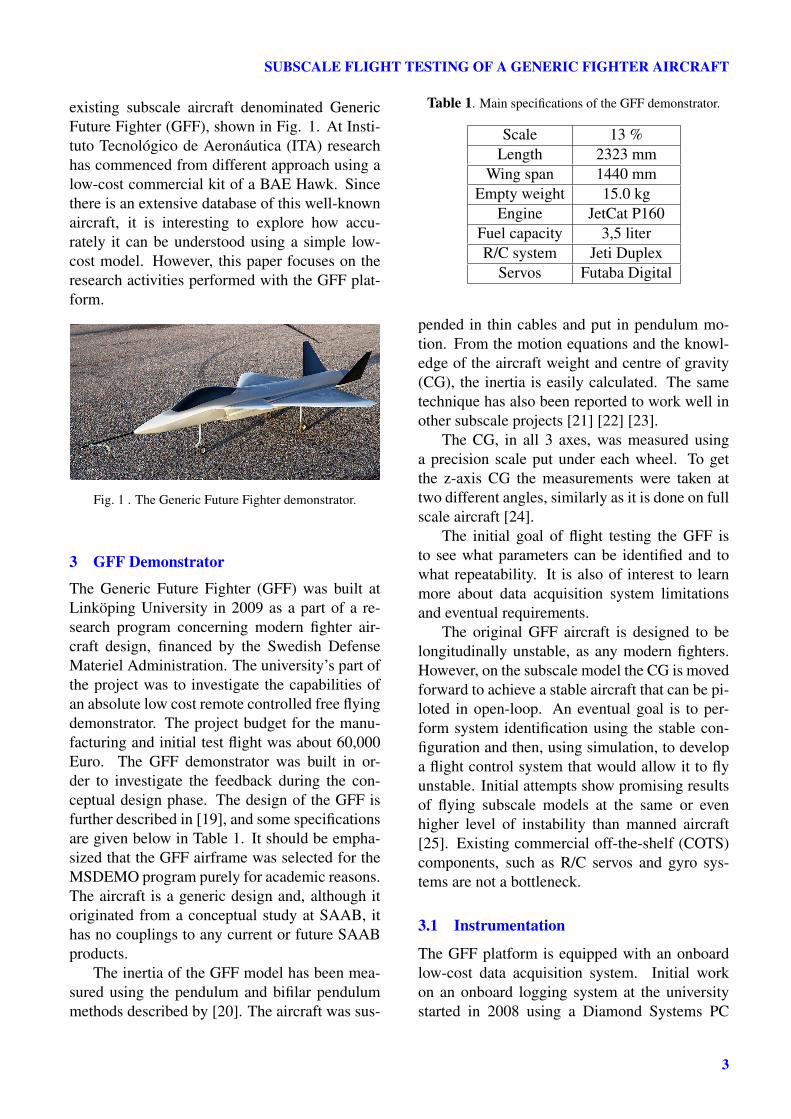
existing subscale aircraft denominated GenericFuture Fighter (GFF), shown in Fig. 1. At Insti-tuto Tecnológico de Aeronáutica (ITA) researchhas commenced from different approach using alow-cost commercial kit of a BAE Hawk. Sincethere is an extensive database of this well-knownaircraft, it is interesting to explore how accu-rately it can be understood using a simple low-cost model. However, this paper focuses on theresearch activities performed with the GFF plat-form.
Fig. 1 . The Generic Future Fighter demonstrator.
3 GFF Demonstrator
The Generic Future Fighter (GFF) was built atLinköping University in 2009 as a part of a re-search program concerning modern fighter air-craft design, financed by the Swedish DefenseMateriel Administration. The university’s part ofthe project was to investigate the capabilities ofan absolute low cost remote controlled free flyingdemonstrator. The project budget for the manu-facturing and initial test flight was about 60,000Euro. The GFF demonstrator was built in or-der to investigate the feedback during the con-ceptual design phase. The design of the GFF isfurther described in [19], and some specificationsare given below in Table 1. It should be empha-sized that the GFF airframe was selected for theMSDEMO program purely for academic reasons.The aircraft is a generic design and, although itoriginated from a conceptual study at SAAB, ithas no couplings to any current or future SAABproducts.
The inertia of the GFF model has been mea-sured using the pendulum and bifilar pendulummethods described by [20]. The aircraft was sus-
Table 1. Main specifications of the GFF demonstrator.
Scale 13 %Length 2323 mm
Wing span 1440 mmEmpty weight 15.0 kg
Engine JetCat P160Fuel capacity 3,5 literR/C system Jeti Duplex
Servos Futaba Digital
pended in thin cables and put in pendulum mo-tion. From the motion equations and the knowl-edge of the aircraft weight and centre of gravity(CG), the inertia is easily calculated. The sametechnique has also been reported to work well inother subscale projects [21] [22] [23].
The CG, in all 3 axes, was measured usinga precision scale put under each wheel. To getthe z-axis CG the measurements were taken attwo different angles, similarly as it is done on fullscale aircraft [24].
The initial goal of flight testing the GFF isto see what parameters can be identified and towhat repeatability. It is also of interest to learnmore about data acquisition system limitationsand eventual requirements.
The original GFF aircraft is designed to belongitudinally unstable, as any modern fighters.However, on the subscale model the CG is movedforward to achieve a stable aircraft that can be pi-loted in open-loop. An eventual goal is to per-form system identification using the stable con-figuration and then, using simulation, to developa flight control system that would allow it to flyunstable. Initial attempts show promising resultsof flying subscale models at the same or evenhigher level of instability than manned aircraft[25]. Existing commercial off-the-shelf (COTS)components, such as R/C servos and gyro sys-tems are not a bottleneck.
3.1 Instrumentation
The GFF platform is equipped with an onboardlow-cost data acquisition system. Initial workon an onboard logging system at the universitystarted in 2008 using a Diamond Systems PC
3
LUNDSTRÖM D, SOBRON A, JOUANNET C, KRUS P, SILVA RGA
board “Athena” with a Pentium III class proces-sor running a streamlined Linux kernel as operat-ing system [26]. The resulting system was how-ever slightly oversized for some platforms, and itwas affected by timing problems caused by thenon-real-time operating system.
Taking into consideration the experiencegained it was decided to develop a new systembased on microcontrollers without any operatingsystem. This reduces the hardware to an abso-lute minimum and therefore the cost, size andpower consumption. The new system, based ona 32-bit Atmel microcontroller, reached a fairlymature state as described in [27]. Everything,including the ground-station and data-links, wasprogrammed from scratch. It was therefore la-bor intensive to work with, and it also presenteda limited number of input and output channels.Although it proved capable, during the initialtest campaign of the GFF this solution was putaside in favor of a more compact, modular sys-tem partially based on low-cost COTS compo-nents. As explained in [25], the new generationof hobbyist-type open-source flight controllersbased on 32 bit microprocessors offer excellentdata processing capabilities and are able to logmultiple channels at sample rates that seem suffi-cient for flight-dynamics system identification.
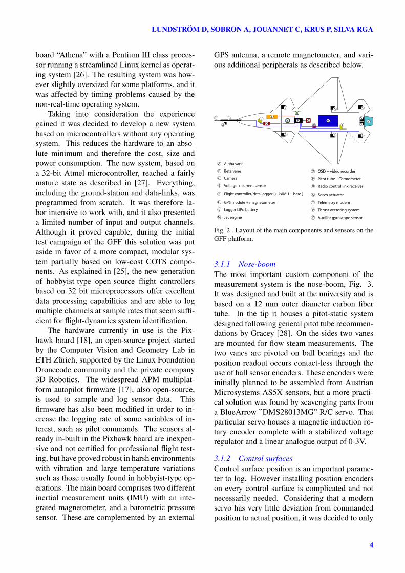
The hardware currently in use is the Pix-hawk board [18], an open-source project startedby the Computer Vision and Geometry Lab inETH Zürich, supported by the Linux FoundationDronecode community and the private company3D Robotics. The widespread APM multiplat-form autopilot firmware [17], also open-source,is used to sample and log sensor data. Thisfirmware has also been modified in order to in-crease the logging rate of some variables of in-terest, such as pilot commands. The sensors al-ready in-built in the Pixhawk board are inexpen-sive and not certified for professional flight test-ing, but have proved robust in harsh environmentswith vibration and large temperature variationssuch as those usually found in hobbyist-type op-erations. The main board comprises two differentinertial measurement units (IMU) with an inte-grated magnetometer, and a barometric pressuresensor. These are complemented by an external
GPS antenna, a remote magnetometer, and vari-ous additional peripherals as described below.
GF
R
E T
P
A
A
F
G
B
S
R
T
E
M
Alpha vane
Beta vane
Voltage + current sensor
Flight controller/data logger (+ 2xIMU + baro.)
GPS module + magnetometer
Jet engine
Radio control link receiver
Servo actuator
Telemetry modem
B
OC
LY M
S
C Camera
L Logger LiPo battery
O OSD + video recorder
P Pitot tube + Termometer
Y Auxiliar gyroscope sensor
V
V Thrust vectoring system
S
S
S S
S
S
S
Fig. 2 . Layout of the main components and sensors on theGFF platform.
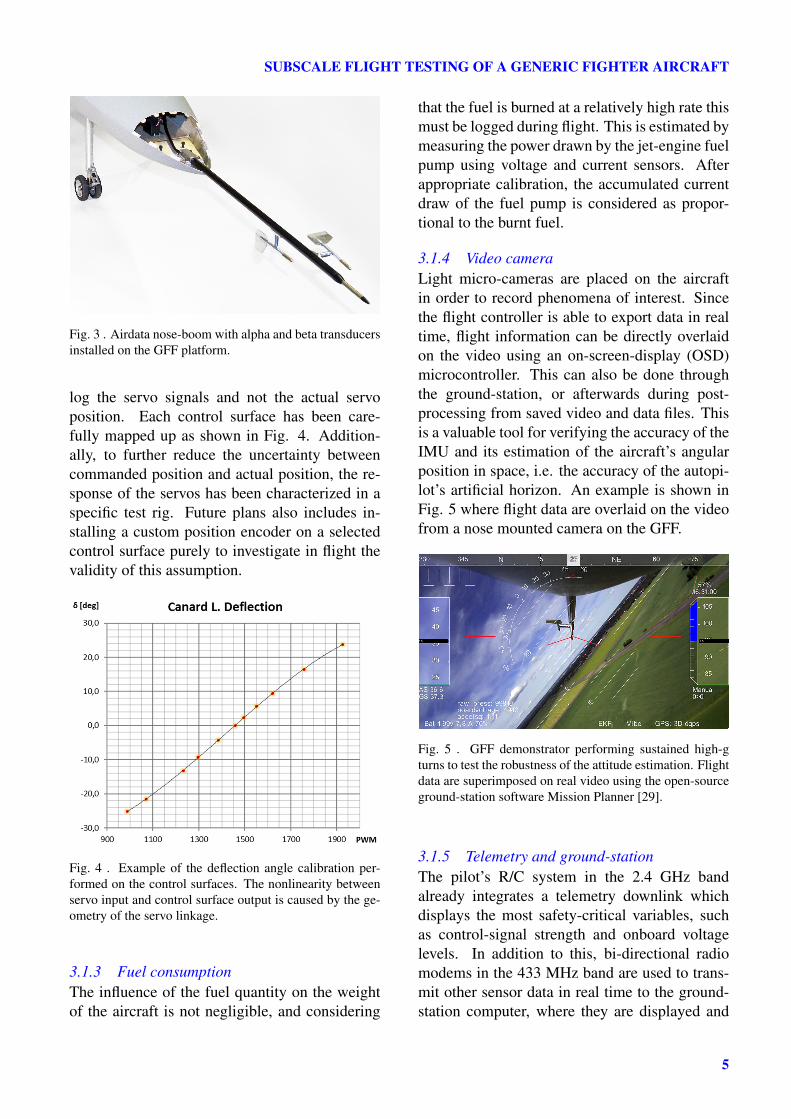
3.1.1 Nose-boomThe most important custom component of themeasurement system is the nose-boom, Fig. 3.It was designed and built at the university and isbased on a 12 mm outer diameter carbon fibertube. In the tip it houses a pitot-static systemdesigned following general pitot tube recommen-dations by Gracey [28]. On the sides two vanesare mounted for flow steam measurements. Thetwo vanes are pivoted on ball bearings and theposition readout occurs contact-less through theuse of hall sensor encoders. These encoders wereinitially planned to be assembled from AustrianMicrosystems AS5X sensors, but a more practi-cal solution was found by scavenging parts froma BlueArrow ”DMS28013MG” R/C servo. Thatparticular servo houses a magnetic induction ro-tary encoder complete with a stabilized voltageregulator and a linear analogue output of 0-3V.
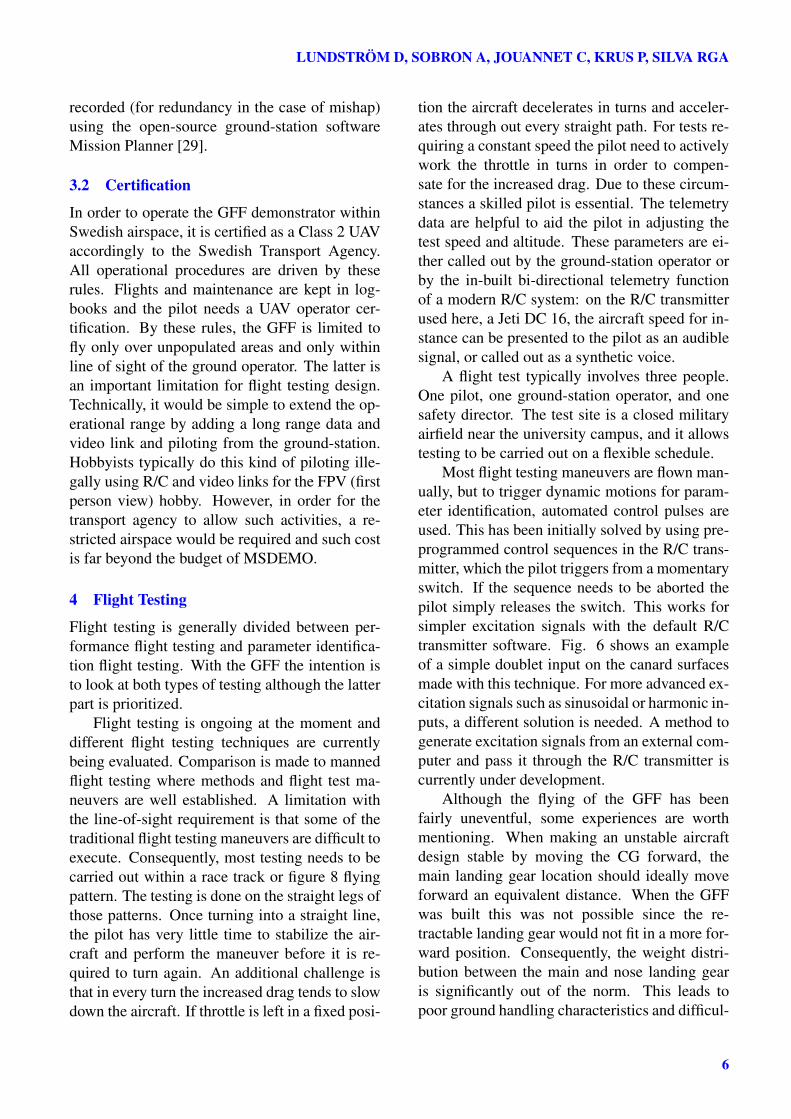
3.1.2 Control surfacesControl surface position is an important parame-ter to log. However installing position encoderson every control surface is complicated and notnecessarily needed. Considering that a modernservo has very little deviation from commandedposition to actual position, it was decided to only
4
SUBSCALE FLIGHT TESTING OF A GENERIC FIGHTER AIRCRAFT
Fig. 3 . Airdata nose-boom with alpha and beta transducersinstalled on the GFF platform.
log the servo signals and not the actual servoposition. Each control surface has been care-fully mapped up as shown in Fig. 4. Addition-ally, to further reduce the uncertainty betweencommanded position and actual position, the re-sponse of the servos has been characterized in aspecific test rig. Future plans also includes in-stalling a custom position encoder on a selectedcontrol surface purely to investigate in flight thevalidity of this assumption.
Fig. 4 . Example of the deflection angle calibration per-formed on the control surfaces. The nonlinearity betweenservo input and control surface output is caused by the ge-ometry of the servo linkage.
3.1.3 Fuel consumptionThe influence of the fuel quantity on the weightof the aircraft is not negligible, and considering
that the fuel is burned at a relatively high rate thismust be logged during flight. This is estimated bymeasuring the power drawn by the jet-engine fuelpump using voltage and current sensors. Afterappropriate calibration, the accumulated currentdraw of the fuel pump is considered as propor-tional to the burnt fuel.
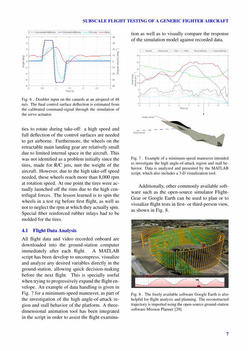
3.1.4 Video cameraLight micro-cameras are placed on the aircraftin order to record phenomena of interest. Sincethe flight controller is able to export data in realtime, flight information can be directly overlaidon the video using an on-screen-display (OSD)microcontroller. This can also be done throughthe ground-station, or afterwards during post-processing from saved video and data files. Thisis a valuable tool for verifying the accuracy of theIMU and its estimation of the aircraft’s angularposition in space, i.e. the accuracy of the autopi-lot’s artificial horizon. An example is shown inFig. 5 where flight data are overlaid on the videofrom a nose mounted camera on the GFF.
Fig. 5 . GFF demonstrator performing sustained high-gturns to test the robustness of the attitude estimation. Flightdata are superimposed on real video using the open-sourceground-station software Mission Planner [29].
3.1.5 Telemetry and ground-stationThe pilot’s R/C system in the 2.4 GHz bandalready integrates a telemetry downlink whichdisplays the most safety-critical variables, suchas control-signal strength and onboard voltagelevels. In addition to this, bi-directional radiomodems in the 433 MHz band are used to trans-mit other sensor data in real time to the ground-station computer, where they are displayed and
5
LUNDSTRÖM D, SOBRON A, JOUANNET C, KRUS P, SILVA RGA
recorded (for redundancy in the case of mishap)using the open-source ground-station softwareMission Planner [29].
3.2 Certification
In order to operate the GFF demonstrator withinSwedish airspace, it is certified as a Class 2 UAVaccordingly to the Swedish Transport Agency.All operational procedures are driven by theserules. Flights and maintenance are kept in log-books and the pilot needs a UAV operator cer-tification. By these rules, the GFF is limited tofly only over unpopulated areas and only withinline of sight of the ground operator. The latter isan important limitation for flight testing design.Technically, it would be simple to extend the op-erational range by adding a long range data andvideo link and piloting from the ground-station.Hobbyists typically do this kind of piloting ille-gally using R/C and video links for the FPV (firstperson view) hobby. However, in order for thetransport agency to allow such activities, a re-stricted airspace would be required and such costis far beyond the budget of MSDEMO.
4 Flight Testing
Flight testing is generally divided between per-formance flight testing and parameter identifica-tion flight testing. With the GFF the intention isto look at both types of testing although the latterpart is prioritized.
Flight testing is ongoing at the moment anddifferent flight testing techniques are currentlybeing evaluated. Comparison is made to mannedflight testing where methods and flight test ma-neuvers are well established. A limitation withthe line-of-sight requirement is that some of thetraditional flight testing maneuvers are difficult toexecute. Consequently, most testing needs to becarried out within a race track or figure 8 flyingpattern. The testing is done on the straight legs ofthose patterns. Once turning into a straight line,the pilot has very little time to stabilize the air-craft and perform the maneuver before it is re-quired to turn again. An additional challenge isthat in every turn the increased drag tends to slowdown the aircraft. If throttle is left in a fixed posi-
tion the aircraft decelerates in turns and acceler-ates through out every straight path. For tests re-quiring a constant speed the pilot need to activelywork the throttle in turns in order to compen-sate for the increased drag. Due to these circum-stances a skilled pilot is essential. The telemetrydata are helpful to aid the pilot in adjusting thetest speed and altitude. These parameters are ei-ther called out by the ground-station operator orby the in-built bi-directional telemetry functionof a modern R/C system: on the R/C transmitterused here, a Jeti DC 16, the aircraft speed for in-stance can be presented to the pilot as an audiblesignal, or called out as a synthetic voice.
A flight test typically involves three people.One pilot, one ground-station operator, and onesafety director. The test site is a closed militaryairfield near the university campus, and it allowstesting to be carried out on a flexible schedule.
Most flight testing maneuvers are flown man-ually, but to trigger dynamic motions for param-eter identification, automated control pulses areused. This has been initially solved by using pre-programmed control sequences in the R/C trans-mitter, which the pilot triggers from a momentaryswitch. If the sequence needs to be aborted thepilot simply releases the switch. This works forsimpler excitation signals with the default R/Ctransmitter software. Fig. 6 shows an exampleof a simple doublet input on the canard surfacesmade with this technique. For more advanced ex-citation signals such as sinusoidal or harmonic in-puts, a different solution is needed. A method togenerate excitation signals from an external com-puter and pass it through the R/C transmitter iscurrently under development.
Although the flying of the GFF has beenfairly uneventful, some experiences are worthmentioning. When making an unstable aircraftdesign stable by moving the CG forward, themain landing gear location should ideally moveforward an equivalent distance. When the GFFwas built this was not possible since the re-tractable landing gear would not fit in a more for-ward position. Consequently, the weight distri-bution between the main and nose landing gearis significantly out of the norm. This leads topoor ground handling characteristics and difficul-
6
SUBSCALE FLIGHT TESTING OF A GENERIC FIGHTER AIRCRAFT
0 0.5 1 1.5 2 2.5 3Time [s]
-8
-6
-4
-2
0
2
4
6
8
Ang
le [d
eg]
Ang
ular
vel
ocity
[deg
-1]
Commanded de�ection Estimated de�ection Pitch rate Alpha
-40
-30
-20
-10
0
10
20
30
40
Fig. 6 . Doublet input on the canards at an airspeed of 48m/s. The final control surface deflection is estimated fromthe calibrated command-signal through the simulation ofthe servo actuator.
ties to rotate during take-off: a high speed andfull deflection of the control surfaces are neededto get airborne. Furthermore, the wheels on theretractable main landing gear are relatively smalldue to limited internal space in the aircraft. Thiswas not identified as a problem initially since thetires, made for R/C jets, met the weight of theaircraft. However, due to the high take-off speedneeded, these wheels reach more than 8,000 rpmat rotation speed. At one point the tires were ac-tually launched off the rims due to the high cen-trifugal forces. The lesson learned is to spin thewheels in a test rig before first flight, as well asnot to neglect the rpm at which they actually spin.Special fiber reinforced rubber inlays had to bemolded for the tires.
4.1 Flight Data Analysis
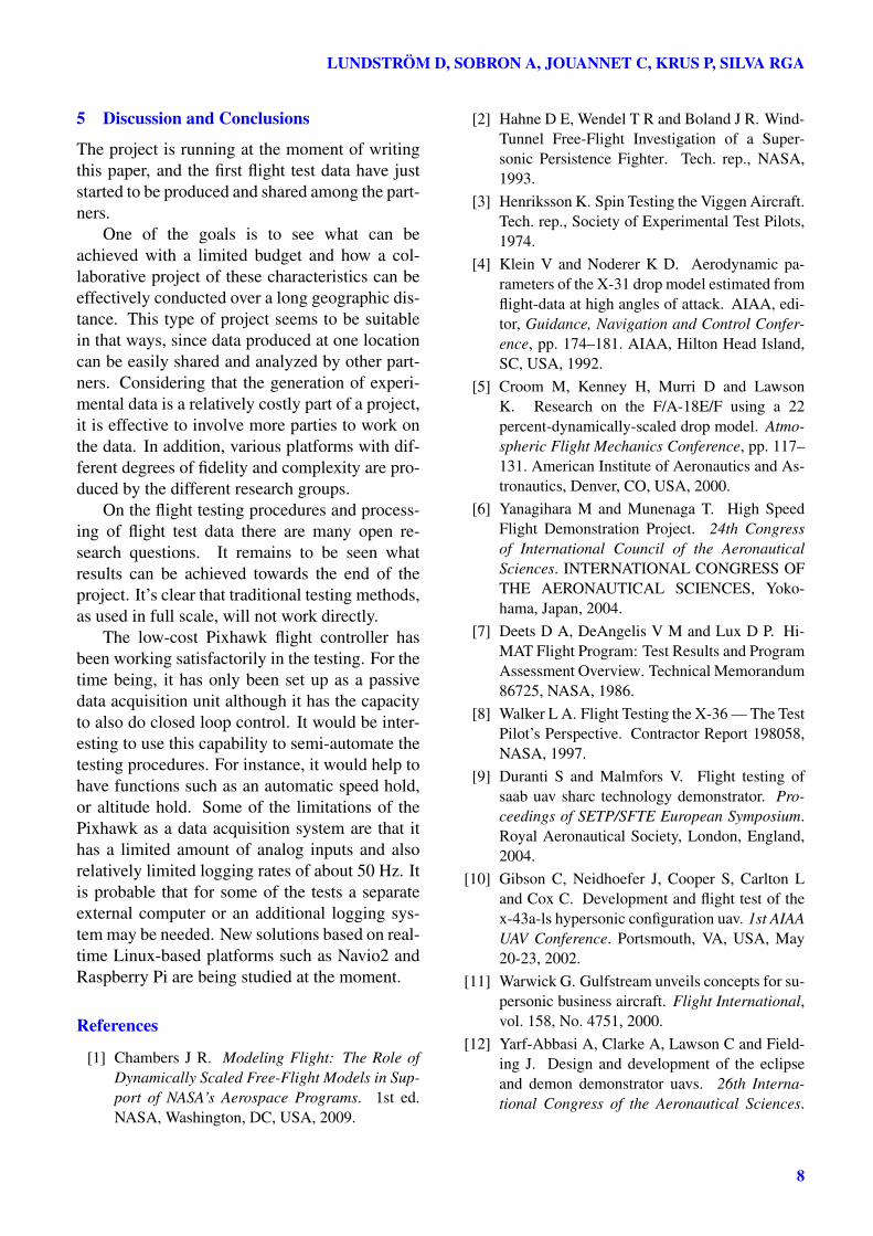
All flight data and video recorded onboard aredownloaded into the ground-station computerimmediately after each flight. A MATLABscript has been develop to uncompress, visualizeand analyze any desired variables directly in theground-station, allowing quick decision-makingbefore the next flight. This is specially usefulwhen trying to progressively expand the flight en-velope. An example of data handling is given inFig. 7 for a minimum-speed maneuver, as part ofthe investigation of the high angle-of-attack re-gion and stall behavior of the platform. A three-dimensional animation tool has been integratedin the script in order to assist the flight examina-
tion as well as to visually compare the responseof the simulation model against recorded data.
0 1 2 3 4 5 6 7 8 9
Time [s]
-5
0
5
10
15
20
25
30
Ang
le [d
eg]
Velo
city
[m s
-1]
Airspeed Vertical speed Pitch Alpha Elevon de�ection Canard de�ection
wind vector
body vector
Fig. 7 . Example of a minimum-speed maneuver intendedto investigate the high angle-of-attack region and stall be-havior. Data is analyzed and presented by the MATLABscript, which also includes a 3-D visualization tool.
Additionally, other commonly available soft-ware such as the open-source simulator Flight-Gear or Google Earth can be used to plan or tovisualize flight tests in first- or third-person view,as shown in Fig. 8.
Fig. 8 . The freely available software Google Earth is alsohelpful for flight analysis and planning. The reconstructedtrajectory is imported using the open-source ground-stationsoftware Mission Planner [29].
7
LUNDSTRÖM D, SOBRON A, JOUANNET C, KRUS P, SILVA RGA
5 Discussion and Conclusions
The project is running at the moment of writingthis paper, and the first flight test data have juststarted to be produced and shared among the part-ners.
One of the goals is to see what can beachieved with a limited budget and how a col-laborative project of these characteristics can beeffectively conducted over a long geographic dis-tance. This type of project seems to be suitablein that ways, since data produced at one locationcan be easily shared and analyzed by other part-ners. Considering that the generation of experi-mental data is a relatively costly part of a project,it is effective to involve more parties to work onthe data. In addition, various platforms with dif-ferent degrees of fidelity and complexity are pro-duced by the different research groups.
On the flight testing procedures and process-ing of flight test data there are many open re-search questions. It remains to be seen whatresults can be achieved towards the end of theproject. It’s clear that traditional testing methods,as used in full scale, will not work directly.
The low-cost Pixhawk flight controller hasbeen working satisfactorily in the testing. For thetime being, it has only been set up as a passivedata acquisition unit although it has the capacityto also do closed loop control. It would be inter-esting to use this capability to semi-automate thetesting procedures. For instance, it would help tohave functions such as an automatic speed hold,or altitude hold. Some of the limitations of thePixhawk as a data acquisition system are that ithas a limited amount of analog inputs and alsorelatively limited logging rates of about 50 Hz. Itis probable that for some of the tests a separateexternal computer or an additional logging sys-tem may be needed. New solutions based on real-time Linux-based platforms such as Navio2 andRaspberry Pi are being studied at the moment.
References
[1] Chambers J R. Modeling Flight: The Role ofDynamically Scaled Free-Flight Models in Sup-port of NASA’s Aerospace Programs. 1st ed.NASA, Washington, DC, USA, 2009.
[2] Hahne D E, Wendel T R and Boland J R. Wind-Tunnel Free-Flight Investigation of a Super-sonic Persistence Fighter. Tech. rep., NASA,1993.
[3] Henriksson K. Spin Testing the Viggen Aircraft.Tech. rep., Society of Experimental Test Pilots,1974.
[4] Klein V and Noderer K D. Aerodynamic pa-rameters of the X-31 drop model estimated fromflight-data at high angles of attack. AIAA, edi-tor, Guidance, Navigation and Control Confer-ence, pp. 174–181. AIAA, Hilton Head Island,SC, USA, 1992.
[5] Croom M, Kenney H, Murri D and LawsonK. Research on the F/A-18E/F using a 22percent-dynamically-scaled drop model. Atmo-spheric Flight Mechanics Conference, pp. 117–131. American Institute of Aeronautics and As-tronautics, Denver, CO, USA, 2000.
[6] Yanagihara M and Munenaga T. High SpeedFlight Demonstration Project. 24th Congressof International Council of the AeronauticalSciences. INTERNATIONAL CONGRESS OFTHE AERONAUTICAL SCIENCES, Yoko-hama, Japan, 2004.
[7] Deets D A, DeAngelis V M and Lux D P. Hi-MAT Flight Program: Test Results and ProgramAssessment Overview. Technical Memorandum86725, NASA, 1986.
[8] Walker L A. Flight Testing the X-36 — The TestPilot’s Perspective. Contractor Report 198058,NASA, 1997.
[9] Duranti S and Malmfors V. Flight testing ofsaab uav sharc technology demonstrator. Pro-ceedings of SETP/SFTE European Symposium.Royal Aeronautical Society, London, England,2004.
[10] Gibson C, Neidhoefer J, Cooper S, Carlton Land Cox C. Development and flight test of thex-43a-ls hypersonic configuration uav. 1st AIAAUAV Conference. Portsmouth, VA, USA, May20-23, 2002.
[11] Warwick G. Gulfstream unveils concepts for su-personic business aircraft. Flight International,vol. 158, No. 4751, 2000.
[12] Yarf-Abbasi A, Clarke A, Lawson C and Field-ing J. Design and development of the eclipseand demon demonstrator uavs. 26th Interna-tional Congress of the Aeronautical Sciences.
8
SUBSCALE FLIGHT TESTING OF A GENERIC FIGHTER AIRCRAFT
Anchorage, AK, USA, Sept. 2008.[13] Jordan T L, Foster J V, Bailey R M and Bel-
castro C M. AirSTAR: A UAV Platform forFlight Dynamics and Control System Testing.25th AIAA Aerodynamic Measurement Technol-ogy and Ground Testing Conference. AmericanInstitute of Aeronautics and Astronautics, SanFracisco, CA, USA, 2006.
[14] Risch T, Cosentino G, Regan C, Kisska Mand Princen N. X-48B Flight Test ProgressOverview. 47th AIAA Aerospace Sciences Meet-ing. Orlando, FL, USA, 2009.
[15] Schmollgruber P, Jentink H W and TuinstraM. Iep : a Multidisciplinary Flying Testbedfor New Aircraft Concepts. 27th InternationalCongress of the Aeronautical Sciences. Nice,France, 2010.
[16] École nationale de l’aviation civile and Pa-parazzi develpers community. Paparazziproject, open-source autopilot system, 2015.URL http://wiki.paparazziuav.org/
[17] Dronecode Project Inc a Linux Foundation Col-laborative Project. APM:Plane open-source au-topilot firmware, 2016.URL http://plane.ardupilot.com/
[18] Computer Vision and Geometry Lab at ETHZürich 3D Robotics Inc and PX4 developerscommunity. PX4/Pixhawk open-hardware au-topilot project, 2015.URL http://pixhawk.org/
[19] Amadori K, Jouannet C and Berry P. Develop-ment of a subscale flight testing platform for ageneric future fighter. 27th Congress of Inter-national Council of the Aeronautical Sciences.Nice, France, 2010.
[20] Miller M P. An accurate method of measuringthe moments of inertia of airplanes. Tech. Rep.NACA-TN-351, NACA, 1930.
[21] McClelland W A. Inertia Measurement and Dy-namic Stability Analysis of a Radio-ControlledJoined-Wing Aircraft. Thesis, Department ofAeronautical Engineering, Air Force Institute ofTechnology, 2006.
[22] Bussamra F L d S, Montestruque Vilchez M Cand Santos J C. Experimental Determination ofUnmanned Aircraft Inertial Properties. Brazil-ian Symposium on Aerospace Eng. & Applica-tions. Campos, SP, Brazil, 2009.
[23] Seanor B A. Flight testing of a remotely piloted
vehicle for aircraft parameter estimation pur-poses. Ph.D. thesis, West Virginia University,2002.
[24] Ward D T, Strganac T W and Rob N. Introduc-tion to Flight Test Engineering, Vol. 1. 3rd ed.Kendall Hunt Publishing, 2006.
[25] Sobron A, Lundström D, Staack I and Krus P.Design and Testing of a Low-Cost Flight Con-trol and Data Acquisition System for UnstableSubscale Aircraft. 30th Congress of the Inter-national Council of the Aeronautical Sciences.Daejeon, South Korea, 2016.
[26] Lundström D and Amadori K. Raven – a Sub-scale Radio Controlled Business Jet Demonstra-tor. 26th International Congress of the Aeronau-tical Sciences. Anchorage, AK, USA, 2008.
[27] Staack I and Lundström D. Subscale FlightTesting at Linköping University. 27th Congressof International Council of the AeronauticalSciences. Nice, France, 2010.
[28] Gracey W. Measurement of Aircraft Speed andAltitude. Reference Publication 1046, NASA,1980.
[29] Oborne M and Dronecode Project Inc. Mis-sion Planner open-source ground station soft-ware, Version 1.3.37, 2016.URL http://ardupilot.org/planner/
Contact Author Email [email protected]
Copyright StatementThe authors confirm that they, and/or their companyor organization, hold copyright on all of the origi-nal material included in this paper. The authors alsoconfirm that they have obtained permission, from thecopyright holder of any third party material includedin this paper, to publish it as part of their paper. Theauthors confirm that they give permission, or have ob-tained permission from the copyright holder of thispaper, for the publication and distribution of this pa-per as part of the ICAS proceedings or as individualoff-prints from the proceedings.
9