practical application of a subscale transport aircraft … · practical application of a subscale...
TRANSCRIPT
American Institute of Aeronautics and Astronautics
1
Practical Application of a Subscale Transport Aircraft for Flight Research in Control Upset and Failure Conditions
Cunningham, Kevin*, Foster, John V., †, Morelli, Eugene A. ‡, and Murch, Austin M. § NASA Langley Research Center, Hampton, VA 23681-2199
Over the past decade, the goal of reducing the fatal accident rate of large transport aircraft has resulted in research aimed at the problem of aircraft loss-of-control. Starting in 1999, the NASA Aviation Safety Program initiated research that included vehicle dynamics modeling, system health monitoring, and reconfigurable control systems focused on flight regimes beyond the normal flight envelope. In recent years, there has been an increased emphasis on adaptive control technologies for recovery from control upsets or failures including damage scenarios. As part of these efforts, NASA has developed the Airborne Subscale Transport Aircraft Research (AirSTAR) flight facility to allow flight research and validation, and system testing for flight regimes that are considered too risky for full-scale manned transport airplane testing. The AirSTAR facility utilizes dynamically-scaled vehicles that enable the application of subscale flight test results to full scale vehicles. This paper describes the modeling and simulation approach used for AirSTAR vehicles that supports the goals of efficient, low-cost and safe flight research in abnormal flight conditions. Modeling of aerodynamics, controls, and propulsion will be discussed as well as the application of simulation to flight control system development, test planning, risk mitigation, and flight research.
Nomenclature AirSTAR = Airborne Subscale Transport Aircraft Research AvSP = Aviation Safety Program CONOPS = concept of operations FCS = flight control system GPS = global positioning system HITL = hardware-in-the-loop IMU = inertial measurement unit INS = inertial navigation system IRAC = Integrated Resilient Aircraft Controls IVHM = Integrated Vehicle Health Management LOC = loss of control M = Mach number MOS = mobile operation station NASA = National Aeronautics and Space Administration UAV = unmanned aerial vehicle x y za ,a ,a = body-axis translational accelerations, ft/sec2
b = wing span, ft c = wing mean aerodynamic chord, ft Ix, Iy, Iz, Ixz = moments of inertia p, q, r = body-axis roll, pitch, and yaw rates, rad/sec
* Research Engineer, Flight Dynamics Branch, MS 308, AIAA Senior Member. † Research Engineer, Flight Dynamics Branch, MS 308, AIAA Associate Fellow. ‡ Research Engineer, Dynamic Systems and Control Branch, MS 308, AIAA Associate Fellow. § Research Engineer, Flight Dynamics Branch, MS 308, AIAA Member.
https://ntrs.nasa.gov/search.jsp?R=20080034480 2018-08-16T13:24:14+00:00Z
American Institute of Aeronautics and Astronautics
2
q = dynamic pressure, lbf/ft2 S = wing reference area, ft2 V = airspeed, ft/sec ! = angle of attack, deg ! = sideslip angle, deg
e a r f, , ,! ! ! ! = elevator, aileron, rudder, and trailing-edge flap deflections, deg
superscripts & = time derivative
subscripts cg = center of gravity location o = base term ref = reference location
I. Introduction Loss of control (LOC) has been one of the leading contributors to the fatal accident rate of large commercial
transport airplanes. These types of accidents are of great concern because they are usually catastrophic, involving loss of aircraft and lives1. LOC accidents are complex in that they typically have many causal factors and precursors, and they are difficult to analyze because they often involve excursions beyond the normal flight envelope. For example, LOC accidents have exhibited post-stall angles of attack and/or steep pitch and bank attitudes, which can make recovery to normal flight extremely difficult.
Research has been conducted over the past decade to better understand the complex flight dynamics characteristics of large transports in abnormal flight conditions2-5. Wind-tunnel experiments have documented highly non-linear and degraded aerodynamic stability and control characteristics that occur at high angles of attack or with airframe damage. Based on these experimental data, aerodynamic models have been developed and used in piloted simulations to demonstrate flight characteristics in LOC conditions including stalls, departures, and control system failures.
One of the emerging solutions to the LOC problem is the use of adaptive control technologies that can recognize potentially dangerous flight conditions, reconfigure the control system to optimize controllability, and enable aircraft recovery from scenarios that could otherwise result in an accident. These technologies include onboard system monitoring and identification, controls reconfiguration, and optimal flight path control.
Flight validation of control technologies aimed at the loss-of-control problem has been recognized as a significant challenge due to the difficulties and risks associated with full-scale testing of transport airplanes in abnormal flight regimes. In response to this need, the NASA Aviation Safety Program (AvSP) is currently developing flight test methods using subscale flight vehicles to effectively validate the necessary technologies without excessive risk. The Airborne Subscale Transport for Aircraft Research (AirSTAR) is a state-of-the-art facility specifically designed for the purpose of investigating and validating high-payoff technologies aimed at the LOC problem6-7.
The AirSTAR infrastructure is designed to support the aeronautics research objectives of the Integrated Resilient Aircraft Control (IRAC) and Integrated Vehicle Health Management (IVHM) projects. These projects emphasize flight research under adverse conditions such as upsets (unusual attitudes and post-stall flight), control surface faults, damage (e.g. missing wing segments), and sensor failures. Some of the key research areas are adaptive flight controls technologies, system identification, flight dynamics modeling, data mining, and fault detection methods. AirSTAR vehicles are designed for testing in regimes beyond the normal flight envelope and/or with degraded control characteristics such as hardware failures or system faults. Current experiments include applying real-time aerodynamic model identification methods during stalls, studying departures from controlled flight, and emulating failures such as stuck or damaged control surfaces.
This paper discusses the role of flight dynamics modeling and simulation in the AirSTAR flight program. Flight simulation is an important part of AirSTAR operations that includes experiment planning and mission rehearsal. Simulation is shown to be a very effective tool for risk mitigation by allowing crew training and practice of critical test maneuvers and recovery from abnormal flight conditions. Simulation requirements and modeling methods will be discussed to illustrate the benefits for testing in abnormal flight conditions. The use of subscale flight vehicles for
American Institute of Aeronautics and Astronautics
3
development of technologies such as fault detection, real-time model identification, and adaptive control will be discussed.
II. Subscale Test Methodology
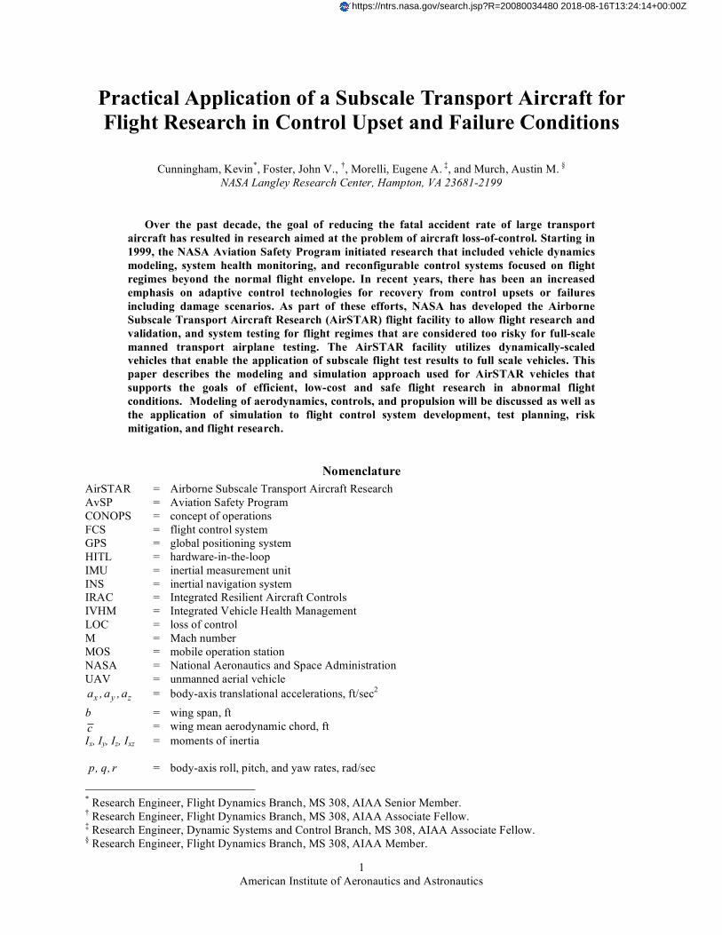
A. Description of AirSTAR Facility The AirSTAR infrastructure is comprised of a research flight vehicle, the mobile operation station (MOS), and
the safety pilot as illustrated in Fig. 1. The AirSTAR test vehicles range from small propeller-driven aircraft to turbine-powered, 5.5% dynamically-scaled generic transport airplanes. The MOS is comprised of a flight test control room and a research pilot station as well as systems and engineering stations. As illustrated in Fig. 1, takeoff and landing is accomplished by a safety pilot using direct visual contact and conventional radio control equipment. A research pilot executes flight test maneuvers from inside the MOS, using a synthetic vision display drawn from telemetry data and a local terrain database, while remaining within visual range of the safety pilot. Actuator commands from research pilot inputs and the ground-based flight control computer are transmitted to the aircraft by an L-band telemetry link. Computers in the MOS execute research flight control laws and interface with the research pilot station via direct connection. Sensor feedback from the aircraft to flight control system is via S-band telemetry link. While the model is being controlled from the research pilot station, a reversionary flight control capability is provided by a safety pilot. If a problem were to arise, the safety pilot can override the research pilot control inputs and fly via a hobbyist radio-control interface. This design provides a flexible environment to conduct flight research and rapidly evaluate research flight control laws with minimal risk.
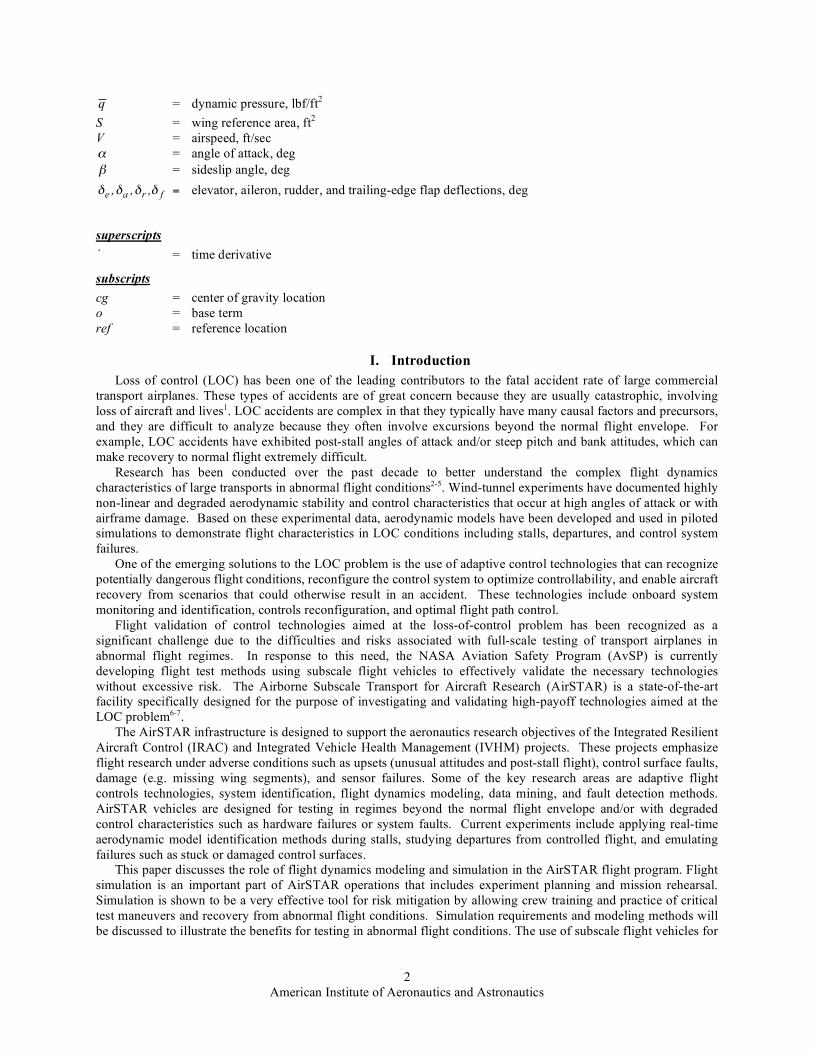
B. Test Aircraft The test aircraft that is specifically discussed in this paper, designated S-2, is a commercial off-the-shelf subscale
model of a jet transport aircraft. This vehicle is of similar weight and size (wing loading), with identical instrumentation, as the more expensive dynamically-scaled aircraft6. The S-2 model is currently being flown as a test surrogate for the dynamically-scaled aircraft for the purpose of developmental risk reduction. The S-2 aircraft has a single jet engine mounted in the aft fuselage and retractable tricycle landing gear. Control surfaces on the aircraft are conventional elevator, aileron, rudder, and inboard trailing-edge flaps. A photograph of the test aircraft in flight is shown in Fig. 2. Mass and geometry characteristics of this aircraft are given in Table 1.
Figure 1. Depiction of key elements of the AirSTAR infrastructure.
American Institute of Aeronautics and Astronautics
4
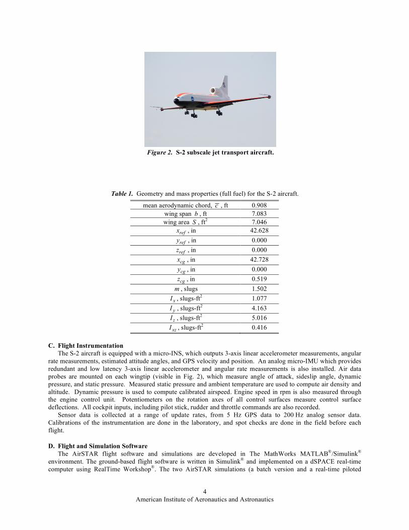
Table 1. Geometry and mass properties (full fuel) for the S-2 aircraft.
mean aerodynamic chord, c , ft 0.908 wing span b , ft 7.083 wing area S , ft2 7.046
refx , in 42.628
refy , in 0.000
refz , in 0.000
cgx , in 42.728
cgy , in 0.000
cgz , in 0.519 m , slugs 1.502
xI , slugs-ft2 1.077
yI , slugs-ft2 4.163
zI , slugs-ft2 5.016
xzI , slugs-ft2 0.416
C. Flight Instrumentation The S-2 aircraft is equipped with a micro-INS, which outputs 3-axis linear accelerometer measurements, angular
rate measurements, estimated attitude angles, and GPS velocity and position. An analog micro-IMU which provides redundant and low latency 3-axis linear accelerometer and angular rate measurements is also installed. Air data probes are mounted on each wingtip (visible in Fig. 2), which measure angle of attack, sideslip angle, dynamic pressure, and static pressure. Measured static pressure and ambient temperature are used to compute air density and altitude. Dynamic pressure is used to compute calibrated airspeed. Engine speed in rpm is also measured through the engine control unit. Potentiometers on the rotation axes of all control surfaces measure control surface deflections. All cockpit inputs, including pilot stick, rudder and throttle commands are also recorded.
Sensor data is collected at a range of update rates, from 5 Hz GPS data to 200 Hz analog sensor data. Calibrations of the instrumentation are done in the laboratory, and spot checks are done in the field before each flight.
D. Flight and Simulation Software The AirSTAR flight software and simulations are developed in The MathWorks MATLAB®/Simulink®
environment. The ground-based flight software is written in Simulink® and implemented on a dSPACE real-time computer using RealTime Workshop®. The two AirSTAR simulations (a batch version and a real-time piloted
Figure 2. S-2 subscale jet transport aircraft.
American Institute of Aeronautics and Astronautics
5
version) are developed and implemented in Simulink® and are used for flight control law development, system integration testing, Hardware-In-The-Loop (HITL) simulation, and mission rehearsals.
Each major component of the flight software and simulations exists as an individual library. The flight software and simulations draw from this common set of libraries to avoid code duplication, provide flexibility while maintaining configuration management, and to ensure consistent results from control law development through integration and testing. Both the batch and real-time simulations use a modular architecture that allows seamless simulation of different aircraft types by maintaining libraries for each aircraft, which are then simply selected prior to starting the simulation.
The real-time simulation supports HITL simulation by emulating the major components outside of the MOS, beginning with the serial data streams normally used to communicate with the aircraft via the L/S-band telemetry system. The simulation models the flight dynamics, aircraft systems, sensor characteristics, data system latencies, and telemetry system. With this configuration, there is no functional difference in the MOS systems and flight software between HITL simulation and flight operations. Mission rehearsals are conducted in the MOS using the real-time simulation and all of the MOS systems and flight software.
The primary component in the AirSTAR flight software is the Flight Control System (FCS). The FCS architecture for the AirSTAR facility has been designed to address the challenges associated with safe and efficient testing of research control laws in adverse flight conditions. The AirSTAR FCS has a flexible framework that allows rapid integration and testing of research control laws. Component or sensor failures can be emulated in the FCS. The FCS also has the capability to inject automated control surface perturbations to excite the aircraft dynamic response for modeling purposes. These control surface perturbations can have arbitrary waveforms, and can be applied to multiple control surfaces individually or simultaneously. The perturbations are summed with pilot and control system commands in the FCS, just before the command-limiting algorithm. A baseline control law is provided, which uses an angle of attack command augmentation system for the pitch axis and simple stability augmentation for the roll and yaw axes. Finally, a load protection system prevents the FCS from allowing the structural limits of the aircraft to be exceeded. The AirSTAR flight control system architecture is discussed in detail in Ref. 8.
E. Experimental Approach One of the primary objectives of the AirSTAR facility is to emulate flight behavior of a full-scale vehicle in
upset, failure, or damage conditions that are considered too risky for full-scale testing. In addition to eliminating the risk to an on-board flight crew, subscale vehicles may be designed for conditions that could exceed full-scale structural loads. Therefore the emphasis can be placed on a flexible research environment with the capability to rapidly implement, test, and evaluate experimental flight control laws and other algorithms. For example, aircraft flight characteristics in upset and LOC scenarios can be tested by flying the subscale vehicle into intentional stalls or departures and evaluating control system performance. Failure and damage conditions, such as a stuck control surface or inoperative sensor, can be emulated in the control law software.
A disadvantage of any subscale vehicle for experimental testing is the impact of scaling requirements when applied to full-scale scenarios. For some experiments, the AirSTAR vehicles are designed using similitude scaling laws9, often referred to as “dynamic scaling”. For the purposes of flight dynamics testing, the primary scaling requirements are for geometric, mass, time, and aerodynamic similitude. The geometric and mass scaling for the current vehicles is based on commercial transport airplanes using a scale factor of approximately 5.5%, resulting in sub-scale airplane weights of approximately 55-60 lbs. Time is scaled on the basis of equal Froude number resulting in the subscale vehicle angular rate response that is approximately 4.3 times faster than the full scale airplane. For closed-loop control experiments, similitude scaling also requires that flight control computer speed and actuator rates are time scaled based on the full scale vehicle control system.
An important limitation of any subscale test vehicle is in aerodynamic scaling. Because the AirSTAR vehicles are designed for low speeds, the experimental aerodynamic results are only considered valid for M < 0.45. Also, the Reynolds number of the subscale vehicle is much less than full scale, which can affect aerodynamic lift characteristics at some flight conditions. Both of these limitations must be considered when designing flight experiments or applying results to full scale vehicles.
III. Simulation Model Development and Validation
A. Simulation Development from Flight Data and Engine Tests Unlike the dynamically scaled test aircraft, no wind tunnel data or computational aerodynamic data were
available for the S-2 aircraft. Consequently, the aerodynamic model for the S-2 flight simulation was developed
American Institute of Aeronautics and Astronautics
6
exclusively from flight data. Engine data was obtained from installed thrust measurements during static ground tests.
This section describes the methods used to assemble the aerodynamic and engine models for the S-2 nonlinear simulation, and shows representative prediction results using the developed simulation. The engine model will be discussed first, followed by the aerodynamic model, and finally the prediction results.
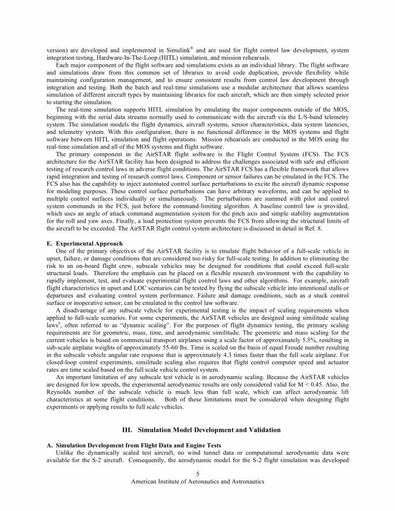
1. Engine Model The jet engine installed in S-2 is a JetCat P120SE. Ground tests with this engine included a static thrust test,
which produced the data shown in Fig. 3. Static thrust was modeled very well using a cubic function of the engine RPM, which was measured both during the ground tests and on the airplane in flight. The dashed line in Fig. 3 shows the excellent fit of the cubic model to the measured static thrust data. Cubic models were also identified to compute fuel flow from engine RPM, and to compute engine RPM from throttle position. The structure for each of these models was carefully identified using orthogonal function modeling and stepwise regression, see Ref. 10. Together, these models allowed simulation of steady-state engine RPM, fuel flow, and thrust as a function of throttle position.
Further ground testing involved step changes in throttle position, and measurement of engine RPM and thrust. A model for the RPM and thrust dynamic response was identified from this data, which included various step change amplitudes for both throttle forward and throttle back. A first-order dynamic model was identified, with a time constant that varied with thrust level. The engine thrust/RPM response was fastest at higher power levels, above 50 percent. Engine time constants varied from 0.85 sec to 1.96 sec.
Finally, a ram drag model was identified for the engine thrust, using level acceleration and deceleration flight maneuvers. During these maneuvers, there were brief periods of time when the angle of attack, pitch rate, altitude, and elevator deflection were relatively constant, while the engine RPM was increased or decreased. This means that approximately the entire change in the longitudinal acceleration was due to the engine thrust, after accounting for the angle of installation of the engine in the airframe, which was measured on the ground. Small corrections for the linear effects of angle of attack, pitch rate, and elevator deflection were made using stability and control derivatives estimated from 3-axis doublet maneuvers (see below). The remaining variation in the longitudinal acceleration was attributed to the engine. The change observed from the flight data (after linearized corrections) was compared with the change computed from the ground test data, with the difference assigned to ram drag. The ram drag was found to be a linear function of dynamic pressure, and was modeled in that way.
The ram drag correction was implemented in the engine model as a correction to the static thrust computed from ground test data and engine RPM. Engine dynamics were then applied to arrive at the simulated engine thrust.
2. Aerodynamic Model Flight data from two types of maneuvers were used to identify the global aerodynamic model. The first type was
a stall maneuver. This maneuver started at a low angle of attack trimmed flight condition followed by a reduction of thrust to idle, then pulling aft longitudinal stick to maintain a target airspeed deceleration rate until after the stall was identified, then recovering the aircraft to level flight. The stall maneuver was used to identify angle of attack dependencies and nonlinear aerodynamic behavior near the stall. The second maneuver type was a 3-axis doublet maneuver. In this case, the research pilot started from a trimmed level flight condition, and then applied doublets in pitch, yaw, and roll, in sequence. The pilot was instructed to make the timing of the doublets such that the pitch doublet period would be near 1 sec, with the yaw doublet period slightly longer, and the roll doublet period shorter. The doublet amplitudes were controlled by the research pilot so that aircraft responses in angle of attack and sideslip angle were within approximately 5 deg± from the initial trim values. The quality and precision of these maneuvers was enabled by use of the synthetic vision displays that are discussed later in this paper. The 3-axis doublet maneuvers were used to identify stability and control derivatives other than those associated with angle of attack.
Figure 3. JetCat P120SE static thrust.

American Institute of Aeronautics and Astronautics
7
The structure of the aerodynamic model was as follows:
( ) ( ) ( )2o q e
X X X X e
qcC C C C
V !" " " != + + (1a)
( ) ( ) ( )2o q e
Z Z Z Z e
qcC C C C
V !" " " != + + (1b)
( ) ( ) ( )2o q e
m m m m e
qcC C C C
V !" " " != + + (1c)
( ) ( ) ( ) ( ) ( )2o r a r
Y Y Y Y Y a Y r
rbC C C C C C
V! " "# # ! # # " # "= + + + + (1d)
( ) ( ) ( ) ( ) ( ) ( )2 2o p r a r
l l l l l l a l r
pb rbC C C C C C C
V V! " "# # ! # # # " # "= + + + + + (1e)
( ) ( ) ( ) ( ) ( ) ( )2 2o p r a r
n n n n n n a n r
pb rbC C C C C C C
V V! " "# # ! # # # " # "= + + + + + (1f)
It was assumed that the stability and control derivatives, such as ( )rn
C ! and ( )e
mC !" , were mainly functions
of low-frequency angle of attack, which is analogous to the trim angle of attack. These derivatives were estimated from individual 3-axis doublet maneuvers at various trimmed angle of attack flight conditions, and then cataloged as a function of trim angle of attack. The aerodynamic model for the nonlinear simulation linearly interpolates among these parameter estimates, using low-frequency angle of attack, to find the values to be used in the model structures of Eq. (1). The values of the stability and control derivatives at specific trimmed angle of attack conditions were computed using real-time parameter estimation in the frequency domain, as explained in detail in Refs. 10 and 11.
The base terms, such as ( )oZ
C ! , included both the angle of attack stability derivative behavior and the nonlinear character of the aerodynamics near stall. These terms were identified directly from the stall maneuvers described earlier, by subtracting off the best estimates of the other terms in Eq. (1), using the stability and control derivative estimates from the 3-axis doublets, and assigning the reminder to the base term. For example, ( )
oZC !
was computed from the stall maneuver data as
( ) ( ) ( )2o q e
Z Z Z Z e
qcC C C C
V !" " " != # # (2)
where ZC was computed from measured data, Z zC ma qS= , and the ( )2qZ
qcC
V! and ( )
eZ eC!
" ! terms were
computed using flight data from the stall maneuver and best estimates of the stability and control derivatives from the 3-axis doublet maneuvers. The same approach was used for the other force and moment coefficients.
Of course, a few assumptions were involved in building the aerodynamic model in this way. One is that the stability and control derivative identified from the 3-axis doublets can be applied to the entire stall maneuver, which covers a large range in angle of attack. Error is introduced here, because the 3-axis doublets were generally done at trim angles of attack well below the stall, yet the linearized derivative information was used through the stall in computing base terms like ( )
oZC ! . Future flight testing will eliminate this error source by applying automated
3-axis perturbation excitations through the entire stall maneuver, including the stall break and recovery. Another assumption was that the aerodynamic dependencies can be modeled as linear in the non-dimensional angular rates and control surface deflections. Experience with aircraft system identification and wind tunnel testing on other aircraft shows that these are generally good assumptions, except in highly nonlinear aerodynamic flight conditions,
American Institute of Aeronautics and Astronautics
8
such as near stall. Future flight testing with perturbations through the stall and recovery are also expected to shed light on the accuracy of this assumption and perhaps suggest approaches for improving the modeling near stall.
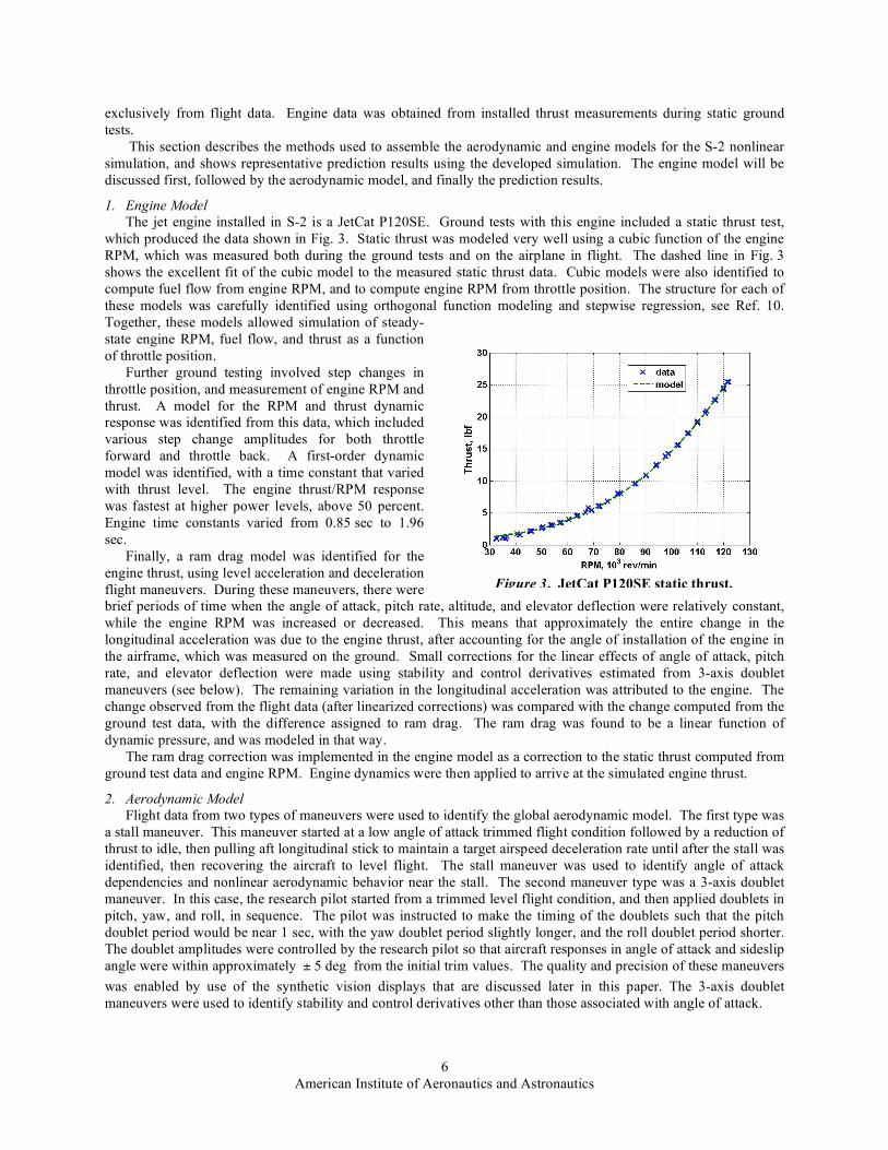
3. Simulation Model Prediction Tests The ultimate measure of any model is prediction accuracy. Fig. 4 shows a prediction case using the S-2
nonlinear simulation. Flight data for the engine RPM and control surface deflections from a yaw-roll doublet maneuver were used as inputs to the nonlinear simulation to predict flight responses of the S-2 aircraft. The flight data for this doublet maneuver was not part of the data used to identify the aerodynamic model for the S-2 nonlinear simulation. Comparison of the measured and simulation responses shows that the S-2 nonlinear simulation captures the dynamic character of the S-2 aircraft for this 80 knot flight condition, which is roughly in the middle of the flight envelope. More flight data near the stall will be collected in future flight tests, which will allow assessment of the prediction capability of the nonlinear simulation near stall.
Figure 4. Comparison of S-2 flight data to simulation prediction.
American Institute of Aeronautics and Astronautics
9
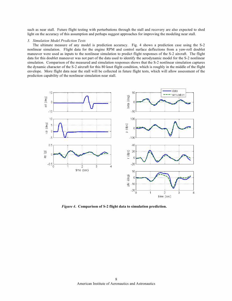
B. Flight Test Results An example of real-time parameter estimation results is shown in Fig. 5, which compares real-time parameter
estimates (diamond markers) and associated 95 percent confidence intervals (vertical bars through the diamond markers) with estimates obtained using the output-error method (dashed lines) for a 3-axis doublet maneuver. The output-error method is a batch method that uses the data iteratively with a nonlinear optimizer to arrive at the model parameter estimates10. The data used in the output-error method has been corrected for sensor position errors and for systematic instrumentation errors, using data compatibility analysis10. The batch output-error method with corrected data is generally recognized as the most accurate method available for estimating dynamic model parameters. The real-time parameter estimation method uses flight data corrected only for sensor position errors (i.e., not corrected for systematic instrumentation errors), and the data is used only once (as opposed to iteratively), with results available in real time. The comparison shows that the real-time method needs only a few seconds of good quality data to achieve the same parameter estimate accuracy as the batch output-error method with corrected data. The results shown here are in agreement with previous similar comparisons12. Real-time parameter estimates such as these were used in the model structures of Eq. (1) to supply values for the stability and control derivatives, excluding the angle of attack derivatives.
IV. Applications of Simulation to System Design and Risk Mitigation.
A. Ground System Development Simulation has been used extensively in the development of AirSTAR ground systems that include the cockpit,
pilot and flight test engineer displays, and flight control system. Due to the limited test range, which is further discussed in Section C below, certain flight test maneuvers such as stalls, upsets, and failure emulation must be completed quickly to remain within boundaries. Therefore the human-machine interface plays a critical role in enabling precise aircraft control and safety during “time compressed” events.
The research pilot station, shown in Fig. 6, has a primary flight display which is a synthetic view combining out-
the-window scenery with standard head-up display symbology that includes angle of attack and normal load factor
Figure 5. Real-time dynamic modeling results from S-2 flight data for a 3-axis doublet maneuver.
American Institute of Aeronautics and Astronautics
10
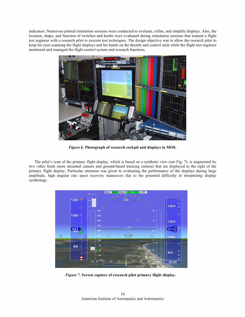
indicators. Numerous piloted simulation sessions were conducted to evaluate, refine, and simplify displays. Also, the location, shape, and function of switches and knobs were evaluated during simulation sessions that teamed a flight test engineer with a research pilot to execute test techniques. The design objective was to allow the research pilot to keep his eyes scanning the flight displays and his hands on the throttle and control stick while the flight test engineer monitored and managed the flight control system and research functions.
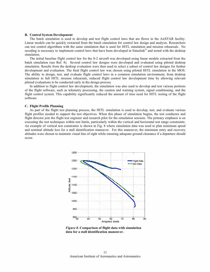
The pilot’s scan of the primary flight display, which is based on a synthetic view (see Fig. 7), is augmented by
two video feeds (nose mounted camera and ground-based tracking camera) that are displayed to the right of the primary flight display. Particular attention was given to evaluating the performance of the displays during large amplitude, high angular rate upset recovery maneuvers due to the potential difficulty in interpreting display symbology.
Figure 7. Screen capture of research pilot primary flight display.
Figure 6. Photograph of research cockpit and displays in MOS.
American Institute of Aeronautics and Astronautics
11
B. Control System Development The batch simulation is used to develop and test flight control laws that are flown in the AirSTAR facility.
Linear models can be quickly extracted from the batch simulation for control law design and analysis. Researchers can test control algorithms with the same simulation that is used for HITL simulation and mission rehearsals. No recoding is necessary to implement control laws that have been developed in Simulink® and tested with the desktop simulation.
The initial baseline flight control law for the S-2 aircraft was developed using linear models extracted from the batch simulation (see Ref. 8). Several control law designs were developed and evaluated using piloted desktop simulation. Results from the desktop evaluation were then used to select a subset of control law designs for further development and evaluation. The final flight control law was chosen using piloted HITL simulation in the MOS. The ability to design, test, and evaluate flight control laws in a common simulation environment, from desktop simulation to full HITL mission rehearsals, reduced flight control law development time by allowing relevant piloted evaluations to be conducted early in the design process.
In addition to flight control law development, the simulation was also used to develop and test various portions of the flight software, such as telemetry processing, the caution and warning system, signal conditioning, and the flight control system. This capability significantly reduced the amount of time need for HITL testing of the flight software.
C. Flight Profile Planning As part of the flight test planning process, the HITL simulation is used to develop, test, and evaluate various
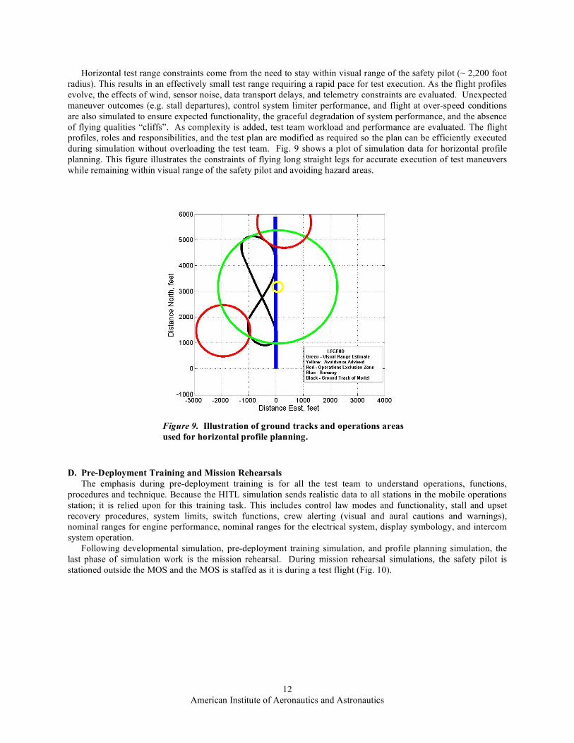
flight profiles needed to support the test objectives. When this phase of simulation begins, the test conductor and flight director join the flight test engineer and research pilot for the simulation sessions. The primary emphasis is on executing the test techniques within test limits, particularly within the vertical and horizontal test range constraints. An example of vertical test constraints is shown in Fig. 8 where simulation data was used to plan minimum speed and nominal altitude loss for a stall identification maneuver. For this maneuver, the minimum entry and recovery altitudes were chosen to maintain visual line of sight while ensuring adequate ground clearance if a departure should occur.
Figure 8. Comparison of flight data with simulation data for a stall identification maneuver.
American Institute of Aeronautics and Astronautics
12
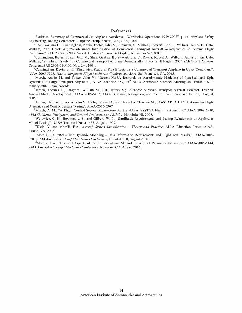
Horizontal test range constraints come from the need to stay within visual range of the safety pilot (~ 2,200 foot radius). This results in an effectively small test range requiring a rapid pace for test execution. As the flight profiles evolve, the effects of wind, sensor noise, data transport delays, and telemetry constraints are evaluated. Unexpected maneuver outcomes (e.g. stall departures), control system limiter performance, and flight at over-speed conditions are also simulated to ensure expected functionality, the graceful degradation of system performance, and the absence of flying qualities “cliffs”. As complexity is added, test team workload and performance are evaluated. The flight profiles, roles and responsibilities, and the test plan are modified as required so the plan can be efficiently executed during simulation without overloading the test team. Fig. 9 shows a plot of simulation data for horizontal profile planning. This figure illustrates the constraints of flying long straight legs for accurate execution of test maneuvers while remaining within visual range of the safety pilot and avoiding hazard areas.
D. Pre-Deployment Training and Mission Rehearsals The emphasis during pre-deployment training is for all the test team to understand operations, functions,
procedures and technique. Because the HITL simulation sends realistic data to all stations in the mobile operations station; it is relied upon for this training task. This includes control law modes and functionality, stall and upset recovery procedures, system limits, switch functions, crew alerting (visual and aural cautions and warnings), nominal ranges for engine performance, nominal ranges for the electrical system, display symbology, and intercom system operation.
Following developmental simulation, pre-deployment training simulation, and profile planning simulation, the last phase of simulation work is the mission rehearsal. During mission rehearsal simulations, the safety pilot is stationed outside the MOS and the MOS is staffed as it is during a test flight (Fig. 10).
Figure 9. Illustration of ground tracks and operations areas used for horizontal profile planning.

American Institute of Aeronautics and Astronautics
13
During the mission rehearsals, the emphasis is on the realistic simulation of particular research flight profiles
from takeoff to landing with the goal of completing all flight test cards planned for that flight. All checklists, procedures, and callouts are executed as they would be during a real flight. The safety pilot initially flies the simulation via a display setup outside the MOS. He flies the model to the handoff point and coordinates the handoff with the research pilot using the same communications equipment that is used during a test. In addition to simulating nominal coordinated handoffs between the pilots, the procedures for abnormal scenarios are practiced. For the situation where the safety pilot unilaterally takes control, the scenarios include: descent below research system minimum altitude, execution of an un-briefed maneuver, flight beyond operations area, and loss of telemetry link. The mission rehearsal simulations have been very beneficial for the test team to establish disciplined and efficient behaviors and communications for use during time compressed flight test events.
V. Concluding Remarks AirSTAR is a state-of-the-art flight test facility specifically designed for validation of technologies intended to
reduce loss-of-control accidents. This facility operates highly-instrumented turbine-powered vehicles, representative of large transport airplanes, which can be tested in abnormal flight conditions that are otherwise too risky for full scale testing.
Modeling and simulation is an integral and necessary part of the AirSTAR system that is used for vehicle development, flight planning and training, and control system research. To date, high-fidelity simulations for two research vehicles have been developed; one for a COTS vehicle using in-flight estimation methods and a second one for a custom built proprietary configuration based on extensive static and dynamic wind tunnel testing.
Flight experiments are in progress that include real-time system identification, advanced controls design for recovery from upset conditions, and advanced methods for air data measurements. The current flights are being made with the COTS aircraft, which serves as a surrogate vehicle for the more expensive dynamically scaled test article. Flight-testing of the COTS vehicle has been supported by piloted simulation for the purposes of operations training, test maneuver development, pilot display design, and research software development. Future flight testing is planned for the dynamically scaled vehicle which will incorporate lessons learned and risk mitigation strategies developed from the COTS vehicle.
Acknowledgments The efforts of the AirSTAR flight test team at NASA Langley in building and testing the aircraft and associated
systems, carefully calibrating the instrumentation, and carrying out the flight operations to collect the high-quality flight data used in this study, are gratefully acknowledged.
Research
PilotTest
Conductor
Communications
External Data &
Communications
Flight Test
Engineer
Hardware
Engineer
Software
Engineer
Flight
DirectorResearcher
ComputersRPV Cockpit
Flight Test Control Room
Video & Power
Distribution
Research
PilotTest
Conductor
Communications
External Data &
Communications
Flight Test
Engineer
Hardware
Engineer
Software
Engineer
Flight
DirectorResearcher
ComputersRPV Cockpit
Flight Test Control Room
Video & Power
Distribution
Figure 10. Functional layout of the mobile operation station as staffed during flight and mission rehearsal simulations.
American Institute of Aeronautics and Astronautics
14
References 1Statistical Summary of Commercial Jet Airplane Accidents – Worldwide Operations 1959-2003”, p. 16, Airplane Safety
Engineering, Boeing Commercial Airplane Group, Seattle, WA, USA, 2004. 2Shah, Gautam H., Cunningham, Kevin, Foster, John V., Fremaux, C. Michael, Stewart, Eric C., Wilborn, James E., Gato,
William, Pratt, Derek W.; “Wind-Tunnel Investigation of Commercial Transport Aircraft Aerodynamics at Extreme Flight Conditions”, SAE 2002-01-2912, World Aviation Congress & Display, November 5-7, 2002.
3Cunnngham, Kevin, Foster, John V., Shah, Gautam H., Stewart, Eric C., Rivers, Robert A., Wilborn, James E., and Gato, William, “Simulation Study of a Commercial Transport Airplane During Stall and Post-Stall Flight”, 2004 SAE World Aviation Congress, SAE 2004-01-3100, Nov. 2-4, 2004.
4Cunningham, Kevin, et al, “Simulation Study of Flap Effects on a Commercial Transport Airplane in Upset Conditions”, AIAA-2005-5908, AIAA Atmospheric Flight Mechanics Conference, AIAA, San Francisco, CA, 2005.
5Murch, Austin M. and Foster, John V.; “Recent NASA Research on Aerodynamic Modeling of Post-Stall and Spin Dynamics of Large Transport Airplanes”, AIAA-2007-463-253, 45th AIAA Aerospace Sciences Meeting and Exhibit, 8-11 January 2007, Reno, Nevada.
6Jordan, Thomas L., Langford, William M., Hill, Jeffrey S.; “Airborne Subscale Transport Aircraft Research Testbed: Aircraft Model Development”, AIAA 2005-6432, AIAA Guidance, Navigation, and Control Conference and Exhibit, August, 2005.
7Jordan, Thomas L., Foster, John V., Bailey, Roger M., and Belcastro, Christine M.; “AirSTAR: A UAV Platform for Flight Dynamics and Control System Testing”, AIAA-2006-3307.
8Murch, A. M., “A Flight Control System Architecture for the NASA AirSTAR Flight Test Facility,” AIAA 2008-6990, AIAA Guidance, Navigation, and Control Conference and Exhibit, Honolulu, HI, 2008.
9Wolowicz, C. H.; Bowman, J. S.; and Gilbert, W. P., “Similitude Requirements and Scaling Relationship as Applied to Model Testing”, NASA Technical Paper 1435, August, 1979.
10Klein, V. and Morelli, E.A., Aircraft System Identification – Theory and Practice, AIAA Education Series, AIAA, Reston, VA, 2006.
11Morelli, E.A. “Real-Time Dynamic Modeling – Data Information Requirements and Flight Test Results,” AIAA-2008-6201, AIAA Atmospheric Flight Mechanics Conference, Honolulu, HI, August 2008.
12Morelli, E.A., “Practical Aspects of the Equation-Error Method for Aircraft Parameter Estimation,” AIAA-2006-6144, AIAA Atmospheric Flight Mechanics Conference, Keystone, CO, August 2006.