support tube removal-5
TRANSCRIPT
Page 1 of 51
Report on the Support Tube Removal from the BaBar Detector
Aug 1, 2002
People present:
Mike Sullivan Mohammad Dormiani Richard Boyce Stan Ecklund
MFD technicians: Jeff Aldrich Dan Cox
Rigger:
Dave Engesser
Many other people were present throughout most of the removal: Frank O’Neill Roy Kerth Mike Wilson SVT monitor group
Preparatory tasks: Prior to the event, preparations such as alignment of the insertion beam etc., were made to make the support tube removal possible, see Appendix A for details. In the course of doing these preparatory tasks, Stuart Metcalfe’s notes (Appendix B), Martin Nordby’s instructions (Appendix C), relevant drawings (Appendix D) and consultations with people who had been involved with building and installing various components of the support tube and drift chamber were used for guidance. Description of the event: The support tube removal started in the morning of July 31, 2002. The weight of the tube was transferred to the beam on the backward side and to the crane on the forward side while the SVT position monitoring cables were connected. The tube is pushed out of the detector from the backward side (DIRC tunnel). After an initial inspection with some minor cable redressing the move was started. Mike Sullivan, with Richard Boyce and Mohammad Dormiani, was on the beam side of the support tube with Richard and Mohammad pushing the beam using a come-along and Mike as the primary observer inside the DIRC tunnel. When he was not assisting Mohammad, Richard was inside the DIRC tunnel with Mike watching the support tube. On the forward side we had the 2 MFD technicians watching the support tube as it exited the detector with Dave Engesser who operated the crane. Stan Ecklund spent time on both sides and also came into the
Page 2 of 51
DIRC tunnel to inspect the removal progress. We used two-way radio to communicate between the two sides. See Figures 1 through 5 for general views of the setup. The removal started smoothly, but we had only moved about 0.5” when we found that the support tube wanted to drift to the west (inside of the ring). This was attributed to a slight kink between the beam and the support tube. The tube was pushing fairly strongly on the western stop on the forward side. After much consultation and discussion, we compensated for this by adjusting the outboard beam support to the west, which rotates the beam about the inboard support; Figure 4 shows this support. This cleared up the problem, and we proceeded to continue pushing the support tube out. As the support tube backward end entered the drift chamber hole, Mike noticed that the 4 bolts used to mount the fixture that connects the beam to the support tube had heads that stuck out from the outer radius of the support tube. These are 1/2” bolts. He mentioned this to Richard and they agreed that these bolt heads were the thing to watch as we were going through the drift chamber. As we continued pushing out the support tube we never traveled more than about 6 inches, and in one inch intervals, before stopping and looking around the support tube as much as possible. The support tube backward end started drifting to the east fairly soon after entering the drift chamber, and several times we compensated for this by adjusting primarily the outboard beam support to the east, rotating the beam about the inboard support and shifting the support tube to the west. At all times we watched the end of the support tube and verified that we could see light around all sides. At about 11:30, Mike Sullivan and Jeff Aldrich both heard a pinging sound. We immediately stopped and closely inspected the support tube and could not see anything touching. We moved a little more and heard a second, softer ping. We looked around again and did not see anything touching. We did notice that the support tube was closer to the east side than to the west side so we moved the outboard beam support to the east to shift the support tube to the west. It was at this time that the drift chamber people reported that they had had a pressure drop and were leaking gas somewhere. By this time the backward end of the support tube was inside the Be tube of the drift chamber; we were about halfway through. We again noticed that the support tube was closer to the eastern side than the western side and adjusted the outboard beam support again. However, even at this time we could still see light around the entire tube and hence concluded that the tube was not touching the drift chamber. Several times during the removal we also adjusted the height of the support tube. This process continued in much the same fashion until near the end when the spotters on the forward side could finally see that the support tube was very close to the eastern side. They still did not say the tube was touching. We then adjusted the outboard beam support again by moving it in the eastern direction and got the support tube more centered. We then proceeded to complete the removal. Once the support tube was removed we could see that something had put a long scratch along the eastern side of the drift chamber a few inches below the horizontal plane. We could also see that the Be tube had a deformation that looked like a crack. This crack also looked like it had started near to where the scratch had started; see Figure 6 through 8. The present analysis is as follows:
Page 3 of 51
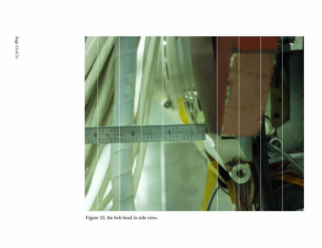
The scratch on the drift chamber is very close in azimuth to the lower bolt head of the beam fixture; see Figures 9 and 10. About the same elevation there are hinged sensors, which two views of one of them are shown in Figures 11 and 12. No one was sure of what caused the scratch. It generally became obvious that the lower east bolt head (colored red in Figure 13) had to have caused the damage. We have concluded that the bolt head sticks out far enough that optically the support tube looks well clear of the drift chamber even when the bolt is already touching. We were apparently not able to see the bolt head after the support tube had moved more than about 1.5 m into the drift chamber. So, even though everything looked fine, we were actually pushing on the drift chamber Be tube with considerable force with the corner of the bolt head. This corner then generated large stresses at the contact point which then cracked the Be. Figure 14 shows that the bolt heads reduces the clearance from above 10.5 mm to below 3 mm. This tight clearance was not known, or documented, or communicated by anybody to the people involved in the support tube removal before the event. Suggested remedies: Right now we have come up with the following procedural changes and possible enhancements to prevent this from happening again:
• Use a low profile button head cap screw with no washer. • Electrically isolate the support tube and look for a short to ground and monitor the
support tube’s capacitance to ground. This will tell us if we are touching even if we can’t see the contact point. Caveat: The Be tube is coated with epoxy paint and would not show a short to ground until one had scratched the paint. Or make a thin shell with outside insulated and inside conducting electricity so the short can be detected when there is contact between this shell and the support tube.
• Use thin strips of G10 or some other plastic to slide around the tube to see if there are any interferences. If these strips are as long as the drift chamber, this could be done at any time and periodically prove that nothing is touching. One has to be careful that the strips do not hang up on anything sticking out of the support tube.
• Mount proximity sensors on the support tube backward end to measure the distance to the drift chamber. At the forward end use proximity sensors mounted on the drift chamber end. This would give a real-time readout of the support tube position as it is moved through the drift chamber.
• Flood the backward chamber with light and look from the forward side to see the clearance rather than using a flashlight, which produces reflections that can deceive eyes.
Hindsight is always clearer, but it is important to understand what happened in order to prevent a future occurrence. We feel we can prevent this accident from happening again by incorporating the above changes and will continue to think of other improvements to our procedure. A final note: installing the support tube is easier than removing it, because pre-alignment of the insertion beam can be thoroughly checked when no support tube is present. Any further comments and suggestions are definitely welcome.
Page 4 of 51
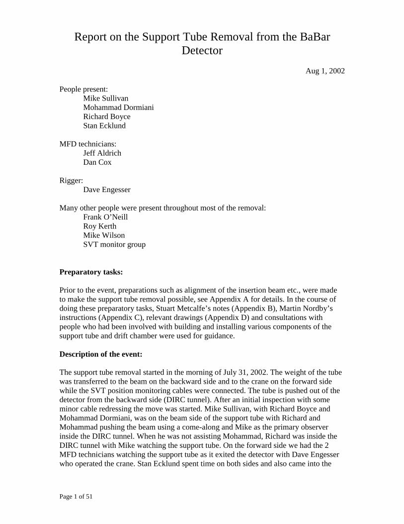
Figure 1 View showing the fixture which connects the insertion beam to the support tube.
Page 5 of 51
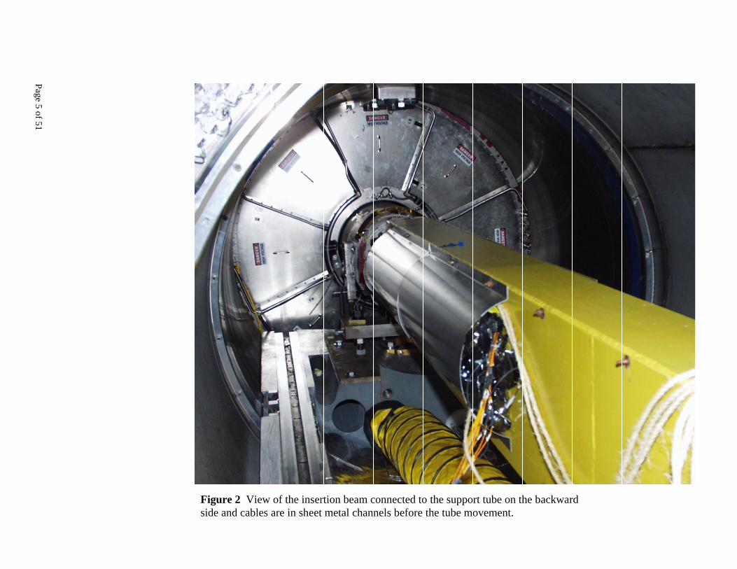
Figure 2 View of the insertion beam connected to the support tube on the backward side and cables are in sheet metal channels before the tube movement.

Page 6 of 51
Figure 3 Insertion beam after it has moved some distance toward the forward side.
Page 7 of 51
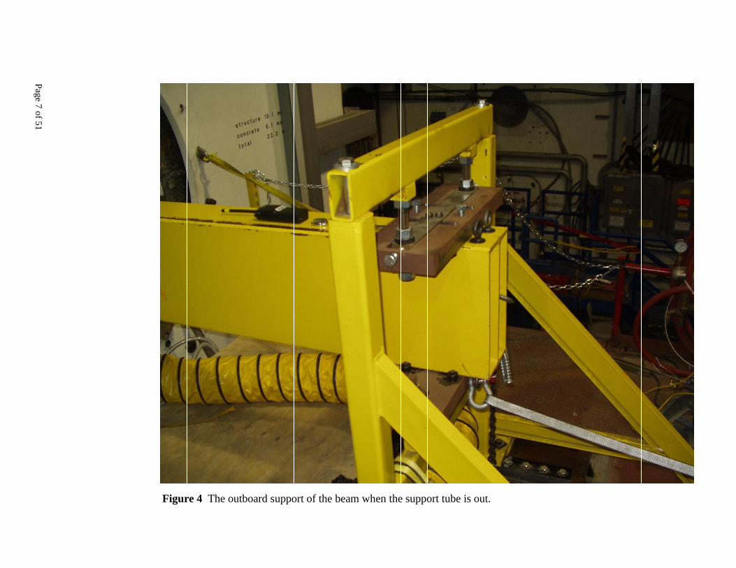
Figure 4 The outboard support of the beam when the support tube is out.
Page 8 of 51
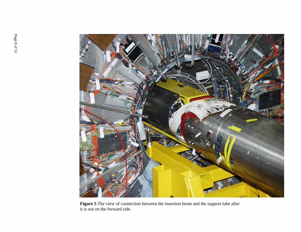
Figure 5 The view of connection between the insertion beam and the support tube after it is out on the forward side.

Page 9 of 51
Figure 6 Beryllium crack in close up.

Page 10 of 51
Figure 7 Beryllium tube scratch and crack.
Page 11 of 51
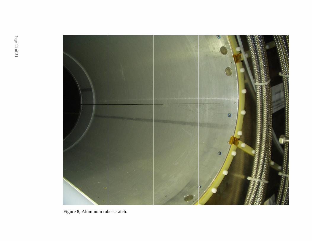
Figure 8, Aluminum tube scratch.

Page 12 of 51
Figure 9, bolt head connecting the support tube to the fixture on the insertion beam.
Page 13 of 51
Figure 10, the bolt head in side view.

Page 14 of 51
Figure 11, hinged sensors on the side of the support tube.

Page 15 of 51
Figure 12, hinged sensor in side view.

Page 16 of 51
Figure 13, model of the support tube and the fixture; red bolt head is at approximate level of the scratch to the drift tube.

Page 17 of 51
Figure 14, the clearance with and without the bolt heads.

Page 18 of 51
Appendix A Preparation Tasks
Page 19 of 51
Stuart Metcalfe was involved in developing the schedule for support tube removal and related tasks for several months and oversaw the preparations tasks until and including July 25, 2002. Then he took two weeks of unavoidable but expected leave. Mohammad Dormiani was substituted for Stuart on July 26. Before leaving, Suart gave Mohammad his notes (Appendix B) and Martin Nordby’s instructions for inserting the support tube (Appendix C). Mohammad consulted Richard Boyce on many occasions during the preparation for the removal of the support tube. Richard and Mohammad had a conference call on July 30 with Martin Nordby regarding this project. Because Martin had to be in GLAST review, he could not be present during the operation. Dave Engesser was scheduled to work for this project from July 29 through 31. Postponement of the task would have delayed other projects too. The following daily reports describes the preparations tasks starting July 26 in more detail: ========================================================================= From: Dormiani, Mohammad Sent: Friday, July 26, 2002 5:59 PM To: Metcalfe, Stuart J.; Bostic, David E.; Giannini, Leo Cc: Zurawel, Michael H.; Wright, Daniel; Ecklund, Stan; Sullivan, Michael;
Bong, Eric Lind; DeBarger, Scott; O’Neill, Frank G.; Boyce, Richard F.; Edwards, Adam Jacob; Petersen, Brian Aagaard
Subject: Friday tasks summary The remaining support pad was made. The forward Q2/Q1 bellows have been removed. Extension table was installed. Temporary support for the forward side of the support tube was installed. No work is scheduled for the weekend. Monday morning the load will be transferred to the temporary support. But before doing that, the position monitor cables need to be connected. Adam Edwards (x2889) and Brian Peterson (x2889) would like to connect the cables and monitor the movement of the support tube while the load is transferred to the temporary support. This monitoring needs to be done for all movements of the support tube even when it is on the truck. Today we had a lot of unexpected problems, big and small, that potentially could have delayed us considerably. But we were fortunate to have Richard F. Boyce help. He was there for all day and he helped on all aspects of the today tasks. Without his, resourcefulness, efforts and suggestions today’s tasks would have not been done. Thanks Richard. Mohammad ========================================================================= From: Dormiani, Mohammad Sent: Monday, July 29, 2002 7:03 PM To: Metcalfe, Stuart J.; Bostic, David E.; Giannini, Leo Cc: Zurawel, Michael H.; Wright, Daniel; Ecklund, Stan; Sullivan, Michael;
Bong, Eric Lind; DeBarger, Scott; O’Neill, Frank G.; Boyce, Richard F.; Edwards, Adam Jacob; Petersen, Brian Aagaard; Wilson, Michael Galante
Subject: Monday tasks summary The support tube load was transferred to temporary support. The forward raft was craned out of IR2 and moved to heavy fabrication building. The insertion beam was aligned with the center of the drift tube. The sheet metal cable holders are going to be made tomorrow. The preparation for the support tube removal will continue tomorrow.

Page 20 of 51
Mohammad ========================================================================= From: Dormiani, Mohammad Sent: Tuesday, July 30, 2002 5:50 PM To: Metcalfe, Stuart J.; Bostic, David E.; Giannini, Leo Cc: Zurawel, Michael H.; Wright, Daniel; Ecklund, Stan; Sullivan, Michael;
Bong, Eric Lind; DeBarger, Scott; O’Neill, Frank G.; Boyce, Richard F.; Edwards, Adam Jacob; Petersen, Brian Aagaard; Wilson, Michael Galante; Smith, Bennett C.; ’[email protected]’
Subject: Tuesday (7/30) tasks summary Crane mounting brackets were installed. The sheet metal cable holders were made and installed. The blue frame was prepared for the tube. The support table in vacuum shop is ready for the support tube. The work on fitting the cables in sheet metal channels is in progress. We plan to remove the support tube from the detector and move it to the vacuum shop tomorrow (Wednesday 7/31). Mohammad ========================================================================= From: Dormiani, Mohammad Sent: Wednesday, July 31, 2002 6:54 PM To: Metcalfe, Stuart J.; Bostic, David E.; Giannini, Leo Cc: Zurawel, Michael H.; Wright, Daniel; Ecklund, Stan; Sullivan, Michael;
Bong, Eric Lind; DeBarger, Scott; O’Neill, Frank G.; Boyce, Richard F.; Edwards, Adam Jacob; Petersen, Brian Aagaard; Wilson, Michael Galante; Smith, Bennett C.; ’[email protected]’
Subject: Wednesday (7/31) tasks summary Preparation for support tube removal continued from yesterday. The support tube was pushed out of the drift chamber and craned out to the IR2 hall and then loaded on the truck. Because there was not sufficient time to transfer the tube to the vacuum shop, it was transferred to the heavy fabrication building. During the ST removal, drift chamber lost its gas pressure. There is a visible scratch mark on and along the support tube on part of beryllium and aluminum section. There is another short scratch (crack? hole and crack? hole and scratch?) on the beryllium surface. This short scratch makes steep angle with the centerline of the tube. At least five people were watching the clearance of the tube with the surface of the drift chamber on both sides during the removal of the tube. The direction of the tube was adjusted many times to make sure that it would not touch the drift tube. There is no visible sign on the support tube that indicates there was a contact between the tube and the surface of the drift chamber. So far it is not clear what touched the surface of the drift chamber. Tomorrow (8/1) the support tube is going to be moved from heavy fab. to the clean room in the vacuum shop and mounted on the table in that room. Mohammad

Page 21 of 51
Appendix B Stuart Metcalfe Notes

Page 22 of 51
To Do list, Thursday 25th onwards. S.J.Metcalfe 7/24/02 Continue disconnecting pipes and cables between the forward raft and support tube. Remove bellows Insert extension table for Forward Calorimeter extraction system. This table is currently in the IR2 outer hall. Use care when handling to avoid damage to the rails.
a) Crane in Extension Table, place it on the floor plates approx. 2 feet to the east of its final position with its four castors pointing towards the east to ensure that the table travels towards the west.
b) Wind down the four castors using 5/8” AF sockets so that they just take the load
off the leveling feet.
c) Push the table towards the west, close to its final position i.e. the two flanges are nearly touching.
d) Wind up the four castors so that each leveling foot is firmly on the floor.
e) Rough align leveling feet so that bolts can be inserted.
f) Check that the rails are approximately level. Adjust leveling feet nearest BaBar as
required to level the rails.
g) On this occasion it will not be necessary to insert the taper dowel pins to closely align the rails. Protect exposed rails.
h) Tighten all eight bolts and nuts to secure the table.
Insert forward S.T. temporary support frame (SA 343-931-70), which is item 5 on GP 343-931-60. Suggested procedure:
a) Remove fasteners securing the top and bottom halves of the frame and separate the two halves. Also remove brackets items 4 and 5 and threaded rods item 6.
b) Place a large piece of plywood on the extension table (to protect the rails) and position the top half of the frame on the plywood then crane up until the two arms of the frame enter the center of the forward calorimeter and the blocks at the end of the arms are underneath the support tube (arms will be horizontal in installed position).
c) During this process, avoid touching the raft, S.T. and any components inside the center of the F.C. If anything in there interferes with the installation, move it or remove it!
d) Next place the protective rail pads on top of the extension frame. There are 2x pad type 1 (pf 343-931-68) and these go on the end of the table nearest BaBar. The other two pads are handed and fit at the other end. This isn’t shown on the assy

Page 23 of 51
drg yet. If in doubt, call Catherine Carr x2168 for further information. One of the type 1 pads is still being manufactured and is expected to be finished on Friday 26th (Just In Time!)– call Jon Simpson for status.
e) Slide the bottom half of the frame in from the side, sit it on the rail pads and bolt down. Note: check fit the frame on the extension table before starting this operation.
f) Add 4 shim plates then join together and bolt up the two halves of the frame. g) Attach threaded rods (item 6) to arms. h) Attach mounting clamps (343-931-60 items 8 and 9) to the support tube.
Fasteners are in the box. i) Attach adjustment brackets (items 4 and 5) to end of arms. j) Adjust threaded rods upwards until they contact the underside of the mounting
clamps then continue turning approx ¼ turn to apply some preload. k) Adjust pusher screws item 9 to contact mounting clamps.
Transfer S.T. load from raft to temporary support by adjusting yoke. Minimize support tube vertical movement by checking with a dial indicator and adjust threaded rods item 6 up or down as required. Disconnect yoke from support tube. Attach crane to forward raft without lifting (at this stage). Use ‘come along’ to slide raft in Z by approx 6” away from BaBar. Note, the dowel pin at the front of the raft has been removed and the slides at the back of the raft allow the raft to move only in Z. Avoid any movement in X at the front of the raft at least until the raft has cleared the support tube. Remove 4 bolts each side of the underside of the raft that secure it to the slide plates. Crane the raft out and transport to Heavy Fab. Commence Q2 chamber replacement procedure (open magnets, disconnect cables, pipes etc) but wait for me to return before removing and replacing Q2 chamber. Attach crane mount brackets (PF343-931-65) to front of support tube. These brackets are currently on top of Q5 magnet. Fasteners are in the box. Martin Nordby wrote a very detailed procedure for installing the support tube in BaBar (STInsertion.doc attached) so I suggest that you follow it in reverse order to remove the support tube. A few notes that come to mind:
a) Remember to call in Tony King to align the roller plates sometime before starting – the beam hook is currently pitched downwards about ¼” below the support tube pickup bar and has an additional wood support at the back which will need to be removed – use 200lb of counterbalance on the beam inside the DIRC tunnel to prevent the beam from lifting up and hitting the S.T. when removing the wood.
b) Rig a come along to pull the back of the beam (in the tunnel) towards the IP – don’t pull the support tube from the front end, use the beam to slowly push it
Page 24 of 51
through. Also rig a come along to act as a brake – better, I think, than using the built-in braking screws given the twist in the beam (see para. e below)
c) Before rolling out the S.T, crane up the appropriate cribbing to support the front end of the S.T. whilst the crane is being rigged to carry the S.T. away (yellow beam, currently in front of IR2). Probably use 2 or 3 of the 12x12’s that we used to support the rear raft plate.
d) After attaching SVT cables to side of beam (before rollout), check outside diameter of S.T. for anything sticking out which could catch on the inside of the drift chamber.
e) The insertion beam has a slight bend and twist so the roller plates must be adjusted to compensate and keep the S.T. in the center of the drift chamber during rollout.
f) Remember to disconnect the S.T. ‘Z’ adjuster turnbuckle at the underside of the S.T. in the DIRC tunnel before commencing rollout (see para. 39 of procedure) otherwise the S.T. won’t go anywhere!
g) Take photographs and note any errors in the procedure – I’ll rewrite it later for removal of the support tube.
Withdraw S.T. temporary support (probably don’t need to disassemble) in Z until it clears the opening then crane out. Protect rails on extension table with plywood during withdrawal. Crane out the gray extension table. Close the forward doors.

Page 25 of 51
Appendix C Martin Nordby Instructions
Page 26 of 51
Support Tube Insertion into BaBar Martin Nordby
Revision history: • 19 April 19, 1999: Modified based on insertion experience.
Few mod’s of significance needed. • 2 April, 1999: First release for BaBar installation
Prep IR-2 for ST Insertion
1. Prep Back End
• Move BV1 Raft and HER beamline components into tunnel, so first 6 feet of tunnel are clear.
• Remove Slider Plate assemblies from Q5 Raft supports. Protect bottom surfaces from scratching.
2. Prep Forward End
• Open BaBar Forward Doors. • Install BaBar Forward Calorimeter temporary removal
table. Align this so rails line up for F-Cal removal. • Stack cribbing on Q5 Raft supports as shown on GP-
343-931-60.
Set Up Insertion Fixture
3. Thread Insertion Beam (SA-343-931-64) into tunnel on Back end of BaBar (IR-2 A-side). Set on multi-tons and roll into tunnel, so end clears location where support sits on Pier.
4. Install the Backward Temp Support Weld #2 (SA-343-931-61) on fixed portion of backward Plug, inside Stand-Off Box (SOB). Center these supports on the Plug, and torque down bolts.
5. Set one each Mounting Clamp #1 and #2 (PF-343-931-74, 75) in the SOB on the fixed Plug. These are mounted to the Support Tube after it is inserted.
6. Install Roller Plate Assembly (SA-343-931-90) on the Temp Support Weld #2 inside the SOB. Rough-position Roller Plate per GP-60.
7. Install Backward Temp Support Weld #1 (SA-343-931-81) on Pier. Install Roller Plate Assembly on bottom of this support. Rough-align support and Roller Plate.
8. Install Forward Temp Support Assembly (SA-343-931-70) on F-Cal removal table. Rough-position this off of table.
9. Survey and align back and forward end supports. Place on BaBar centerline, per dimensions on GP-60.

Page 27 of 51
10. Torque mounting bolts for all supports
• Forward Temp Support ½ - 13 UNC HHCS’s torqued to 100 ft-lbs
• Back Support Weld #1 ¾” anchor nuts on Pier torqued to 150 ft-lbs
• Back Support Weld #1 ¾” HHCS’s torqued to 200 ft-lbs. • Back Support Weld #2 ¾-16 UNF HHCS’s into Plug
torqued to 200 ft-lbs.
11. Pick Insertion Beam with crane, and set on Roller Plate on Pier. Roll beam into SOB, and set end on Roller Plate sitting on the fixed Plug. WARNING: The Insertion Beam goes OVER CENTER during this insertion. Either sling Beam with crane at entrance to SOB, or weight down far end.with at least 150 lbs of counterweight. Remove counterweight after installation.
12. Screw in braking screws on underside of Pier Roller Plate to hold Insertion Beam in place.
13. Install sheet-metal troughs on Beam, to carry SVT cables.
14. Mount top crossbar and Roller Plate Assembly to Support Weldment #1, on Pier. Adjust Roller Plate so it holds top of Insertion Beam, with 0.03” - 0.06” clearance.
• Torque ¾-10 UNC x 5 “ long Grade 8 HHCS’s on crossbar to 300 ft-lbs.
15. Survey position of Insertion Beam, and center inboard end on center of Drift Chamber. Adjust Roller Plate at Pier Support to be level with Plug Roller Plate.
16. Set up come-alongs on back end of Insertion Beam to use for pulling Support Tube through Drift Chamber.
17. Install Insertion Beam. Roll it in under controlled motion, by either leaving braking bolts partially engaged, or using a come-along to limit forward motion.
• Monitor position of end of Beam by eye, and correct for sag of Beam.
• Inside SOB, monitor Beam position as it enters the Drift Chamber.
• If needed, remove and re-insert Beam to ensure smooth motion and good tracking of Beam, without drift.
18. Re-position end of Insertion Beam in its inserted position, at furthest extent of travel. Re-center it horizontally, and move it up as far as possible. Set braking bolts, and prep come-along for pulling Beam back through detector.
19. Install cribbing on forward Pier for setting down forward end of the Support Tube

Page 28 of 51
Install Support Tube
20. Re-set braking screws on the Insertion Beam to prevent it from moving.
21. Lift Support Tube (ST) off truck, using spreader bar, with slings cradling each of the four extension arms on the ST (spreader bar can not be longer than ST, since back end will hit Forward Calorimeter, as ST is set on Insertion Beam).
22. Lower ST down on Forward end. Set back end down, engaging Insertion Bar Assembly (SA-343-931-63) that is bolted to the ST, into the Insertion Hook Assembly (SA-343-931-62), which is bolted to the end of the Insertion Beam. Once this is engaged, run up the centering screw on the underside of the Insertion Hook, then set down the forward end of the ST on cribbing on the forward Pier.
23. Break rigging, and remove spreader bar.
24. Pitch the Insertion Beam up to re-center the ST in the middle of the Drift Chamber bore/BaBar centerline.
25. Slide SVT and PEP-II back-end cables into sheet-metal troughs mounted on the Insertion Beam, so they do not drag inside the Drift Chamber.
26. Re-pick the forward end of the Support Tube, holding it from the Crane Mount Brackets (PF-343-931-65). Lift ST off cribbing, and level it.
27. Back off on braking screws, and use come-along on back end to start pulling ST through the Drift Chamber. Follow along with the crane on the forward end.
28. During Support Tube insertion:
• Keep back end of ST centered in the Drift Chamber. Do this by moving back end Roller Plates to adjust pitch of the Insertion Beam.
• Keep forward end of the ST centered by moving the crane as needed.
• Use come-alongs and the braking screws to control insertion speed.
29. When ST is inserted, set braking screws, and bolt Mounting Clamps (PF-343-931-74, 75) to the back end of the ST.
• Torque Mounting Clamp ½-13 HHCS’s to 100 ft-lbs.
30. Run up threaded rods on Temporary Support #2, inside Plug, until hand tight under bottom of Mounting Clamps.
31. Pitch Insertion Beam down, and set ST onto threaded rods. Install angles to prevent ST from slipping off rods.

Page 29 of 51
32. Run up threaded rods on Forward Temp Support, and set ST down on them. Install angles to hold ST laterally, and break rigging.
33. Pitch Insertion Beam down, until ST disengages from Insertion Hook. Add 150 lbs of counterweight to back end of Insertion Beam, then roll beam off Plug Roller Plate. Guide Beam on cribbing in the tunnel, or using the crane.
Clean-up, Prep for Q2/4/5 Rafts
34. Remove Plug Roller Plate Assembly
35. Remove Backward Temporary Support Weldment #1, sitting on the Pier. Un-screw studs from drop-in anchors in Pier, but leave anchors.
36. Align Support Tube in X, Y, pitch, yaw, and roll, but not Z.
37. Remove Insertion Bar Assembly from back end of ST.
38. Remove Crane Mount Brackets from forward end of ST.
39. Install back end Trailer Hitch Assembly (SA-343-920-86) into pocket in Plug. Center it in cut-out and tighten bolts. Install ST Z-adjuster turnbuckle between ST and Trailer Hitch, and snug up (Do not re-position ST in Z until after it sits on the Rafts).
40. Install ST Slider Plates at all 4 locations on ST ends.
• Back end: torque 12 each ½-13 UNC st. steel HHCS’s to 40 ft-lbs
• Forward end: torque 12 each ½-13 UNC st. steel HHCS’s to 40 ft-lbs

Page 30 of 51
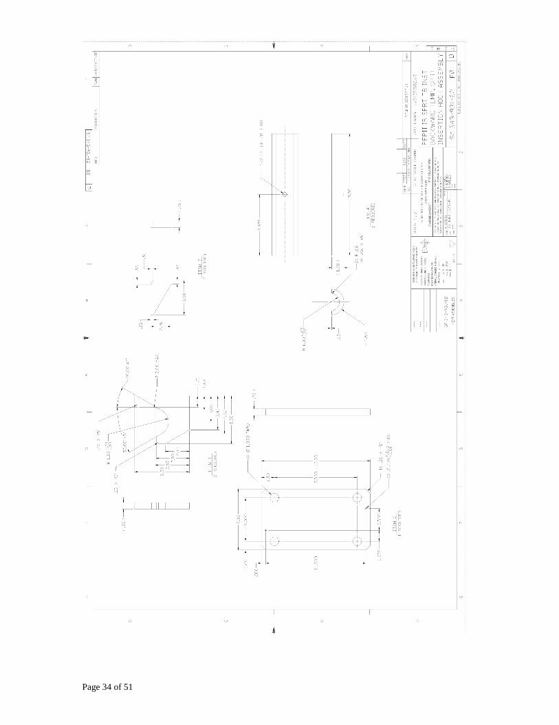
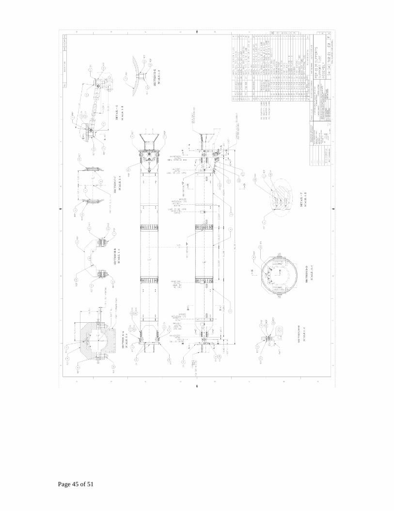
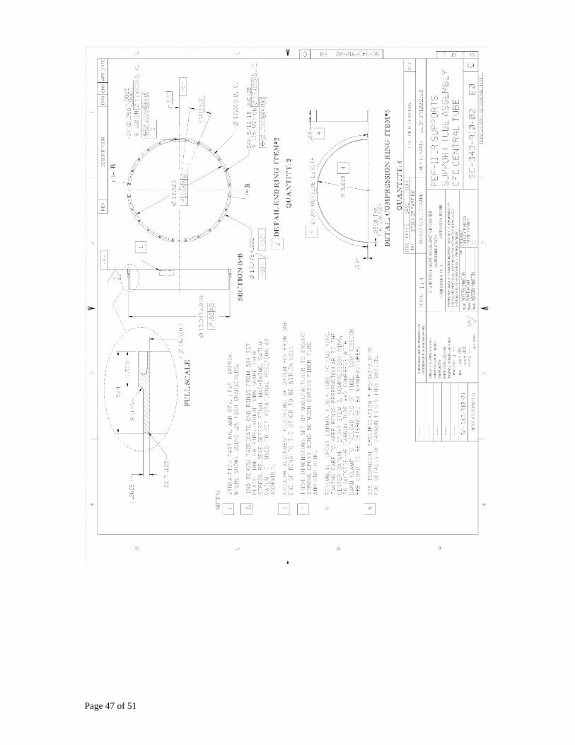
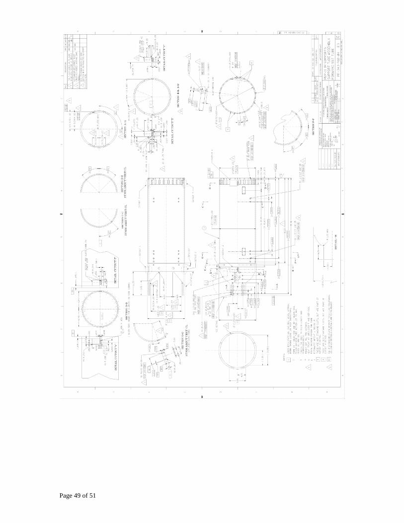
Appendix D Relative Drawings
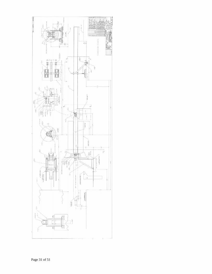
Page 31 of 51
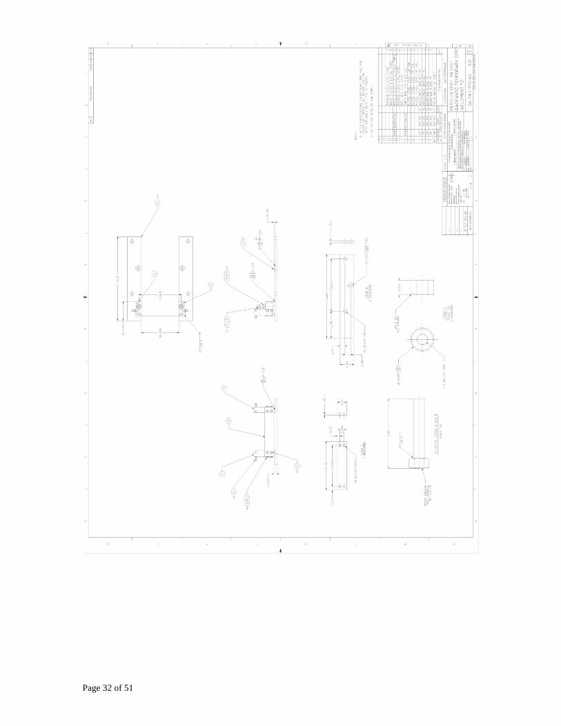
Page 32 of 51

Page 33 of 51
Page 34 of 51

Page 35 of 51

Page 36 of 51

Page 37 of 51

Page 38 of 51

Page 39 of 51
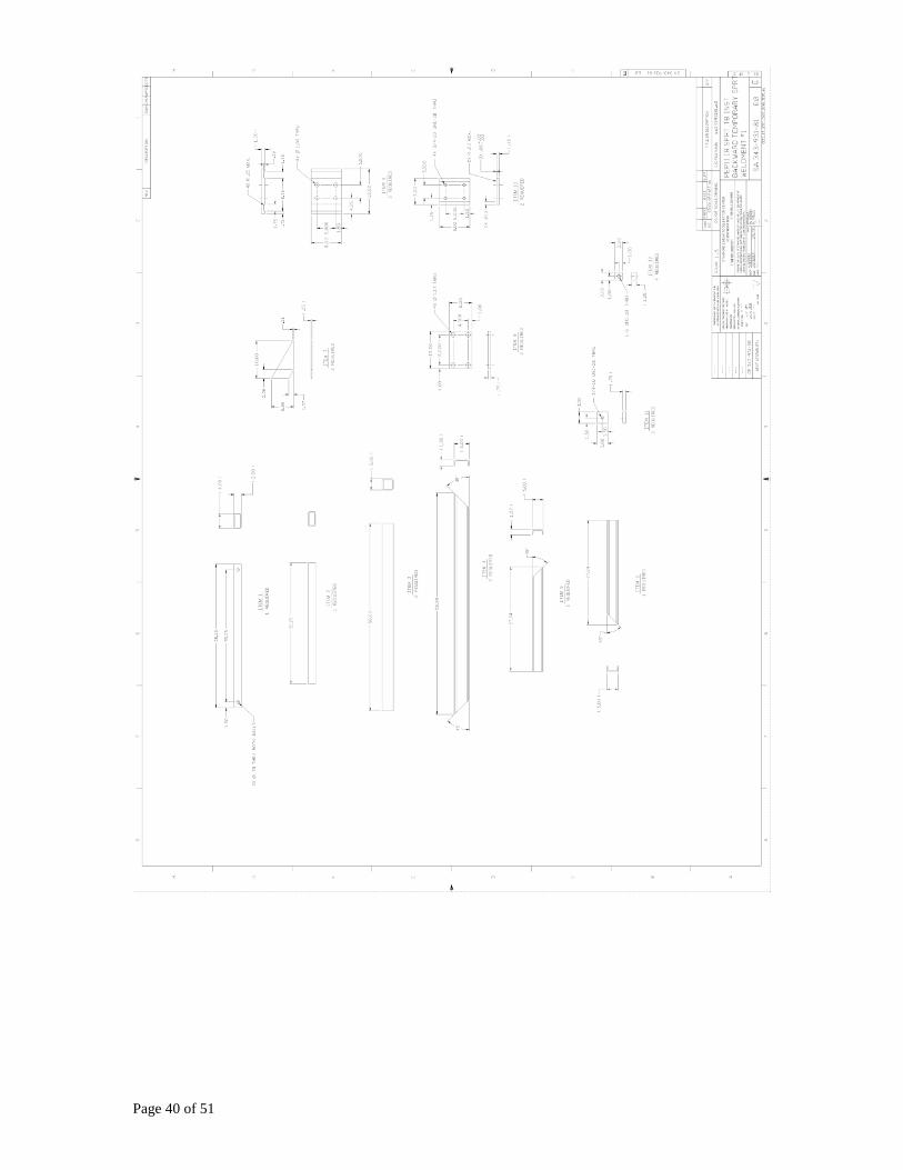
Page 40 of 51

Page 41 of 51

Page 42 of 51

Page 43 of 51

Page 44 of 51
Page 45 of 51

Page 46 of 51
Page 47 of 51

Page 48 of 51
Page 49 of 51

Page 50 of 51

Page 51 of 51