sustainable building technology - boston …bostonheatingsupply.com/rehau/rehau product...
TRANSCRIPT

ConstructionAutomotive
Industry
www.rehau.com
SUSTAINABLE BUILDING TECHNOLOGYPRODUCT CATALOGEFFECTIVE JANUARY 1, 2014

2
SUSTAINABLE BUILDING TECHNOLOGYCHANNELING ENERGY AND WATER RESOURCES
What is sustainable building technology?Sustainable products address some of our world’s greatest challenges – rising energy costs, water shortages, decaying infrastructure. Not only mustthey conserve natural resources; they must also have a sustained impact on how we build.
Energy efficient. Cost effective. Easy to install. Reliable. And above all, comfortable. These are the targets for our sustainable solutions.
This catalog showcases REHAU’s extensive range of PEXa pipe and compression-sleeve fitting solutions.
Whether you’re a contractor doing your first radiant heating or geothermal job or a seasoned pro bid-ding on a large commercial radiant heating/cooling project, REHAU’s industry-leading systems and services will help you get the best results.
REHAU produces PEXa pipe in Cullman, Alabama using a quality management system certified to the latest ISO 9001 standard.
3
Table of Contents SectionRadiant Heating and Snow and Ice Melting Systems .............................................................................. 1Energy Transfer Piping Systems ............................................................................................................ 2RAUGEO™ Ground Loop Heat Exchange Systems................................................................................... 3RAUPEX® Pipe for Plumbing ................................................................................................................ 4
Front cover:Developed as a model that can be replicated in communities throughout the United States, Sweetwater Spectrum provides a sup-ported living community designed for the unique needs of autistic adults. The residential community, completed in 2012, was de-signed to help residents establish a familiar, comfortable and manageable environment that would also nurture their independence. A REHAU radiant heating and cooling system helps control the sensory aspects of the living environment by providing a quiet, com-fortable, high-efficiency HVAC system in the four 3,240 sq foot residences and 2,300 sq ft community center. Read the complete project profile at www.na.rehau.com/sweetwater REHAU products used: RAUPEX® O
2 Barrier PEXa pipe, INSULPEX® energy transfer pipe and PRO-BALANCE® manifolds.

4
PROFESSIONAL SERVICESSUPPLEmENT YOUR CAPACITY. BROADEN YOUR ExPERTISE.
REHAU AcademyLearn from the company with more than four decades of experience in the PEXa business.www.na.rehau.com/academy
REHAU EDGESM
Our premier contractor development program re-wards you with training, design services, products, tools and networking events.www.na.rehau.com/edge
Promotional ProgramAds, point-of-sale materials and merchandise help you sell REHAU systems.www.na.rehau.com/dealermaterial
Technical SupportApplications engineers address questions about code compliance, installation techniques and unique jobsite challenges.Contact your REHAU representative
Design ServicesSystem designers support you with calculations and layouts for your next PEXa project.www.na.rehau.com/design
Website ResourcesIn our Resource Center, you will find all of our litera-ture, technical manuals, submittals and reference projects.www.na.rehau.com/resourcecenter
Design SoftwareREHAU LoopCAD® design software allows users to design radiant floor heating and snow and ice melting systems.www.na.rehau.com/loopcaddesign

radiant heating and snow and ice melting sYstemsproduct catalogeffective JanuarY 1, 2014
RH a
nd S
IM
ENERGYEFFICIENCY
1.2
RH a
nd S
IM
r�
1. RAUPEX® O2 Barrier Pipe . . . . . . . . . . . . . . . . . . . . . . . . . . . 1.3
2. Radiant Heating Plate Systems . . . . . . . . . . . . . . . . . . . . . . 1.5
3. Radiant Heating Panel Systems. . . . . . . . . . . . . . . . . . . . . . 1.6
4. Radiant Heating Mat Systems . . . . . . . . . . . . . . . . . . . . . . . 1.7
5. PRO-BALANCE® 1 in. Brass Manifold. . . . . . . . . . . . . . . . . . 1.8
6. PRO-BALANCE 1 1/4 in. Brass Manifold . . . . . . . . . . . . . . . 1.9
7. PRO-BALANCE Brass Manifolds –
Accessories and Replacement Parts . . . . . . . . . . . . . . . . . 1.10
8. REHAU Smart Controls . . . . . . . . . . . . . . . . . . . . . . . . . . . . 1.17
9. Zone Controls and Thermostats. . . . . . . . . . . . . . . . . . . . . 1.21
10. EVERLOC® Fittings . . . . . . . . . . . . . . . . . . . . . . . . . . . . . . 1.26
table of contents
11. RAUPEX Compression Nut Fittings . . . . . . . . . . . . . . . . . 1.31
12. EVERLOC Ball Valves . . . . . . . . . . . . . . . . . . . . . . . . . . . . 1.32
13. Compression Nut Ball Valves . . . . . . . . . . . . . . . . . . . . . . 1.33
14. Copper Manifolds. . . . . . . . . . . . . . . . . . . . . . . . . . . . . . . 1.34
15. Copper-EVERLOC Manifolds. . . . . . . . . . . . . . . . . . . . . . . 1.35
16. Installation Accessories. . . . . . . . . . . . . . . . . . . . . . . . . . 1.36
17. RAUTOOL™ PEX Pipe Installation Tools . . . . . . . . . . . . . . 1.40
18. Electronic Controls . . . . . . . . . . . . . . . . . . . . . . . . . . . . . 1.46
19. Mixing Valves. . . . . . . . . . . . . . . . . . . . . . . . . . . . . . . . . . 1.48
20. Hydronic Accessories . . . . . . . . . . . . . . . . . . . . . . . . . . . 1.51
For updates to this publication and the most current technical instructions, safety information and manufacturer’s recommendations, visit na.rehau.com/resourcecenter
RH a
nd S
IM
1.3
RH a
nd S
IM
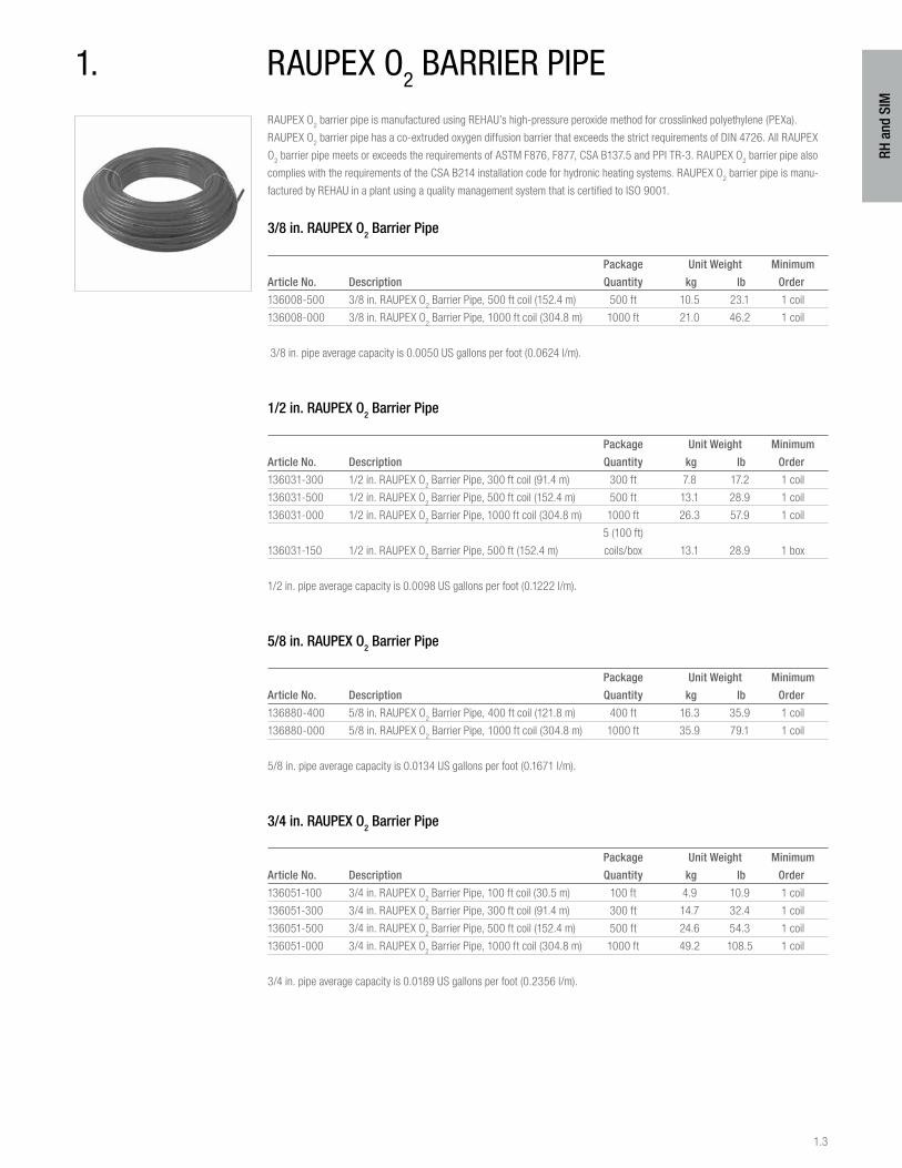
RAUPEX O2 barrier pipe is manufactured using REHAU’s high-pressure peroxide method for crosslinked polyethylene (PEXa).
RAUPEX O2 barrier pipe has a co-extruded oxygen diffusion barrier that exceeds the strict requirements of DIN 4726. All RAUPEX
O2 barrier pipe meets or exceeds the requirements of ASTM F876, F877, CSA B137.5 and PPI TR-3. RAUPEX O
2 barrier pipe also
complies with the requirements of the CSA B214 installation code for hydronic heating systems. RAUPEX O2 barrier pipe is manu-
factured by REHAU in a plant using a quality management system that is certified to ISO 9001.
3/8 in. RAUPEX O2 Barrier Pipe
Package Unit Weight Minimum
Article No. Description Quantity kg lb Order
136008-500 3/8 in. RAUPEX O2 Barrier Pipe, 500 ft coil (152.4 m) 500 ft 10.5 23.1 1 coil
136008-000 3/8 in. RAUPEX O2 Barrier Pipe, 1000 ft coil (304.8 m) 1000 ft 21.0 46.2 1 coil
3/8 in. pipe average capacity is 0.0050 US gallons per foot (0.0624 l/m).
1/2 in. RAUPEX O2 Barrier Pipe
Package Unit Weight Minimum
Article No. Description Quantity kg lb Order
136031-300 1/2 in. RAUPEX O2 Barrier Pipe, 300 ft coil (91.4 m) 300 ft 7.8 17.2 1 coil
136031-500 1/2 in. RAUPEX O2 Barrier Pipe, 500 ft coil (152.4 m) 500 ft 13.1 28.9 1 coil
136031-000 1/2 in. RAUPEX O2 Barrier Pipe, 1000 ft coil (304.8 m) 1000 ft 26.3 57.9 1 coil
5 (100 ft)
136031-150 1/2 in. RAUPEX O2 Barrier Pipe, 500 ft (152.4 m) coils/box 13.1 28.9 1 box
1/2 in. pipe average capacity is 0.0098 US gallons per foot (0.1222 l/m).
5/8 in. RAUPEX O2 Barrier Pipe
Package Unit Weight Minimum
Article No. Description Quantity kg lb Order
136880-400 5/8 in. RAUPEX O2 Barrier Pipe, 400 ft coil (121.8 m) 400 ft 16.3 35.9 1 coil
136880-000 5/8 in. RAUPEX O2 Barrier Pipe, 1000 ft coil (304.8 m) 1000 ft 35.9 79.1 1 coil
5/8 in. pipe average capacity is 0.0134 US gallons per foot (0.1671 l/m).
3/4 in. RAUPEX O2 Barrier Pipe
Package Unit Weight Minimum
Article No. Description Quantity kg lb Order
136051-100 3/4 in. RAUPEX O2 Barrier Pipe, 100 ft coil (30.5 m) 100 ft 4.9 10.9 1 coil
136051-300 3/4 in. RAUPEX O2 Barrier Pipe, 300 ft coil (91.4 m) 300 ft 14.7 32.4 1 coil
136051-500 3/4 in. RAUPEX O2 Barrier Pipe, 500 ft coil (152.4 m) 500 ft 24.6 54.3 1 coil
136051-000 3/4 in. RAUPEX O2 Barrier Pipe, 1000 ft coil (304.8 m) 1000 ft 49.2 108.5 1 coil
3/4 in. pipe average capacity is 0.0189 US gallons per foot (0.2356 l/m).
1. raupeX o2 barrier pipe
1.4
RH a
nd S
IM
1 in. RAUPEX O2 Barrier Pipe
Package Unit Weight Minimum
Article No. Description Quantity kg lb Order
136011-100 1 in. RAUPEX O2 Barrier Pipe, 100 ft coil (30.5 m) 100 ft 7.9 17.5 1 coil
136011-500 1 in. RAUPEX O2 Barrier Pipe, 500 ft coil (152.4 m) 500 ft 39.7 87.5 1 coil
1 in. pipe average capacity is 0.0316 US gallons per foot (0.3939 l/m).
1 1/4 in. RAUPEX O2 Barrier Pipe
Package Unit Weight Minimum
Article No. Description Quantity kg lb Order
136283-100 1 1/4 in. RAUPEX O2 Barrier Pipe, 100 ft coil (30.5 m) 100 ft 11.4 25.0 1 coil
1 1/4 in. pipe average capacity is 0.0467 US gallons per foot (0.5827 l/m).
1 1/2 in. RAUPEX O2 Barrier Pipe
Package Unit Weight Minimum
Article No. Description Quantity kg lb Order
136293-100 1 1/2 in. RAUPEX O2 Barrier Pipe, 100 ft coil (30.5 m) 100 ft 16.0 35.0 1 coil
1 1/2 in. pipe average capacity is 0.0650 US gallons per foot (0.8118 l/m).
2 in. RAUPEX O2 Barrier Pipe
Package Unit Weight Minimum
Article No. Description Quantity kg lb Order
136303-100 2 in. RAUPEX O2 Barrier Pipe, 100 ft coil (30.5 m) 100 ft 27.4 60.0 1 coil
2 in. pipe average capacity is 0.1114 US gallons per foot (1.3906 l/m).
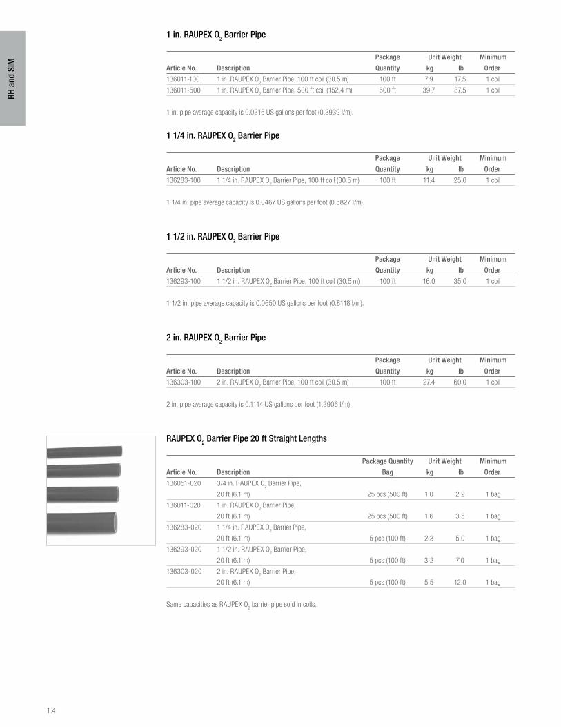
RAUPEX O2 Barrier Pipe 20 ft Straight Lengths
Package Quantity Unit Weight Minimum
Article No. Description Bag kg lb Order
136051-020 3/4 in. RAUPEX O2 Barrier Pipe,
20 ft (6.1 m) 25 pcs (500 ft) 1.0 2.2 1 bag
136011-020 1 in. RAUPEX O2 Barrier Pipe,
20 ft (6.1 m) 25 pcs (500 ft) 1.6 3.5 1 bag
136283-020 1 1/4 in. RAUPEX O2 Barrier Pipe,
20 ft (6.1 m) 5 pcs (100 ft) 2.3 5.0 1 bag
136293-020 1 1/2 in. RAUPEX O2 Barrier Pipe,
20 ft (6.1 m) 5 pcs (100 ft) 3.2 7.0 1 bag
136303-020 2 in. RAUPEX O2 Barrier Pipe,
20 ft (6.1 m) 5 pcs (100 ft) 5.5 12.0 1 bag
Same capacities as RAUPEX O2 barrier pipe sold in coils.
1.5
RH a
nd S
IM
2. radiant heating plate sYstems
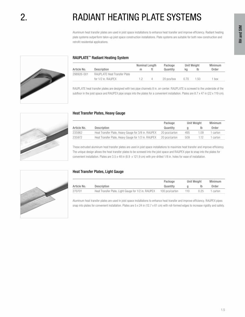
Nominal Length Package Unit Weight MinimumArticle No. Description m ft Quantity kg lb Order
298926-001 RAUPLATE Heat Transfer Plate
for 1/2 in. RAUPEX 1.2 4 20 pcs/box 0.70 1.50 1 box
RAUPLATE heat transfer plates are designed with two pipe channels 8 in. on-center. RAUPLATE is screwed to the underside of the
subfloor in the joist space and RAUPEX pipe snaps into the plates for a convenient installation. Plates are 8.7 x 47 in (22 x 119 cm).
Heat Transfer Plates, Heavy Gauge
Package Unit Weight Minimum
Article No. Description Quantity g lb Order
235962 Heat Transfer Plate, Heavy Gauge for 3/8 in. RAUPEX 20 pcs/carton 495 1.09 1 carton
235972 Heat Transfer Plate, Heavy Gauge for 1/2 in. RAUPEX 20 pcs/carton 509 1.12 1 carton
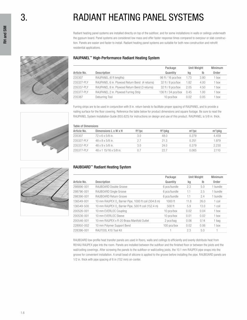
These extruded aluminum heat transfer plates are used in joist space installations to maximize heat transfer and improve efficiency.
The unique design allows the heat transfer plates to be screwed into the joist space and RAUPEX pipe to snap into the plates for
convenient installation. Plates are 3.5 x 48 in (8.9 x 121.9 cm) with pre-drilled 1/8 in. holes for ease of installation.
Heat Transfer Plates, Light Gauge
Package Unit Weight Minimum
Article No. Description Quantity g lb Order
270701 Heat Transfer Plate, Light Gauge for 1/2 in. RAUPEX 100 pcs/carton 110 0.25 1 carton
Aluminum heat transfer plates are used in joist space installations to enhance heat transfer and improve efficiency. RAUPEX pipes
snap into plates for convenient installation. Plates are 5 x 24 in (12.7 x 61 cm) with roll-formed edges to increase rigidity and safety.
Aluminum heat transfer plates are used in joist space installations to enhance heat transfer and improve efficiency. Radiant heating
plate systems outperform talon-up joist space construction installations. Plate systems are suitable for both new construction and
retrofit residential applications.
RAUPLATE™ Radiant Heating System
1.6
RH a
nd S
IM
Radiant heating panel systems are installed directly on top of the subfloor, and for some installations in walls or ceilings underneath
the gypsum board. Panel systems are considered low mass and offer faster response times compared to overpour or slab construc-
tion. Panels are easier and faster to install. Radiant heating panel systems are suitable for both new construction and retrofit
residential applications.
RAUPANEL™ High-Performance Radiant Heating System
Package Unit Weight Minimum
Article No. Description Quantity kg lb Order
235307 RAUPANEL (6 ft lengths) 96 ft / 16 pcs/box 1.73 3.80 1 box
235327-PLY RAUPANEL 6 in. Plywood Return Bend (4 returns) 32 ft / 8 pcs/box 1.82 4.00 1 box
235337-PLY RAUPANEL 8 in. Plywood Return Bend (3 returns) 32 ft / 8 pcs/box 2.05 4.50 1 box
235377-PLY RAUPANEL 2 in. Plywood Furring Strip 136 ft / 34 pcs/box 0.45 1.00 1 box
235387 Deburring Tool 10 pcs/box 0.02 0.05 1 box
Furring strips are to be used in conjunction with 8 in. return bends to facilitate proper spacing of RAUPANEL and to provide a
nailing surface for the floor covering. Reference the table below for product dimensions and square footage. Be sure to read the
RAUPANEL System Installation Guide (855.625) for instructions on design and use of this product. RAUPANEL is 5/8 in. thick.
Table of Dimensions
Article No. Dimensions L x W x H ft2/pc ft2/pkg m2/pc m2/pkg
235307 72 x 6 x 5/8 in. 3.0 48.0 0.279 4.459
235327-PLY 48 x 8 x 5/8 in. 2.7 21.3 0.251 1.979
235337-PLY 48 x 9 x 5/8 in. 3.0 24.0 0.279 2.230
235377-PLY 48 x 1 15/16 x 5/8 in. 0.7 22.7 0.065 2.110
RAUBOARD™ Radiant Heating System
Package Unit Weight Minimum
Article No. Description Quantity kg lb Order
298896-001 RAUBOARD Double Groove 6 pcs/bundle 2.3 5.0 1 bundle
298796-001 RAUBOARD Single Groove 6 pcs/bundle 1.1 2.5 1 bundle
298396-001 RAUBOARD Return Groove 6 pcs/bundle 1.1 2.4 1 bundle
136549-001 10 mm RAUPEX O2 Barrier Pipe, 1000 ft coil (304.8 m) 1000 ft 11.8 26.0 1 coil
136549-500 10 mm RAUPEX O2 Barrier Pipe, 500 ft coil (152.4 m) 500 ft 5.9 13.0 1 coil
200526-001 10 mm EVERLOC Coupling 10 pcs/box 0.02 0.04 1 box
200536-001 10 mm EVERLOC Sleeve 10 pcs/box 0.01 0.02 1 box
200546-001 10 mm RAUPEX x R-20 Brass Manifold Outlet 2 pcs/bag 0.06 0.14 1 bag
228950-002 10 mm Polymer Support Bend 100 pcs/box 0.02 0.06 1 box
228396-001 RAUTOOL K10 Tool Kit 1 2.3 5.0 1
RAUBOARD low-profile heat transfer panels are used in floors, walls and ceilings to efficiently and evenly distribute heat from
REHAU RAUPEX pipe into the room. Panels are installed between the subfloor and the finished floor or between the joists and the
wall/ceiling coverings. After screwing the panels to the subfloor or wall/ceiling joists, the 10.1 mm RAUPEX pipe snaps into the
groove for convenient installation. A small bead of silicone is applied to the groove before installing the pipe. RAUBOARD panels are
1/2 in. thick with pipe spacing of 6 in (152 mm) on-center.
3. radiant heating panel sYstems
1.7
RH a
nd S
IM
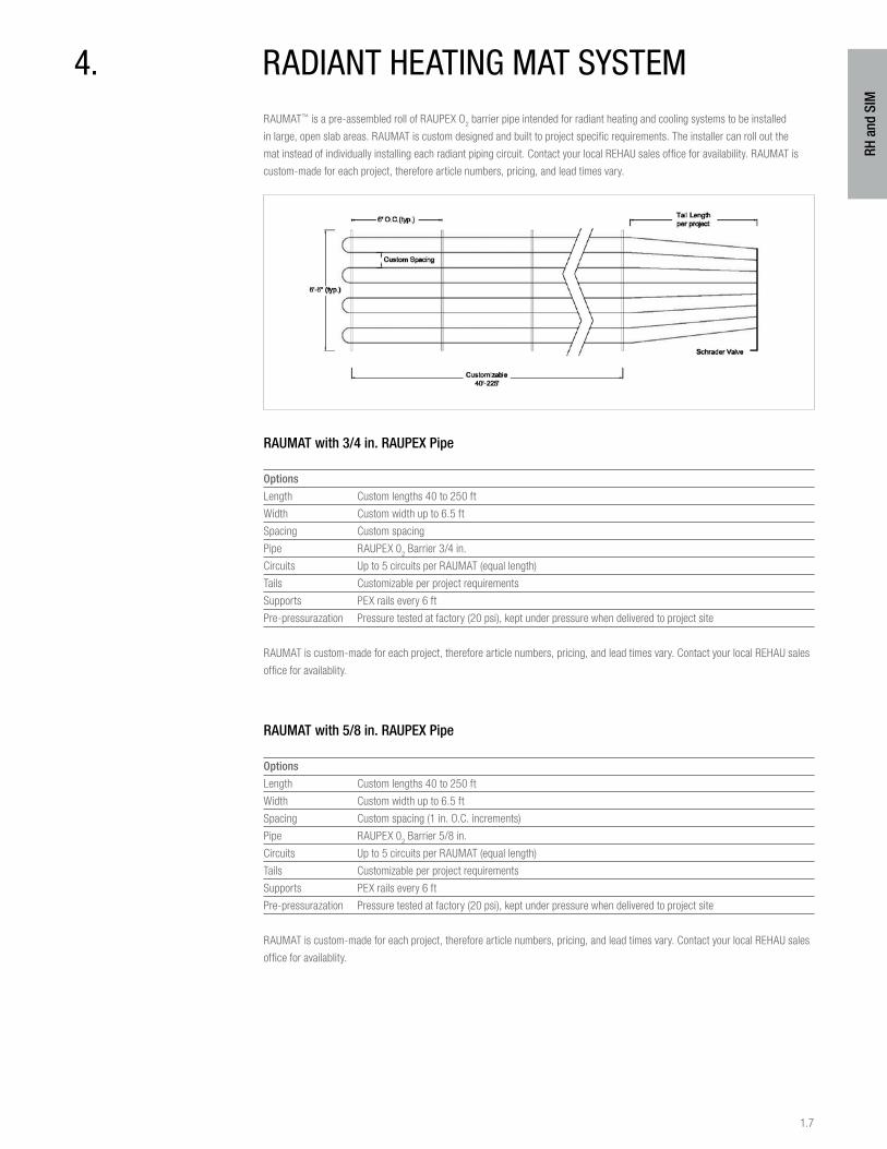
4. radiant heating mat sYstemRAUMAT™ is a pre-assembled roll of RAUPEX O
2 barrier pipe intended for radiant heating and cooling systems to be installed
in large, open slab areas. RAUMAT is custom designed and built to project specific requirements. The installer can roll out the
mat instead of individually installing each radiant piping circuit. Contact your local REHAU sales office for availability. RAUMAT is
custom-made for each project, therefore article numbers, pricing, and lead times vary.
RAUMAT with 3/4 in. RAUPEX Pipe
Options
Length Custom lengths 40 to 250 ft
Width Custom width up to 6.5 ft
Spacing Custom spacing
Pipe RAUPEX 02 Barrier 3/4 in.
Circuits Up to 5 circuits per RAUMAT (equal length)
Tails Customizable per project requirements
Supports PEX rails every 6 ft
Pre-pressurazation Pressure tested at factory (20 psi), kept under pressure when delivered to project site
RAUMAT is custom-made for each project, therefore article numbers, pricing, and lead times vary. Contact your local REHAU sales
office for availablity.
RAUMAT with 5/8 in. RAUPEX Pipe
Options
Length Custom lengths 40 to 250 ft
Width Custom width up to 6.5 ft
Spacing Custom spacing (1 in. O.C. increments)
Pipe RAUPEX 02 Barrier 5/8 in.
Circuits Up to 5 circuits per RAUMAT (equal length)
Tails Customizable per project requirements
Supports PEX rails every 6 ft
Pre-pressurazation Pressure tested at factory (20 psi), kept under pressure when delivered to project site
RAUMAT is custom-made for each project, therefore article numbers, pricing, and lead times vary. Contact your local REHAU sales
office for availablity.
1.8
RH a
nd S
IM
5. pro-balance 1 in. brass manifold
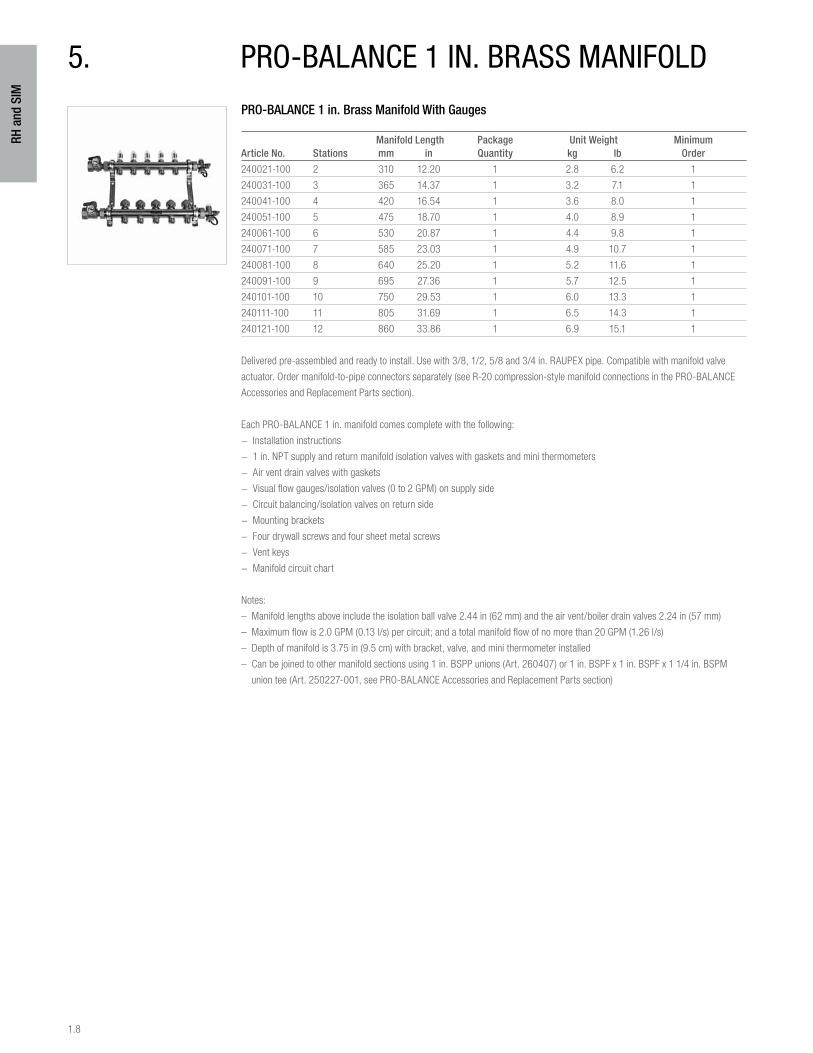
PRO-BALANCE 1 in. Brass Manifold With Gauges
Manifold Length Package Unit Weight MinimumArticle No. Stations mm in Quantity kg lb Order
240021-100 2 310 12.20 1 2.8 6.2 1
240031-100 3 365 14.37 1 3.2 7.1 1
240041-100 4 420 16.54 1 3.6 8.0 1
240051-100 5 475 18.70 1 4.0 8.9 1
240061-100 6 530 20.87 1 4.4 9.8 1
240071-100 7 585 23.03 1 4.9 10.7 1
240081-100 8 640 25.20 1 5.2 11.6 1
240091-100 9 695 27.36 1 5.7 12.5 1
240101-100 10 750 29.53 1 6.0 13.3 1
240111-100 11 805 31.69 1 6.5 14.3 1
240121-100 12 860 33.86 1 6.9 15.1 1
Delivered pre-assembled and ready to install. Use with 3/8, 1/2, 5/8 and 3/4 in. RAUPEX pipe. Compatible with manifold valve
actuator. Order manifold-to-pipe connectors separately (see R-20 compression-style manifold connections in the PRO-BALANCE
Accessories and Replacement Parts section).
Each PRO-BALANCE 1 in. manifold comes complete with the following:
− Installation instructions
− 1 in. NPT supply and return manifold isolation valves with gaskets and mini thermometers
− Air vent drain valves with gaskets
− Visual flow gauges/isolation valves (0 to 2 GPM) on supply side
− Circuit balancing/isolation valves on return side
− Mounting brackets
− Four drywall screws and four sheet metal screws
− Vent keys
− Manifold circuit chart
Notes:
– Manifold lengths above include the isolation ball valve 2.44 in (62 mm) and the air vent/boiler drain valves 2.24 in (57 mm)
– Maximum flow is 2.0 GPM (0.13 l/s) per circuit; and a total manifold flow of no more than 20 GPM (1.26 l/s)
– Depth of manifold is 3.75 in (9.5 cm) with bracket, valve, and mini thermometer installed
– Can be joined to other manifold sections using 1 in. BSPP unions (Art. 260407) or 1 in. BSPF x 1 in. BSPF x 1 1/4 in. BSPM
union tee (Art. 250227-001, see PRO-BALANCE Accessories and Replacement Parts section)
1.9
RH a
nd S
IM
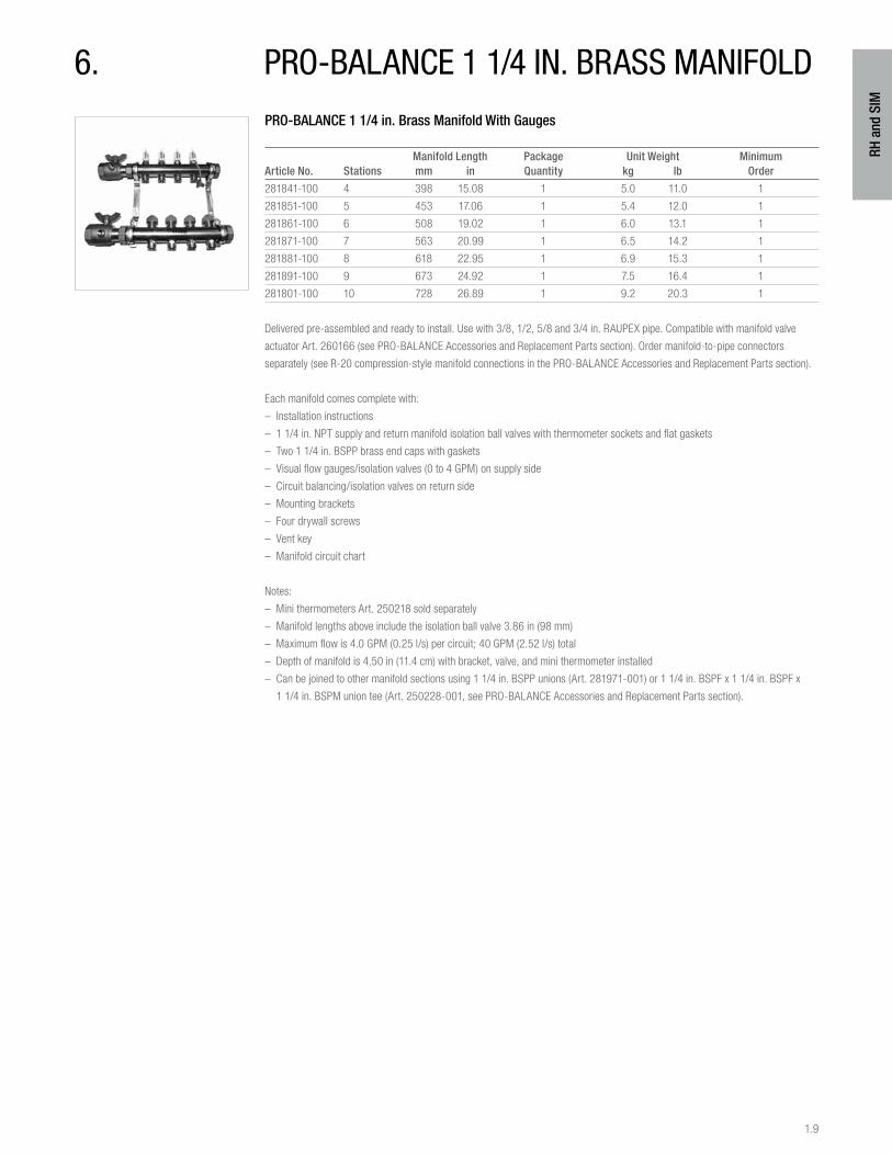
PRO-BALANCE 1 1/4 in. Brass Manifold With Gauges
Manifold Length Package Unit Weight MinimumArticle No. Stations mm in Quantity kg lb Order
281841-100 4 398 15.08 1 5.0 11.0 1
281851-100 5 453 17.06 1 5.4 12.0 1
281861-100 6 508 19.02 1 6.0 13.1 1
281871-100 7 563 20.99 1 6.5 14.2 1
281881-100 8 618 22.95 1 6.9 15.3 1
281891-100 9 673 24.92 1 7.5 16.4 1
281801-100 10 728 26.89 1 9.2 20.3 1
Delivered pre-assembled and ready to install. Use with 3/8, 1/2, 5/8 and 3/4 in. RAUPEX pipe. Compatible with manifold valve
actuator Art. 260166 (see PRO-BALANCE Accessories and Replacement Parts section). Order manifold-to-pipe connectors
separately (see R-20 compression-style manifold connections in the PRO-BALANCE Accessories and Replacement Parts section).
Each manifold comes complete with:
– Installation instructions
– 1 1/4 in. NPT supply and return manifold isolation ball valves with thermometer sockets and flat gaskets
– Two 1 1/4 in. BSPP brass end caps with gaskets
– Visual flow gauges/isolation valves (0 to 4 GPM) on supply side
– Circuit balancing/isolation valves on return side
– Mounting brackets
– Four drywall screws
– Vent key
– Manifold circuit chart
Notes:
– Mini thermometers Art. 250218 sold separately
– Manifold lengths above include the isolation ball valve 3.86 in (98 mm)
– Maximum flow is 4.0 GPM (0.25 l/s) per circuit; 40 GPM (2.52 l/s) total
– Depth of manifold is 4.50 in (11.4 cm) with bracket, valve, and mini thermometer installed
– Can be joined to other manifold sections using 1 1/4 in. BSPP unions (Art. 281971-001) or 1 1/4 in. BSPF x 1 1/4 in. BSPF x
1 1/4 in. BSPM union tee (Art. 250228-001, see PRO-BALANCE Accessories and Replacement Parts section).
6. pro-balance 1 1/4 in. brass manifold
1.10
RH a
nd S
IM
7. pro-balance brass manifolds – accessories and replacement parts
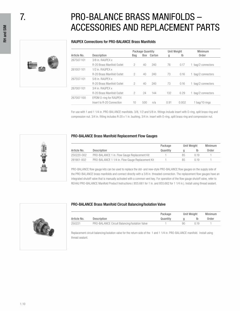
RAUPEX Connections for PRO-BALANCE Brass Manifolds
Package Quantity Unit Weight MinimumArticle No. Description Bag Box Carton g lb Order
267507-101 3/8 in. RAUPEX x
R-20 Brass Manifold Outlet 2 40 240 76 0.17 1 bag/2 connectors
261007-101 1/2 in. RAUPEX x
R-20 Brass Manifold Outlet 2 40 240 73 0.16 1 bag/2 connectors
267557-101 5/8 in. RAUPEX x
R-20 Brass Manifold Outlet 2 40 240 73 0.16 1 bag/2 connectors
267007-101 3/4 in. RAUPEX x
R-20 Brass Manifold Outlet 2 24 144 132 0.29 1 bag/2 connectors
267007-100 EPDM O-ring for RAUPEX
Insert to R-20 Connection 10 500 n/a 0.91 0.002 1 bag/10 rings
For use with 1 and 1 1/4 in. PRO-BALANCE manifolds. 3/8, 1/2 and 5/8 in. fittings include insert with O-ring, split brass ring and
compression nut. 3/4 in. fitting includes R-20 x 1 in. bushing, 3/4 in. insert with O-ring, split brass ring and compression nut.
PRO-BALANCE Brass Manifold Replacement Flow Gauges
Package Unit Weight Minimum
Article No. Description Quantity g lb Order
250220-002 PRO-BALANCE 1 in. Flow Gauge Replacement Kit 1 85 0.19 1
281901-002 PRO-BALANCE 1 1/4 in. Flow Gauge Replacement Kit 1 85 0.19 1
PRO-BALANCE flow gauge kits can be used to replace the old- and new-style PRO-BALANCE flow gauges on the supply side of
the PRO-BALANCE brass manifolds and connect directly with a 3/8 in. threaded connection. The replacement flow gauges have an
integrated shutoff valve that is manually activated with a common vent key. For operation of the flow gauge shutoff valve, refer to
REHAU PRO-BALANCE Manifold Product Instructions ( 855.661 for 1 in. and 855.662 for 1 1/4 in.). Install using thread sealant.
PRO-BALANCE Brass Manifold Circuit Balancing/Isolation Valve
Package Unit Weight Minimum
Article No. Description Quantity g lb Order
250221 PRO-BALANCE Circuit Balancing/Isolation Valve 1 90 0.19 1
Replacement circuit balancing/isolation valve for the return side of the 1 and 1 1/4 in. PRO-BALANCE manifold. Install using
thread sealant.

1.11
RH a
nd S
IM
PRO-BALANCE Brass Manifold Flow Setter Valves
Package Unit Weight Minimum
Article No. Description Quantity g lb Order
244807-001 1/2 to 4 GPM PRO-BALANCE Flow Setter Valve 1 760 1.67 1
244817-001 1 to 9 GPM PRO-BALANCE Flow Setter Valve 1 760 1.67 1
PRO-BALANCE flow setter valves are used to set flow to PRO-BALANCE 1 in. manifolds and can be installed in-line into any pipe
feeding a manifold. This is ideal when multiple manifolds are fed from a single circulator and flow needs to be set correctly to each.
PRO-BALANCE flow setter valves are also used in variable speed injection pump mixing systems to set the flow through the
injection loop.
PRO-BALANCE flow setter valves are supplied with two gaskets and adapters converting to 1 in. MPT.
PRO-BALANCE Brass Manifold Flow-Stop Circuit Valve
Package Unit Weight Minimum
Article No. Description Quantity kg lb Order
250224 PRO-BALANCE Flow-Stop Circuit Valve 5/box 0.12 0.26 1 box
This brass 1/4 turn ball valve attaches to R-20 circuit outlets on the supply side of 1 and 1 1/4 in. PRO-BALANCE manifolds to
allow for complete shut-off. Standard 1/4 in. vent key (supplied with each manifold) is used to operate the valve. Install flow-stop
valves by hand onto R-20 outlets of the PRO-BALANCE 1 in. manifold. Do not use thread sealant. Thread the valve clockwise until it
stops. If necessary, back the valve off to align the valve stem with the front of the manifold.
NPT Valve Set with Thermometer Housings for PRO-BALANCE 1 in. Brass Manifold
Package Unit Weight Minimum
Article No. Description Quantity g lb Order
250216 1 in. NPT Valve Set w/ Thermometer Housings Set of 2 420 0.92 1 set
These valves have integrated thermometer housings on each side of the valve bodies. Mini thermometers (Art. 250218) can be set
into these housings to give accurate readings of temperatures on both supply and return sides of any PRO-BALANCE 1 in. manifold.
Includes gaskets. Mini thermometers are sold separately.
PRO-BALANCE 1 1/4 in. Brass Manifold NPT Isolation Ball Valve Set
Package Unit Weight Minimum
Article No. Description Quantity kg lb Order
281931-001 1 1/4 in. NPT Isolation Valve Set w/ Gaskets 1 set of 2 2.1 4.63 1 set
These valves have integrated thermometer housings on each side of the valve bodies. Mini thermometers (Art. 250218) can be
set into these housings to give accurate readings of temperatures on both supply and return sides of any PRO-BALANCE 1 1/4 in.
manifold. Includes gaskets. Mini thermometers are sold separately.
1.12
RH a
nd S
IM
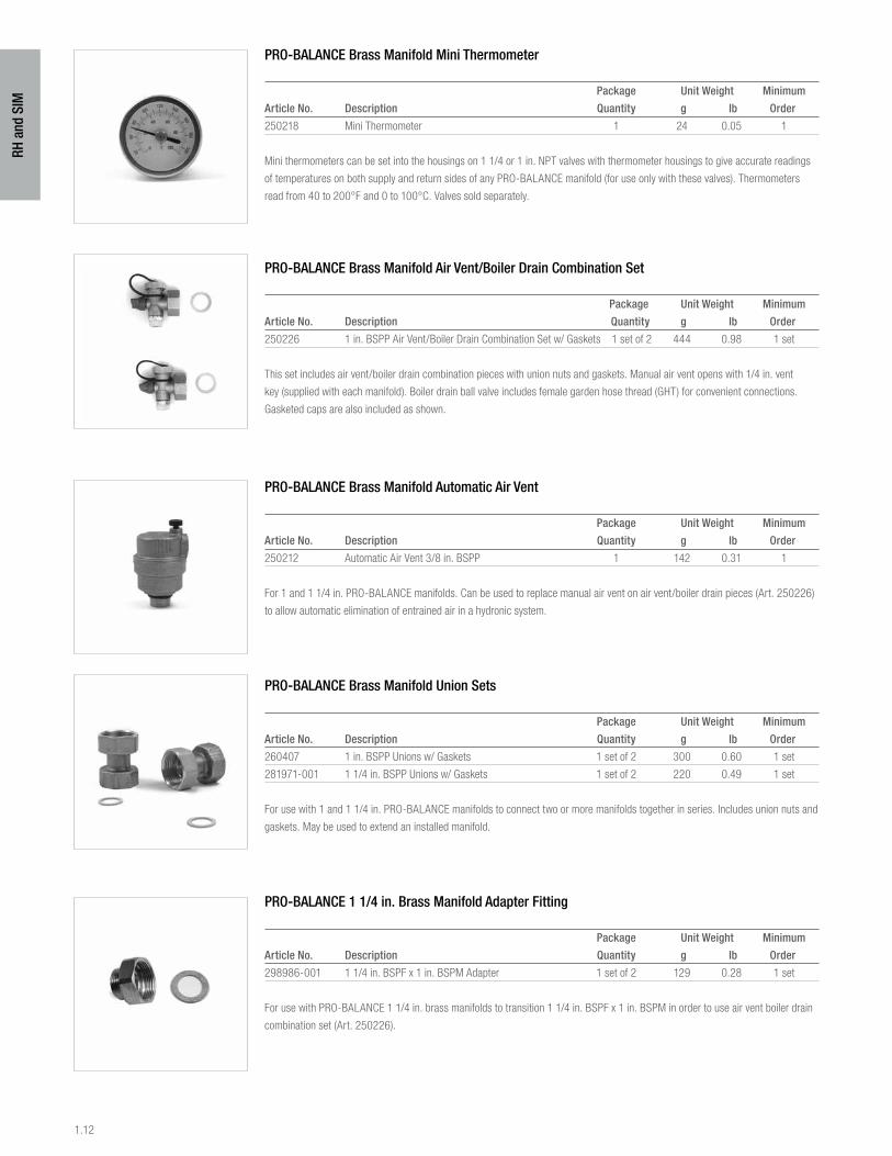
PRO-BALANCE Brass Manifold Mini Thermometer
Package Unit Weight Minimum
Article No. Description Quantity g lb Order
250218 Mini Thermometer 1 24 0.05 1
Mini thermometers can be set into the housings on 1 1/4 or 1 in. NPT valves with thermometer housings to give accurate readings
of temperatures on both supply and return sides of any PRO-BALANCE manifold (for use only with these valves). Thermometers
read from 40 to 200°F and 0 to 100°C. Valves sold separately.
PRO-BALANCE Brass Manifold Air Vent/Boiler Drain Combination Set
Package Unit Weight Minimum
Article No. Description Quantity g lb Order
250226 1 in. BSPP Air Vent/Boiler Drain Combination Set w/ Gaskets 1 set of 2 444 0.98 1 set
This set includes air vent/boiler drain combination pieces with union nuts and gaskets. Manual air vent opens with 1/4 in. vent
key (supplied with each manifold). Boiler drain ball valve includes female garden hose thread (GHT) for convenient connections.
Gasketed caps are also included as shown.
PRO-BALANCE Brass Manifold Automatic Air Vent
Package Unit Weight Minimum
Article No. Description Quantity g lb Order
250212 Automatic Air Vent 3/8 in. BSPP 1 142 0.31 1
For 1 and 1 1/4 in. PRO-BALANCE manifolds. Can be used to replace manual air vent on air vent/boiler drain pieces (Art. 250226)
to allow automatic elimination of entrained air in a hydronic system.
PRO-BALANCE Brass Manifold Union Sets
Package Unit Weight Minimum
Article No. Description Quantity g lb Order
260407 1 in. BSPP Unions w/ Gaskets 1 set of 2 300 0.60 1 set
281971-001 1 1/4 in. BSPP Unions w/ Gaskets 1 set of 2 220 0.49 1 set
For use with 1 and 1 1/4 in. PRO-BALANCE manifolds to connect two or more manifolds together in series. Includes union nuts and
gaskets. May be used to extend an installed manifold.
PRO-BALANCE 1 1/4 in. Brass Manifold Adapter Fitting
Package Unit Weight Minimum
Article No. Description Quantity g lb Order
298986-001 1 1/4 in. BSPF x 1 in. BSPM Adapter 1 set of 2 129 0.28 1 set
For use with PRO-BALANCE 1 1/4 in. brass manifolds to transition 1 1/4 in. BSPF x 1 in. BSPM in order to use air vent boiler drain
combination set (Art. 250226).

1.13
RH a
nd S
IM
PRO-BALANCE Brass Manifold Union Tee Sets
Package Unit Weight Minimum
Article No. Description Quantity kg lb Order
250227-001 1 in. BSPP Manifold Union Tee w/ Gaskets 1 set of 2 0.60 1.32 1 set
250228-001 1 1/4 in. BSPP Manifold Union Tee w/ Gaskets 1 set of 2 1.50 3.30 1 set
Supply side of 250227-001 is 1 1/4 in. BSPM. Supply side of 250228-001 is 1 1/4 in. BSPM. Sets are supplied with gaskets.
PRO-BALANCE Brass Manifold Circuit Outlet Cap
Package Unit Weight Minimum
Article No. Description Quantity g lb Order
250209-C R-20 Brass Circuit Outlet Cap w/ Gasket 1 28 0.07 1
Brass circuit outlet cap is used to cap off unused outlets on any 1 and 1 1/4 in. PRO-BALANCE manifold. Includes gasket.
PRO-BALANCE Brass Manifold End Caps
Package Unit Weight Minimum
Article No. Description Quantity g lb Order
250213 1 in. Brass Manifold End Cap w/ Gasket 1 100 0.22 1
281951-001 1 1/4 in. Manifold End Cap w/ Gasket 1 100 0.22 1
Can be used to cap off end of any manifold header while eliminating usual end pieces. Includes gasket.
PRO-BALANCE Brass Manifold BSPP 90° Angle Piece
Package Unit Weight Minimum
Article No. Description Quantity g lb Order
250214 1 in. BSPP 90° Angle Piece w/ Gasket 1 343 0.76 1
281981-001 1 1/4 in. BSPP 90° Angle Piece w/ Gasket 1 418 0.92 1
For 1 and 1 1/4 in. PRO-BALANCE manifolds. Includes union nut and gasket. Can be used to install manifold isolation valves at a
right angle to manifold.
PRO-BALANCE Brass Manifold Gaskets
Package Unit Weight Minimum
Article No. Description Quantity g lb Order
250203-G Gasket for 1 in. Manifold Valve 1 0.91 0.002 1
281811-001 Gasket for 1 1/4 in. Manifold Valve 1 2.30 0.005 1
1.14
RH a
nd S
IM
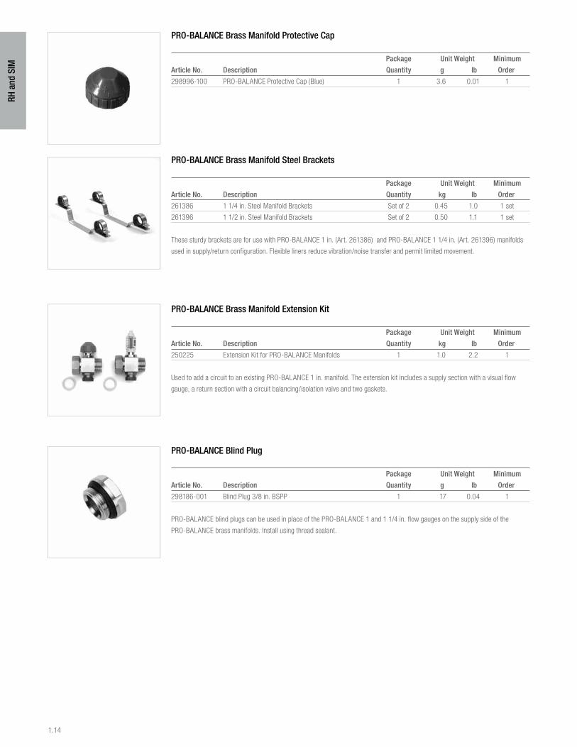
PRO-BALANCE Brass Manifold Protective Cap
Package Unit Weight Minimum
Article No. Description Quantity g lb Order
298996-100 PRO-BALANCE Protective Cap (Blue) 1 3.6 0.01 1
PRO-BALANCE Brass Manifold Steel Brackets
Package Unit Weight Minimum
Article No. Description Quantity kg lb Order
261386 1 1/4 in. Steel Manifold Brackets Set of 2 0.45 1.0 1 set
261396 1 1/2 in. Steel Manifold Brackets Set of 2 0.50 1.1 1 set
These sturdy brackets are for use with PRO-BALANCE 1 in. (Art. 261386) and PRO-BALANCE 1 1/4 in. (Art. 261396) manifolds
used in supply/return configuration. Flexible liners reduce vibration/noise transfer and permit limited movement.
PRO-BALANCE Brass Manifold Extension Kit
Package Unit Weight Minimum
Article No. Description Quantity kg lb Order
250225 Extension Kit for PRO-BALANCE Manifolds 1 1.0 2.2 1
Used to add a circuit to an existing PRO-BALANCE 1 in. manifold. The extension kit includes a supply section with a visual flow
gauge, a return section with a circuit balancing/isolation valve and two gaskets.
PRO-BALANCE Blind Plug
Package Unit Weight Minimum
Article No. Description Quantity g lb Order
298186-001 Blind Plug 3/8 in. BSPP 1 17 0.04 1
PRO-BALANCE blind plugs can be used in place of the PRO-BALANCE 1 and 1 1/4 in. flow gauges on the supply side of the
PRO-BALANCE brass manifolds. Install using thread sealant.
1.15
RH a
nd S
IM
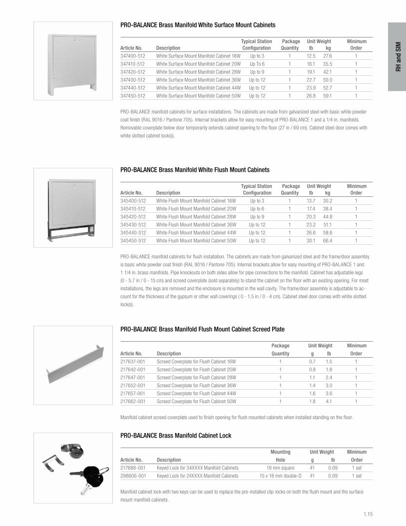
PRO-BALANCE Brass Manifold White Surface Mount Cabinets
Typical Station Package Unit Weight MinimumArticle No. Description Configuration Quantity lb kg Order
347400-512 White Surface Mount Manifold Cabinet 16W Up to 3 1 12.5 27.6 1
347410-512 White Surface Mount Manifold Cabinet 20W Up To 6 1 16.1 35.5 1
347420-512 White Surface Mount Manifold Cabinet 28W Up to 9 1 19.1 42.1 1
347430-512 White Surface Mount Manifold Cabinet 36W Up to 12 1 22.7 50.0 1
347440-512 White Surface Mount Manifold Cabinet 44W Up to 12 1 23.9 52.7 1
347450-512 White Surface Mount Manifold Cabinet 50W Up to 12 1 26.8 59.1 1
PRO-BALANCE manifold cabinets for surface installations. The cabinets are made from galvanized steel with basic white powder
coat finish (RAL 9016 / Pantone 705). Internal brackets allow for easy mounting of PRO-BALANCE 1 and a 1/4 in. manifolds.
Removable coverplate below door temporarily extends cabinet opening to the floor (27 in / 69 cm). Cabinet steel door comes with
white slotted cabinet lock(s).
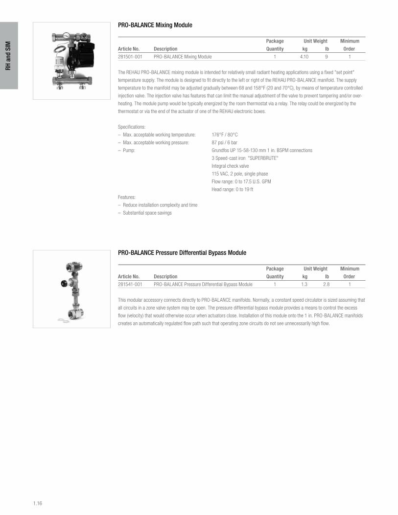
PRO-BALANCE Brass Manifold White Flush Mount Cabinets
Typical Station Package Unit Weight MinimumArticle No. Description Configuration Quantity lb kg Order
345400-512 White Flush Mount Manifold Cabinet 16W Up to 3 1 13.7 30.2 1
345410-512 White Flush Mount Manifold Cabinet 20W Up to 6 1 17.4 38.4 1
345420-512 White Flush Mount Manifold Cabinet 28W Up to 9 1 20.3 44.8 1
345430-512 White Flush Mount Manifold Cabinet 36W Up to 12 1 23.2 51.1 1
345440-512 White Flush Mount Manifold Cabinet 44W Up to 12 1 26.6 58.6 1
345450-512 White Flush Mount Manifold Cabinet 50W Up to 12 1 30.1 66.4 1
PRO-BALANCE manifold cabinets for flush installation. The cabinets are made from galvanized steel and the frame/door assembly
is basic white powder coat finish (RAL 9016 / Pantone 705). Internal brackets allow for easy mounting of PRO-BALANCE 1 and
1 1/4 in. brass manifolds. Pipe knockouts on both sides allow for pipe connections to the manifold. Cabinet has adjustable legs
(0 - 5.7 in / 0 - 15 cm) and screed coverplate (sold separately) to stand the cabinet on the floor with an existing opening. For most
installations, the legs are removed and the enclosure is mounted in the wall cavity. The frame/door assembly is adjustable to ac-
count for the thickness of the gypsum or other wall coverings ( 0 - 1.5 in / 0 - 4 cm). Cabinet steel door comes with white slotted
lock(s).
PRO-BALANCE Brass Manifold Flush Mount Cabinet Screed Plate
Package Unit Weight Minimum
Article No. Description Quantity g lb Order
217637-001 Screed Coverplate for Flush Cabinet 16W 1 0.7 1.5 1
217642-001 Screed Coverplate for Flush Cabinet 20W 1 0.8 1.8 1
217647-001 Screed Coverplate for Flush Cabinet 28W 1 1.1 2.4 1
217652-001 Screed Coverplate for Flush Cabinet 36W 1 1.4 3.0 1
217657-001 Screed Coverplate for Flush Cabinet 44W 1 1.6 3.6 1
217662-001 Screed Coverplate for Flush Cabinet 50W 1 1.8 4.1 1
Manifold cabinet screed coverplate used to finish opening for flush mounted cabinets when installed standing on the floor.
PRO-BALANCE Brass Manifold Cabinet Lock
Mounting Unit Weight Minimum
Article No. Description Hole g lb Order
217688-001 Keyed Lock for 34XXXX Manifold Cabinets 19 mm square 41 0.09 1 set
298606-001 Keyed Lock for 24XXXX Manifold Cabinets 15 x 18 mm double-D 41 0.09 1 set
Manifold cabinet lock with two keys can be used to replace the pre-installed clip-locks on both the flush mount and the surface
mount manifold cabinets.
1.16
RH a
nd S
IM
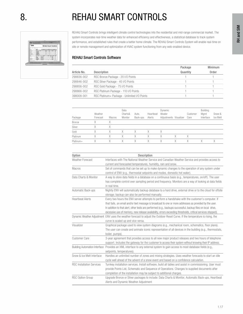
PRO-BALANCE Mixing Module
Package Unit Weight Minimum
Article No. Description Quantity kg lb Order
281501-001 PRO-BALANCE Mixing Module 1 4.10 9 1
The REHAU PRO-BALANCE mixing module is intended for relatively small radiant heating applications using a fixed "set point"
temperature supply. The module is designed to fit directly to the left or right of the REHAU PRO-BALANCE manifold. The supply
temperature to the manifold may be adjusted gradually between 68 and 158°F (20 and 70°C), by means of temperature controlled
injection valve. The injection valve has features that can limit the manual adjustment of the valve to prevent tampering and/or over-
heating. The module pump would be typically energized by the room thermostat via a relay. The relay could be energized by the
thermostat or via the end of the actuator of one of the REHAU electronic boxes.
Specifications:
– Max. acceptable working temperature: 176°F / 80°C
– Max. acceptable working pressure: 87 psi / 6 bar
– Pump: Grundfos UP 15-58-130 mm 1 in. BSPM connections
3 Speed-cast iron "SUPERBRUTE"
Integral check valve
115 VAC, 2 pole, single phase
Flow range: 0 to 17.5 U.S. GPM
Head range: 0 to 19 ft
Features:
– Reduce installation complexity and time
– Substantial space savings
PRO-BALANCE Pressure Differential Bypass Module
Package Unit Weight Minimum
Article No. Description Quantity kg lb Order
281541-001 PRO-BALANCE Pressure Differential Bypass Module 1 1.3 2.8 1
This modular accessory connects directly to PRO-BALANCE manifolds. Normally, a constant speed circulator is sized assuming that
all circuits in a zone valve system may be open. The pressure differential bypass module provides a means to control the excess
flow (velocity) that would otherwise occur when actuators close. Installation of this module onto the 1 in. PRO-BALANCE manifolds
creates an automatically regulated flow path such that operating zone circuits do not see unnecessarily high flow.
1.17
RH a
nd S
IM
REHAU Smart Controls brings intelligent climate control technologies into the residential and mid-range commercial market. The
system incorporates real-time weather data for enhanced efficiency and effectiveness, a statistical database to track system
performance, and established rules that create a better home climate. The REHAU Smart Controls System will enable real-time on
site or remote management and optimization of HVAC system functioning from any web-enabled device.
REHAU Smart Controls Software
Package Minimum
Article No. Description Quantity Order
298836-002 RSC Bronze Package - 20 I/O Points 1 1
298846-002 RSC Silver Package - 40 I/O Points 1 1
298856-002 RSC Gold Package - 75 I/O Points 1 1
298866-002 RSC Platinum Package - 110 I/O Points 1 1
398008-001 RSC Platinum+ Package - Unlimited I/O Points 1 1
Data Dynamic Building Weather Charts& Auto. Heartbeat Weater Customer Mgmt Snow & Package Forecast Macros Monitor Back-ups Alerts Adjustments Visualizer Care Interface Ice Melt
Bronze X X
Silver X X
Gold X X X X X X
Platinum X X X X X X X X
Platinum+ X X X X X X X X X X
Option DescriptionWeather Forecast Interfaces with The National Weather Service and Canadian Weather Service and provides access to current and forecasted temperatures, humidity, rain and snow.Macros Set of commands that can be set up to make dynamic changes to the operation of any system under control of ENV (e.g., thermostat setpoints and modes, domestic hot water).Data Charts & Monitor A way to store data fields in a database on a continuous basis (e.g., temperatures, on/off). The user has complete control over sampling period and frequency. Monitors are a way of looking at data fields in real time.Automatic Back-ups Nightly ENV will automatically backup database to a hard drive, external drive or to the cloud for offsite storage; backup can also be performed manually.Heartbeat Alerts Every two hours the ENV server attempts to perform a handshake with the customer’s computer. If that fails, an email and/or text message is broadcast to one or more addresses as provided by the user. In addition to that alert, other tests are performed (e.g., backups successful, backup files on local drive, excessive use of memory, new release availability, errors exceeding thresholds, critical services stopped).Dynamic Weather Adjustment ENV uses the weather forecast to adjust the Outdoor Reset Curve. If the temperature is rising, the curve is scaled up and vice-versa.Visualizer Graphical package used to view system diagrams (e.g., mechanical room, schematics, floor plans). The user can create and animate iconic representation of all devices in the building (e.g., thermostats, boiler, pumps).Customer Care 3-year agreement that provides access to all new major product releases and two hours of telephone support. Includes the gateway for the customer to access their system without knowing their IP address.Building Automation Interface Provides an XML interface to any external system to gain access to most database fields (e.g., setpoints, temperatures).Snow & Ice Melt Interface Handles an unlimited number of zones and mixing strategies. Uses weather forecasts to start an idle cycle well ahead of the advent of a snow event and based on a confidence calculation.RSC Installation Services Turnkey installation services. Install software, build all tables and assist in commissioning. User must provide Points List, Schematic and Sequence of Operations. Changes to supplied documents after completion of the installation may be subject to additional charges.RSC Option Group Upgrade Bronze or Silver packages to include: Data Charts & Monitor, Automatic Back-ups, Heartbeat Alerts and Dynamic Weather Adjustment
8. rehau smart controls
1.18
RH a
nd S
IM
REHAU Smart Controls Installation Services
Package Minimum
Article No. Description Quantity Order
398001-001 RSC Bronze Package Installation Services 1 1
398002-001 RSC Silver Package Installation Services 1 1
398003-001 RSC Gold Package Installation Services 1 1
398004-001 RSC Platinum Package Installation Services 1 1
398005-001 RSC Platinum+ Package Installation Services 1 1
11111111361 RSC Hourly Installation Services 1 1
REHAU Smart Controls Software Options
Package Minimum
Article No. Description Quantity Order
298046-001 RSC Customer Care – 24/7 Monitoring - Remote Connection 1 1
298066-001 RSC 5 Pack Additional I/O Points 1 1
298076-001 RSC 10 Pack Additional I/O Points 1 1
298146-001 RSC Visualizer 1 1
298126-001 RSC Snow and Ice Melt Interface 1 1
298136-001 RSC Building Management Interface 1 1
398006-001 RSC Option Group 1 1
See option descriptions on previous page.
REHAU Smart Controls Computer
Package Minimum
Article No. Description Quantity Order
298096-001 RSC Computer* 1 1
*Computer includes keyboard, mouse and mounting bracket. Does not include monitor.
REHAU Smart Controls RSC TR 16 485 Communicating Thermostat
Package Minimum
Article No. Description Quantity Order
298346-001 RSC TR 16 485 Communicating Thermostat 1 1
Thermostat works with all HVAC Systems, both standard gas/electric and heat pump, and supports multistage units.
Wiring: Between the wall unit and control unit is four wires which can be themostat wiring, Cat 3 or Cat 5 cables.
From the control unit to the HVAC system (heat pump, gas/electric furnace, etc.) use
8 conductor/18 AWG soild, using the standard themostat connections. Communication to the REHAU
Smart Control Cabinet is Cat 5 wire.
Power: Supply of 24 VAC power to the thermostat (provided by others) On-board 12 VDC powers the unit.
This thermostat does not support remote wall sensors. If remote sensor is required please use RSC TR-65 485 Communicating
Thermostat (Art. 214228-001)
1.19
RH a
nd S
IM
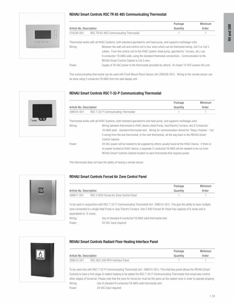
REHAU Smart Controls RSC TR 65 485 Communicating Thermostat
Package Minimum
Article No. Description Quantity Order
214228-001 RSC TR 65 485 Communicating Thermostat 1 1
Thermostat works with all HVAC Systems, both standard gas/electric and heat pump, and supports multistage units.
Wiring: Between the wall unit and control unit is four wires which can be themostat wiring, Cat 3 or Cat 5
cables. From the control unit to the HVAC system (heat pump, gas/electric furnace, etc.) use
8 conductor/ 18 AWG soild, using the standard themostat connections. Communication to the
REHAU Smart Control Cabinet is Cat 5 wire.
Power: Supply of 24 VAC power to the thermostat (provided by others) On-board 12 VDC powers the unit.
This communicating thermostat can be used with Flush Mount Room Sensor (Art.298356-001). Wiring to the remote sensor can
be done using 2 conductor/18 AWG from the wall display unit.
REHAU Smart Controls RSC T-32-P Communicating Thermostat
Package Minimum
Article No. Description Quantity Order
398010-001 RSC T-32-P Communicating Thermostat 1 1
Thermostat works with all HVAC Systems, both standard gas/electric and heat pump, and supports multistage units.
Wiring: Wiring between thermostat to HVAC device (Heat Pump, Gas/Electric Furnace, etc) 8 Conductor/
18 AWG solid - standard thermostat wire. Wiring for communication should be “Daisy-Chained – Cat
5 wiring from the last thermostat, to the next thermostat, all the way back to the REHAU Smart
Control Cabinet.
Power: 24 VAC power will be needed to be supplied by others usually found at the HVAC Device. If there is
no power located at HVAC device, a separate 2 conductor/18 AWG will be needed to be run from
REHAU Smart Controls Cabinet location to each thermostat that requires power.
This thermostat does not have the ability of having a remote sensor.
REHAU Smart Controls Forced Air Zone Control Panel
Package Minimum
Article No. Description Quantity Order
398011-001 RSC Z-600 Forced Air Zone Control Panel 1 1
To be used in conjunction with RSC T-32-P Communicating Thermostat (Art. 398010-001). This give the ability to have multiple
zone connected to a single Heat Pump or Gas/ Electric Furnace. One Z-600 Forced Air Panel has capacity of 6 zones and is
expandable to 12 zones.
Wiring: Use of standard 8 conductor/18 AWG solid thermostat wire
Power: 24 VAC input required
REHAU Smart Controls Radiant Floor Heating Interface Panel
Package Minimum
Article No. Description Quantity Order
398012-001 RSC GEO-200 RFH Interface Panel 1 1
To be used only with RSC T-32-P Communicating Thermostat (Art. 398010-001). This interface panel allows the REHAU Smart
Controls to have a first stage of radiant heating to be added the RSC T-32-P Communicating Thermostat that would also control
other stages of forced air. Please note that the zone for forced air must be the same as the radiant zone in order to operate properly.
Wiring: Use of standard 8 conductor/18 AWG solid thermostat wire
Power: 24 VAC input required
1.20
RH a
nd S
IM
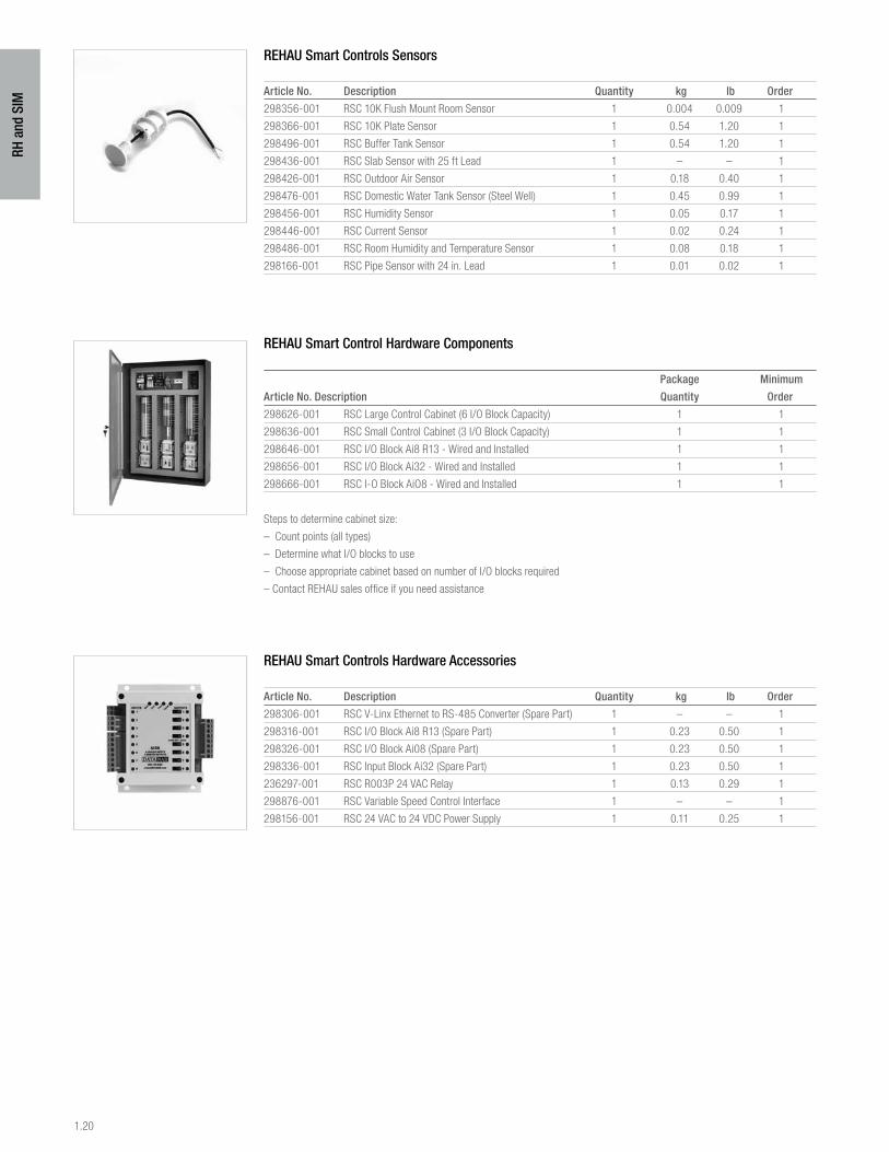
REHAU Smart Controls Sensors
Article No. Description Quantity kg lb Order
298356-001 RSC 10K Flush Mount Room Sensor 1 0.004 0.009 1
298366-001 RSC 10K Plate Sensor 1 0.54 1.20 1
298496-001 RSC Buffer Tank Sensor 1 0.54 1.20 1
298436-001 RSC Slab Sensor with 25 ft Lead 1 – – 1
298426-001 RSC Outdoor Air Sensor 1 0.18 0.40 1
298476-001 RSC Domestic Water Tank Sensor (Steel Well) 1 0.45 0.99 1
298456-001 RSC Humidity Sensor 1 0.05 0.17 1
298446-001 RSC Current Sensor 1 0.02 0.24 1
298486-001 RSC Room Humidity and Temperature Sensor 1 0.08 0.18 1
298166-001 RSC Pipe Sensor with 24 in. Lead 1 0.01 0.02 1
REHAU Smart Control Hardware Components
Package Minimum
Article No. Description Quantity Order
298626-001 RSC Large Control Cabinet (6 I/O Block Capacity) 1 1
298636-001 RSC Small Control Cabinet (3 I/O Block Capacity) 1 1
298646-001 RSC I/O Block Ai8 R13 - Wired and Installed 1 1
298656-001 RSC I/O Block Ai32 - Wired and Installed 1 1
298666-001 RSC I-O Block AiO8 - Wired and Installed 1 1
Steps to determine cabinet size:
– Count points (all types)
– Determine what I/O blocks to use
– Choose appropriate cabinet based on number of I/O blocks required
– Contact REHAU sales office if you need assistance
REHAU Smart Controls Hardware Accessories
Article No. Description Quantity kg lb Order
298306-001 RSC V-Linx Ethernet to RS-485 Converter (Spare Part) 1 – – 1
298316-001 RSC I/O Block Ai8 R13 (Spare Part) 1 0.23 0.50 1
298326-001 RSC I/O Block Ai08 (Spare Part) 1 0.23 0.50 1
298336-001 RSC Input Block Ai32 (Spare Part) 1 0.23 0.50 1
236297-001 RSC R003P 24 VAC Relay 1 0.13 0.29 1
298876-001 RSC Variable Speed Control Interface 1 – – 1
298156-001 RSC 24 VAC to 24 VDC Power Supply 1 0.11 0.25 1
1.21
RH a
nd S
IM
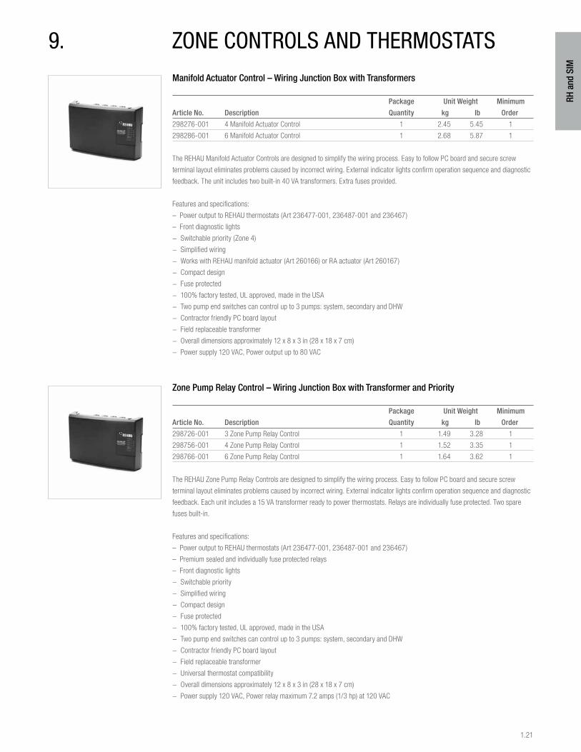
Manifold Actuator Control – Wiring Junction Box with Transformers
Package Unit Weight Minimum
Article No. Description Quantity kg lb Order
298276-001 4 Manifold Actuator Control 1 2.45 5.45 1
298286-001 6 Manifold Actuator Control 1 2.68 5.87 1
The REHAU Manifold Actuator Controls are designed to simplify the wiring process. Easy to follow PC board and secure screw
terminal layout eliminates problems caused by incorrect wiring. External indicator lights confirm operation sequence and diagnostic
feedback. The unit includes two built-in 40 VA transformers. Extra fuses provided.
Features and specifications:
– Power output to REHAU thermostats (Art 236477-001, 236487-001 and 236467)
– Front diagnostic lights
− Switchable priority (Zone 4)
− Simplified wiring
− Works with REHAU manifold actuator (Art 260166) or RA actuator (Art 260167)
− Compact design
− Fuse protected
− 100% factory tested, UL approved, made in the USA
− Two pump end switches can control up to 3 pumps: system, secondary and DHW
− Contractor friendly PC board layout
− Field replaceable transformer
− Overall dimensions approximately 12 x 8 x 3 in (28 x 18 x 7 cm)
− Power supply 120 VAC, Power output up to 80 VAC
Zone Pump Relay Control – Wiring Junction Box with Transformer and Priority
Package Unit Weight Minimum
Article No. Description Quantity kg lb Order
298726-001 3 Zone Pump Relay Control 1 1.49 3.28 1
298756-001 4 Zone Pump Relay Control 1 1.52 3.35 1
298766-001 6 Zone Pump Relay Control 1 1.64 3.62 1
The REHAU Zone Pump Relay Controls are designed to simplify the wiring process. Easy to follow PC board and secure screw
terminal layout eliminates problems caused by incorrect wiring. External indicator lights confirm operation sequence and diagnostic
feedback. Each unit includes a 15 VA transformer ready to power thermostats. Relays are individually fuse protected. Two spare
fuses built-in.
Features and specifications:
– Power output to REHAU thermostats (Art 236477-001, 236487-001 and 236467)
– Premium sealed and individually fuse protected relays
– Front diagnostic lights
− Switchable priority
− Simplified wiring
− Compact design
− Fuse protected
− 100% factory tested, UL approved, made in the USA
− Two pump end switches can control up to 3 pumps: system, secondary and DHW
− Contractor friendly PC board layout
− Field replaceable transformer
− Universal thermostat compatibility
− Overall dimensions approximately 12 x 8 x 3 in (28 x 18 x 7 cm)
− Power supply 120 VAC, Power relay maximum 7.2 amps (1/3 hp) at 120 VAC
9. zone controls and thermostats
1.22
RH a
nd S
IM
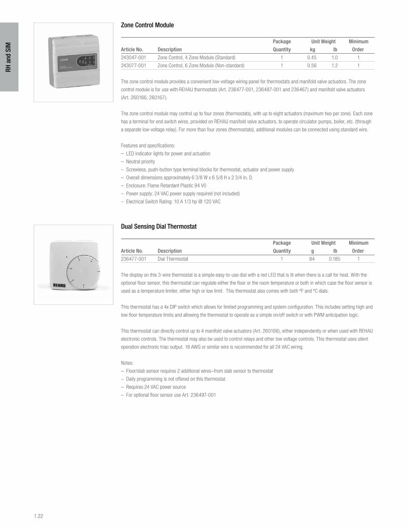
Zone Control Module
Package Unit Weight Minimum
Article No. Description Quantity kg lb Order
243047-001 Zone Control, 4 Zone Module (Standard) 1 0.45 1.0 1
243077-001 Zone Control, 6 Zone Module (Non-standard) 1 0.56 1.2 1
The zone control module provides a convenient low-voltage wiring panel for thermostats and manifold valve actuators. The zone
control module is for use with REHAU thermostats (Art. 236477-001, 236487-001 and 236467) and manifold valve actuators
(Art. 260166, 260167).
The zone control module may control up to four zones (thermostats), with up to eight actuators (maximum two per zone). Each zone
has a terminal for end switch wires, provided on REHAU manifold valve actuators, to operate circulator pumps, boiler, etc. (through
a separate low-voltage relay). For more than four zones (thermostats), additional modules can be connected using standard wire.
Features and specifications:
– LED indicator lights for power and actuation
– Neutral priority
– Screwless, push-button type terminal blocks for thermostat, actuator and power supply
– Overall dimensions approximately 6 3/8 W x 6 5/8 H x 2 3/4 in. D
– Enclosure: Flame Retardant Plastic 94 V0
– Power supply: 24 VAC power supply required (not included)
– Electrical Switch Rating: 10 A 1/3 hp @ 120 VAC
Dual Sensing Dial Thermostat
Package Unit Weight Minimum
Article No. Description Quantity g lb Order
236477-001 Dial Thermostat 1 84 0.185 1
The display on this 3-wire thermostat is a simple easy-to-use dial with a red LED that is lit when there is a call for heat. With the
optional floor sensor, this thermostat can regulate either the floor or the room temperature or both in which case the floor sensor is
used as a temperature limiter, either high or low limit. This thermostat also comes with both ºF and ºC dials.
This thermostat has a 4x DIP switch which allows for limited programming and system configuration. This includes setting high and
low floor temperature limits and allowing the thermostat to operate as a simple on/off switch or with PWM anticipation logic.
This thermostat can directly control up to 4 manifold valve actuators (Art. 260166), either independently or when used with REHAU
electronic controls. The thermostat may also be used to control relays and other low voltage controls. This thermostat uses silent
operation electronic triac output. 18 AWG or similar wire is recommended for all 24 VAC wiring.
Notes:
– Floor/slab sensor requires 2 additional wires–from slab sensor to thermostat
– Daily programming is not offered on this thermostat
– Requires 24 VAC power source
– For optional floor sensor use Art. 236497-001
1.23
RH a
nd S
IM
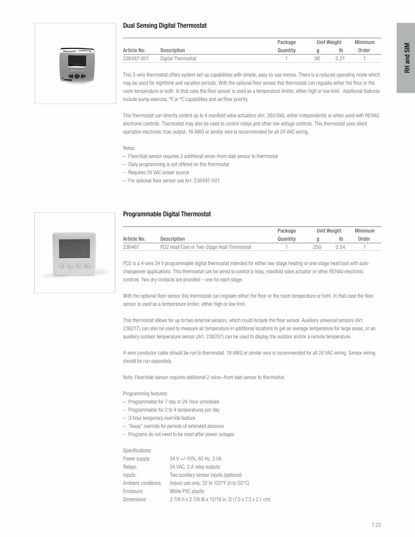
Dual Sensing Digital Thermostat
Package Unit Weight Minimum
Article No. Description Quantity g lb Order
236487-001 Digital Thermostat 1 96 0.21 1
This 3-wire thermostat offers system set-up capabilities with simple, easy-to-use menus. There is a reduced operating mode which
may be used for nighttime and vacation periods. With the optional floor sensor this thermostat can regulate either the floor or the
room temperature or both. In that case the floor sensor is used as a temperature limiter, either high or low limit. Additional features
include pump exercise, ºF or ºC capabilities and air/floor priority.
This thermostat can directly control up to 4 manifold valve actuators (Art. 260166), either independently or when used with REHAU
electronic controls. Thermostat may also be used to control relays and other low voltage controls. This thermostat uses silent
operation electronic triac output. 18 AWG or similar wire is recommended for all 24 VAC wiring.
Notes:
– Floor/slab sensor requires 2 additional wires–from slab sensor to thermostat
– Daily programming is not offered on this thermostat
– Requires 24 VAC power source
– For optional floor sensor use Art. 236497-001
Programmable Digital Thermostat
Package Unit Weight Minimum
Article No. Description Quantity g lb Order
236467 PD2 Heat/Cool or Two-Stage Heat Thermostat 1 250 0.54 1
PD2 is a 4-wire 24 V programmable digital thermostat intended for either two-stage heating or one-stage heat/cool with auto-
changeover applications. This thermostat can be wired to control a relay, manifold valve actuator or other REHAU electronic
controls. Two dry contacts are provided – one for each stage.
With the optional floor sensor this thermostat can regulate either the floor or the room temperature or both. In that case the floor
sensor is used as a temperature limiter, either high or low limit.
This thermostat allows for up to two external sensors, which could include the floor sensor. Auxiliary universal sensors (Art.
236217) can also be used to measure air temperature in additional locations to get an average temperature for large areas, or an
auxiliary outdoor temperature sensor (Art. 236207) can be used to display the outdoor and/or a remote temperature.
4-wire conductor cable should be run to thermostat. 18 AWG or similar wire is recommended for all 24 VAC wiring. Sensor wiring
should be run separately.
Note: Floor/slab sensor requires additional 2 wires–from slab sensor to thermostat.
Programming features:
– Programmable for 7-day or 24-hour schedules
– Programmable for 2 to 4 temperatures per day
– 3-hour temporary override feature
– "Away" override for periods of extended absence
– Programs do not need to be reset after power outages
Specifications:
Power supply: 24 V +/-10%, 60 Hz, 3 VA
Relays: 24 VAC, 2 A relay outputs
Inputs: Two auxiliary sensor inputs (optional)
Ambient conditions: Indoor use only, 32 to 122°F (0 to 50°C)
Enclosure: White PVC plastic
Dimensions: 2 7/8 H x 2 7/8 W x 13/16 in. D (7.3 x 7.3 x 2.1 cm)
1.24
RH a
nd S
IM
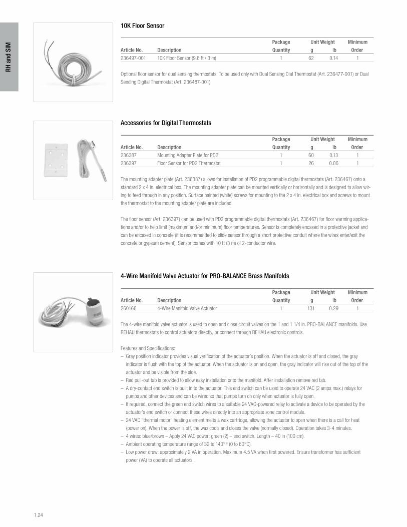
10K Floor Sensor
Package Unit Weight Minimum
Article No. Description Quantity g lb Order
236497-001 10K Floor Sensor (9.8 ft / 3 m) 1 62 0.14 1
Optional floor sensor for dual sensing thermostats. To be used only with Dual Sensing Dial Thermostat (Art. 236477-001) or Dual
Sending Digital Thermostat (Art. 236487-001).
Accessories for Digital Thermostats
Package Unit Weight Minimum
Article No. Description Quantity g lb Order
236387 Mounting Adapter Plate for PD2 1 60 0.13 1
236397 Floor Sensor for PD2 Thermostat 1 26 0.06 1
The mounting adapter plate (Art. 236387) allows for installation of PD2 programmable digital thermostats (Art. 236467) onto a
standard 2 x 4 in. electrical box. The mounting adapter plate can be mounted vertically or horizontally and is designed to allow wir-
ing to feed through in any position. Surface painted (white) screws for mounting to the 2 x 4 in. electrical box and screws to mount
the thermostat to the mounting adapter plate are included.
The floor sensor (Art. 236397) can be used with PD2 programmable digital thermostats (Art. 236467) for floor warming applica-
tions and/or to help limit (maximum and/or minimum) floor temperatures. Sensor is completely encased in a protective jacket and
can be encased in concrete (it is recommended to slide sensor through a short protective conduit where the wires enter/exit the
concrete or gypsum cement). Sensor comes with 10 ft (3 m) of 2-conductor wire.
4-Wire Manifold Valve Actuator for PRO-BALANCE Brass Manifolds
Package Unit Weight Minimum
Article No. Description Quantity g lb Order
260166 4-Wire Manifold Valve Actuator 1 131 0.29 1
The 4-wire manifold valve actuator is used to open and close circuit valves on the 1 and 1 1/4 in. PRO-BALANCE manifolds. Use
REHAU thermostats to control actuators directly, or connect through REHAU electronic controls.
Features and Specifications:
– Gray position indicator provides visual verification of the actuator’s position. When the actuator is off and closed, the gray
indicator is flush with the top of the actuator. When the actuator is on and open, the gray indicator will rise out of the top of the
actuator and be visible from the side.
– Red pull-out tab is provided to allow easy installation onto the manifold. After installation remove red tab.
– A dry-contact end switch is built in to the actuator. This end switch can be used to operate 24 VAC (2 amps max.) relays for
pumps and other devices and can be wired so that pumps turn on only when actuator is fully open.
– If required, connect the green end switch wires to a suitable 24 VAC-powered relay to activate a device to be operated by the
actuator’s end switch or connect these wires directly into an appropriate zone control module.
– 24 VAC "thermal motor" heating element melts a wax cartridge, allowing the actuator to open when there is a call for heat
(power on). When the power is off, the wax cools and closes the valve (normally closed). Operation takes 3-4 minutes.
– 4 wires: blue/brown – Apply 24 VAC power; green (2) – end switch. Length – 40 in (100 cm).
– Ambient operating temperature range of 32 to 140°F (0 to 60°C).
– Low power draw: approximately 2 VA in operation. Maximum 4.5 VA when first powered. Ensure transformer has sufficient
power (VA) to operate all actuators.
1.25
RH a
nd S
IM
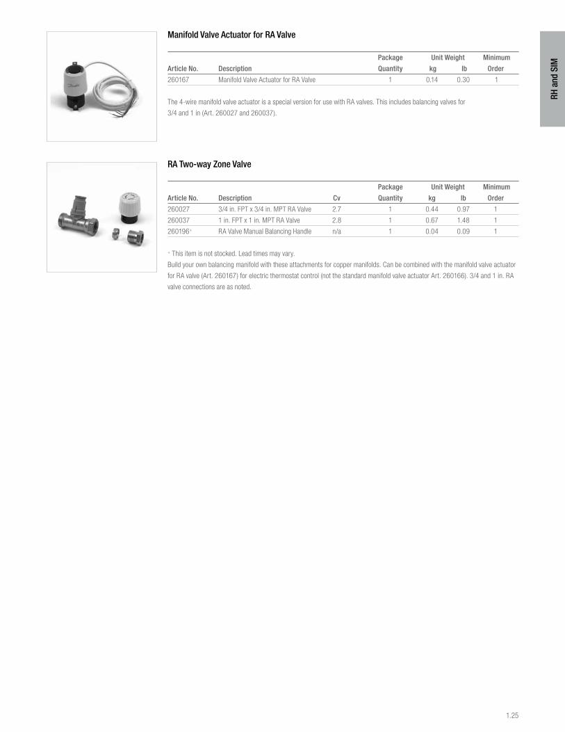
Manifold Valve Actuator for RA Valve
Package Unit Weight Minimum
Article No. Description Quantity kg lb Order
260167 Manifold Valve Actuator for RA Valve 1 0.14 0.30 1
The 4-wire manifold valve actuator is a special version for use with RA valves. This includes balancing valves for
3/4 and 1 in (Art. 260027 and 260037).
RA Two-way Zone Valve
Package Unit Weight Minimum
Article No. Description Cv Quantity kg lb Order
260027 3/4 in. FPT x 3/4 in. MPT RA Valve 2.7 1 0.44 0.97 1
260037 1 in. FPT x 1 in. MPT RA Valve 2.8 1 0.67 1.48 1
260196+ RA Valve Manual Balancing Handle n/a 1 0.04 0.09 1
+ This item is not stocked. Lead times may vary.
Build your own balancing manifold with these attachments for copper manifolds. Can be combined with the manifold valve actuator
for RA valve (Art. 260167) for electric thermostat control (not the standard manifold valve actuator Art. 260166). 3/4 and 1 in. RA
valve connections are as noted.

1.26
RH a
nd S
IM
10. everloc fittingsEVERLOC fittings and sleeves create reliable connections that can be walled-in or embedded directly in a thermal mass when
wrapped in waterproof, adhesive-free tape or RAUCROSS™ (Art. 253615, 253625) heat shrink tubing to help reduce corrosion
caused by the surrounding environment. Check local codes for compliance. Installation is easy with EVERLOC tools.
EVERLOC fittings are produced from solid brass stock. Elbows and tees are hot-forged for superior strength and durability, while
straight fittings are machined from solid brass rod. EVERLOC fittings and sleeves meet the performance requirements of ASTM
F877 and ASTM F2080.
EVERLOC fittings are not certified for potable water applications.
EVERLOC Sleeves
Package Quantity Unit Weight Minimum
Article No. Description Box Carton g lb Order
243507-101 3/8 in. EVERLOC Sleeve 150 900 20 0.05 1 box
260077-101 1/2 in. EVERLOC Sleeve 150 900 23 0.05 1 box
243607-101 5/8 in. EVERLOC Sleeve 40 240 56 0.12 1 box
260577-101 3/4 in. EVERLOC Sleeve 80 480 37 0.08 1 box
260877-101 1 in. EVERLOC Sleeve 40 240 73 0.16 1 box
235507-101 1 1/4 in. EVERLOC Sleeve 25 150 105 0.23 1 box
235707-101 1 1/2 in. EVERLOC Sleeve 20 120 132 0.29 1 box
235907-101 2 in. EVERLOC Sleeve 10 60 245 0.54 1 box
Sleeves are unplated brass. Tapered end installs toward fitting.
EVERLOC Couplings
Package Quantity Unit Weight Minimum
Article No. Description Box Carton g lb Order
243517-101 3/8 x 3/8 in. EVERLOC Coupling 70 420 36 0.08 1 box
260227-101 1/2 x 1/2 in. EVERLOC Coupling 60 360 54 0.12 1 box
243627-101 5/8 x 5/8 in. EVERLOC Coupling 40 240 76 0.17 1 box
260317-101 3/4 x 3/4 in. EVERLOC Coupling 35 210 82 0.18 1 box
260427-101 1 x 1 in. EVERLOC Coupling 20 120 136 0.30 1 box
235527-101 1 1/4 x 1 1/4 in. EVERLOC Coupling 5 30 227 0.50 1 box
235727-101 1 1/2 x 1 1/2 in. EVERLOC Coupling 5 30 345 0.76 1 box
235927-101 2 x 2 in. EVERLOC Coupling 3 18 599 1.32 1 box
Order EVERLOC sleeves separately.
EVERLOC Reducer Couplings
Package Quantity Unit Weight Minimum
Article No. Description Box Carton g lb Order
260247-101 3/4 x 1/2 in. EVERLOC Coupling 45 270 68 0.15 1 box
260447-101 1 x 3/4 in. EVERLOC Coupling 25 150 114 0.25 1 box
235517-101 1 1/4 x 1 in. EVERLOC Coupling 10 60 195 0.43 1 box
235717-101 1 1/2 x 1 1/4 in. EVERLOC Coupling 5 30 272 0.60 1 box
235737-101 1 1/2 x 1 in. EVERLOC Coupling 5 30 277 0.61 1 box
235917-101 2 x 1 1/2 in. EVERLOC Coupling 3 18 503 1.11 1 box
235937-101 2 x 1 1/4 in. EVERLOC Coupling 3 18 595 1.31 1 box
235947-101 2 x 1 in. EVERLOC Coupling 3 18 440 0.97 1 box
Order EVERLOC sleeves separately.
1.27
RH a
nd S
IM
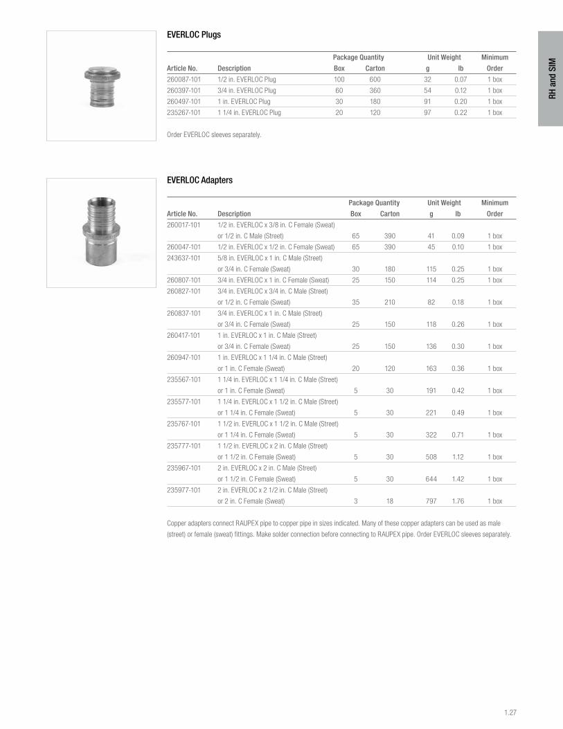
EVERLOC Plugs
Package Quantity Unit Weight Minimum
Article No. Description Box Carton g lb Order
260087-101 1/2 in. EVERLOC Plug 100 600 32 0.07 1 box
260397-101 3/4 in. EVERLOC Plug 60 360 54 0.12 1 box
260497-101 1 in. EVERLOC Plug 30 180 91 0.20 1 box
235267-101 1 1/4 in. EVERLOC Plug 20 120 97 0.22 1 box
Order EVERLOC sleeves separately.
EVERLOC Adapters
Package Quantity Unit Weight Minimum
Article No. Description Box Carton g lb Order
260017-101 1/2 in. EVERLOC x 3/8 in. C Female (Sweat)
or 1/2 in. C Male (Street) 65 390 41 0.09 1 box
260047-101 1/2 in. EVERLOC x 1/2 in. C Female (Sweat) 65 390 45 0.10 1 box
243637-101 5/8 in. EVERLOC x 1 in. C Male (Street)
or 3/4 in. C Female (Sweat) 30 180 115 0.25 1 box
260807-101 3/4 in. EVERLOC x 1 in. C Female (Sweat) 25 150 114 0.25 1 box
260827-101 3/4 in. EVERLOC x 3/4 in. C Male (Street)
or 1/2 in. C Female (Sweat) 35 210 82 0.18 1 box
260837-101 3/4 in. EVERLOC x 1 in. C Male (Street)
or 3/4 in. C Female (Sweat) 25 150 118 0.26 1 box
260417-101 1 in. EVERLOC x 1 in. C Male (Street)
or 3/4 in. C Female (Sweat) 25 150 136 0.30 1 box
260947-101 1 in. EVERLOC x 1 1/4 in. C Male (Street)
or 1 in. C Female (Sweat) 20 120 163 0.36 1 box
235567-101 1 1/4 in. EVERLOC x 1 1/4 in. C Male (Street)
or 1 in. C Female (Sweat) 5 30 191 0.42 1 box
235577-101 1 1/4 in. EVERLOC x 1 1/2 in. C Male (Street)
or 1 1/4 in. C Female (Sweat) 5 30 221 0.49 1 box
235767-101 1 1/2 in. EVERLOC x 1 1/2 in. C Male (Street)
or 1 1/4 in. C Female (Sweat) 5 30 322 0.71 1 box
235777-101 1 1/2 in. EVERLOC x 2 in. C Male (Street)
or 1 1/2 in. C Female (Sweat) 5 30 508 1.12 1 box
235967-101 2 in. EVERLOC x 2 in. C Male (Street)
or 1 1/2 in. C Female (Sweat) 5 30 644 1.42 1 box
235977-101 2 in. EVERLOC x 2 1/2 in. C Male (Street)
or 2 in. C Female (Sweat) 3 18 797 1.76 1 box
Copper adapters connect RAUPEX pipe to copper pipe in sizes indicated. Many of these copper adapters can be used as male
(street) or female (sweat) fittings. Make solder connection before connecting to RAUPEX pipe. Order EVERLOC sleeves separately.
1.28
RH a
nd S
IM
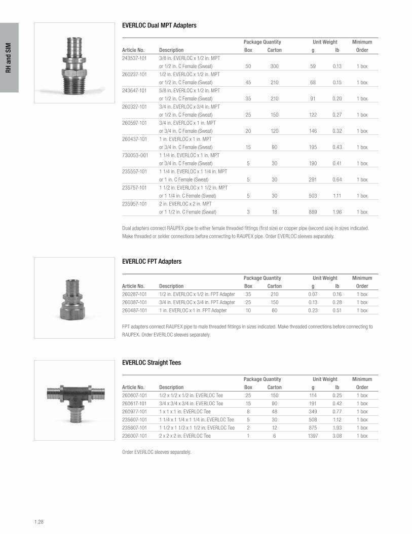
EVERLOC Dual MPT Adapters
Package Quantity Unit Weight Minimum
Article No. Description Box Carton g lb Order
243537-101 3/8 in. EVERLOC x 1/2 in. MPT
or 1/2 in. C Female (Sweat) 50 300 59 0.13 1 box
260237-101 1/2 in. EVERLOC x 1/2 in. MPT
or 1/2 in. C Female (Sweat) 45 210 68 0.15 1 box
243647-101 5/8 in. EVERLOC x 1/2 in. MPT
or 1/2 in. C Female (Sweat) 35 210 91 0.20 1 box
260327-101 3/4 in. EVERLOC x 3/4 in. MPT
or 1/2 in. C Female (Sweat) 25 150 122 0.27 1 box
260597-101 3/4 in. EVERLOC x 1 in. MPT
or 3/4 in. C Female (Sweat) 20 120 146 0.32 1 box
260437-101 1 in. EVERLOC x 1 in. MPT
or 3/4 in. C Female (Sweat) 15 90 195 0.43 1 box
730053-001 1 1/4 in. EVERLOC x 1 in. MPT
or 3/4 in. C Female (Sweat) 5 30 190 0.41 1 box
235557-101 1 1/4 in. EVERLOC x 1 1/4 in. MPT
or 1 in. C Female (Sweat) 5 30 291 0.64 1 box
235757-101 1 1/2 in. EVERLOC x 1 1/2 in. MPT
or 1 1/4 in. C Female (Sweat) 5 30 503 1.11 1 box
235957-101 2 in. EVERLOC x 2 in. MPT
or 1 1/2 in. C Female (Sweat) 3 18 889 1.96 1 box
Dual adapters connect RAUPEX pipe to either female threaded fittings (first size) or copper pipe (second size) in sizes indicated.
Make threaded or solder connections before connecting to RAUPEX pipe. Order EVERLOC sleeves separately.
EVERLOC FPT Adapters
Package Quantity Unit Weight Minimum
Article No. Description Box Carton g lb Order
260287-101 1/2 in. EVERLOC x 1/2 in. FPT Adapter 35 210 0.07 0.16 1 box
260387-101 3/4 in. EVERLOC x 3/4 in. FPT Adapter 25 150 0.13 0.28 1 box
260487-101 1 in. EVERLOC x 1 in. FPT Adapter 10 60 0.23 0.51 1 box
FPT adapters connect RAUPEX pipe to male threaded fittings in sizes indicated. Make threaded connections before connecting to
RAUPEX. Order EVERLOC sleeves separately.
EVERLOC Straight Tees
Package Quantity Unit Weight Minimum
Article No. Description Box Carton g lb Order
260607-101 1/2 x 1/2 x 1/2 in. EVERLOC Tee 25 150 114 0.25 1 box
260617-101 3/4 x 3/4 x 3/4 in. EVERLOC Tee 15 90 191 0.42 1 box
260977-101 1 x 1 x 1 in. EVERLOC Tee 8 48 349 0.77 1 box
235607-101 1 1/4 x 1 1/4 x 1 1/4 in. EVERLOC Tee 5 30 508 1.12 1 box
235807-101 1 1/2 x 1 1/2 x 1 1/2 in. EVERLOC Tee 2 12 875 1.93 1 box
236007-101 2 x 2 x 2 in. EVERLOC Tee 1 6 1397 3.08 1 box
Order EVERLOC sleeves separately.
1.29
RH a
nd S
IM
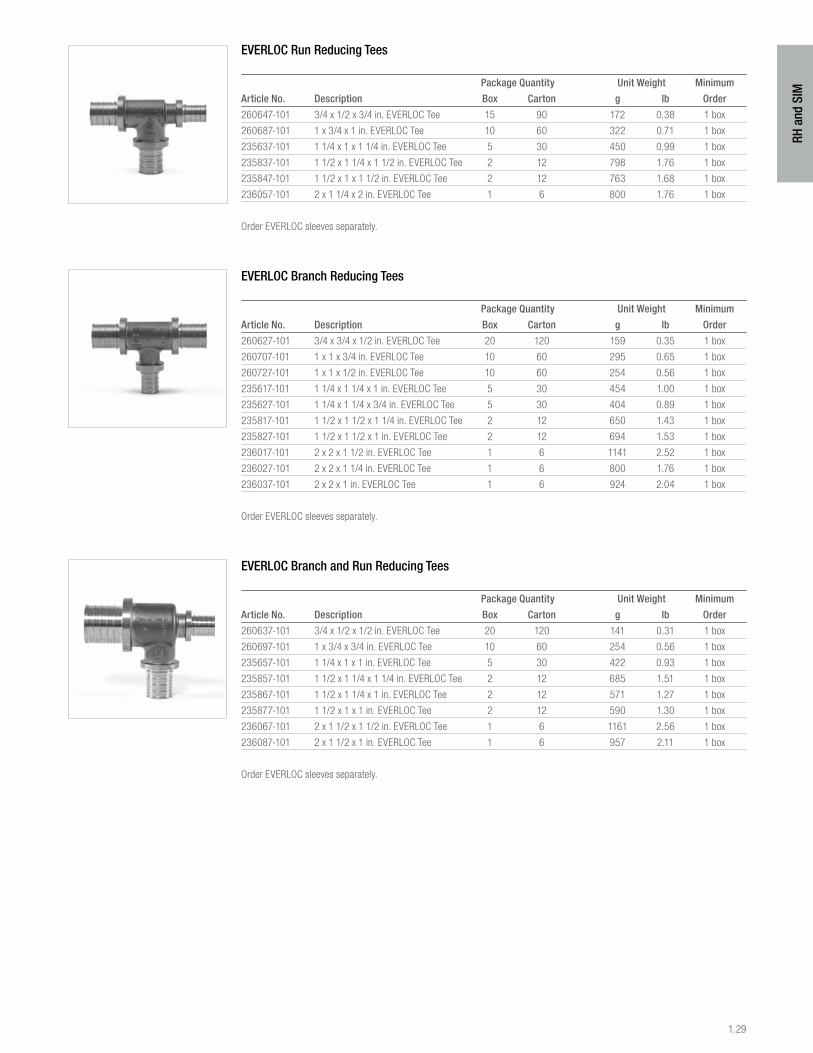
EVERLOC Run Reducing Tees
Package Quantity Unit Weight Minimum
Article No. Description Box Carton g lb Order
260647-101 3/4 x 1/2 x 3/4 in. EVERLOC Tee 15 90 172 0.38 1 box
260687-101 1 x 3/4 x 1 in. EVERLOC Tee 10 60 322 0.71 1 box
235637-101 1 1/4 x 1 x 1 1/4 in. EVERLOC Tee 5 30 450 0.99 1 box
235837-101 1 1/2 x 1 1/4 x 1 1/2 in. EVERLOC Tee 2 12 798 1.76 1 box
235847-101 1 1/2 x 1 x 1 1/2 in. EVERLOC Tee 2 12 763 1.68 1 box
236057-101 2 x 1 1/4 x 2 in. EVERLOC Tee 1 6 800 1.76 1 box
Order EVERLOC sleeves separately.
EVERLOC Branch Reducing Tees
Package Quantity Unit Weight Minimum
Article No. Description Box Carton g lb Order
260627-101 3/4 x 3/4 x 1/2 in. EVERLOC Tee 20 120 159 0.35 1 box
260707-101 1 x 1 x 3/4 in. EVERLOC Tee 10 60 295 0.65 1 box
260727-101 1 x 1 x 1/2 in. EVERLOC Tee 10 60 254 0.56 1 box
235617-101 1 1/4 x 1 1/4 x 1 in. EVERLOC Tee 5 30 454 1.00 1 box
235627-101 1 1/4 x 1 1/4 x 3/4 in. EVERLOC Tee 5 30 404 0.89 1 box
235817-101 1 1/2 x 1 1/2 x 1 1/4 in. EVERLOC Tee 2 12 650 1.43 1 box
235827-101 1 1/2 x 1 1/2 x 1 in. EVERLOC Tee 2 12 694 1.53 1 box
236017-101 2 x 2 x 1 1/2 in. EVERLOC Tee 1 6 1141 2.52 1 box
236027-101 2 x 2 x 1 1/4 in. EVERLOC Tee 1 6 800 1.76 1 box
236037-101 2 x 2 x 1 in. EVERLOC Tee 1 6 924 2.04 1 box
Order EVERLOC sleeves separately.
EVERLOC Branch and Run Reducing Tees
Package Quantity Unit Weight Minimum
Article No. Description Box Carton g lb Order
260637-101 3/4 x 1/2 x 1/2 in. EVERLOC Tee 20 120 141 0.31 1 box
260697-101 1 x 3/4 x 3/4 in. EVERLOC Tee 10 60 254 0.56 1 box
235657-101 1 1/4 x 1 x 1 in. EVERLOC Tee 5 30 422 0.93 1 box
235857-101 1 1/2 x 1 1/4 x 1 1/4 in. EVERLOC Tee 2 12 685 1.51 1 box
235867-101 1 1/2 x 1 1/4 x 1 in. EVERLOC Tee 2 12 571 1.27 1 box
235877-101 1 1/2 x 1 x 1 in. EVERLOC Tee 2 12 590 1.30 1 box
236067-101 2 x 1 1/2 x 1 1/2 in. EVERLOC Tee 1 6 1161 2.56 1 box
236087-101 2 x 1 1/2 x 1 in. EVERLOC Tee 1 6 957 2.11 1 box
Order EVERLOC sleeves separately.
1.30
RH a
nd S
IM
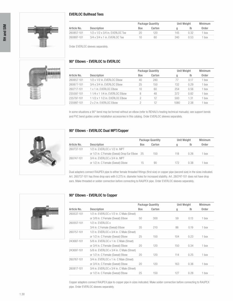
EVERLOC Bullhead Tees
Package Quantity Unit Weight Minimum
Article No. Description Box Carton g lb Order
260857-101 1/2 x 1/2 x 3/4 in. EVERLOC Tee 20 120 145 0.32 1 box
260897-101 3/4 x 3/4 x 1 in. EVERLOC Tee 10 60 240 0.53 1 box
Order EVERLOC sleeves separately.
90° Elbows - EVERLOC to EVERLOC
Package Quantity Unit Weight Minimum
Article No. Description Box Carton g lb Order
260657-101 1/2 x 1/2 in. EVERLOC Elbow 40 240 77 0.17 1 box
260677-101 3/4 x 3/4 in. EVERLOC Elbow 25 150 132 0.29 1 box
260717-101 1 x 1 in. EVERLOC Elbow 10 60 254 0.56 1 box
235597-101 1 1/4 x 1 1/4 in. EVERLOC Elbow 8 48 372 0.82 1 box
235797-101 1 1/2 x 1 1/2 in. EVERLOC Elbow 2 12 593 1.31 1 box
235997-101 2 x 2 in. EVERLOC Elbow 2 12 1080 2.38 1 box
In some situations a 90° bend may be formed without an elbow (refer to REHAU’s heating technical manuals); see support bends
and PVC bend guides under installation accessories in this catalog. Order EVERLOC sleeves separately.
90° Elbows - EVERLOC Dual MPT/Copper
Package Quantity Unit Weight Minimum
Article No. Description Box Carton g lb Order
260737-101 1/2 in. EVERLOC x 1/2 in. MPT
or 1/2 in. C Female (Sweat) Drop Ear Elbow 25 150 118 0.26 1 box
260747-101 3/4 in. EVERLOC x 3/4 in. MPT
or 1/2 in. C Female (Sweat) Elbow 15 90 172 0.38 1 box
Dual adapters connect RAUPEX pipe to either female threaded fittings (first size) or copper pipe (second size) in the sizes indicated.
Art. 260737-101 has three drop ears with 0.275 in. diameter holes for increased stability. Art. 260747-101 does not have drop
ears. Make threaded or solder connection before connecting to RAUPEX pipe. Order EVERLOC sleeves separately.
90° Elbows - EVERLOC to Copper
Package Quantity Unit Weight Minimum
Article No. Description Box Carton g lb Order
260537-101 1/2 in. EVERLOC x 1/2 in. C Male (Street)
or 3/8 in. C Female (Sweat) Elbow 50 300 59 0.13 1 box
260557-101 1/2 in. EVERLOC x
3/4 in. C Female (Sweat) Elbow 35 210 86 0.19 1 box
260757-101 1/2 in. EVERLOC x 3/4 in. C Male (Street)
or 1/2 in. C Female (Sweat) Elbow 25 150 104 0.23 1 box
243687-101 5/8 in. EVERLOC x 1 in. C Male (Street)
or 3/4 in. C Female (Sweat) Elbow 20 120 150 0.34 1 box
243697-101 5/8 in. EVERLOC x 3/4 in. C Male (Street)
or 1/2 in. C Female (Sweat) Elbow 20 120 114 0.25 1 box
260767-101 3/4 in. EVERLOC x 1 in. C Male (Street)
or 3/4 in. C Female (Sweat) Elbow 20 120 163 0.36 1 box
260817-101 3/4 in. EVERLOC x 3/4 in. C Male (Street)
or 1/2 in. C Female (Sweat) Elbow 25 150 127 0.28 1 box
Copper adapters connect RAUPEX pipe to copper pipe in sizes indicated. Make solder connection before connecting to RAUPEX
pipe. Order EVERLOC sleeves separately.
1.31
RH a
nd S
IM
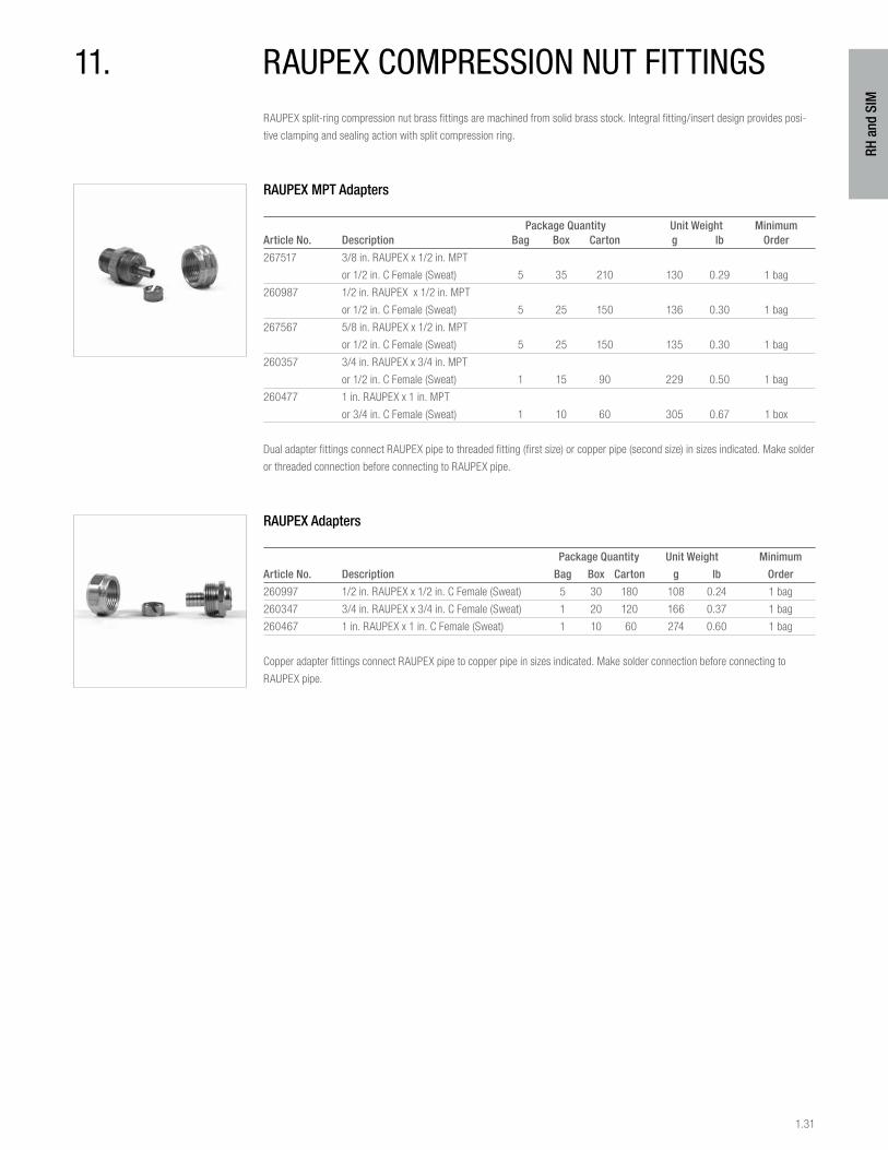
11. raupeX compression nut fittingsRAUPEX split-ring compression nut brass fittings are machined from solid brass stock. Integral fitting/insert design provides posi-
tive clamping and sealing action with split compression ring.
RAUPEX MPT Adapters
Package Quantity Unit Weight MinimumArticle No. Description Bag Box Carton g lb Order
267517 3/8 in. RAUPEX x 1/2 in. MPT
or 1/2 in. C Female (Sweat) 5 35 210 130 0.29 1 bag
260987 1/2 in. RAUPEX x 1/2 in. MPT
or 1/2 in. C Female (Sweat) 5 25 150 136 0.30 1 bag
267567 5/8 in. RAUPEX x 1/2 in. MPT
or 1/2 in. C Female (Sweat) 5 25 150 135 0.30 1 bag
260357 3/4 in. RAUPEX x 3/4 in. MPT
or 1/2 in. C Female (Sweat) 1 15 90 229 0.50 1 bag
260477 1 in. RAUPEX x 1 in. MPT
or 3/4 in. C Female (Sweat) 1 10 60 305 0.67 1 box
Dual adapter fittings connect RAUPEX pipe to threaded fitting (first size) or copper pipe (second size) in sizes indicated. Make solder
or threaded connection before connecting to RAUPEX pipe.
RAUPEX Adapters
Package Quantity Unit Weight Minimum
Article No. Description Bag Box Carton g lb Order
260997 1/2 in. RAUPEX x 1/2 in. C Female (Sweat) 5 30 180 108 0.24 1 bag
260347 3/4 in. RAUPEX x 3/4 in. C Female (Sweat) 1 20 120 166 0.37 1 bag
260467 1 in. RAUPEX x 1 in. C Female (Sweat) 1 10 60 274 0.60 1 bag
Copper adapter fittings connect RAUPEX pipe to copper pipe in sizes indicated. Make solder connection before connecting to
RAUPEX pipe.
1.32
RH a
nd S
IM
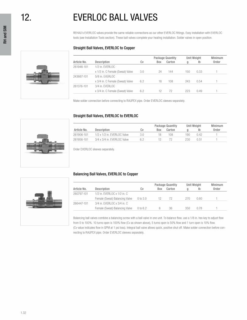
12. everloc ball valvesREHAU’s EVERLOC valves provide the same reliable connections as our other EVERLOC fittings. Easy installation with EVERLOC
tools (see Installation Tools section). These ball valves complete your heating installation. Solder valves in open position.
Straight Ball Valves, EVERLOC to Copper
Package Quantity Unit Weight MinimumArticle No. Description Cv Box Carton g lb Order
261946-101 1/2 in. EVERLOC
x 1/2 in. C Female (Sweat) Valve 3.0 24 144 150 0.33 1
243667-101 5/8 in. EVERLOC
x 3/4 in. C Female (Sweat) Valve 6.2 18 108 243 0.54 1
261376-101 3/4 in. EVERLOC
x 3/4 in. C Female (Sweat) Valve 6.2 12 72 223 0.49 1
Make solder connection before connecting to RAUPEX pipe. Order EVERLOC sleeves separately.
Straight Ball Valves, EVERLOC to EVERLOC
Package Quantity Unit Weight Minimum Article No. Description Cv Box Carton g lb Order
261906-101 1/2 x 1/2 in. EVERLOC Valve 3.0 18 108 190 0.42 1
261956-101 3/4 x 3/4 in. EVERLOC Valve 6.2 12 72 230 0.51 1
Order EVERLOC sleeves separately.
Balancing Ball Valves, EVERLOC to Copper
Package Quantity Unit Weight MinimumArticle No. Description Cv Box Carton g lb Order
260797-101 1/2 in. EVERLOC x 1/2 in. C
Female (Sweat) Balancing Valve 0 to 3.0 12 72 270 0.60 1
266447-101 3/4 in. EVERLOC x 3/4 in. C
Female (Sweat) Balancing Valve 0 to 6.2 6 36 350 0.78 1
Balancing ball valves combine a balancing screw with a ball valve in one unit. To balance flow, use a 1/8 in. hex key to adjust flow
from 0 to 100%. 10 turns open is 100% flow (Cv as shown above), 5 turns open is 50% flow and 1 turn open is 10% flow.
(Cv value indicates flow in GPM at 1 psi loss). Integral ball valve allows quick, positive shut off. Make solder connection before con-
necting to RAUPEX pipe. Order EVERLOC sleeves separately.
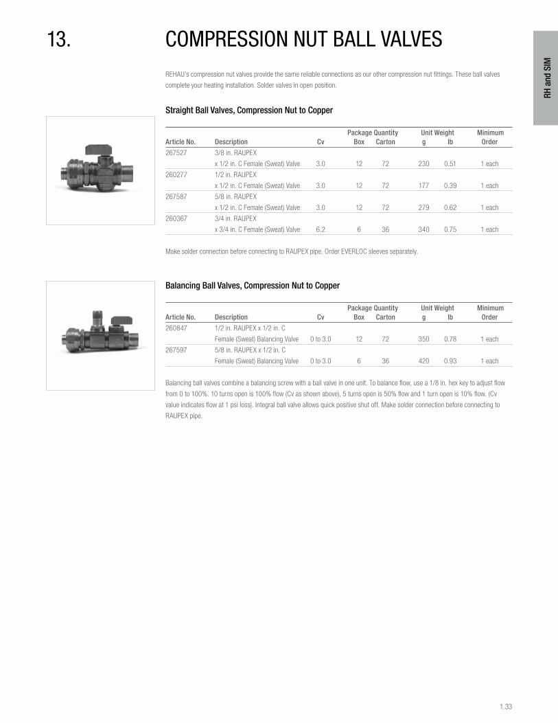
1.33
RH a
nd S
IM
13. compression nut ball valvesREHAU’s compression nut valves provide the same reliable connections as our other compression nut fittings. These ball valves
complete your heating installation. Solder valves in open position.
Straight Ball Valves, Compression Nut to Copper
Package Quantity Unit Weight MinimumArticle No. Description Cv Box Carton g lb Order
267527 3/8 in. RAUPEX
x 1/2 in. C Female (Sweat) Valve 3.0 12 72 230 0.51 1 each
260277 1/2 in. RAUPEX
x 1/2 in. C Female (Sweat) Valve 3.0 12 72 177 0.39 1 each
267587 5/8 in. RAUPEX
x 1/2 in. C Female (Sweat) Valve 3.0 12 72 279 0.62 1 each
260367 3/4 in. RAUPEX
x 3/4 in. C Female (Sweat) Valve 6.2 6 36 340 0.75 1 each
Make solder connection before connecting to RAUPEX pipe. Order EVERLOC sleeves separately.
Balancing Ball Valves, Compression Nut to Copper
Package Quantity Unit Weight MinimumArticle No. Description Cv Box Carton g lb Order
260847 1/2 in. RAUPEX x 1/2 in. C
Female (Sweat) Balancing Valve 0 to 3.0 12 72 350 0.78 1 each
267597 5/8 in. RAUPEX x 1/2 in. C
Female (Sweat) Balancing Valve 0 to 3.0 6 36 420 0.93 1 each
Balancing ball valves combine a balancing screw with a ball valve in one unit. To balance flow, use a 1/8 in. hex key to adjust flow
from 0 to 100%. 10 turns open is 100% flow (Cv as shown above), 5 turns open is 50% flow and 1 turn open is 10% flow. (Cv
value indicates flow at 1 psi loss). Integral ball valve allows quick positive shut off. Make solder connection before connecting to
RAUPEX pipe.
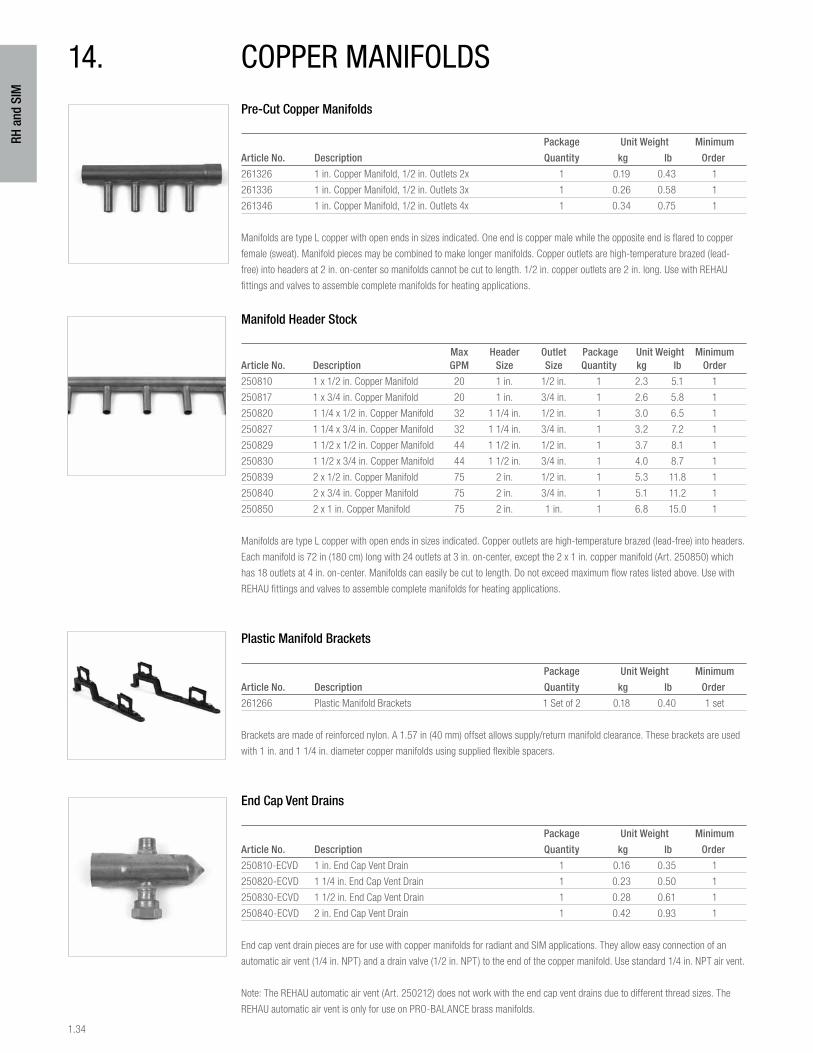
1.34
RH a
nd S
IM
Pre-Cut Copper Manifolds
Package Unit Weight Minimum
Article No. Description Quantity kg lb Order
261326 1 in. Copper Manifold, 1/2 in. Outlets 2x 1 0.19 0.43 1
261336 1 in. Copper Manifold, 1/2 in. Outlets 3x 1 0.26 0.58 1
261346 1 in. Copper Manifold, 1/2 in. Outlets 4x 1 0.34 0.75 1
Manifolds are type L copper with open ends in sizes indicated. One end is copper male while the opposite end is flared to copper
female (sweat). Manifold pieces may be combined to make longer manifolds. Copper outlets are high-temperature brazed (lead-
free) into headers at 2 in. on-center so manifolds cannot be cut to length. 1/2 in. copper outlets are 2 in. long. Use with REHAU
fittings and valves to assemble complete manifolds for heating applications.
Manifold Header Stock
Max Header Outlet Package Unit Weight MinimumArticle No. Description GPM Size Size Quantity kg lb Order
250810 1 x 1/2 in. Copper Manifold 20 1 in. 1/2 in. 1 2.3 5.1 1
250817 1 x 3/4 in. Copper Manifold 20 1 in. 3/4 in. 1 2.6 5.8 1
250820 1 1/4 x 1/2 in. Copper Manifold 32 1 1/4 in. 1/2 in. 1 3.0 6.5 1
250827 1 1/4 x 3/4 in. Copper Manifold 32 1 1/4 in. 3/4 in. 1 3.2 7.2 1
250829 1 1/2 x 1/2 in. Copper Manifold 44 1 1/2 in. 1/2 in. 1 3.7 8.1 1
250830 1 1/2 x 3/4 in. Copper Manifold 44 1 1/2 in. 3/4 in. 1 4.0 8.7 1
250839 2 x 1/2 in. Copper Manifold 75 2 in. 1/2 in. 1 5.3 11.8 1
250840 2 x 3/4 in. Copper Manifold 75 2 in. 3/4 in. 1 5.1 11.2 1
250850 2 x 1 in. Copper Manifold 75 2 in. 1 in. 1 6.8 15.0 1
Manifolds are type L copper with open ends in sizes indicated. Copper outlets are high-temperature brazed (lead-free) into headers.
Each manifold is 72 in (180 cm) long with 24 outlets at 3 in. on-center, except the 2 x 1 in. copper manifold (Art. 250850) which
has 18 outlets at 4 in. on-center. Manifolds can easily be cut to length. Do not exceed maximum flow rates listed above. Use with
REHAU fittings and valves to assemble complete manifolds for heating applications.
Plastic Manifold Brackets
Package Unit Weight Minimum
Article No. Description Quantity kg lb Order
261266 Plastic Manifold Brackets 1 Set of 2 0.18 0.40 1 set
Brackets are made of reinforced nylon. A 1.57 in (40 mm) offset allows supply/return manifold clearance. These brackets are used
with 1 in. and 1 1/4 in. diameter copper manifolds using supplied flexible spacers.
End Cap Vent Drains
Package Unit Weight Minimum
Article No. Description Quantity kg lb Order
250810-ECVD 1 in. End Cap Vent Drain 1 0.16 0.35 1
250820-ECVD 1 1/4 in. End Cap Vent Drain 1 0.23 0.50 1
250830-ECVD 1 1/2 in. End Cap Vent Drain 1 0.28 0.61 1
250840-ECVD 2 in. End Cap Vent Drain 1 0.42 0.93 1
End cap vent drain pieces are for use with copper manifolds for radiant and SIM applications. They allow easy connection of an
automatic air vent (1/4 in. NPT) and a drain valve (1/2 in. NPT) to the end of the copper manifold. Use standard 1/4 in. NPT air vent.
Note: The REHAU automatic air vent (Art. 250212) does not work with the end cap vent drains due to different thread sizes. The
REHAU automatic air vent is only for use on PRO-BALANCE brass manifolds.
14. copper manifolds
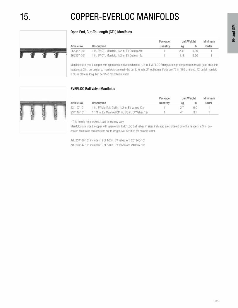
1.35
RH a
nd S
IM
15. copper-everloc manifoldsOpen End, Cut-To-Length (CTL) Manifolds
Package Unit Weight Minimum
Article No. Description Quantity kg lb Order
266357-001 1 in. EV CTL Manifold, 1/2 in. EV Outlets 24x 1 2.41 5.30 1
266397-001 1 in. EV CTL Manifold, 1/2 in. EV Outlets 12x 1 1.18 2.60 1
Manifolds are type L copper with open ends in sizes indicated. 1/2 in. EVERLOC fittings are high temperature brazed (lead-free) into
headers at 3 in. on-center so manifolds can easily be cut to length. 24-outlet manifolds are 72 in (180 cm) long. 12-outlet manifold
is 36 in (90 cm) long. Not certified for potable water.
EVERLOC Ball Valve Manifolds
Package Unit Weight Minimum
Article No. Description Quantity kg lb Order
234107-101 1 in. EV Manifold CM In, 1/2 in. EV Valves 12x 1 2.7 6.0 1
234147-101+ 1 1/4 in. EV Manifold CM In, 5/8 in. EV Valves 12x 1 4.1 9.1 1
+ This item is not stocked. Lead times may vary.
Manifolds are type L copper with open ends. EVERLOC ball valves in sizes indicated are soldered onto the headers at 3 in. on-
center. Manifolds can easily be cut to length. Not certified for potable water.
Art. 234107-101 includes 12 of 1/2 in. EV valves Art. 261946-101
Art. 234147-101 includes 12 of 5/8 in. EV valves Art. 243667-101
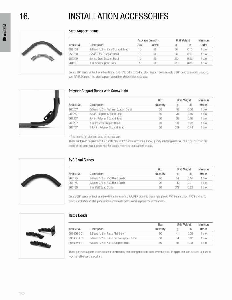
1.36
RH a
nd S
IM
Steel Support Bends
Package Quantity Unit Weight Minimum
Article No. Description Box Carton g lb Order
258408 3/8 and 1/2 in. Steel Support Bend 10 50 50 0.10 1 box
258798 5/8 in. Steel Support Bend 10 50 90 0.19 1 box
257249 3/4 in. Steel Support Bend 10 50 150 0.32 1 box
261153 1 in. Steel Support Bend 5 50 380 0.84 1 box
Create 90° bends without an elbow fitting. 3/8, 1/2, 5/8 and 3/4 in. steel support bends create a 90° bend by quickly snapping
over RAUPEX pipe. 1 in. steel support bends (not shown) slide onto pipe.
Polymer Support Bends with Screw Hole
Box Unit Weight Minimum
Article No. Description Quantity g lb Order
266207 3/8 and 1/2 in. Polymer Support Bend 50 40 0.08 1 box
266217+ 5/8 in. Polymer Support Bend 50 70 0.16 1 box
266227 3/4 in. Polymer Support Bend 50 70 0.16 1 box
266237 1 in. Polymer Support Bend 50 100 0.22 1 box
266727 1 1/4 in. Polymer Support Bend 50 200 0.44 1 box
+ This item is not stocked. Lead times may vary.
These reinforced polymer bend supports create 90º bends without an elbow, quickly snapping over RAUPEX pipe. "Ear" on the
inside of the bend has a screw hole for secure mounting to a support or stud.
PVC Bend Guides
Box Unit Weight Minimum
Article No. Description Quantity g lb Order
266170 3/8 and 1/2 in. PVC Bend Guide 40 64 0.14 1 box
266175 5/8 and 3/4 in. PVC Bend Guide 30 142 0.31 1 box
266180 1 in. PVC Bend Guide 20 378 0.83 1 box
Create 90° bends without an elbow fitting by inserting RAUPEX pipe into these rigid plastic PVC bend guides. PVC bend guides
provide protection at slab penetrations and create professional appearance at manifolds.
Rattle Bends
Box Unit Weight Minimum
Article No. Description Quantity g lb Order
298676-001 3/8 and 1/2 in. Rattle Nail Bend 50 41 0.09 1 box
298686-001 3/8 and 1/2 in. Rattle Screw Support Bend 50 54 0.12 1 box
298696-001 3/8 and 1/2 in. Rattle Support Bend 50 36 0.08 1 box
These polymer support bends create a 90º bend by first sliding the rattle bend over the pipe. The pipe then can be bent in place to
lock the rattle bend in position.
16. installation accessories
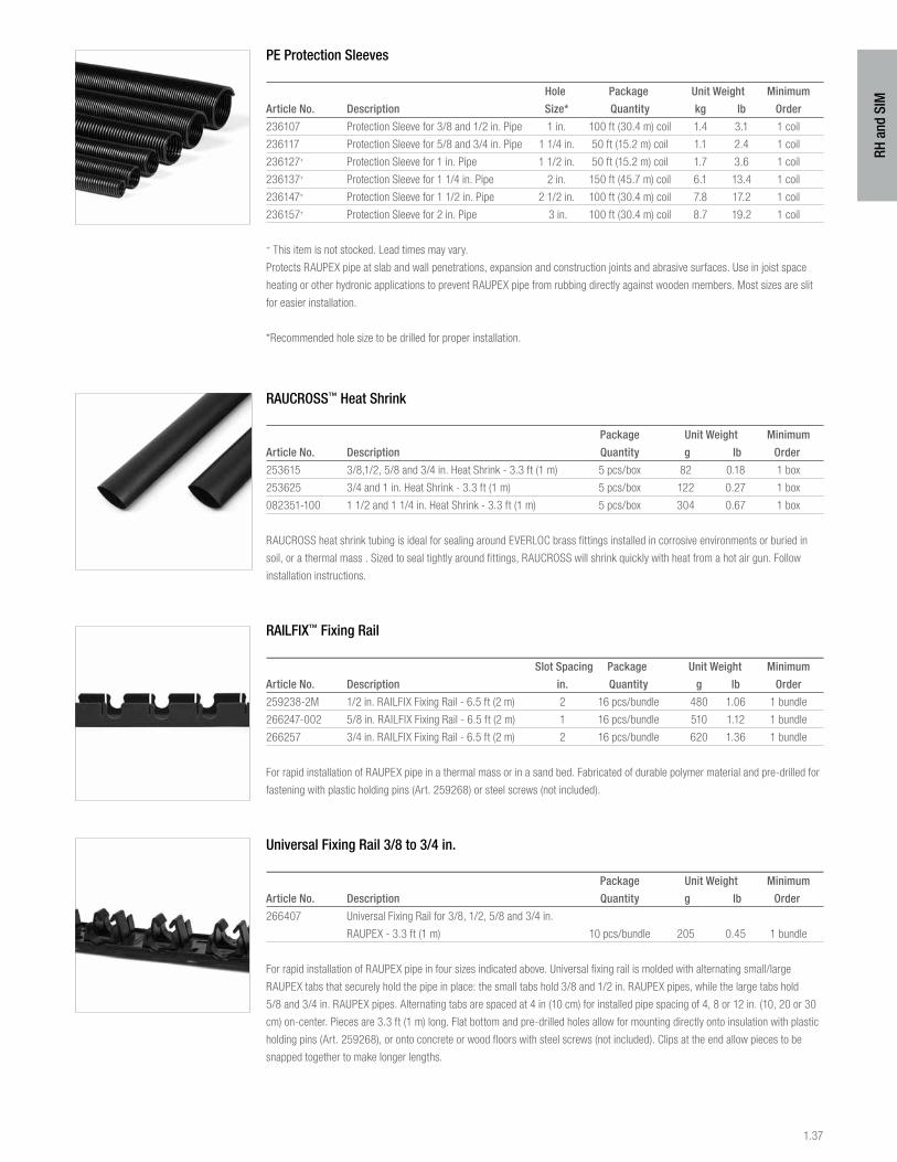
1.37
RH a
nd S
IM
PE Protection Sleeves
Hole Package Unit Weight Minimum
Article No. Description Size* Quantity kg lb Order
236107 Protection Sleeve for 3/8 and 1/2 in. Pipe 1 in. 100 ft (30.4 m) coil 1.4 3.1 1 coil
236117 Protection Sleeve for 5/8 and 3/4 in. Pipe 1 1/4 in. 50 ft (15.2 m) coil 1.1 2.4 1 coil
236127+ Protection Sleeve for 1 in. Pipe 1 1/2 in. 50 ft (15.2 m) coil 1.7 3.6 1 coil
236137+ Protection Sleeve for 1 1/4 in. Pipe 2 in. 150 ft (45.7 m) coil 6.1 13.4 1 coil
236147+ Protection Sleeve for 1 1/2 in. Pipe 2 1/2 in. 100 ft (30.4 m) coil 7.8 17.2 1 coil
236157+ Protection Sleeve for 2 in. Pipe 3 in. 100 ft (30.4 m) coil 8.7 19.2 1 coil
+ This item is not stocked. Lead times may vary.
Protects RAUPEX pipe at slab and wall penetrations, expansion and construction joints and abrasive surfaces. Use in joist space
heating or other hydronic applications to prevent RAUPEX pipe from rubbing directly against wooden members. Most sizes are slit
for easier installation.
*Recommended hole size to be drilled for proper installation.
RAUCROSS™ Heat Shrink
Package Unit Weight Minimum
Article No. Description Quantity g lb Order
253615 3/8,1/2, 5/8 and 3/4 in. Heat Shrink - 3.3 ft (1 m) 5 pcs/box 82 0.18 1 box
253625 3/4 and 1 in. Heat Shrink - 3.3 ft (1 m) 5 pcs/box 122 0.27 1 box
082351-100 1 1/2 and 1 1/4 in. Heat Shrink - 3.3 ft (1 m) 5 pcs/box 304 0.67 1 box
RAUCROSS heat shrink tubing is ideal for sealing around EVERLOC brass fittings installed in corrosive environments or buried in
soil, or a thermal mass . Sized to seal tightly around fittings, RAUCROSS will shrink quickly with heat from a hot air gun. Follow
installation instructions.
RAILFIX™ Fixing Rail
Slot Spacing Package Unit Weight Minimum
Article No. Description in. Quantity g lb Order
259238-2M 1/2 in. RAILFIX Fixing Rail - 6.5 ft (2 m) 2 16 pcs/bundle 480 1.06 1 bundle
266247-002 5/8 in. RAILFIX Fixing Rail - 6.5 ft (2 m) 1 16 pcs/bundle 510 1.12 1 bundle
266257 3/4 in. RAILFIX Fixing Rail - 6.5 ft (2 m) 2 16 pcs/bundle 620 1.36 1 bundle
For rapid installation of RAUPEX pipe in a thermal mass or in a sand bed. Fabricated of durable polymer material and pre-drilled for
fastening with plastic holding pins (Art. 259268) or steel screws (not included).
Universal Fixing Rail 3/8 to 3/4 in.
Package Unit Weight Minimum
Article No. Description Quantity g lb Order
266407 Universal Fixing Rail for 3/8, 1/2, 5/8 and 3/4 in.
RAUPEX - 3.3 ft (1 m) 10 pcs/bundle 205 0.45 1 bundle
For rapid installation of RAUPEX pipe in four sizes indicated above. Universal fixing rail is molded with alternating small/large
RAUPEX tabs that securely hold the pipe in place: the small tabs hold 3/8 and 1/2 in. RAUPEX pipes, while the large tabs hold
5/8 and 3/4 in. RAUPEX pipes. Alternating tabs are spaced at 4 in (10 cm) for installed pipe spacing of 4, 8 or 12 in. (10, 20 or 30
cm) on-center. Pieces are 3.3 ft (1 m) long. Flat bottom and pre-drilled holes allow for mounting directly onto insulation with plastic
holding pins (Art. 259268), or onto concrete or wood floors with steel screws (not included). Clips at the end allow pieces to be
snapped together to make longer lengths.
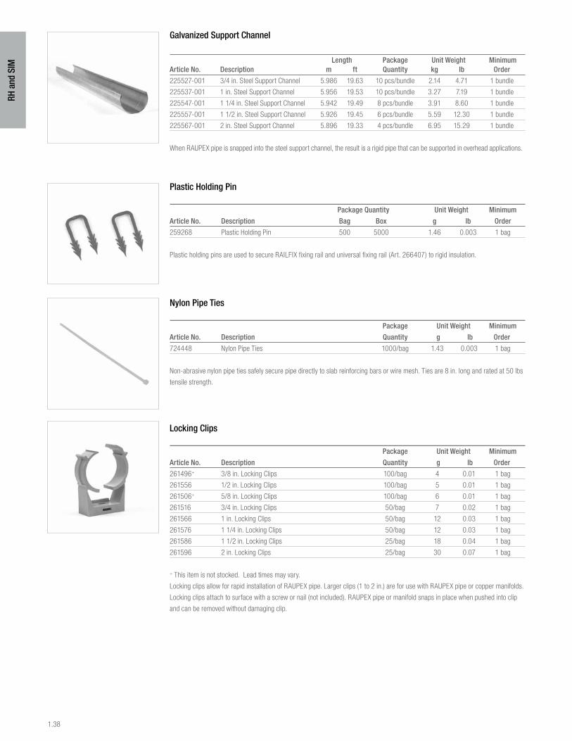
1.38
RH a
nd S
IM
Galvanized Support Channel
Length Package Unit Weight MinimumArticle No. Description m ft Quantity kg lb Order
225527-001 3/4 in. Steel Support Channel 5.986 19.63 10 pcs/bundle 2.14 4.71 1 bundle
225537-001 1 in. Steel Support Channel 5.956 19.53 10 pcs/bundle 3.27 7.19 1 bundle
225547-001 1 1/4 in. Steel Support Channel 5.942 19.49 8 pcs/bundle 3.91 8.60 1 bundle
225557-001 1 1/2 in. Steel Support Channel 5.926 19.45 6 pcs/bundle 5.59 12.30 1 bundle
225567-001 2 in. Steel Support Channel 5.896 19.33 4 pcs/bundle 6.95 15.29 1 bundle
When RAUPEX pipe is snapped into the steel support channel, the result is a rigid pipe that can be supported in overhead applications.
Plastic Holding Pin
Package Quantity Unit Weight Minimum
Article No. Description Bag Box g lb Order
259268 Plastic Holding Pin 500 5000 1.46 0.003 1 bag
Plastic holding pins are used to secure RAILFIX fixing rail and universal fixing rail (Art. 266407) to rigid insulation.
Nylon Pipe Ties
Package Unit Weight Minimum
Article No. Description Quantity g lb Order
724448 Nylon Pipe Ties 1000/bag 1.43 0.003 1 bag
Non-abrasive nylon pipe ties safely secure pipe directly to slab reinforcing bars or wire mesh. Ties are 8 in. long and rated at 50 lbs
tensile strength.
Locking Clips
Package Unit Weight Minimum
Article No. Description Quantity g lb Order
261496+ 3/8 in. Locking Clips 100/bag 4 0.01 1 bag
261556 1/2 in. Locking Clips 100/bag 5 0.01 1 bag
261506+ 5/8 in. Locking Clips 100/bag 6 0.01 1 bag
261516 3/4 in. Locking Clips 50/bag 7 0.02 1 bag
261566 1 in. Locking Clips 50/bag 12 0.03 1 bag
261576 1 1/4 in. Locking Clips 50/bag 12 0.03 1 bag
261586 1 1/2 in. Locking Clips 25/bag 18 0.04 1 bag
261596 2 in. Locking Clips 25/bag 30 0.07 1 bag
+ This item is not stocked. Lead times may vary.
Locking clips allow for rapid installation of RAUPEX pipe. Larger clips (1 to 2 in.) are for use with RAUPEX pipe or copper manifolds.
Locking clips attach to surface with a screw or nail (not included). RAUPEX pipe or manifold snaps in place when pushed into clip
and can be removed without damaging clip.
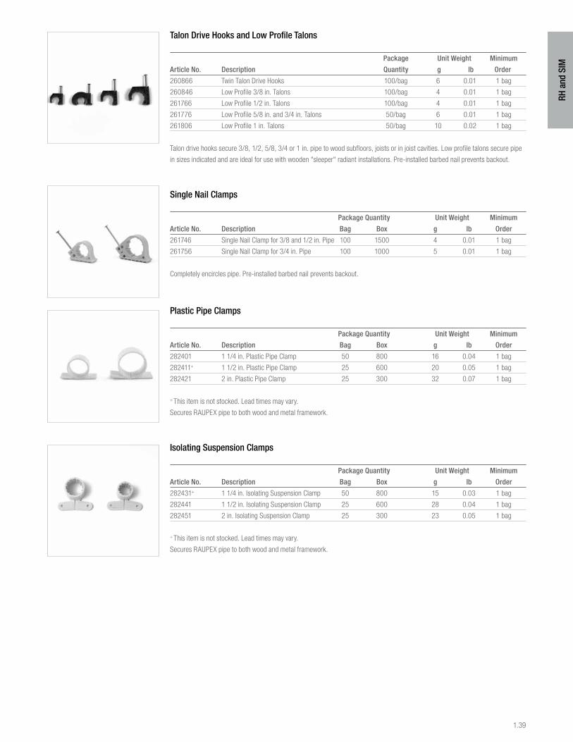
1.39
RH a
nd S
IM
Talon Drive Hooks and Low Profile Talons
Package Unit Weight Minimum
Article No. Description Quantity g lb Order
260866 Twin Talon Drive Hooks 100/bag 6 0.01 1 bag
260846 Low Profile 3/8 in. Talons 100/bag 4 0.01 1 bag
261766 Low Profile 1/2 in. Talons 100/bag 4 0.01 1 bag
261776 Low Profile 5/8 in. and 3/4 in. Talons 50/bag 6 0.01 1 bag
261806 Low Profile 1 in. Talons 50/bag 10 0.02 1 bag
Talon drive hooks secure 3/8, 1/2, 5/8, 3/4 or 1 in. pipe to wood subfloors, joists or in joist cavities. Low profile talons secure pipe
in sizes indicated and are ideal for use with wooden "sleeper" radiant installations. Pre-installed barbed nail prevents backout.
Single Nail Clamps
Package Quantity Unit Weight Minimum
Article No. Description Bag Box g lb Order
261746 Single Nail Clamp for 3/8 and 1/2 in. Pipe 100 1500 4 0.01 1 bag
261756 Single Nail Clamp for 3/4 in. Pipe 100 1000 5 0.01 1 bag
Completely encircles pipe. Pre-installed barbed nail prevents backout.
Plastic Pipe Clamps
Package Quantity Unit Weight Minimum
Article No. Description Bag Box g lb Order
282401 1 1/4 in. Plastic Pipe Clamp 50 800 16 0.04 1 bag
282411+ 1 1/2 in. Plastic Pipe Clamp 25 600 20 0.05 1 bag
282421 2 in. Plastic Pipe Clamp 25 300 32 0.07 1 bag
+ This item is not stocked. Lead times may vary.
Secures RAUPEX pipe to both wood and metal framework.
Isolating Suspension Clamps
Package Quantity Unit Weight Minimum
Article No. Description Bag Box g lb Order
282431+ 1 1/4 in. Isolating Suspension Clamp 50 800 15 0.03 1 bag
282441 1 1/2 in. Isolating Suspension Clamp 25 600 28 0.04 1 bag
282451 2 in. Isolating Suspension Clamp 25 300 23 0.05 1 bag
+ This item is not stocked. Lead times may vary.
Secures RAUPEX pipe to both wood and metal framework.
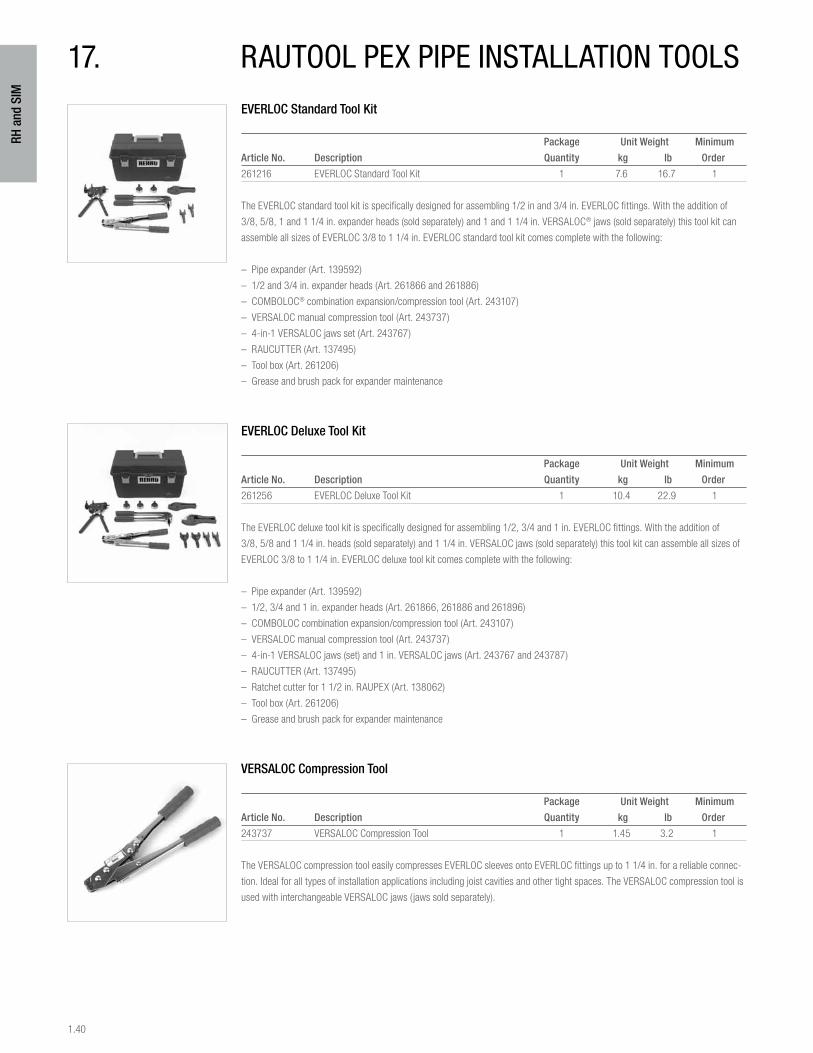
1.40
RH a
nd S
IM
EVERLOC Standard Tool Kit
Package Unit Weight Minimum
Article No. Description Quantity kg lb Order
261216 EVERLOC Standard Tool Kit 1 7.6 16.7 1
The EVERLOC standard tool kit is specifically designed for assembling 1/2 in and 3/4 in. EVERLOC fittings. With the addition of
3/8, 5/8, 1 and 1 1/4 in. expander heads (sold separately) and 1 and 1 1/4 in. VERSALOC® jaws (sold separately) this tool kit can
assemble all sizes of EVERLOC 3/8 to 1 1/4 in. EVERLOC standard tool kit comes complete with the following:
– Pipe expander (Art. 139592)
– 1/2 and 3/4 in. expander heads (Art. 261866 and 261886)
– COMBOLOC® combination expansion/compression tool (Art. 243107)
– VERSALOC manual compression tool (Art. 243737)
– 4-in-1 VERSALOC jaws set (Art. 243767)
– RAUCUTTER (Art. 137495)
– Tool box (Art. 261206)
– Grease and brush pack for expander maintenance
EVERLOC Deluxe Tool Kit
Package Unit Weight Minimum
Article No. Description Quantity kg lb Order
261256 EVERLOC Deluxe Tool Kit 1 10.4 22.9 1
The EVERLOC deluxe tool kit is specifically designed for assembling 1/2, 3/4 and 1 in. EVERLOC fittings. With the addition of
3/8, 5/8 and 1 1/4 in. heads (sold separately) and 1 1/4 in. VERSALOC jaws (sold separately) this tool kit can assemble all sizes of
EVERLOC 3/8 to 1 1/4 in. EVERLOC deluxe tool kit comes complete with the following:
– Pipe expander (Art. 139592)
– 1/2, 3/4 and 1 in. expander heads (Art. 261866, 261886 and 261896)
– COMBOLOC combination expansion/compression tool (Art. 243107)
– VERSALOC manual compression tool (Art. 243737)
– 4-in-1 VERSALOC jaws (set) and 1 in. VERSALOC jaws (Art. 243767 and 243787)
– RAUCUTTER (Art. 137495)
– Ratchet cutter for 1 1/2 in. RAUPEX (Art. 138062)
– Tool box (Art. 261206)
– Grease and brush pack for expander maintenance
VERSALOC Compression Tool
Package Unit Weight Minimum
Article No. Description Quantity kg lb Order
243737 VERSALOC Compression Tool 1 1.45 3.2 1
The VERSALOC compression tool easily compresses EVERLOC sleeves onto EVERLOC fittings up to 1 1/4 in. for a reliable connec-
tion. Ideal for all types of installation applications including joist cavities and other tight spaces. The VERSALOC compression tool is
used with interchangeable VERSALOC jaws (jaws sold separately).
17. rautool peX pipe installation tools
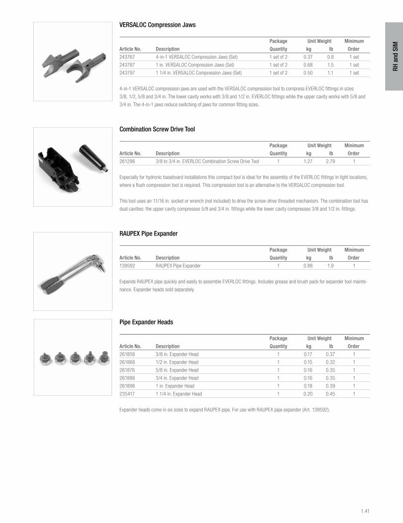
1.41
RH a
nd S
IM
VERSALOC Compression Jaws
Package Unit Weight Minimum
Article No. Description Quantity kg lb Order
243767 4-in-1 VERSALOC Compression Jaws (Set) 1 set of 2 0.37 0.8 1 set
243787 1 in. VERSALOC Compression Jaws (Set) 1 set of 2 0.68 1.5 1 set
243797 1 1/4 in. VERSALOC Compression Jaws (Set) 1 set of 2 0.50 1.1 1 set
4-in-1 VERSALOC compression jaws are used with the VERSALOC compression tool to compress EVERLOC fittings in sizes
3/8, 1/2, 5/8 and 3/4 in. The lower cavity works with 3/8 and 1/2 in. EVERLOC fittings while the upper cavity works with 5/8 and
3/4 in. The 4-in-1 jaws reduce switching of jaws for common fitting sizes.
Combination Screw Drive Tool
Package Unit Weight Minimum
Article No. Description Quantity kg lb Order
261296 3/8 to 3/4 in. EVERLOC Combination Screw Drive Tool 1 1.27 2.79 1
Especially for hydronic baseboard installations this compact tool is ideal for the assembly of the EVERLOC fittings in tight locations,
where a flush compression tool is required. This compression tool is an alternative to the VERSALOC compression tool.
This tool uses an 11/16 in. socket or wrench (not included) to drive the screw-drive threaded mechanism. The combination tool has
dual cavities: the upper cavity compresses 5/8 and 3/4 in. fittings while the lower cavity compresses 3/8 and 1/2 in. fittings.
RAUPEX Pipe Expander
Package Unit Weight Minimum
Article No. Description Quantity kg lb Order
139592 RAUPEX Pipe Expander 1 0.88 1.9 1
Expands RAUPEX pipe quickly and easily to assemble EVERLOC fittings. Includes grease and brush pack for expander tool mainte-
nance. Expander heads sold separately.
Pipe Expander Heads
Package Unit Weight Minimum
Article No. Description Quantity kg lb Order
261856 3/8 in. Expander Head 1 0.17 0.37 1
261866 1/2 in. Expander Head 1 0.15 0.32 1
261876 5/8 in. Expander Head 1 0.16 0.35 1
261886 3/4 in. Expander Head 1 0.16 0.35 1
261896 1 in. Expander Head 1 0.18 0.39 1
235417 1 1/4 in. Expander Head 1 0.20 0.45 1
Expander heads come in six sizes to expand RAUPEX pipe. For use with RAUPEX pipe expander (Art. 139592).
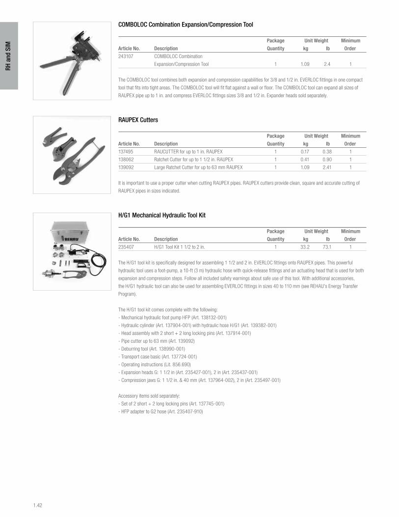
1.42
RH a
nd S
IM
COMBOLOC Combination Expansion/Compression Tool
Package Unit Weight Minimum
Article No. Description Quantity kg lb Order
243107 COMBOLOC Combination
Expansion/Compression Tool 1 1.09 2.4 1
The COMBOLOC tool combines both expansion and compression capabilities for 3/8 and 1/2 in. EVERLOC fittings in one compact
tool that fits into tight areas. The COMBOLOC tool will fit flat against a wall or floor. The COMBOLOC tool can expand all sizes of
RAUPEX pipe up to 1 in. and compress EVERLOC fittings sizes 3/8 and 1/2 in. Expander heads sold separately.
RAUPEX Cutters
Package Unit Weight Minimum
Article No. Description Quantity kg lb Order
137495 RAUCUTTER for up to 1 in. RAUPEX 1 0.17 0.38 1
138062 Ratchet Cutter for up to 1 1/2 in. RAUPEX 1 0.41 0.90 1
139092 Large Ratchet Cutter for up to 63 mm RAUPEX 1 1.09 2.41 1
It is important to use a proper cutter when cutting RAUPEX pipes. RAUPEX cutters provide clean, square and accurate cutting of
RAUPEX pipes in sizes indicated.
H/G1 Mechanical Hydraulic Tool Kit
Package Unit Weight Minimum
Article No. Description Quantity kg lb Order
235407 H/G1 Tool Kit 1 1/2 to 2 in. 1 33.2 73.1 1
The H/G1 tool kit is specifically designed for assembling 1 1/2 and 2 in. EVERLOC fittings onto RAUPEX pipes. This powerful
hydraulic tool uses a foot-pump, a 10-ft (3 m) hydraulic hose with quick-release fittings and an actuating head that is used for both
expansion and compression steps. Follow all included safety warnings about safe use of this tool. With additional accessories,
the H/G1 hydraulic tool can also be used for assembling EVERLOC fittings in sizes 40 to 110 mm (see REHAU's Energy Transfer
Program).
The H/G1 tool kit comes complete with the following:
- Mechanical hydraulic foot pump HFP (Art. 138132-001)
- Hydraulic cylinder (Art. 137904-001) with hydraulic hose H/G1 (Art. 139382-001)
- Head assembly with 2 short + 2 long locking pins (Art. 137914-001)
- Pipe cutter up to 63 mm (Art. 139092)
- Deburring tool (Art. 138990-001)
- Transport case basic (Art. 137724-001)
- Operating instructions (Lit. 856.690)
- Expansion heads G: 1 1/2 in (Art. 235427-001), 2 in (Art. 235437-001)
- Compression jaws G: 1 1/2 in. & 40 mm (Art. 137964-002), 2 in (Art. 235497-001)
Accessory items sold separately:
- Set of 2 short + 2 long locking pins (Art. 137745-001)
- HFP adapter to G2 hose (Art. 235407-910)
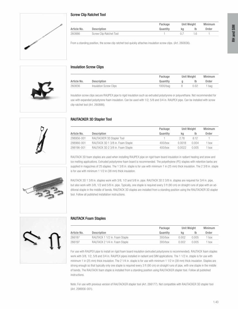
1.43
RH a
nd S
IM
Screw Clip Ratchet Tool
Package Unit Weight Minimum
Article No. Description Quantity kg lb Order
260886 Screw Clip Ratchet Tool 1 0.7 1.6 1
From a standing position, the screw clip ratchet tool quickly attaches insulation screw clips. (Art. 260836).
Insulation Screw Clips
Package Unit Weight Minimum
Article No. Description Quantity g lb Order
260836 Insulation Screw Clips 1000/bag 8 0.02 1 bag
Insulation screw clips secure RAUPEX pipe to rigid insulation such as extruded polystyrene or polyurethane. Not recommended for
use with expanded polystyrene foam insulation. Can be used with 1/2, 5/8 and 3/4 in. RAUPEX pipe. Can be installed with screw
clip ratchet tool (Art. 260886).
RAUTACKER 3D Stapler Tool
Package Unit Weight Minimum
Article No. Description Quantity kg lb Order
298956-001 RAUTACKER 3D Stapler Tool 1 2.78 6.12 1
298966-001 RAUTACK 3D 1 3/8 in. Foam Staple 400/box 0.0018 0.004 1 box
298196-001 RAUTACK 3D 2 3/8 in. Foam Staple 400/box 0.0022 0.005 1 box
RAUTACK 3D foam staples are used when installing RAUPEX pipe on rigid foam board insulation in radiant heating and snow and
ice melting applications. Extruded polystyrene foam board is recommended. The polyethylene (PE) staples with retention barbs are
supplied in magazines of 25 staples. The 1 3/8 in. staple is for use with minimum 1 in (25 mm) thick insulation. The 2 3/8 in. staple
is for use with minimum 1 1/2 in (38 mm) thick insulation.
RAUTACK 3D 1 3/8 in. staples work with 3/8, 1/2 and 5/8 in. pipe. RAUTACK 3D 2 3/8 in. staples are required for 3/4 in. pipe,
but also work with 3/8, 1/2 and 5/8 in. pipe. Typically, one staple is required every 3 ft (90 cm) on straight runs of pipe with an ad-
ditional staple in the middle of bends. RAUTACK 3D staples are installed from a standing position using the RAUTACKER 3D stapler
tool. Follow all published installation instructions.
RAUTACK Foam Staples
Package Unit Weight Minimum
Article No. Description Quantity kg lb Order
266187 RAUTACK 1 1/2 in. Foam Staple 300/box 0.002 0.005 1 box
266197 RAUTACK 2 1/4 in. Foam Staple 300/box 0.002 0.005 1 box
For use with RAUPEX pipe to install on rigid foam board insulation (extruded polystyrene is recommended). RAUTACK foam staples
work with 3/8, 1/2, 5/8 and 3/4 in. RAUPEX pipes installed in radiant and SIM applications. The 1 1/2 in. staple is for use with
minimum 1 in (25 mm) thick insulation. The 2 1/4 in. staple is for use with minimum 1 1/2 in (38 mm) thick insulation. Staples are
strong enough so that typically only one staple is required every 3 ft (90 cm) on straight runs of pipe, with one staple in the middle
of bends. The RAUTACK foam staple is installed from a standing position using RAUTACKER stapler tool. Follow all published
instructions.
Note: For use with previous version of RAUTACKER stapler tool (Art. 266177). Not compatible with RAUTACKER 3D stapler tool
(Art. 298956-001).
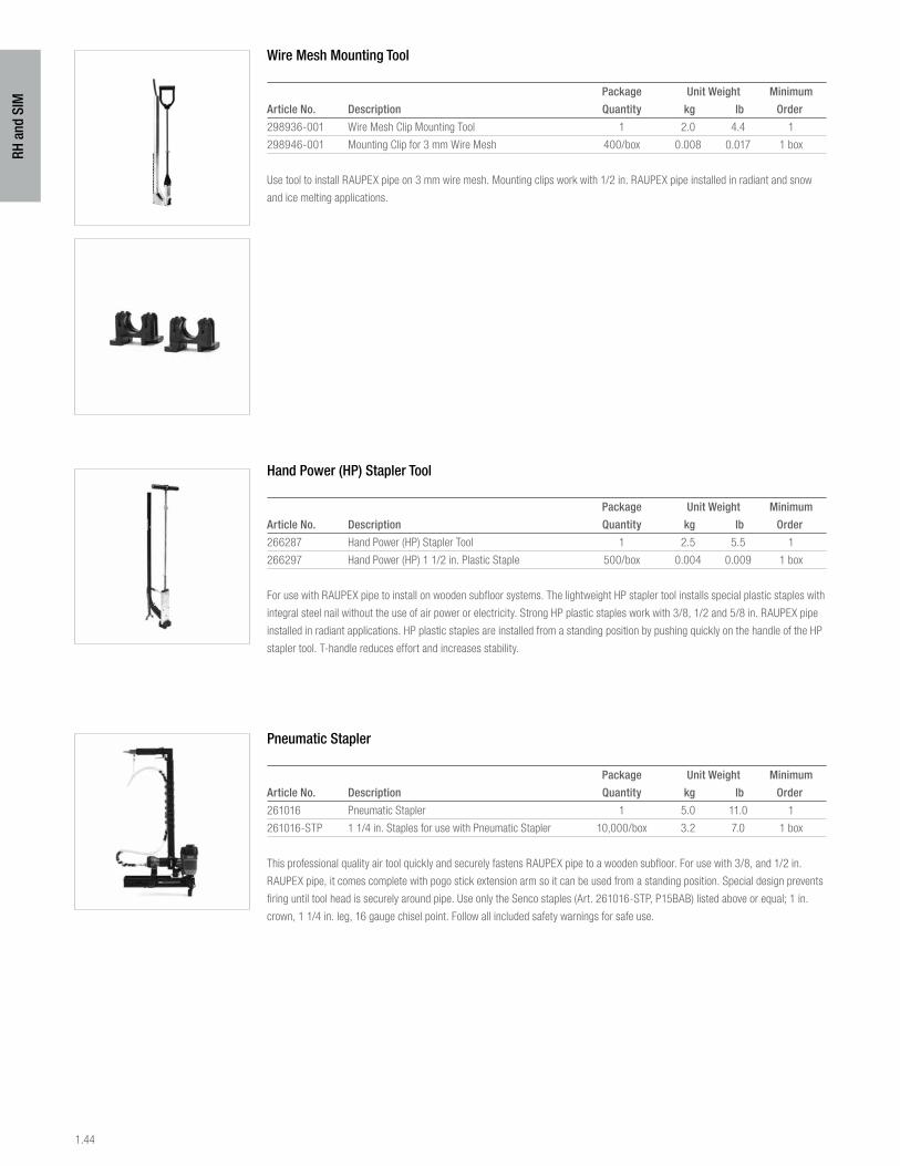
1.44
RH a
nd S
IM
Wire Mesh Mounting Tool
Package Unit Weight Minimum
Article No. Description Quantity kg lb Order
298936-001 Wire Mesh Clip Mounting Tool 1 2.0 4.4 1
298946-001 Mounting Clip for 3 mm Wire Mesh 400/box 0.008 0.017 1 box
Use tool to install RAUPEX pipe on 3 mm wire mesh. Mounting clips work with 1/2 in. RAUPEX pipe installed in radiant and snow
and ice melting applications.
Hand Power (HP) Stapler Tool
Package Unit Weight Minimum
Article No. Description Quantity kg lb Order
266287 Hand Power (HP) Stapler Tool 1 2.5 5.5 1
266297 Hand Power (HP) 1 1/2 in. Plastic Staple 500/box 0.004 0.009 1 box
For use with RAUPEX pipe to install on wooden subfloor systems. The lightweight HP stapler tool installs special plastic staples with
integral steel nail without the use of air power or electricity. Strong HP plastic staples work with 3/8, 1/2 and 5/8 in. RAUPEX pipe
installed in radiant applications. HP plastic staples are installed from a standing position by pushing quickly on the handle of the HP
stapler tool. T-handle reduces effort and increases stability.
Pneumatic Stapler
Package Unit Weight Minimum
Article No. Description Quantity kg lb Order
261016 Pneumatic Stapler 1 5.0 11.0 1
261016-STP 1 1/4 in. Staples for use with Pneumatic Stapler 10,000/box 3.2 7.0 1 box
This professional quality air tool quickly and securely fastens RAUPEX pipe to a wooden subfloor. For use with 3/8, and 1/2 in.
RAUPEX pipe, it comes complete with pogo stick extension arm so it can be used from a standing position. Special design prevents
firing until tool head is securely around pipe. Use only the Senco staples (Art. 261016-STP, P15BAB) listed above or equal; 1 in.
crown, 1 1/4 in. leg, 16 gauge chisel point. Follow all included safety warnings for safe use.
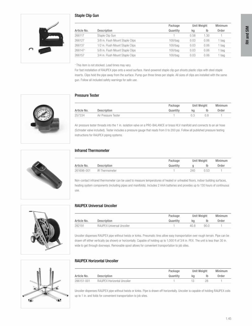
1.45
RH a
nd S
IM
Staple Clip Gun
Package Unit Weight Minimum
Article No. Description Quantity kg lb Order
266117 Staple Clip Gun 1 0.58 1.30 1
266127 3/8 in. Flush Mount Staple Clips 100/bag 0.03 0.06 1 bag
266137 1/2 in. Flush Mount Staple Clips 100/bag 0.03 0.06 1 bag
266147+ 5/8 in. Flush Mount Staple Clips 100/bag 0.03 0.06 1 bag
266157 3/4 in. Flush Mount Staple Clips 100/bag 0.03 0.06 1 bag
+ This item is not stocked. Lead times may vary.
For fast installation of RAUPEX pipe onto a wood surface. Hand-powered staple clip gun shoots plastic clips with steel staple
inserts. Clips hold the pipe away from the surface. Pump gun three times per staple. All sizes of clips are installed with the same
gun. Follow all included safety warnings for safe use.
Pressure Tester
Package Unit Weight Minimum
Article No. Description Quantity kg lb Order
257334 Air Pressure Tester 1 0.3 0.8 1
Air pressure tester threads into the 1 in. isolation valve on a PRO-BALANCE or brass HLV manifold and connects to an air hose
(Schrader valve included). Tester includes a pressure gauge that reads from 0 to 200 psi. Follow all published pressure testing
instructions for RAUPEX piping systems.
Infrared Thermometer
Package Unit Weight Minimum
Article No. Description Quantity g lb Order
261696-001 IR Thermometer 1 240 0.53 1
Non-contact infrared thermometer can be used to measure temperatures of heated or unheated floors, indoor building surfaces,
heating system components (including pipes and manifolds). Includes 2 AAA batteries and provides up to 130 hours of continuous
use.
RAUPEX Universal Uncoiler
Package Unit Weight Minimum
Article No. Description Quantity kg lb Order
282191 RAUPEX Universal Uncoiler 1 40.8 90.0 1
Uncoiler dispenses RAUPEX pipe without twists or kinks. Pneumatic tires allow easy transportation over rough terrain. Pipe can be
drawn off either vertically (as shown) or horizontally. Capable of holding up to 1,000 ft of 3/4 in. PEX. The unit is less than 30 in.
wide to get through doorways. Removable spool allows for convenient transportation to job sites.
RAUPEX Horizontal Uncoiler
Package Unit Weight Minimum
Article No. Description Quantity kg lb Order
286151-001 RAUPEX Horizontal Uncoiler 1 13 28 1
Uncoiler dispenses RAUPEX pipe without twists or kinks. Pipe is drawn off horizontally. Uncoiler is capable of holding RAUPEX coils
up to 1 in. and folds for convenient transportation to job sites.
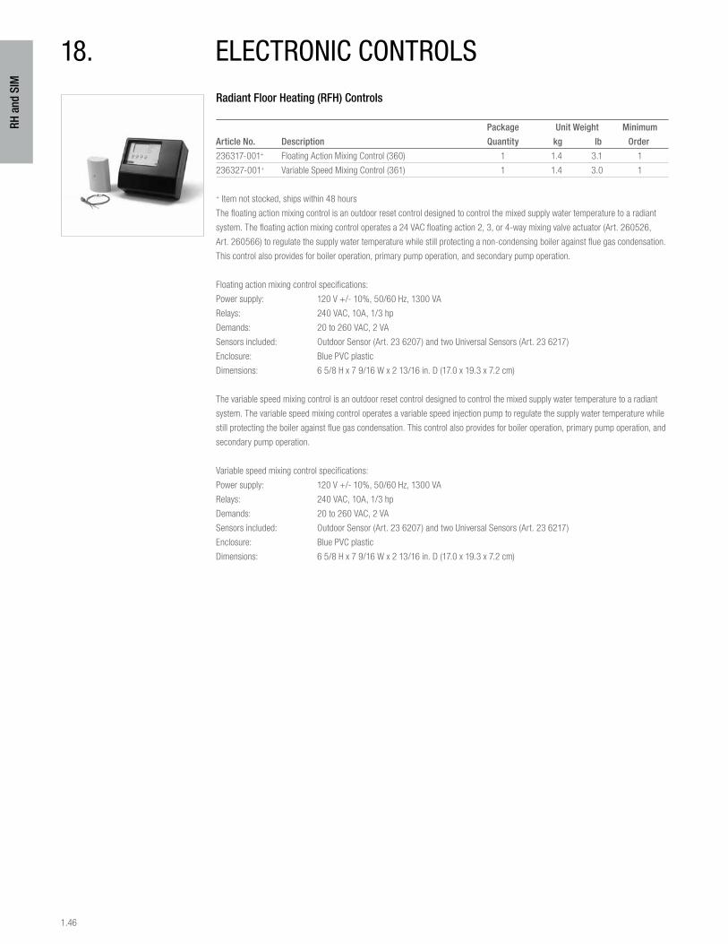
1.46
RH a
nd S
IM
Radiant Floor Heating (RFH) Controls
Package Unit Weight Minimum
Article No. Description Quantity kg lb Order
236317-001+ Floating Action Mixing Control (360) 1 1.4 3.1 1
236327-001+ Variable Speed Mixing Control (361) 1 1.4 3.0 1
+ Item not stocked, ships within 48 hours
The floating action mixing control is an outdoor reset control designed to control the mixed supply water temperature to a radiant
system. The floating action mixing control operates a 24 VAC floating action 2, 3, or 4-way mixing valve actuator (Art. 260526,
Art. 260566) to regulate the supply water temperature while still protecting a non-condensing boiler against flue gas condensation.
This control also provides for boiler operation, primary pump operation, and secondary pump operation.
Floating action mixing control specifications:
Power supply: 120 V +/- 10%, 50/60 Hz, 1300 VA
Relays: 240 VAC, 10A, 1/3 hp
Demands: 20 to 260 VAC, 2 VA
Sensors included: Outdoor Sensor (Art. 23 6207) and two Universal Sensors (Art. 23 6217)
Enclosure: Blue PVC plastic
Dimensions: 6 5/8 H x 7 9/16 W x 2 13/16 in. D (17.0 x 19.3 x 7.2 cm)
The variable speed mixing control is an outdoor reset control designed to control the mixed supply water temperature to a radiant
system. The variable speed mixing control operates a variable speed injection pump to regulate the supply water temperature while
still protecting the boiler against flue gas condensation. This control also provides for boiler operation, primary pump operation, and
secondary pump operation.
Variable speed mixing control specifications:
Power supply: 120 V +/- 10%, 50/60 Hz, 1300 VA
Relays: 240 VAC, 10A, 1/3 hp
Demands: 20 to 260 VAC, 2 VA
Sensors included: Outdoor Sensor (Art. 23 6207) and two Universal Sensors (Art. 23 6217)
Enclosure: Blue PVC plastic
Dimensions: 6 5/8 H x 7 9/16 W x 2 13/16 in. D (17.0 x 19.3 x 7.2 cm)
18. electronic controls
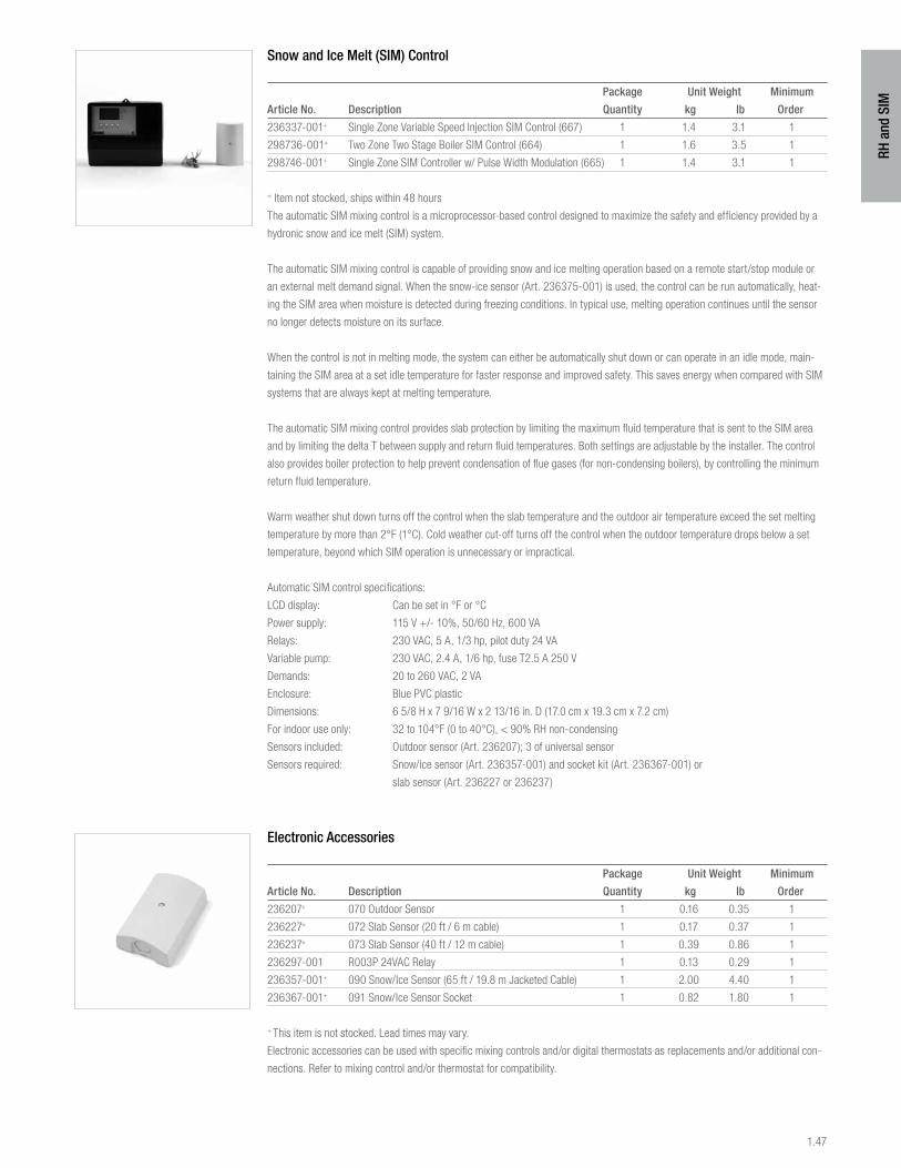
1.47
RH a
nd S
IM
Snow and Ice Melt (SIM) Control
Package Unit Weight Minimum
Article No. Description Quantity kg lb Order
236337-001+ Single Zone Variable Speed Injection SIM Control (667) 1 1.4 3.1 1
298736-001+ Two Zone Two Stage Boiler SIM Control (664) 1 1.6 3.5 1
298746-001+ Single Zone SIM Controller w/ Pulse Width Modulation (665) 1 1.4 3.1 1
+ Item not stocked, ships within 48 hours
The automatic SIM mixing control is a microprocessor-based control designed to maximize the safety and efficiency provided by a
hydronic snow and ice melt (SIM) system.
The automatic SIM mixing control is capable of providing snow and ice melting operation based on a remote start/stop module or
an external melt demand signal. When the snow-ice sensor (Art. 236375-001) is used, the control can be run automatically, heat-
ing the SIM area when moisture is detected during freezing conditions. In typical use, melting operation continues until the sensor
no longer detects moisture on its surface.
When the control is not in melting mode, the system can either be automatically shut down or can operate in an idle mode, main-
taining the SIM area at a set idle temperature for faster response and improved safety. This saves energy when compared with SIM
systems that are always kept at melting temperature.
The automatic SIM mixing control provides slab protection by limiting the maximum fluid temperature that is sent to the SIM area
and by limiting the delta T between supply and return fluid temperatures. Both settings are adjustable by the installer. The control
also provides boiler protection to help prevent condensation of flue gases (for non-condensing boilers), by controlling the minimum
return fluid temperature.
Warm weather shut down turns off the control when the slab temperature and the outdoor air temperature exceed the set melting
temperature by more than 2°F (1°C). Cold weather cut-off turns off the control when the outdoor temperature drops below a set
temperature, beyond which SIM operation is unnecessary or impractical.
Automatic SIM control specifications:
LCD display: Can be set in °F or °C
Power supply: 115 V +/- 10%, 50/60 Hz, 600 VA
Relays: 230 VAC, 5 A, 1/3 hp, pilot duty 24 VA
Variable pump: 230 VAC, 2.4 A, 1/6 hp, fuse T2.5 A 250 V
Demands: 20 to 260 VAC, 2 VA
Enclosure: Blue PVC plastic
Dimensions: 6 5/8 H x 7 9/16 W x 2 13/16 in. D (17.0 cm x 19.3 cm x 7.2 cm)
For indoor use only: 32 to 104°F (0 to 40°C), < 90% RH non-condensing
Sensors included: Outdoor sensor (Art. 236207); 3 of universal sensor
Sensors required: Snow/ice sensor (Art. 236357-001) and socket kit (Art. 236367-001) or
slab sensor (Art. 236227 or 236237)
Electronic Accessories
Package Unit Weight Minimum
Article No. Description Quantity kg lb Order
236207+ 070 Outdoor Sensor 1 0.16 0.35 1
236227+ 072 Slab Sensor (20 ft / 6 m cable) 1 0.17 0.37 1
236237+ 073 Slab Sensor (40 ft / 12 m cable) 1 0.39 0.86 1
236297-001 R003P 24VAC Relay 1 0.13 0.29 1
236357-001+ 090 Snow/Ice Sensor (65 ft / 19.8 m Jacketed Cable) 1 2.00 4.40 1
236367-001+ 091 Snow/Ice Sensor Socket 1 0.82 1.80 1
+ This item is not stocked. Lead times may vary.
Electronic accessories can be used with specific mixing controls and/or digital thermostats as replacements and/or additional con-
nections. Refer to mixing control and/or thermostat for compatibility.
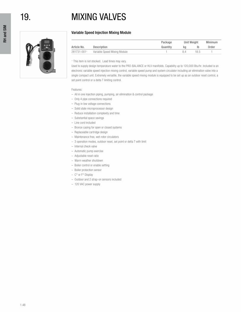
1.48
RH a
nd S
IM
Variable Speed Injection Mixing Module
Package Unit Weight Minimum
Article No. Description Quantity kg lb Order
281731-001+ Variable Speed Mixing Module 1 8.4 18.5 1
+ This item is not stocked. Lead times may vary.
Used to supply design temperature water to the PRO-BALANCE or HLV manifolds. Capability up to 120,000 Btu/hr. Included is an
electronic variable speed injection mixing control, variable speed pump and system circulator including air elimination valve into a
single compact unit. Extremely versatile, the variable speed mixing module is equipped to be set up as an outdoor reset control, a
set point control or a delta T limiting control.
Features:
– All in one injection piping, pumping, air elimination & control package
– Only 4 pipe connections required
– Plug-in low voltage connections
– Solid state microprocessor design
– Reduce installation complexity and time
– Substantial space savings
– Line cord included
– Bronze casing for open or closed systems
– Replaceable cartridge design
– Maintenance free, wet-rotor circulators
– 3 operation modes, outdoor reset, set point or delta T with limit
– Internal check valve
– Automatic pump exercise
– Adjustable reset ratio
– Warm weather shutdown
– Boiler control or enable setting
– Boiler protection sensor
– C° or F° Display
– Outdoor and 2 strap-on sensors included
– 120 VAC power supply
19. miXing valves
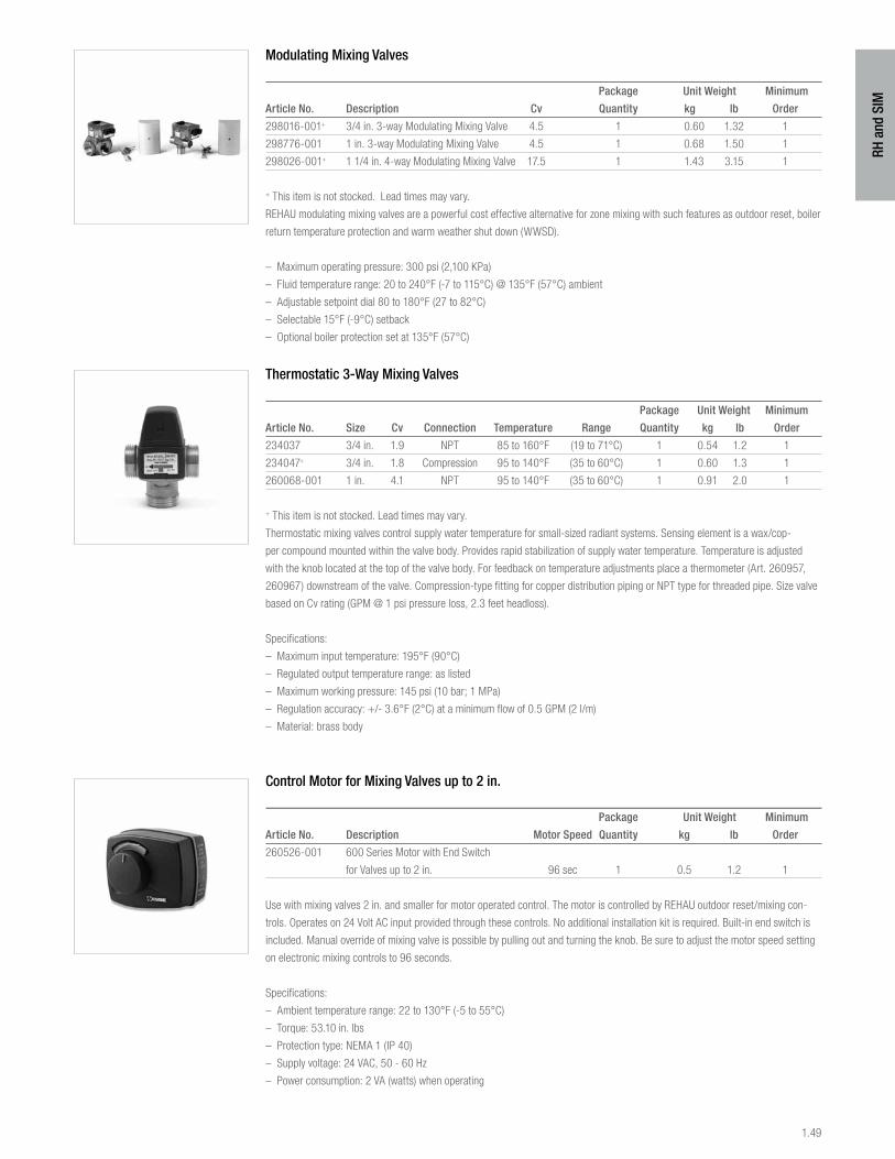
1.49
RH a
nd S
IM
Modulating Mixing Valves
Package Unit Weight Minimum
Article No. Description Cv Quantity kg lb Order
298016-001+ 3/4 in. 3-way Modulating Mixing Valve 4.5 1 0.60 1.32 1
298776-001 1 in. 3-way Modulating Mixing Valve 4.5 1 0.68 1.50 1
298026-001+ 1 1/4 in. 4-way Modulating Mixing Valve 17.5 1 1.43 3.15 1
+ This item is not stocked. Lead times may vary.
REHAU modulating mixing valves are a powerful cost effective alternative for zone mixing with such features as outdoor reset, boiler
return temperature protection and warm weather shut down (WWSD).
– Maximum operating pressure: 300 psi (2,100 KPa)
– Fluid temperature range: 20 to 240°F (-7 to 115°C) @ 135°F (57°C) ambient
– Adjustable setpoint dial 80 to 180°F (27 to 82°C)
– Selectable 15°F (-9°C) setback
– Optional boiler protection set at 135°F (57°C)
Thermostatic 3-Way Mixing Valves
Package Unit Weight Minimum
Article No. Size Cv Connection Temperature Range Quantity kg lb Order
234037 3/4 in. 1.9 NPT 85 to 160°F (19 to 71°C) 1 0.54 1.2 1
234047+ 3/4 in. 1.8 Compression 95 to 140°F (35 to 60°C) 1 0.60 1.3 1
260068-001 1 in. 4.1 NPT 95 to 140°F (35 to 60°C) 1 0.91 2.0 1
+ This item is not stocked. Lead times may vary.
Thermostatic mixing valves control supply water temperature for small-sized radiant systems. Sensing element is a wax/cop-
per compound mounted within the valve body. Provides rapid stabilization of supply water temperature. Temperature is adjusted
with the knob located at the top of the valve body. For feedback on temperature adjustments place a thermometer (Art. 260957,
260967) downstream of the valve. Compression-type fitting for copper distribution piping or NPT type for threaded pipe. Size valve
based on Cv rating (GPM @ 1 psi pressure loss, 2.3 feet headloss).
Specifications:
– Maximum input temperature: 195°F (90°C)
– Regulated output temperature range: as listed
– Maximum working pressure: 145 psi (10 bar; 1 MPa)
– Regulation accuracy: +/- 3.6°F (2°C) at a minimum flow of 0.5 GPM (2 l/m)
– Material: brass body
Control Motor for Mixing Valves up to 2 in.
Package Unit Weight Minimum
Article No. Description Motor Speed Quantity kg lb Order
260526-001 600 Series Motor with End Switch
for Valves up to 2 in. 96 sec 1 0.5 1.2 1
Use with mixing valves 2 in. and smaller for motor operated control. The motor is controlled by REHAU outdoor reset/mixing con-
trols. Operates on 24 Volt AC input provided through these controls. No additional installation kit is required. Built-in end switch is
included. Manual override of mixing valve is possible by pulling out and turning the knob. Be sure to adjust the motor speed setting
on electronic mixing controls to 96 seconds.
Specifications:
– Ambient temperature range: 22 to 130°F (-5 to 55°C)
– Torque: 53.10 in. lbs
– Protection type: NEMA 1 (IP 40)
– Supply voltage: 24 VAC, 50 - 60 Hz
– Power consumption: 2 VA (watts) when operating
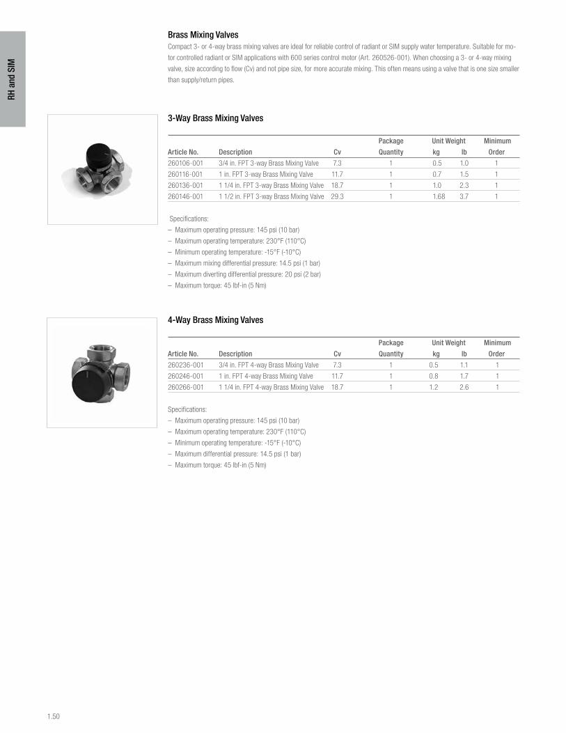
1.50
RH a
nd S
IM
Brass Mixing ValvesCompact 3- or 4-way brass mixing valves are ideal for reliable control of radiant or SIM supply water temperature. Suitable for mo-
tor controlled radiant or SIM applications with 600 series control motor (Art. 260526-001). When choosing a 3- or 4-way mixing
valve, size according to flow (Cv) and not pipe size, for more accurate mixing. This often means using a valve that is one size smaller
than supply/return pipes.
3-Way Brass Mixing Valves
Package Unit Weight Minimum
Article No. Description Cv Quantity kg lb Order
260106-001 3/4 in. FPT 3-way Brass Mixing Valve 7.3 1 0.5 1.0 1
260116-001 1 in. FPT 3-way Brass Mixing Valve 11.7 1 0.7 1.5 1
260136-001 1 1/4 in. FPT 3-way Brass Mixing Valve 18.7 1 1.0 2.3 1
260146-001 1 1/2 in. FPT 3-way Brass Mixing Valve 29.3 1 1.68 3.7 1
Specifications:
– Maximum operating pressure: 145 psi (10 bar)
– Maximum operating temperature: 230°F (110°C)
– Minimum operating temperature: -15°F (-10°C)
– Maximum mixing differential pressure: 14.5 psi (1 bar)
– Maximum diverting differential pressure: 20 psi (2 bar)
– Maximum torque: 45 lbf-in (5 Nm)
4-Way Brass Mixing Valves
Package Unit Weight Minimum
Article No. Description Cv Quantity kg lb Order
260236-001 3/4 in. FPT 4-way Brass Mixing Valve 7.3 1 0.5 1.1 1
260246-001 1 in. FPT 4-way Brass Mixing Valve 11.7 1 0.8 1.7 1
260266-001 1 1/4 in. FPT 4-way Brass Mixing Valve 18.7 1 1.2 2.6 1
Specifications:
– Maximum operating pressure: 145 psi (10 bar)
– Maximum operating temperature: 230°F (110°C)
– Minimum operating temperature: -15°F (-10°C)
– Maximum differential pressure: 14.5 psi (1 bar)
– Maximum torque: 45 lbf-in (5 Nm)
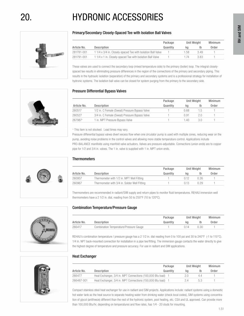
1.51
RH a
nd S
IM
20. hYdronic accessoriesPrimary/Secondary Closely-Spaced Tee with Isolation Ball Valves
Package Unit Weight Minimum
Article No. Description Quantity kg lb Order
281781-001 1 1/4 x 3/4 in. Closely-spaced Tee with Isolation Ball Valve 1 1.58 3.49 1
281791-001 1 1/4 x 1 in. Closely-spaced Tee with Isolation Ball Valve 1 1.74 3.83 1
These valves are used to connect the secondary loop (mixed temperature side) to the primary (boiler) loop. The integral closely-
spaced tee results in eliminating pressure differences in the region of the connections of the primary and secondary piping. This
results in the hydraulic isolation (separation) of the primary and secondary systems and is a professional strategy for installation of
hydronic systems. The isolation ball valve can be closed for system purging from the primary to the secondary side.
Pressure Differential Bypass Valves
Package Unit Weight Minimum
Article No. Description Quantity kg lb Order
260517 1/2 in. C Female (Sweat) Pressure Bypass Valve 1 0.68 1.5 1
260527 3/4 in. C Female (Sweat) Pressure Bypass Valve 1 0.91 2.0 1
267987+ 1 in. MPT Pressure Bypass Valve 1 1.40 3.0 1
+ This item is not stocked. Lead times may vary.
Pressure differential bypass valves divert excess flow when one circulator pump is used with multiple zones, reducing wear on the
pump, avoiding noise problems in the control valves and allowing more stable temperature control. Applications include
PRO-BALANCE manifolds using manifold valve actuators. Valves are pressure-adjustable. Connections (union ends) are to copper
pipe for 1/2 and 3/4 in. valves. The 1 in. valve is supplied with 1 in. MPT union ends.
Thermometers
Package Unit Weight Minimum
Article No. Description Quantity kg lb Order
260957 Thermometer with 1/2 in. MPT Well Fitting 1 0.12 0.26 1
260967 Thermometer with 3/4 in. Solder Well Fitting 1 0.13 0.29 1
Thermometers are recommended in radiant/SIM supply and return pipes to monitor fluid temperatures. REHAU immersion well
thermometers have a 2 1/2 in. dial, reading from 50 to 250°F (10 to 120ºC).
Combination Temperature/Pressure Gauge
Package Unit Weight Minimum
Article No. Description Quantity kg lb Order
266417 Combination Temperature/Pressure Gauge 1 0.14 0.30 1
REHAU’s combination temperature / pressure gauge has a 2 1/2 in. dial reading from 0 to 100 psi and 30 to 240°F (-1 to 115°C).
1/4 in. NPT back-mounted connection for installation in a pipe tee/fitting. The immersion gauge contacts the water directly to give
the highest degree of temperature and pressure accuracy. For use in radiant and SIM applications.
Heat Exchanger
Package Unit Weight Minimum
Article No. Description Quantity kg lb Order
266477 Heat Exchanger, 3/4 in. MPT Connections (100,000 Btu load) 1 2.0 4.4 1
266487-001 Heat Exchanger, 3/4 in. MPT Connections (150,000 Btu load) 1 2.4 5.3 1
Compact stainless steel heat exchanger for use in radiant and SIM projects. Applications include: radiant systems using a domestic
hot water tank as the heat source to separate heating water from drinking water (check local codes), SIM systems using concentra-
tion of glycol (antifreeze) different than the rest of the hydronic system, pool heating, etc. CSA and UL approved. Can provide more
than 100,000 Btu/hr, depending on temperatures and flow rates, has 1/4 - 20 studs for mounting.

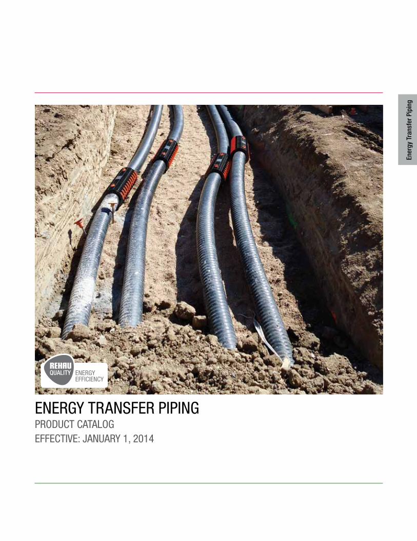
EnErgy TransfEr pipingproducT caTalogEffEcTivE: January 1, 2014
Ener
gy T
rans
fer P
ipin
g
ENERGYEFFICIENCY
2.2
Ener
gy T
rans
fer P
ipin
g
1. INSULPEX® Pipe. . . . . . . . . . . . . . . . . . . . . . . . . . . . . . . . . . 2.3
2. INSULPEX End Caps. . . . . . . . . . . . . . . . . . . . . . . . . . . . . . . 2.5
3. INSULPEX Insulation Kits . . . . . . . . . . . . . . . . . . . . . . . . . . . 2.7
4. RAUVITHERM™ Pipe . . . . . . . . . . . . . . . . . . . . . . . . . . . . . . . 2.9
5. RAUVITHERM Wall Seals and End Caps . . . . . . . . . . . . . . . 2.10
6. RAUVITHERM Shroud Kits . . . . . . . . . . . . . . . . . . . . . . . . . 2.12
7. EVERLOC® Fittings . . . . . . . . . . . . . . . . . . . . . . . . . . . . . . . 2.13
8. RAUPEX® Compression Nut Fittings. . . . . . . . . . . . . . . . . . 2.20
9. RAUTOOL™ PEX Pipe Installation Tools . . . . . . . . . . . . . . . 2.21
TablE of conTEnTs
For updates to this publication and the most current technical instructions, safety information and manufacturer’s recommendations, visit na.rehau.com/resourcecenter
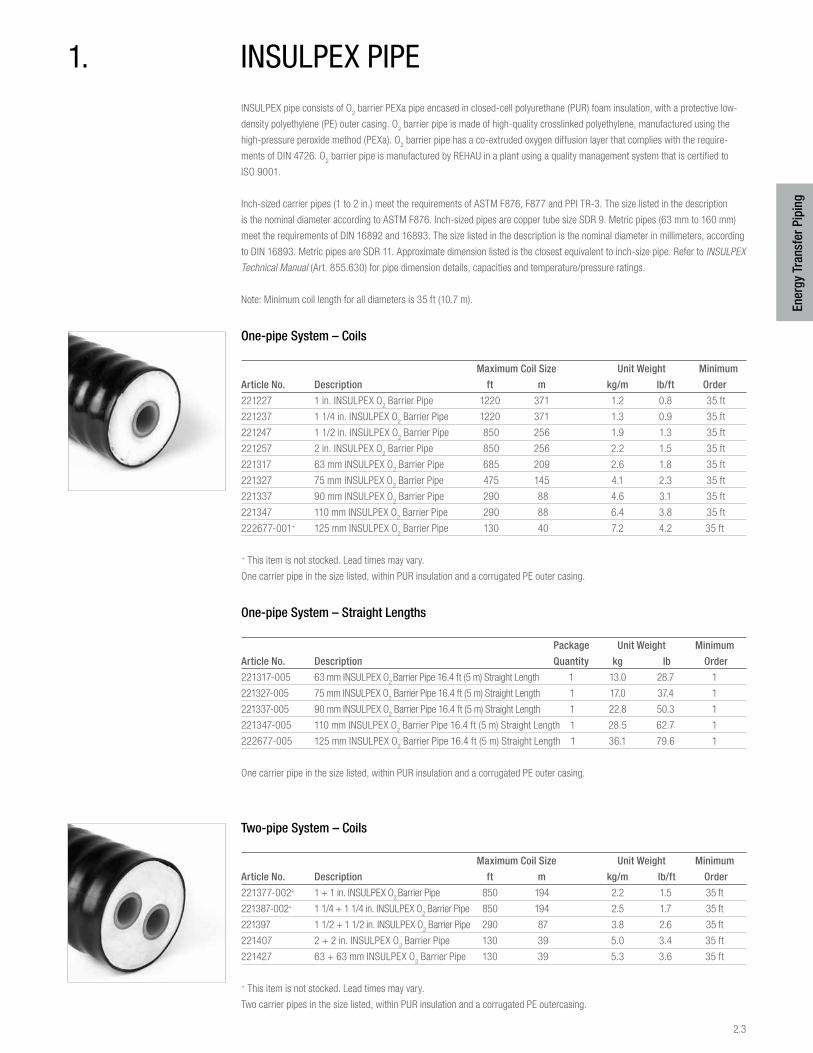
2.3
Ener
gy T
rans
fer P
ipin
g
INSULPEX pipe consists of O2 barrier PEXa pipe encased in closed-cell polyurethane (PUR) foam insulation, with a protective low-
density polyethylene (PE) outer casing. O2 barrier pipe is made of high-quality crosslinked polyethylene, manufactured using the
high-pressure peroxide method (PEXa). O2 barrier pipe has a co-extruded oxygen diffusion layer that complies with the require-
ments of DIN 4726. O2 barrier pipe is manufactured by REHAU in a plant using a quality management system that is certified to
ISO 9001.
Inch-sized carrier pipes (1 to 2 in.) meet the requirements of ASTM F876, F877 and PPI TR-3. The size listed in the description
is the nominal diameter according to ASTM F876. Inch-sized pipes are copper tube size SDR 9. Metric pipes (63 mm to 160 mm)
meet the requirements of DIN 16892 and 16893. The size listed in the description is the nominal diameter in millimeters, according
to DIN 16893. Metric pipes are SDR 11. Approximate dimension listed is the closest equivalent to inch-size pipe. Refer to INSULPEX
Technical Manual (Art. 855.630) for pipe dimension details, capacities and temperature/pressure ratings.
Note: Minimum coil length for all diameters is 35 ft (10.7 m).
One-pipe System – Coils
Maximum Coil Size Unit Weight Minimum
Article No. Description ft m kg/m lb/ft Order
221227 1 in. INSULPEX O2 Barrier Pipe 1220 371 1.2 0.8 35 ft
221237 1 1/4 in. INSULPEX O2 Barrier Pipe 1220 371 1.3 0.9 35 ft
221247 1 1/2 in. INSULPEX O2 Barrier Pipe 850 256 1.9 1.3 35 ft
221257 2 in. INSULPEX O2 Barrier Pipe 850 256 2.2 1.5 35 ft
221317 63 mm INSULPEX O2 Barrier Pipe 685 209 2.6 1.8 35 ft
221327 75 mm INSULPEX O2 Barrier Pipe 475 145 4.1 2.3 35 ft
221337 90 mm INSULPEX O2 Barrier Pipe 290 88 4.6 3.1 35 ft
221347 110 mm INSULPEX O2 Barrier Pipe 290 88 6.4 3.8 35 ft
222677-001+ 125 mm INSULPEX O2 Barrier Pipe 130 40 7.2 4.2 35 ft
+ This item is not stocked. Lead times may vary.
One carrier pipe in the size listed, within PUR insulation and a corrugated PE outer casing.
One-pipe System – Straight Lengths
Package Unit Weight Minimum
Article No. Description Quantity kg lb Order
221317-005 63 mm INSULPEX O2 Barrier Pipe 16.4 ft (5 m) Straight Length 1 13.0 28.7 1
221327-005 75 mm INSULPEX O2 Barrier Pipe 16.4 ft (5 m) Straight Length 1 17.0 37.4 1
221337-005 90 mm INSULPEX O2 Barrier Pipe 16.4 ft (5 m) Straight Length 1 22.8 50.3 1
221347-005 110 mm INSULPEX O2 Barrier Pipe 16.4 ft (5 m) Straight Length 1 28.5 62.7 1
222677-005 125 mm INSULPEX O2 Barrier Pipe 16.4 ft (5 m) Straight Length 1 36.1 79.6 1
One carrier pipe in the size listed, within PUR insulation and a corrugated PE outer casing.
Two-pipe System – Coils
Maximum Coil Size Unit Weight Minimum
Article No. Description ft m kg/m lb/ft Order
221377-002+ 1 + 1 in. INSULPEX O2 Barrier Pipe 850 194 2.2 1.5 35 ft
221387-002+ 1 1/4 + 1 1/4 in. INSULPEX O2 Barrier Pipe 850 194 2.5 1.7 35 ft
221397 1 1/2 + 1 1/2 in. INSULPEX O2 Barrier Pipe 290 87 3.8 2.6 35 ft
221407 2 + 2 in. INSULPEX O2 Barrier Pipe 130 39 5.0 3.4 35 ft
221427 63 + 63 mm INSULPEX O2 Barrier Pipe 130 39 5.3 3.6 35 ft
+ This item is not stocked. Lead times may vary.
Two carrier pipes in the size listed, within PUR insulation and a corrugated PE outercasing.
1. insulpEX pipE
2.4
Ener
gy T
rans
fer P
ipin
g
Table of Pipe Diameters
Casing RAUPEX
Outer Diameter Inside Diameter
Article No. Description in mm in mm
221227 1 in. INSULPEX O2 Barrier Pipe 3.6 91 0.88 22.2
221237 1 1/4 in. INSULPEX O2 Barrier Pipe 3.6 91 1.07 27.2
221247 1 1/2 in. INSULPEX O2 Barrier Pipe 4.4 111 1.26 32.1
221257 2 in. INSULPEX O2 Barrier Pipe 4.4 111 1.65 42.0
221317 63 mm INSULPEX O2 Barrier Pipe 5.0 126 2.04 51.7
221327 75 mm INSULPEX O2 Barrier Pipe 5.6 142 2.43 61.8
221337 90 mm INSULPEX O2 Barrier Pipe 6.4 162 2.92 74.1
221347 110 mm INSULPEX O2 Barrier Pipe 6.4 162 3.56 90.5
222677-001 125 mm INSULPEX O2 Barrier Pipe 7.2 182 4.05 102.8
221377-002 1 + 1 in. INSULPEX O2 Barrier Pipe 4.4 111 0.88 22.2
221387-002 1 1/4 + 1 1/4 in. INSULPEX O2 Barrier Pipe 4.4 111 1.07 27.2
221397 1 1/2 + 1 1/2 in. INSULPEX O2 Barrier Pipe 6.4 162 1.26 32.1
221407 2 + 2 in. INSULPEX O2 Barrier Pipe 7.2 182 1.65 42.0
221427 63 + 63 mm INSULPEX O2 Barrier Pipe 7.2 182 2.04 51.7
Casing OD is the average outside diameter between the higher and the lower rib profiles.

2.5
Ener
gy T
rans
fer P
ipin
g
2. insulpEX End capsREHAU’s installation accessories are designed to save time and enhance craftsmanship.
Heat Shrink End Cap, One-pipe System
Package Unit Weight Minimum
Article No. Description Quantity kg lb Order
240263 1 in. INSULPEX Heat Shrink End Cap 1 0.10 0.22 1
240273 1 1/4 in. INSULPEX Heat Shrink End Cap 1 0.11 0.24 1
240273 1 1/2 in. INSULPEX Heat Shrink End Cap 1 0.11 0.24 1
240323 2 in. INSULPEX Heat Shrink End Cap 1 0.12 0.26 1
240323 63 mm INSULPEX Heat Shrink End Cap 1 0.15 0.33 1
240323 75 mm INSULPEX Heat Shrink End Cap 1 0.12 0.26 1
240283 90 mm INSULPEX Heat Shrink End Cap 1 0.14 0.31 1
240293 110/125 mm INSULPEX Heat Shrink End Cap 1 0.20 0.43 1
Heat Shrink End Cap, Two-pipe System
Package Unit Weight Minimum
Article No. Description Quantity kg lb Order
240333 1 + 1 in. INSULPEX Heat Shrink End Cap 1 0.11 0.24 1
240333 1 1/4 + 1 1/4 in. INSULPEX Heat Shrink End Cap 1 0.15 0.34 1
240343 1 1/2 + 1 1/2 in. INSULPEX Heat Shrink End Cap 1 0.15 0.34 1
239061 2 + 2 in./63 + 63 mm INSULPEX End Cap* 1 0.21 0.45 1
* Rubber cap, not shrinking.
Heat shrink end caps provide a watertight seal around the end of INSULPEX, sealing onto RAUPEX pipe and the PE casing to
protect against water infiltration in buried applications. Heat shrink end caps include sandpaper for "roughing" surfaces of pipes.
Follow installation instructions in the INSULPEX Installation Guide (855.631).
Slip-on End Cap, One-pipe System
Package Unit Weight Minimum
Article No. Description Quantity kg lb Order
246989+ 1 in. INSULPEX Slip-on End Cap 1 0.02 0.05 1
246989+ 1 1/4 in. INSULPEX Slip-on End Cap 1 0.11 0.24 1
242604 1 1/2 in. INSULPEX Slip-on End Cap 1 0.04 0.08 1
242604 2 in. INSULPEX Slip-on End Cap 1 0.04 0.08 1
242624 63 mm INSULPEX Slip-on End Cap 1 0.12 0.26 1
242644 75 mm INSULPEX Slip-on End Cap 1 0.04 0.09 1
242664 90 mm INSULPEX Slip-on End Cap 1 0.05 0.11 1
242674 110 mm INSULPEX Slip-on End Cap 1 0.05 0.10 1
288374-001+ 125 mm INSULPEX Slip-on End Cap 1 0.50 1.10 1
+ This item is not stocked. Lead times may vary.
2.6
Ener
gy T
rans
fer P
ipin
g
Slip-on End Cap, Two-pipe System
Package Unit Weight Minimum
Article No. Description Quantity kg lb Order
242724 1 + 1 in. INSULPEX Slip-on End Cap 1 0.04 0.08 1
242724 1 1/4 + 1 1/4 in. INSULPEX Slip-on End Cap 1 0.04 0.08 1
242784 1 1/2 + 1 1/2 in. INSULPEX Slip-on End Cap 1 0.05 0.12 1
239091 2 + 2 in./ 63 + 63 mm INSULPEX Slip-on End Cap 1 0.07 0.16 1
Slip-on end caps improve cosmetic appearance at ends of INSULPEX pipes inside a building or chamber. Slip-on end caps are not
watertight, and are not certified for underground burial.
Wall Sealing Rings
Package Unit Weight Minimum
Article No. Description Quantity kg lb Order
240363 91 mm ID Wall Sealing Ring (5.25 in. OD) 1 0.45 1.0 1
240373 111 mm ID Wall Sealing Ring (6.00 in. OD) 1 0.30 0.7 1
240383 126 mm ID Wall Sealing Ring (6.60 in. OD) 1 0.50 1.1 1
240393 142 mm ID Wall Sealing Ring (7.20 in. OD) 1 0.60 1.32 1
240403 162 mm ID Wall Sealing Ring (8.00 in. OD) 1 0.35 0.77 1
239101 182 mm ID Wall Sealing Ring (8.60 in. OD) 1 0.50 1.10 1
Neoprene wall sealing rings fit tightly over the INSULPEX casing, and are meant to be located at wall penetrations. Barbed design
prevents pull out. Use the sizing chart in the INSULPEX Technical Manual (855.630) or from the pipe diameters chart located on
page 2, to determine the correct wall sealing ring.
2.7
Ener
gy T
rans
fer P
ipin
g
Universal tee insulation kits are molded from polyethylene, with staggered ends that can be cut for use with various pipe diameters.
Insulation is NOT included with these kits. Follow directions included with kit. Small universal insulation kit is for pipes with casing
OD up to 126 mm. Large Universal Tee Insulation Kit is for pipes with casing OD up to 182 mm.
Universal Straight Coupling Insulation Kits – Generation I
Package Unit Weight Minimum
Article No. Description Quantity kg lb Order
243828 Small Universal Coupling Insulation Kit,
for up to 142 mm OD INSULPEX pipe 1 3.5 7.7 1
243838 Large Universal Coupling Insulation Kit,
for up to 182 mm OD INSULPEX pipe 1 1.7 3.8 1
Kits include two heat shrink sleeves for sealing around INSULPEX pipes.
Small Universal Straight Coupling Insulation Kit – Generation II
Package Unit Weight Minimum
Article No. Description Quantity kg lb Order
351067-001 Small Universal Straight Coupling Insulation Kit,
for up to 126 mm OD INSULPEX pipe 1 2.1 4.6 1
Order small diameter sealing rings separately per the outer diameter of the INSULPEX pipe.
Small Universal Elbow Insulation Kits – Generation II
Package Unit Weight Minimum
Article No. Description Quantity kg lb Order
351068-001 Small Universal Elbow Coupling Insulation Kit,
for up to 126 mm OD INSULPEX pipe 1 2.1 4.6 1
Order small diameter sealing rings separately per the outer diameter of the INSULPEX pipe.
Small Universal Tee Insulation Kit – Generation II
Package Unit Weight Minimum
Article No. Description Quantity kg lb Order
297932-001 Small Universal Tee Insulation Kit,
for up to 126 mm OD INSULPEX pipe 1 1.90 4.2 1
176282-050 Small Tee Shell Kit Plug (111 mm SR) 1 0.10 0.2 1
Order small diameter sealing rings separately per the outer diameter of the INSULPEX pipe.
3. insulpEX insulaTion KiTs
2.8
Ener
gy T
rans
fer P
ipin
g
Small INSULPEX Sealing Rings, Small Diameter – Generation II
Package Unit Weight Minimum
Article No. Description Quantity kg lb Order
297924-001 Small Insulation Kit Sealing Ring 91 mm 1 0.30 0.7 1
297927-001 Small Insulation Kit Sealing Ring 111 mm 1 0.20 0.4 1
297930-001 Small Insulation Kit Sealing Ring 126 mm 1 0.11 0.2 1
Order small diameter sealing rings separately per the outer diameter of the INSULPEX pipe.
Large Universal Straight Coupling Insulation Kit – Generation II
Package Unit Weight Minimum
Article No. Description Quantity kg lb Order
352038-001 Large Universal Straight Coupling Insulation Kit,
for up to 182 mm OD INSULPEX pipe 1 5.2 11.5 1
Order large diameter sealing rings separately per the outer diameter of the INSULPEX pipe.
Large Universal Elbow Insulation Kits – Generation II
Package Unit Weight Minimum
Article No. Description Quantity kg lb Order
352039-001 Large Universal Elbow Coupling Insulation Kit,
for up to 182 mm OD INSULPEX pipe 1 4.4 9.7 1
Order large diameter sealing rings separately per the outer diameter of the INSULPEX pipe.
Large Universal Tee Insulation Kit – Generation II
Package Unit Weight Minimum
Article No. Description Quantity kg lb Order
351054-001 Large Universal Tee Insulation Kit,
for up to 182 mm OD INSULPEX pipe 1 3.60 7.9 1
176302-050 Large Tee Shell Kit Plug (162 mm SR) 1 0.27 0.6 1
Order large diameter sealing rings separately per the outer diameter of the INSULPEX pipe.
Large INSULPEX Sealing Rings, Large Diameter – Generation II
Package Unit Weight Minimum
Article No. Description Quantity kg lb Order
351056-001 Large Insulation Kit Sealing Ring 91 mm 1 1.08 2.38 1
351057-001 Large Insulation Kit Sealing Ring 111 mm 1 1.03 2.26 1
351058-001 Large Insulation Kit Sealing Ring 126 mm 1 0.95 2.09 1
351059-001 Large Insulation Kit Sealing Ring 142 mm 1 0.90 1.98 1
351061-001 Large Insulation Kit Sealing Ring 162 mm 1 0.85 1.88 1
351062-001 Large Insulation Kit Sealing Ring 182 mm 1 0.68 1.49 1
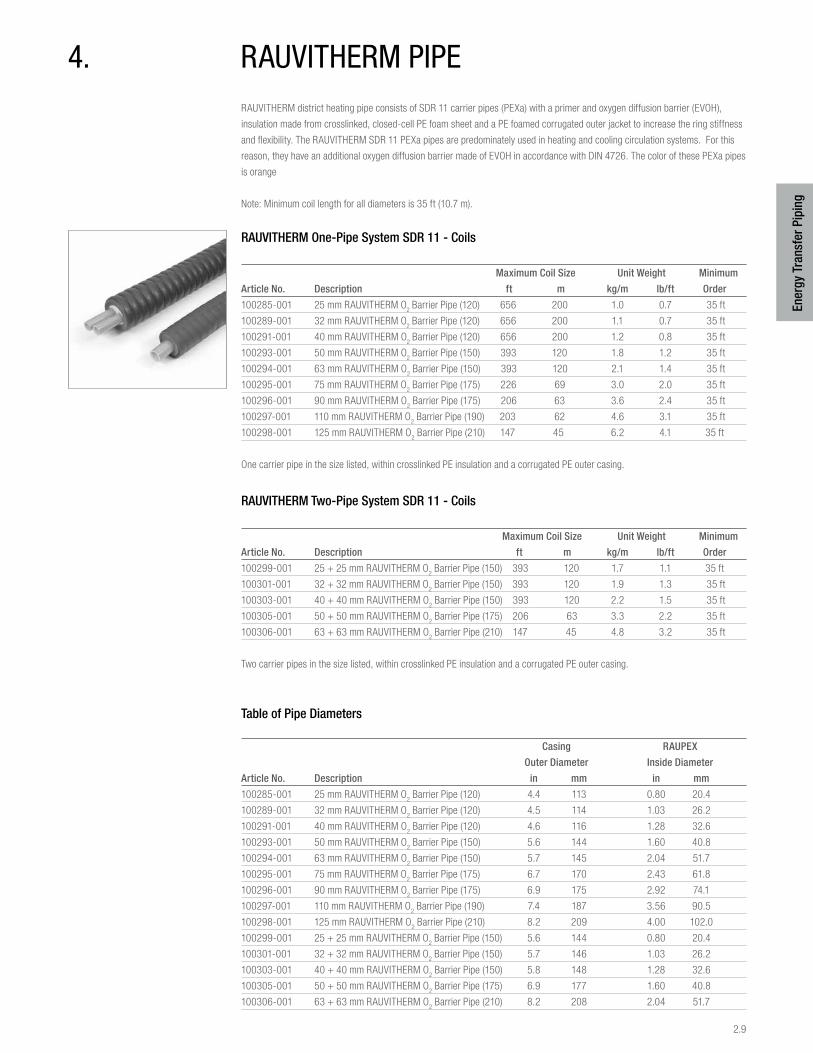
2.9
Ener
gy T
rans
fer P
ipin
g
4. rauviTHErM pipERAUVITHERM district heating pipe consists of SDR 11 carrier pipes (PEXa) with a primer and oxygen diffusion barrier (EVOH),
insulation made from crosslinked, closed-cell PE foam sheet and a PE foamed corrugated outer jacket to increase the ring stiffness
and flexibility. The RAUVITHERM SDR 11 PEXa pipes are predominately used in heating and cooling circulation systems. For this
reason, they have an additional oxygen diffusion barrier made of EVOH in accordance with DIN 4726. The color of these PEXa pipes
is orange
Note: Minimum coil length for all diameters is 35 ft (10.7 m).
RAUVITHERM One-Pipe System SDR 11 - Coils
Maximum Coil Size Unit Weight Minimum
Article No. Description ft m kg/m lb/ft Order
100285-001 25 mm RAUVITHERM O2 Barrier Pipe (120) 656 200 1.0 0.7 35 ft
100289-001 32 mm RAUVITHERM O2 Barrier Pipe (120) 656 200 1.1 0.7 35 ft
100291-001 40 mm RAUVITHERM O2 Barrier Pipe (120) 656 200 1.2 0.8 35 ft
100293-001 50 mm RAUVITHERM O2 Barrier Pipe (150) 393 120 1.8 1.2 35 ft
100294-001 63 mm RAUVITHERM O2 Barrier Pipe (150) 393 120 2.1 1.4 35 ft
100295-001 75 mm RAUVITHERM O2 Barrier Pipe (175) 226 69 3.0 2.0 35 ft
100296-001 90 mm RAUVITHERM O2 Barrier Pipe (175) 206 63 3.6 2.4 35 ft
100297-001 110 mm RAUVITHERM O2 Barrier Pipe (190) 203 62 4.6 3.1 35 ft
100298-001 125 mm RAUVITHERM O2 Barrier Pipe (210) 147 45 6.2 4.1 35 ft
One carrier pipe in the size listed, within crosslinked PE insulation and a corrugated PE outer casing.
RAUVITHERM Two-Pipe System SDR 11 - Coils
Maximum Coil Size Unit Weight Minimum
Article No. Description ft m kg/m lb/ft Order
100299-001 25 + 25 mm RAUVITHERM O2 Barrier Pipe (150) 393 120 1.7 1.1 35 ft
100301-001 32 + 32 mm RAUVITHERM O2 Barrier Pipe (150) 393 120 1.9 1.3 35 ft
100303-001 40 + 40 mm RAUVITHERM O2 Barrier Pipe (150) 393 120 2.2 1.5 35 ft
100305-001 50 + 50 mm RAUVITHERM O2 Barrier Pipe (175) 206 63 3.3 2.2 35 ft
100306-001 63 + 63 mm RAUVITHERM O2 Barrier Pipe (210) 147 45 4.8 3.2 35 ft
Two carrier pipes in the size listed, within crosslinked PE insulation and a corrugated PE outer casing.
Table of Pipe Diameters
Casing RAUPEX
Outer Diameter Inside Diameter
Article No. Description in mm in mm
100285-001 25 mm RAUVITHERM O2 Barrier Pipe (120) 4.4 113 0.80 20.4
100289-001 32 mm RAUVITHERM O2 Barrier Pipe (120) 4.5 114 1.03 26.2
100291-001 40 mm RAUVITHERM O2 Barrier Pipe (120) 4.6 116 1.28 32.6
100293-001 50 mm RAUVITHERM O2 Barrier Pipe (150) 5.6 144 1.60 40.8
100294-001 63 mm RAUVITHERM O2 Barrier Pipe (150) 5.7 145 2.04 51.7
100295-001 75 mm RAUVITHERM O2 Barrier Pipe (175) 6.7 170 2.43 61.8
100296-001 90 mm RAUVITHERM O2 Barrier Pipe (175) 6.9 175 2.92 74.1
100297-001 110 mm RAUVITHERM O2 Barrier Pipe (190) 7.4 187 3.56 90.5
100298-001 125 mm RAUVITHERM O2 Barrier Pipe (210) 8.2 209 4.00 102.0
100299-001 25 + 25 mm RAUVITHERM O2 Barrier Pipe (150) 5.6 144 0.80 20.4
100301-001 32 + 32 mm RAUVITHERM O2 Barrier Pipe (150) 5.7 146 1.03 26.2
100303-001 40 + 40 mm RAUVITHERM O2 Barrier Pipe (150) 5.8 148 1.28 32.6
100305-001 50 + 50 mm RAUVITHERM O2 Barrier Pipe (175) 6.9 177 1.60 40.8
100306-001 63 + 63 mm RAUVITHERM O2 Barrier Pipe (210) 8.2 208 2.04 51.7
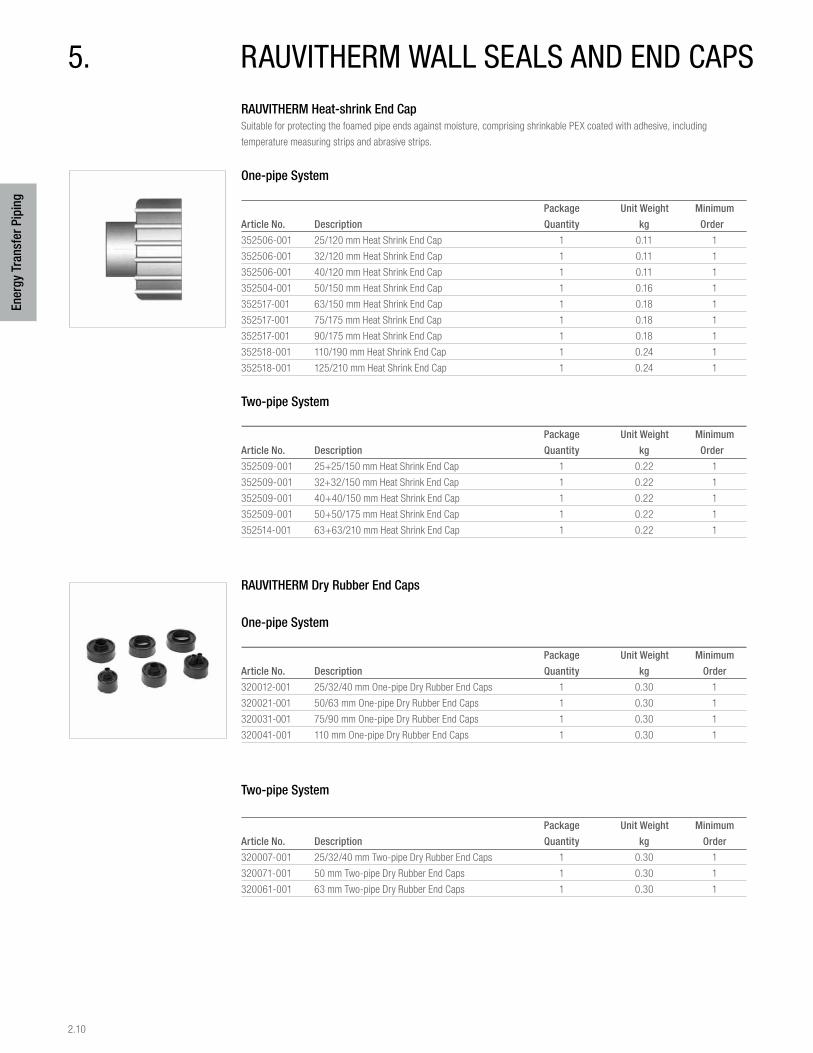
2.10
Ener
gy T
rans
fer P
ipin
g
5. rauviTHErM wall sEals and End capsRAUVITHERM Heat-shrink End Cap Suitable for protecting the foamed pipe ends against moisture, comprising shrinkable PEX coated with adhesive, including
temperature measuring strips and abrasive strips.
One-pipe System
Package Unit Weight Minimum
Article No. Description Quantity kg Order
352506-001 25/120 mm Heat Shrink End Cap 1 0.11 1
352506-001 32/120 mm Heat Shrink End Cap 1 0.11 1
352506-001 40/120 mm Heat Shrink End Cap 1 0.11 1
352504-001 50/150 mm Heat Shrink End Cap 1 0.16 1
352517-001 63/150 mm Heat Shrink End Cap 1 0.18 1
352517-001 75/175 mm Heat Shrink End Cap 1 0.18 1
352517-001 90/175 mm Heat Shrink End Cap 1 0.18 1
352518-001 110/190 mm Heat Shrink End Cap 1 0.24 1
352518-001 125/210 mm Heat Shrink End Cap 1 0.24 1
Two-pipe System
Package Unit Weight Minimum
Article No. Description Quantity kg Order
352509-001 25+25/150 mm Heat Shrink End Cap 1 0.22 1
352509-001 32+32/150 mm Heat Shrink End Cap 1 0.22 1
352509-001 40+40/150 mm Heat Shrink End Cap 1 0.22 1
352509-001 50+50/175 mm Heat Shrink End Cap 1 0.22 1
352514-001 63+63/210 mm Heat Shrink End Cap 1 0.22 1
RAUVITHERM Dry Rubber End Caps
One-pipe System
Package Unit Weight Minimum
Article No. Description Quantity kg Order
320012-001 25/32/40 mm One-pipe Dry Rubber End Caps 1 0.30 1
320021-001 50/63 mm One-pipe Dry Rubber End Caps 1 0.30 1
320031-001 75/90 mm One-pipe Dry Rubber End Caps 1 0.30 1
320041-001 110 mm One-pipe Dry Rubber End Caps 1 0.30 1
Two-pipe System
Package Unit Weight Minimum
Article No. Description Quantity kg Order
320007-001 25/32/40 mm Two-pipe Dry Rubber End Caps 1 0.30 1
320071-001 50 mm Two-pipe Dry Rubber End Caps 1 0.30 1
320061-001 63 mm Two-pipe Dry Rubber End Caps 1 0.30 1
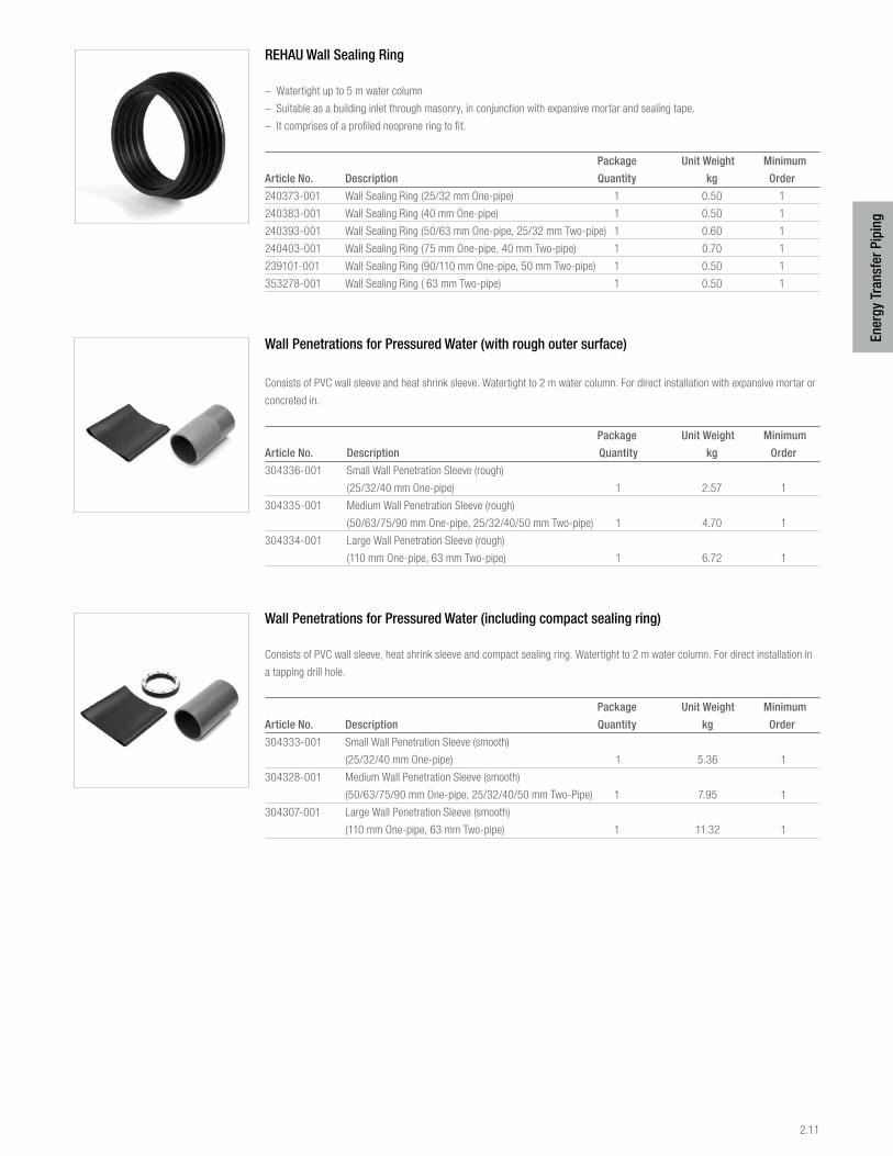
2.11
Ener
gy T
rans
fer P
ipin
g
REHAU Wall Sealing Ring
– Watertight up to 5 m water column
– Suitable as a building inlet through masonry, in conjunction with expansive mortar and sealing tape.
– It comprises of a profiled neoprene ring to fit.
Package Unit Weight Minimum
Article No. Description Quantity kg Order
240373-001 Wall Sealing Ring (25/32 mm One-pipe) 1 0.50 1
240383-001 Wall Sealing Ring (40 mm One-pipe) 1 0.50 1
240393-001 Wall Sealing Ring (50/63 mm One-pipe, 25/32 mm Two-pipe) 1 0.60 1
240403-001 Wall Sealing Ring (75 mm One-pipe, 40 mm Two-pipe) 1 0.70 1
239101-001 Wall Sealing Ring (90/110 mm One-pipe, 50 mm Two-pipe) 1 0.50 1
353278-001 Wall Sealing Ring ( 63 mm Two-pipe) 1 0.50 1
Wall Penetrations for Pressured Water (with rough outer surface)
Consists of PVC wall sleeve and heat shrink sleeve. Watertight to 2 m water column. For direct installation with expansive mortar or
concreted in.
Package Unit Weight Minimum
Article No. Description Quantity kg Order
304336-001 Small Wall Penetration Sleeve (rough)
(25/32/40 mm One-pipe) 1 2.57 1
304335-001 Medium Wall Penetration Sleeve (rough)
(50/63/75/90 mm One-pipe, 25/32/40/50 mm Two-pipe) 1 4.70 1
304334-001 Large Wall Penetration Sleeve (rough)
(110 mm One-pipe, 63 mm Two-pipe) 1 6.72 1
Wall Penetrations for Pressured Water (including compact sealing ring)
Consists of PVC wall sleeve, heat shrink sleeve and compact sealing ring. Watertight to 2 m water column. For direct installation in
a tapping drill hole.
Package Unit Weight Minimum
Article No. Description Quantity kg Order
304333-001 Small Wall Penetration Sleeve (smooth)
(25/32/40 mm One-pipe) 1 5.36 1
304328-001 Medium Wall Penetration Sleeve (smooth)
(50/63/75/90 mm One-pipe, 25/32/40/50 mm Two-Pipe) 1 7.95 1
304307-001 Large Wall Penetration Sleeve (smooth)
(110 mm One-pipe, 63 mm Two-pipe) 1 11.32 1
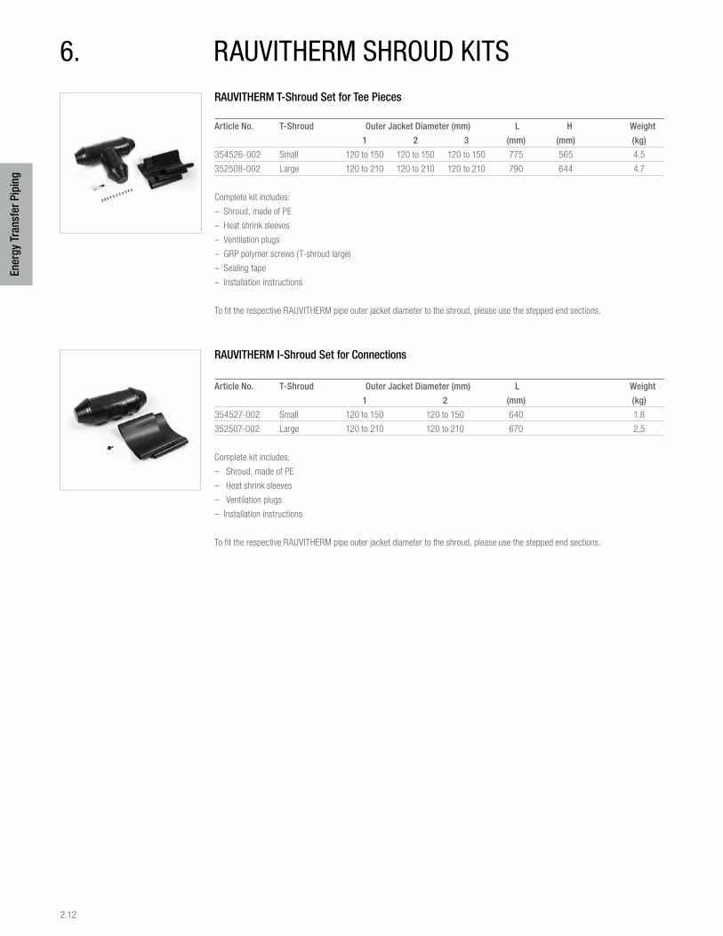
2.12
Ener
gy T
rans
fer P
ipin
g
6. rauviTHErM sHroud KiTsRAUVITHERM T-Shroud Set for Tee Pieces
Article No. T-Shroud Outer Jacket Diameter (mm) L H Weight
1 2 3 (mm) (mm) (kg)
354526-002 Small 120 to 150 120 to 150 120 to 150 775 565 4.5
352508-002 Large 120 to 210 120 to 210 120 to 210 790 644 4.7
Complete kit includes:
– Shroud, made of PE
– Heat shrink sleeves
– Ventilation plugs
– GRP polymer screws (T-shroud large)
– Sealing tape
– Installation instructions
To fit the respective RAUVITHERM pipe outer jacket diameter to the shroud, please use the stepped end sections.
RAUVITHERM I-Shroud Set for Connections
Article No. T-Shroud Outer Jacket Diameter (mm) L Weight
1 2 (mm) (kg)
354527-002 Small 120 to 150 120 to 150 640 1.8
352507-002 Large 120 to 210 120 to 210 670 2.5
Complete kit includes:
– Shroud, made of PE
– Heat shrink sleeves
– Ventilation plugs
– Installation instructions
To fit the respective RAUVITHERM pipe outer jacket diameter to the shroud, please use the stepped end sections.
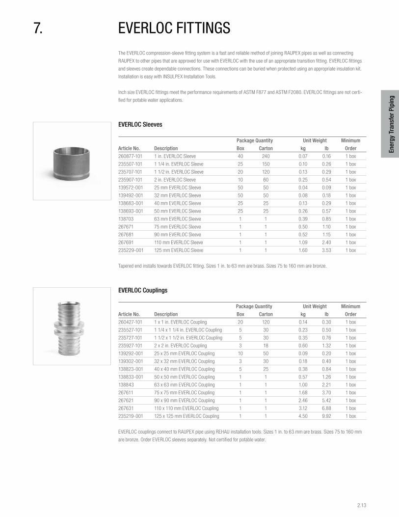
2.13
Ener
gy T
rans
fer P
ipin
g
7. EvErloc fiTTingsThe EVERLOC compression-sleeve fitting system is a fast and reliable method of joining RAUPEX pipes as well as connecting
RAUPEX to other pipes that are approved for use with EVERLOC with the use of an appropriate transition fitting. EVERLOC fittings
and sleeves create dependable connections. These connections can be buried when protected using an appropriate insulation kit.
Installation is easy with INSULPEX Installation Tools.
Inch size EVERLOC fittings meet the performance requirements of ASTM F877 and ASTM F2080. EVERLOC fittings are not certi-
fied for potable water applications.
EVERLOC Sleeves
Package Quantity Unit Weight Minimum
Article No. Description Box Carton kg lb Order
260877-101 1 in. EVERLOC Sleeve 40 240 0.07 0.16 1 box
235507-101 1 1/4 in. EVERLOC Sleeve 25 150 0.10 0.26 1 box
235707-101 1 1/2 in. EVERLOC Sleeve 20 120 0.13 0.29 1 box
235907-101 2 in. EVERLOC Sleeve 10 60 0.25 0.54 1 box
139572-001 25 mm EVERLOC Sleeve 50 50 0.04 0.09 1 box
139492-001 32 mm EVERLOC Sleeve 50 50 0.08 0.18 1 box
138683-001 40 mm EVERLOC Sleeve 25 25 0.13 0.29 1 box
138693-001 50 mm EVERLOC Sleeve 25 25 0.26 0.57 1 box
138703 63 mm EVERLOC Sleeve 1 1 0.39 0.85 1 box
267671 75 mm EVERLOC Sleeve 1 1 0.50 1.10 1 box
267681 90 mm EVERLOC Sleeve 1 1 0.52 1.15 1 box
267691 110 mm EVERLOC Sleeve 1 1 1.09 2.40 1 box
235229-001 125 mm EVERLOC Sleeve 1 1 1.60 3.53 1 box
Tapered end installs towards EVERLOC fitting. Sizes 1 in. to 63 mm are brass. Sizes 75 to 160 mm are bronze.
EVERLOC Couplings
Package Quantity Unit Weight Minimum
Article No. Description Box Carton kg lb Order
260427-101 1 x 1 in. EVERLOC Coupling 20 120 0.14 0.30 1 box
235527-101 1 1/4 x 1 1/4 in. EVERLOC Coupling 5 30 0.23 0.50 1 box
235727-101 1 1/2 x 1 1/2 in. EVERLOC Coupling 5 30 0.35 0.76 1 box
235927-101 2 x 2 in. EVERLOC Coupling 3 18 0.60 1.32 1 box
139292-001 25 x 25 mm EVERLOC Coupling 10 50 0.09 0.20 1 box
139302-001 32 x 32 mm EVERLOC Coupling 3 30 0.18 0.40 1 box
138823-001 40 x 40 mm EVERLOC Coupling 5 25 0.38 0.84 1 box
138833-001 50 x 50 mm EVERLOC Coupling 1 1 0.57 1.26 1 box
138843 63 x 63 mm EVERLOC Coupling 1 1 1.00 2.21 1 box
267611 75 x 75 mm EVERLOC Coupling 1 1 1.68 3.70 1 box
267621 90 x 90 mm EVERLOC Coupling 1 1 2.46 5.42 1 box
267631 110 x 110 mm EVERLOC Coupling 1 1 3.12 6.88 1 box
235219-001 125 x 125 mm EVERLOC Coupling 1 1 4.50 9.92 1 box
EVERLOC couplings connect to RAUPEX pipe using REHAU installation tools. Sizes 1 in. to 63 mm are brass. Sizes 75 to 160 mm
are bronze. Order EVERLOC sleeves separately. Not certified for potable water.
2.14
Ener
gy T
rans
fer P
ipin
g
EVERLOC Reducer Couplings
Package Quantity Unit Weight Minimum
Article No. Description Box Carton kg lb Order
235517-101 1 1/4 x 1 in. EVERLOC Coupling 10 60 0.20 0.43 1 box
235717-101 1 1/2 x 1 1/4 in. EVERLOC Coupling 5 30 0.30 0.66 1 box
235737-101 1 1/2 x 1 in. EVERLOC Coupling 5 30 0.27 0.61 1 box
235917-101 2 x 1 1/2 in. EVERLOC Coupling 3 18 0.50 1.11 1 box
235937-101 2 x 1 1/4 in. EVERLOC Coupling 3 18 0.60 1.31 1 box
235947-101 2 x 1 in. EVERLOC Coupling 3 18 0.44 0.97 1 box
139342-001+ 32 x 25 mm EVERLOC Coupling 3 30 0.14 0.31 1 box
138853-001+ 40 x 32 mm EVERLOC Coupling 5 25 0.28 0.62 1 box
138863-001+ 50 x 40 mm EVERLOC Coupling 1 1 0.48 1.06 1 box
138873-001+ 63 x 50 mm EVERLOC Coupling 1 1 0.76 1.67 1 box
222217+ 63 mm x 2 in. EVERLOC Coupling 1 1 1.00 2.20 1 box
267641+ 75 x 63 mm EVERLOC Coupling 1 1 1.40 3.10 1 box
267651+ 90 x 75 mm EVERLOC Coupling 1 1 2.70 4.56 1 box
267661+ 110 x 90 mm EVERLOC Coupling 1 1 3.10 6.80 1 box
+ This item is not stocked. Lead times may vary.
EVERLOC couplings connect to RAUPEX pipe using REHAU installation tools. Sizes 1 in. to 63 mm are brass. Sizes 75 to 160 mm
are bronze. Order EVERLOC sleeves separately.
EVERLOC Dual Adapters
Package Quantity Unit Weight Minimum
Article No. Description Box Carton kg lb Order
260417-101 1 in. EVERLOC x 1 in. C Male
(Street ) or 3/4 in. C Female (Sweat) 25 150 0.14 0.30 1 box
260947-101 1 in. EVERLOC x 1 1/4 in. C Male
(Street) or 1 in. C Female (Sweat) 20 120 0.16 0.36 1 box
235567-101 1 1/4 in. EVERLOC x 1 1/4 in. C Male
(Street)or 1 in. C Female (Sweat) 5 30 0.22 0.49 1 box
235577-101 1 1/4 in. EVERLOC x 1 1/2 in. C Male
(Street) or 1 1/4 in. C Female (Sweat) 5 30 0.25 0.55 1 box
235767-101 1 1/2 in. EVERLOC x 1 1/2 in. C Male
(Street) or 1 1/4 in. C Female (Sweat) 5 30 0.32 0.71 1 box
235777-101 1 1/2 in. EVERLOC x 2 in. C Male
(Street) or 1 1/2 in. C Female (Sweat) 5 30 .051 1.12 1 box
235967-101 2 in. EVERLOC x 2 in. C Male
(Street) or 1 1/2 in. C Female (Sweat) 5 30 0.64 1.42 1 box
235977-101 2 in. EVERLOC x 2 1/2 in. C Male
(Street) or 2 in. C Female (Sweat) 3 18 0.80 1.76 1 box
Adapter fittings connect to RAUPEX pipe. Sizes 1 in. to 63 mm are brass. All of these adapters can be used as male (street) or
female (sweat) fittings. Make solder connection before connecting to RAUPEX pipe. Fittings install using REHAU installation tools.
Order EVERLOC sleeves separately.
2.15
Ener
gy T
rans
fer P
ipin
g
EVERLOC MPT Adapters
Package Quantity Unit Weight Minimum
Article No. Description Box Carton kg lb Order
260437-101 1 in. EVERLOC x 1 in. MPT
or 3/4 in. C Female 15 90 0.19 0.43 1 box
730053-001 1 1/4 in. EVERLOC x 1 in. MPT
or 3/4 in. C Female 5 30 0.19 0.41 1 box
235557-101 1 1/4 in. EVERLOC x 1 1/4 in. MPT
or 1 in. C Female 5 30 0.33 0.73 1 box
235757-101 1 1/2 in. EVERLOC x 1 1/2 in. MPT
or 1 1/4 in. C Female 5 30 0.51 1.11 1 box
235957-101 2 in. EVERLOC x 2 in. MPT
or 1 1/2 in. C Female 3 18 0.89 1.96 1 box
298246-001 25 mm EVERLOC x 1 in. MPT
or 3/4 in. C Female 15 90 0.18 0.40 1 box
235117-001 32 mm EVERLOC x 1 1/4 in. MPT
or 1 in. C Female 15 90 0.34 0.75 1 box
235127-001 40 mm EVERLOC x 1 1/2 in. MPT
or 1 1/4 C Female 1 1 0.50 1.10 1 box
235137-001 50 mm EVERLOC x 2 in. MPT
or 1 1/2 C Female 1 1 0.84 1.85 1 box
235157 63 mm EVERLOC x 2 1/2 in. MPT
or 2 in. C Female 1 1 1.51 3.33 1 box
235147 63 mm EVERLOC x 2 in. MPT Adapter 1 1 1.50 3.30 1 box
235167 75 mm EVERLOC x 3 in. MPT Adapter 1 1 2.33 5.14 1 box
235177 90 mm EVERLOC x 3 in. MPT Adapter 1 1 2.10 4.62 1 box
235187 110 mm EVERLOC x 4 in. MPT Adapter 1 1 3.69 8.14 1 box
Adapter fittings connect to RAUPEX pipe. Make threaded or solder connections before connecting to RAUPEX pipe. Order EVERLOC
sleeves separately. Sizes up to 63 mm are brass. Sizes 75 to 110 mm are bronze. Make threaded connection before connecting to
RAUPEX pipe. Fittings are installed using REHAU installation tools. Order EVERLOC sleeves separately.
EVERLOC Plugs
Package Quantity Unit Weight Minimum
Article No. Description Box Carton kg lb Order
260497-101 1 in. EVERLOC Plug 30 180 0.09 0.20 1 box
235267-101 1 1/4 EVERLOC Plug 20 120 0.10 0.22 1 box
Order EVERLOC sleeves separately.
EVERLOC 90° Elbows
Package Quantity Unit Weight Minimum
Article No. Description Box Carton kg lb Order
260717-101 1 x 1 in. EVERLOC Elbow 10 60 0.25 0.56 1 box
235597-101 1 1/4 x 1 1/4 in. EVERLOC Elbow 8 48 0.37 0.82 1 box
235797-101 1 1/2 x 1 1/2 in. EVERLOC Elbow 2 12 0.64 1.47 1 box
235997-101 2 x 2 in. EVERLOC Elbow 2 12 1.08 2.38 1 box
139522-001 25 x 25 mm EVERLOC Elbow 10 50 0.16 0.35 1 box
139532-001 32 x 32 mm EVERLOC Elbow 3 30 0.29 0.64 1 box
138923-001 40 x 40 mm EVERLOC Elbow 1 1 0.52 1.15 1 box
138933-001 50 x 50 mm EVERLOC Elbow 1 1 0.82 1.81 1 box
138943 63 x 63 mm EVERLOC Elbow 1 1 1.67 3.69 1 box
267751 75 x 75 mm EVERLOC Elbow 1 1 2.44 5.38 1 box
267761 90 x 90 mm EVERLOC Elbow 1 1 3.30 7.28 1 box
267771 110 x 110 mm EVERLOC Elbow 1 1 5.32 11.7 1 box
EVERLOC elbows connect to RAUPEX pipe using REHAU installation tools. Sizes up to 63 mm are brass. Sizes 75 to 110 mm are
bronze. Order EVERLOC sleeves separately.
2.16
Ener
gy T
rans
fer P
ipin
g
EVERLOC Straight Tees
Package Quantity Unit Weight Minimum
Article No. Description Box Carton kg lb Order
260977-101 1 x 1 x 1 in. EVERLOC Tee 8 48 0.34 0.77 1 box
235607-101 1 1/4 x 1 1/4 x 1 1/4 in. EVERLOC Tee 5 30 0.51 1.12 1 box
235807-101 1 1/2 x 1 1/2 x 1 1/2 in. EVERLOC Tee 2 12 0.87 1.93 1 box
236007-101 2 x 2 x 2 in. EVERLOC Tee 1 6 1.39 3.08 1 box
139122-001 25 x 25 x 25 mm EVERLOC Tee 10 50 0.20 0.44 1 box
139132-001 32 x 32 x 32 mm EVERLOC Tee 3 30 0.40 0.88 1 box
138773-001 40 x 40 x 40 mm EVERLOC Tee 1 1 0.77 1.70 1 box
244372-001 50 x 50 x 50 mm EVERLOC Tee 1 1 0.87 1.92 1 box
244382 63 x 63 x 63 mm EVERLOC Tee 1 1 2.14 4.72 1 box
221946-001 75 x 75 x 75 mm EVERLOC Tee 1 1 3.47 7.65 1 box
221948-001 90 x 90 x 90 mm EVERLOC Tee 1 1 4.00 8.00 1 box
221953-001 110 x 110 x 110 mm EVERLOC Tee 1 1 7.09 15.6 1 box
These fittings connect to RAUPEX pipe using REHAU installation tools. Order EVERLOC sleeves separately.
EVERLOC Branch Reducing Tees
Package Quantity Unit Weight Minimum
Article No. Description Box Carton kg lb Order
235617-101 1 1/4 x 1 1/4 x 1 in. EVERLOC Tee 5 30 0.45 1.00 1 box
235627-101 1 1/4 x 1 1/4 x 3/4 in. EVERLOC Tee 5 30 0.40 0.89 1 box
235817-101 1 1/2 x 1 1/2 x 1 1/4 in. EVERLOC Tee 2 12 0.65 1.43 1 box
235827-101 1 1/2 x 1 1/2 x 1 in. EVERLOC Tee 2 12 0.69 1.53 1 box
236017-101 2 x 2 x 1 1/2 in. EVERLOC Tee 1 6 1.14 2.52 1 box
236027-101 2 x 2 x 1 1/4 in. EVERLOC Tee 1 6 0.80 1.76 1 box
236037-101 2 x 2 x 1 in. EVERLOC Tee 1 6 1.08 2.38 1 box
139172-001+ 32 x 32 x 25 mm EVERLOC Tee 3 30 0.33 0.73 1 box
138783-001+ 40 x 40 x 25 mm EVERLOC Tee 1 1 0.67 1.48 1 box
138793-001+ 40 x 40 x 32 mm EVERLOC Tee 1 1 0.70 1.54 1 box
244412-001+ 50 x 50 x 25 mm EVERLOC Tee 1 1 0.83 1.83 1 box
138813-001+ 50 x 50 x 32 mm EVERLOC Tee 1 1 0.82 1.81 1 box
244422-001+ 50 x 50 x 40 mm EVERLOC Tee 1 1 0.90 1.98 1 box
244442-001+ 63 x 63 x 25 mm EVERLOC Tee 1 1 1.20 2.65 1 box
244452-001+ 63 x 63 x 32 mm EVERLOC Tee 1 1 1.20 2.65 1 box
244462-001+ 63 x 63 x 40 mm EVERLOC Tee 1 1 1.70 3.75 1 box
244472-001+ 63 x 63 x 50 mm EVERLOC Tee 1 1 1.90 4.19 1 box
267781-001+ 63 x 63 x 75 mm EVERLOC Tee 1 1 2.70 5.60 1 box
221934-001+ 75 x 75 x 25 mm EVERLOC Tee 1 1 2.10 4.63 1 box
267791-001+ 75 x 75 x 32 mm EVERLOC Tee 1 1 2.10 4.63 1 box
221936-001+ 75 x 75 x 40 mm EVERLOC Tee 1 1 2.25 4.96 1 box
231326-001+ 75 x 75 x 50 mm EVERLOC Tee 1 1 2.50 5.51 1 box
221944-001+ 75 x 75 x 63 mm EVERLOC Tee 1 1 2.93 6.47 1 box
231336-001+ 90 x 90 x 32 mm EVERLOC Tee 1 1 3.00 6.61 1 box
221945-001 + 90 x 90 x 40 mm EVERLOC Tee 1 1 3.20 7.05 1 box
231346+ 90 x 90 x 63 mm EVERLOC Tee 1 1 3.61 7.96 1 box
231356-001+ 110 x 110 x 32 mm EVERLOC Tee 1 1 4.30 9.48 1 box
221950-001+ 110 x 110 x 50 mm EVERLOC Tee 1 1 5.30 11.68 1 box
231366+ 110 x 110 x 63 mm EVERLOC Tee 1 1 5.40 11.9 1 box
+ This item is not stocked. Lead times may vary.
These brass fittings connect to RAUPEX pipe using INSULPEX installation tools. Order EVERLOC sleeves separately.
2.17
Ener
gy T
rans
fer P
ipin
g
EVERLOC Run Reducing Tees
Package Quantity Unit Weight Minimum
Article No. Description Box Carton kg lb Order
235637-101 1 1/4 x 1 x 1 1/4 in. EVERLOC Tee 5 30 0.38 0.84 1 box
235837-101 1 1/2 x 1 1/4 x 1 1/2 in. EVERLOC Tee 2 12 0.79 1.76 1 box
235847-101 1 1/2 x 1 x 1 1/2 in. EVERLOC Tee 2 12 0.76 1.68 1 box
236057-101 2 x 1 1/4 x 2 in. EVERLOC Tee 1 6 0.79 1.76 1 box
139192-001+ 32 x 25 x 32 mm EVERLOC Tee 3 30 0.35 0.77 1 box
+ This item is not stocked. Lead times may vary.
These fittings connect to RAUPEX pipe using REHAU installation tools. Order EVERLOC sleeves separately.
EVERLOC Branch and Run Reducing Tees
Package Quantity Unit Weight Minimum
Article No. Description Box Carton kg lb Order
235657-101 1 1/4 x 1 x 1 in. EVERLOC Tee 5 30 0.42 0.93 1 box
235857-101 1 1/2 x 1 1/4 x 1 1/4 in. EVERLOC Tee 2 12 0.69 1.51 1 box
235867-101 1 1/2 x 1 1/4 x 1 in. EVERLOC Tee 2 12 0.57 1.27 1 box
235877-101 1 1/2 x 1 x 1 in. EVERLOC Tee 2 12 0.59 1.30 1 box
236067-101 2 x 1 1/2 x 1 1/2 in. EVERLOC Tee 1 6 1.16 2.56 1 box
236087-101 2 x 1 1/2 x 1 in. EVERLOC Tee 1 6 0.96 2.11 1 box
139242-001+ 32 x 25 x 25 mm EVERLOC Tee 3 30 0.28 0.62 1 box
139163-001+ 40 x 32 x 32 mm EVERLOC Tee 1 1 0.58 1.28 1 box
221925-001+ 50 x 40 x 25 mm EVERLOC Tee 1 1 0.82 1.81 1 box
138803-001+ 50 x 40 x 32 mm EVERLOC Tee 1 1 0.72 1.59 1 box
221928-001+ 63 x 40 x 40 mm EVERLOC Tee 1 1 1.50 3.31 1 box
221926-001+ 63 x 50 x 32 mm EVERLOC Tee 1 1 1.20 2.65 1 box
221930-001+ 63 x 50 x 40 mm EVERLOC Tee 1 1 1.60 3.53 1 box
221933-001+ 63 x 50 x 50 mm EVERLOC Tee 1 1 1.60 3.53 1 box
221935-001+ 75 x 63 x 32 mm EVERLOC Tee 1 1 2.10 4.63 1 box
221938-001+ 75 x 63 x 50 mm EVERLOC Tee 1 1 2.40 5.29 1 box
221943-001+ 75 x 63 x 63 mm EVERLOC Tee 1 1 2.65 5.84 1 box
+ This item is not stocked. Lead times may vary.
These fittings connect to RAUPEX pipe using REHAU installation tools. Order EVERLOC sleeves separately.
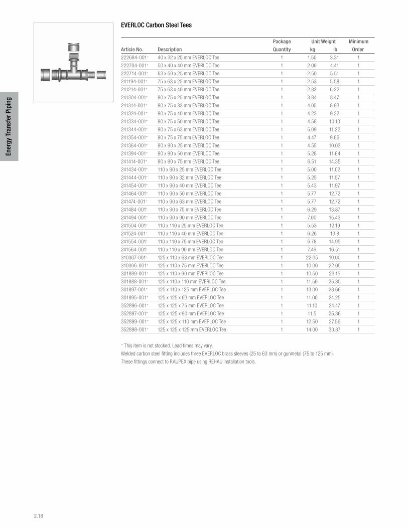
2.18
Ener
gy T
rans
fer P
ipin
g
EVERLOC Carbon Steel Tees
Package Unit Weight Minimum
Article No. Description Quantity kg lb Order
222684-001+ 40 x 32 x 25 mm EVERLOC Tee 1 1.50 3.31 1
222704-001+ 50 x 40 x 40 mm EVERLOC Tee 1 2.00 4.41 1
222714-001+ 63 x 50 x 25 mm EVERLOC Tee 1 2.50 5.51 1
241194-001+ 75 x 63 x 25 mm EVERLOC Tee 1 2.53 5.58 1
241214-001+ 75 x 63 x 40 mm EVERLOC Tee 1 2.82 6.22 1
241304-001+ 90 x 75 x 25 mm EVERLOC Tee 1 3.84 8.47 1
241314-001+ 90 x 75 x 32 mm EVERLOC Tee 1 4.05 8.93 1
241324-001+ 90 x 75 x 40 mm EVERLOC Tee 1 4.23 9.32 1
241334-001+ 90 x 75 x 50 mm EVERLOC Tee 1 4.58 10.10 1
241344-001+ 90 x 75 x 63 mm EVERLOC Tee 1 5.09 11.22 1
241354-001+ 90 x 75 x 75 mm EVERLOC Tee 1 4.47 9.86 1
241364-001+ 90 x 90 x 25 mm EVERLOC Tee 1 4.55 10.03 1
241394-001+ 90 x 90 x 50 mm EVERLOC Tee 1 5.28 11.64 1
241414-001+ 90 x 90 x 75 mm EVERLOC Tee 1 6.51 14.35 1
241434-001+ 110 x 90 x 25 mm EVERLOC Tee 1 5.00 11.02 1
241444-001+ 110 x 90 x 32 mm EVERLOC Tee 1 5.25 11.57 1
241454-001+ 110 x 90 x 40 mm EVERLOC Tee 1 5.43 11.97 1
241464-001+ 110 x 90 x 50 mm EVERLOC Tee 1 5.77 12.72 1
241474-001+ 110 x 90 x 63 mm EVERLOC Tee 1 5.77 12.72 1
241484-001+ 110 x 90 x 75 mm EVERLOC Tee 1 6.29 13.87 1
241494-001+ 110 x 90 x 90 mm EVERLOC Tee 1 7.00 15.43 1
241504-001+ 110 x 110 x 25 mm EVERLOC Tee 1 5.53 12.19 1
241524-001+ 110 x 110 x 40 mm EVERLOC Tee 1 6.26 13.8 1
241554-001+ 110 x 110 x 75 mm EVERLOC Tee 1 6.78 14.95 1
241564-001+ 110 x 110 x 90 mm EVERLOC Tee 1 7.49 16.51 1
310307-001+ 125 x 110 x 63 mm EVERLOC Tee 1 22.05 10.00 1
310306-001+ 125 x 110 x 75 mm EVERLOC Tee 1 10.00 22.05 1
301889-001+ 125 x 110 x 90 mm EVERLOC Tee 1 10.50 23.15 1
301888-001+ 125 x 110 x 110 mm EVERLOC Tee 1 11.50 25.35 1
301897-001+ 125 x 110 x 125 mm EVERLOC Tee 1 13.00 28.66 1
301895-001+ 125 x 125 x 63 mm EVERLOC Tee 1 11.00 24.25 1
352896-001+ 125 x 125 x 75 mm EVERLOC Tee 1 11.10 24.47 1
352897-001+ 125 x 125 x 90 mm EVERLOC Tee 1 11.5 25.36 1
352899-001+ 125 x 125 x 110 mm EVERLOC Tee 1 12.50 27.56 1
352898-001+ 125 x 125 x 125 mm EVERLOC Tee 1 14.00 30.87 1
+ This item is not stocked. Lead times may vary.
Welded carbon steel fitting includes three EVERLOC brass sleeves (25 to 63 mm) or gunmetal (75 to 125 mm).
These fittings connect to RAUPEX pipe using REHAU installation tools.
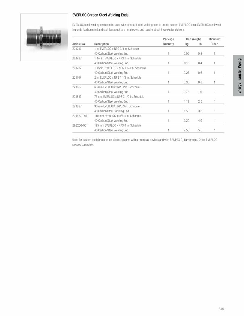
2.19
Ener
gy T
rans
fer P
ipin
g
EVERLOC Carbon Steel Welding Ends
EVERLOC steel welding ends can be used with standard steel welding tees to create custom EVERLOC tees. EVERLOC steel weld-
ing ends (carbon steel and stainless steel) are not stocked and require about 8 weeks for delivery.
Package Unit Weight Minimum
Article No. Description Quantity kg lb Order
221717 1 in. EVERLOC x NPS 3/4 in. Schedule
40 Carbon Steel Welding End 1 0.09 0.2 1
221727 1 1/4 in. EVERLOC x NPS 1 in. Schedule
40 Carbon Steel Welding End 1 0.16 0.4 1
221737 1 1/2 in. EVERLOC x NPS 1 1/4 in. Schedule
40 Carbon Steel Welding End 1 0.27 0.6 1
221747 2 in. EVERLOC x NPS 1 1/2 in. Schedule
40 Carbon Steel Welding End 1 0.36 0.8 1
221807 63 mm EVERLOC x NPS 2 in. Schedule
40 Carbon Steel Welding End 1 0.73 1.6 1
221817 75 mm EVERLOC x NPS 2 1/2 in. Schedule
40 Carbon Steel Welding End 1 1.13 2.5 1
221827 90 mm EVERLOC x NPS 3 in. Schedule
40 Carbon Steel Welding End 1 1.50 3.3 1
221837-001 110 mm EVERLOC x NPS 4 in. Schedule
40 Carbon Steel Welding End 1 2.20 4.9 1
298256-001 125 mm EVERLOC x NPS 4 in. Schedule
40 Carbon Steel Welding End 1 2.50 5.5 1
Used for custom tee fabrication on closed systems with air removal devices and with RAUPEX O2 barrier pipe. Order EVERLOC
sleeves separately.
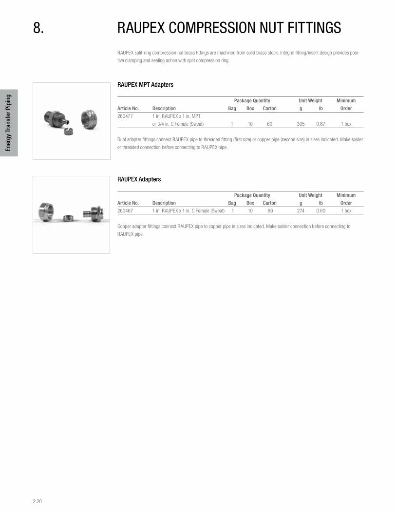
2.20
Ener
gy T
rans
fer P
ipin
g
8. raupEX coMprEssion nuT fiTTingsRAUPEX split-ring compression nut brass fittings are machined from solid brass stock. Integral fitting/insert design provides posi-
tive clamping and sealing action with split compression ring.
RAUPEX MPT Adapters
Package Quantity Unit Weight Minimum
Article No. Description Bag Box Carton g lb Order
260477 1 in. RAUPEX x 1 in. MPT
or 3/4 in. C Female (Sweat) 1 10 60 305 0.67 1 box
Dual adapter fittings connect RAUPEX pipe to threaded fitting (first size) or copper pipe (second size) in sizes indicated. Make solder
or threaded connection before connecting to RAUPEX pipe.
RAUPEX Adapters
Package Quantity Unit Weight Minimum
Article No. Description Bag Box Carton g lb Order
260467 1 in. RAUPEX x 1 in. C Female (Sweat) 1 10 60 274 0.60 1 box
Copper adapter fittings connect RAUPEX pipe to copper pipe in sizes indicated. Make solder connection before connecting to
RAUPEX pipe.
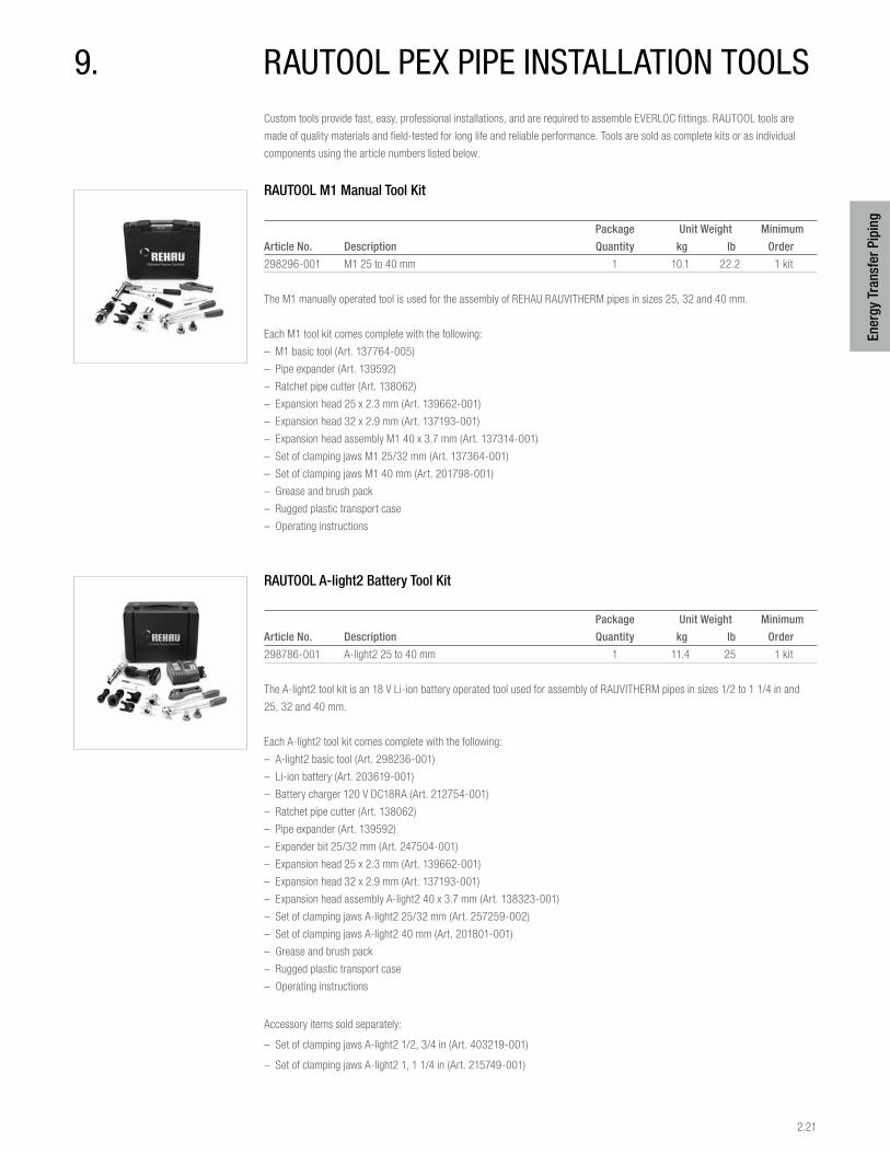
2.21
Ener
gy T
rans
fer P
ipin
g
9. rauTool pEX pipE insTallaTion ToolsCustom tools provide fast, easy, professional installations, and are required to assemble EVERLOC fittings. RAUTOOL tools are
made of quality materials and field-tested for long life and reliable performance. Tools are sold as complete kits or as individual
components using the article numbers listed below.
RAUTOOL M1 Manual Tool Kit
Package Unit Weight Minimum
Article No. Description Quantity kg lb Order
298296-001 M1 25 to 40 mm 1 10.1 22.2 1 kit
The M1 manually operated tool is used for the assembly of REHAU RAUVITHERM pipes in sizes 25, 32 and 40 mm.
Each M1 tool kit comes complete with the following:
– M1 basic tool (Art. 137764-005)
– Pipe expander (Art. 139592)
– Ratchet pipe cutter (Art. 138062)
– Expansion head 25 x 2.3 mm (Art. 139662-001)
– Expansion head 32 x 2.9 mm (Art. 137193-001)
– Expansion head assembly M1 40 x 3.7 mm (Art. 137314-001)
– Set of clamping jaws M1 25/32 mm (Art. 137364-001)
– Set of clamping jaws M1 40 mm (Art. 201798-001)
– Grease and brush pack
– Rugged plastic transport case
– Operating instructions
RAUTOOL A-light2 Battery Tool Kit
Package Unit Weight Minimum
Article No. Description Quantity kg lb Order
298786-001 A-light2 25 to 40 mm 1 11.4 25 1 kit
The A-light2 tool kit is an 18 V Li-ion battery operated tool used for assembly of RAUVITHERM pipes in sizes 1/2 to 1 1/4 in and
25, 32 and 40 mm.
Each A-light2 tool kit comes complete with the following:
– A-light2 basic tool (Art. 298236-001)
– Li-ion battery (Art. 203619-001)
– Battery charger 120 V DC18RA (Art. 212754-001)
– Ratchet pipe cutter (Art. 138062)
– Pipe expander (Art. 139592)
– Expander bit 25/32 mm (Art. 247504-001)
– Expansion head 25 x 2.3 mm (Art. 139662-001)
– Expansion head 32 x 2.9 mm (Art. 137193-001)
– Expansion head assembly A-light2 40 x 3.7 mm (Art. 138323-001)
– Set of clamping jaws A-light2 25/32 mm (Art. 257259-002)
– Set of clamping jaws A-light2 40 mm (Art. 201801-001)
– Grease and brush pack
– Rugged plastic transport case
– Operating instructions
Accessory items sold separately:
– Set of clamping jaws A-light2 1/2, 3/4 in (Art. 403219-001)
– Set of clamping jaws A-light2 1, 1 1/4 in (Art. 215749-001)
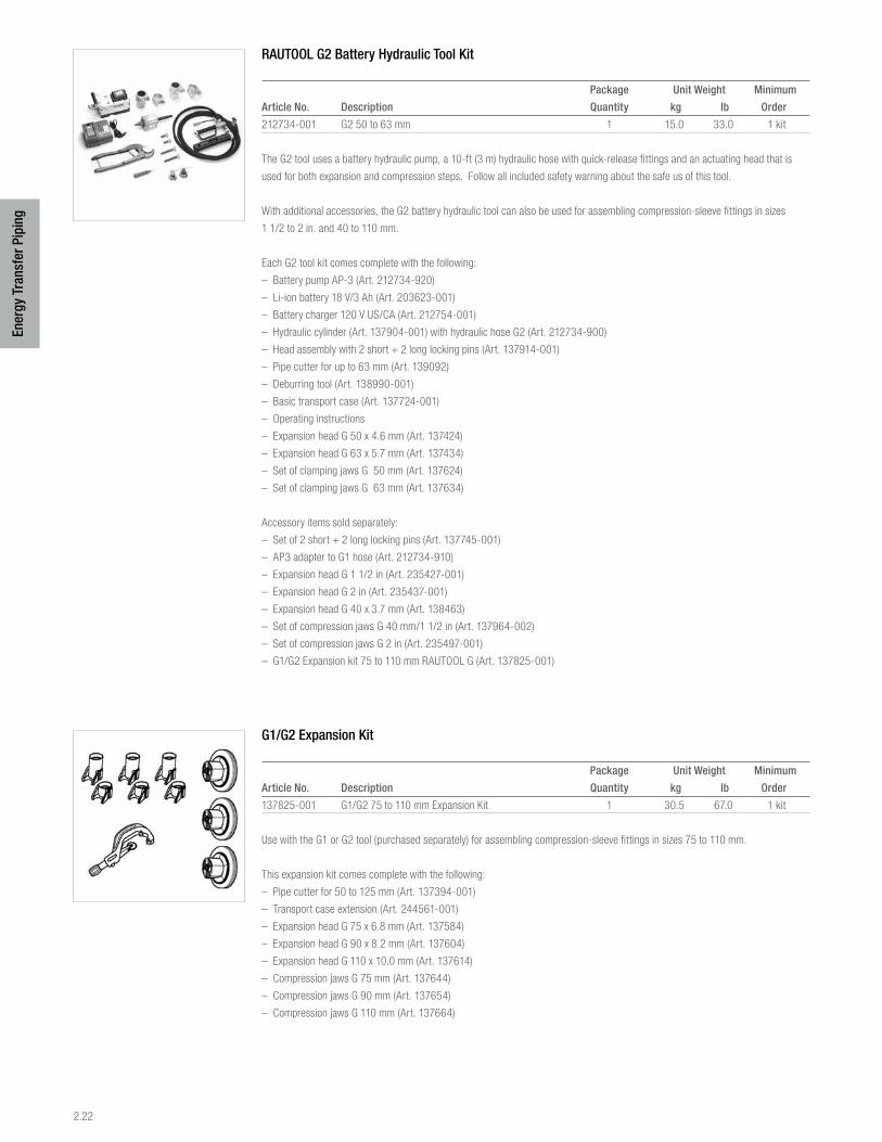
2.22
Ener
gy T
rans
fer P
ipin
g
RAUTOOL G2 Battery Hydraulic Tool Kit
Package Unit Weight Minimum
Article No. Description Quantity kg lb Order
212734-001 G2 50 to 63 mm 1 15.0 33.0 1 kit
The G2 tool uses a battery hydraulic pump, a 10-ft (3 m) hydraulic hose with quick-release fittings and an actuating head that is
used for both expansion and compression steps. Follow all included safety warning about the safe us of this tool.
With additional accessories, the G2 battery hydraulic tool can also be used for assembling compression-sleeve fittings in sizes
1 1/2 to 2 in. and 40 to 110 mm.
Each G2 tool kit comes complete with the following:
– Battery pump AP-3 (Art. 212734-920)
– Li-ion battery 18 V/3 Ah (Art. 203623-001)
– Battery charger 120 V US/CA (Art. 212754-001)
– Hydraulic cylinder (Art. 137904-001) with hydraulic hose G2 (Art. 212734-900)
– Head assembly with 2 short + 2 long locking pins (Art. 137914-001)
– Pipe cutter for up to 63 mm (Art. 139092)
– Deburring tool (Art. 138990-001)
– Basic transport case (Art. 137724-001)
– Operating instructions
– Expansion head G 50 x 4.6 mm (Art. 137424)
– Expansion head G 63 x 5.7 mm (Art. 137434)
– Set of clamping jaws G 50 mm (Art. 137624)
– Set of clamping jaws G 63 mm (Art. 137634)
Accessory items sold separately:
– Set of 2 short + 2 long locking pins (Art. 137745-001)
– AP3 adapter to G1 hose (Art. 212734-910)
– Expansion head G 1 1/2 in (Art. 235427-001)
– Expansion head G 2 in (Art. 235437-001)
– Expansion head G 40 x 3.7 mm (Art. 138463)
– Set of compression jaws G 40 mm/1 1/2 in (Art. 137964-002)
– Set of compression jaws G 2 in (Art. 235497-001)
– G1/G2 Expansion kit 75 to 110 mm RAUTOOL G (Art. 137825-001)
G1/G2 Expansion Kit
Package Unit Weight Minimum
Article No. Description Quantity kg lb Order
137825-001 G1/G2 75 to 110 mm Expansion Kit 1 30.5 67.0 1 kit
Use with the G1 or G2 tool (purchased separately) for assembling compression-sleeve fittings in sizes 75 to 110 mm.
This expansion kit comes complete with the following:
– Pipe cutter for 50 to 125 mm (Art. 137394-001)
– Transport case extension (Art. 244561-001)
– Expansion head G 75 x 6.8 mm (Art. 137584)
– Expansion head G 90 x 8.2 mm (Art. 137604)
– Expansion head G 110 x 10.0 mm (Art. 137614)
– Compression jaws G 75 mm (Art. 137644)
– Compression jaws G 90 mm (Art. 137654)
– Compression jaws G 110 mm (Art. 137664)
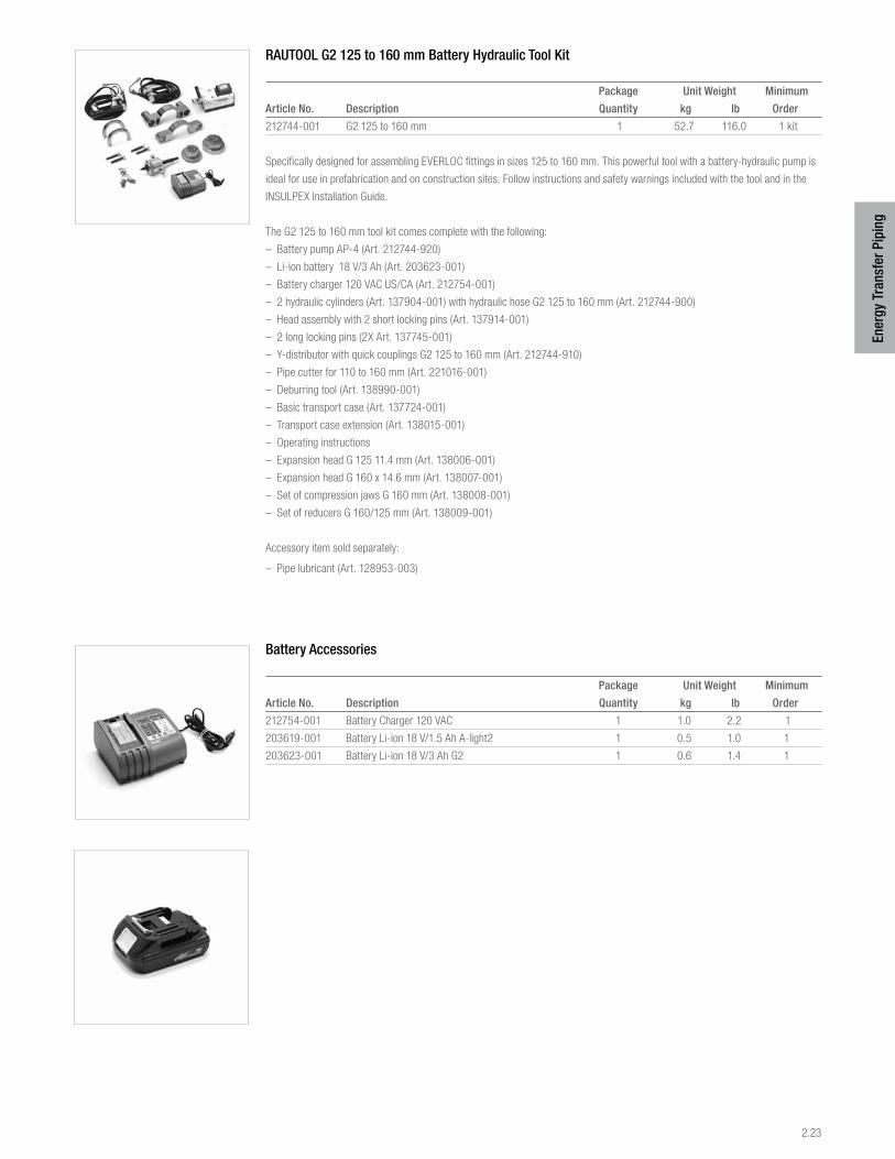
2.23
Ener
gy T
rans
fer P
ipin
g
RAUTOOL G2 125 to 160 mm Battery Hydraulic Tool Kit
Package Unit Weight Minimum
Article No. Description Quantity kg lb Order
212744-001 G2 125 to 160 mm 1 52.7 116.0 1 kit
Specifically designed for assembling EVERLOC fittings in sizes 125 to 160 mm. This powerful tool with a battery-hydraulic pump is
ideal for use in prefabrication and on construction sites. Follow instructions and safety warnings included with the tool and in the
INSULPEX Installation Guide.
The G2 125 to 160 mm tool kit comes complete with the following:
– Battery pump AP-4 (Art. 212744-920)
– Li-ion battery 18 V/3 Ah (Art. 203623-001)
– Battery charger 120 VAC US/CA (Art. 212754-001)
– 2 hydraulic cylinders (Art. 137904-001) with hydraulic hose G2 125 to 160 mm (Art. 212744-900)
– Head assembly with 2 short locking pins (Art. 137914-001)
– 2 long locking pins (2X Art. 137745-001)
– Y-distributor with quick couplings G2 125 to 160 mm (Art. 212744-910)
– Pipe cutter for 110 to 160 mm (Art. 221016-001)
– Deburring tool (Art. 138990-001)
– Basic transport case (Art. 137724-001)
– Transport case extension (Art. 138015-001)
– Operating instructions
– Expansion head G 125 11.4 mm (Art. 138006-001)
– Expansion head G 160 x 14.6 mm (Art. 138007-001)
– Set of compression jaws G 160 mm (Art. 138008-001)
– Set of reducers G 160/125 mm (Art. 138009-001)
Accessory item sold separately:
– Pipe lubricant (Art. 128953-003)
Battery Accessories
Package Unit Weight Minimum
Article No. Description Quantity kg lb Order
212754-001 Battery Charger 120 VAC 1 1.0 2.2 1
203619-001 Battery Li-ion 18 V/1.5 Ah A-light2 1 0.5 1.0 1
203623-001 Battery Li-ion 18 V/3 Ah G2 1 0.6 1.4 1
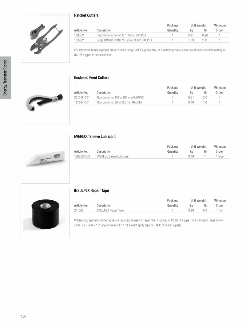
2.24
Ener
gy T
rans
fer P
ipin
g
Ratchet Cutters
Package Unit Weight Minimum
Article No. Description Quantity kg lb Order
138062 Ratchet Cutter for up to 1 1/2 in. RAUPEX 1 0.41 0.90 1
139092 Large Ratchet Cutter for up to 63 mm RAUPEX 1 1.09 2.41 1
It is important to use a proper cutter when cutting RAUPEX pipes. RAUPEX cutters provide clean, square and accurate cutting of
RAUPEX pipes in sizes indicated.
Enclosed Feed Cutters
Package Unit Weight Minimum
Article No. Description Quantity kg lb Order
221016-001 Pipe Cutter for 110 to 160 mm RAUPEX 1 0.91 2.0 1
137394-001 Pipe Cutter for 50 to 125 mm RAUPEX 1 0.46 1.0 1
EVERLOC Sleeve Lubricant
Package Unit Weight Minimum
Article No. Description Quantity kg lb Order
128953-003 EVERLOC Sleeve Lubricant 1 0.49 1.1 1 tube
INSULPEX Repair Tape
Package Unit Weight Minimum
Article No. Description Quantity kg lb Order
241002 INSULPEX Repair Tape 1 0.26 0.6 1 roll
Waterproof, synthetic rubber adhesive tape can be used to repair the PE casing of INSULPEX pipe if it is damaged. Tape dimen-
sions: 2 in. wide x 15' long (50 mm x 4.57 m). Do not apply tape to RAUPEX carrier pipe(s).
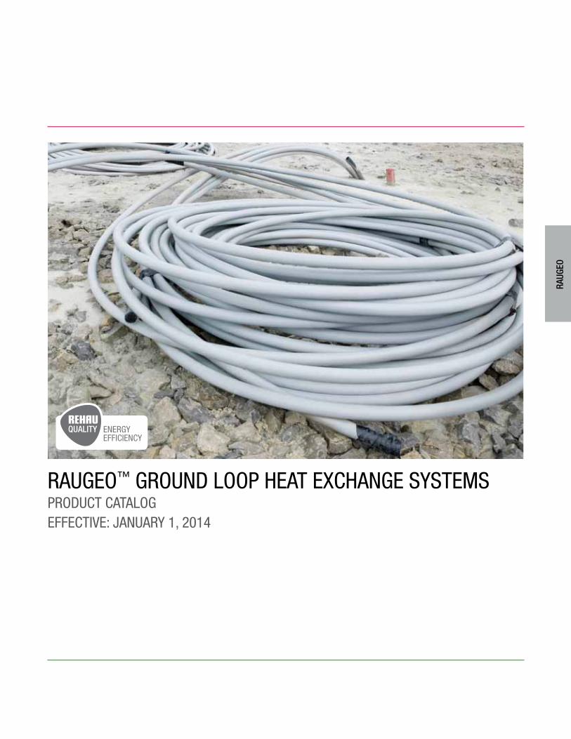
RAUGEO™ GROUnd lOOp hEAt ExchAnGE systEms pROdUct cAtAlOGEffEctivE: JAnUARy 1, 2014
RAUG
EO
ENERGYEFFICIENCY
3.2
RAUG
EO
1. RAUGEO™ Ground Loops . . . . . . . . . . . . . . . . . . . . . . . . . . . 3.3
2. PRO-BALANCE® 1 1/4 in. Manifolds. . . . . . . . . . . . . . . . . . . 3.6
3. HKV 1 1/4 in. Manifolds . . . . . . . . . . . . . . . . . . . . . . . . . . . . 3.7
4. PRO-BALANCE XP Manifolds . . . . . . . . . . . . . . . . . . . . . . . . 3.8
5. PRO-BALANCE XP Accessories . . . . . . . . . . . . . . . . . . . . . 3.10
6. EVERLOC® Fittings . . . . . . . . . . . . . . . . . . . . . . . . . . . . . . . 3.12
7. RAUTOOL™ PEX Pipe Installation Tools . . . . . . . . . . . . . . . 3.14
tAblE Of cOntEnts
For updates to this publication and the most current technical instructions, safety information and manufacturer’s recommendations, visit na.rehau.com/resourcecenter
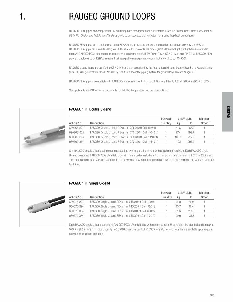
3.3
RAUG
EO
RAUGEO PEXa pipes and compression-sleeve fittings are recognized by the International Ground Source Heat Pump Association’s
(IGSHPA) Design and Installation Standards guide as an accepted piping system for ground loop heat exchangers.
RAUGEO PEXa pipes are manufactured using REHAU’s high-pressure peroxide method for crosslinked polyethylene (PEXa).
RAUGEO PEXa pipe has a coextruded grey PE UV shield that protects the pipe against ultraviolet light (sunlight) for an extended
time. All RAUGEO PEXa pipe meets or exceeds the requirements of ASTM F876, F877, CSA B137.5, and PPI TR-3. RAUGEO PEXa
pipe is manufactured by REHAU in a plant using a quality management system that is certified to ISO 9001.
RAUGEO ground loops are certified to CSA C448 and are recognized by the International Ground Source Heat Pump Association's
(IGSHPA) Design and Installation Standards guide as an accepted piping system for ground loop heat exchangers.
RAUGEO PEXa pipe is compatible with RAUPEX compression nut fittings and fittings certified to ASTM F2080 and CSA B137.5.
See applicable REHAU technical documents for detailed temperature and pressure ratings.
RAUGEO 1 in. Double U-bend
Package Unit Weight Minimum
Article No. Description Quantity kg lb Order
630366-224 RAUGEO Double U-bend PEXa 1 in. CTS 210 ft Coil (840 ft) 1 71.6 157.8 1
630366-924 RAUGEO Double U-bend PEXa 1 in. CTS 260 ft Coil (1,040 ft) 1 87.4 192.7 1
630366-324 RAUGEO Double U-bend PEXa 1 in. CTS 310 ft Coil (1,240 ft) 1 103.3 227.7 1
630366-374 RAUGEO Double U-bend PEXa 1 in. CTS 360 ft Coil (1,440 ft) 1 119.1 262.6 1
One RAUGEO double U-bend coil comes packaged as two single U-bend coils with attachment hardware. Each RAUGEO single
U-bend comprises RAUGEO PEXa UV shield pipe with reinforced resin U-bend tip. 1 in. pipe inside diameter is 0.875 in (22.2 mm).
1 in. pipe capacity is 0.0316 US gallons per foot (0.3939 l/m). Custom coil lengths are available upon request, but with an extended
lead time.
RAUGEO 1 in. Single U-bend
Package Unit Weight Minimum
Article No. Description Quantity kg lb Order
630376-224 RAUGEO Single U-bend PEXa 1 in. CTS 210 ft Coil (420 ft) 1 35.8 78.9 1
630376-924 RAUGEO Single U-bend PEXa 1 in. CTS 260 ft Coil (520 ft) 1 43.7 96.4 1
630376-324 RAUGEO Single U-bend PEXa 1 in. CTS 310 ft.Coil (620 ft) 1 51.6 113.8 1
630376-374 RAUGEO Single U-bend PEXa 1 in. CTS 360 ft.Coil (720 ft) 1 59.6 131.3 1
Each RAUGEO single U-bend comprises RAUGEO PEXa UV shield pipe with reinforced resin U-bend tip. 1 in. pipe inside diameter is
0.875 in (22.2 mm). 1 in. pipe capacity is 0.0316 US gallons per foot (0.3939 l/m). Custom coil lengths are available upon request,
but with an extended lead time.
1. RAUGEO GROUnd lOOps
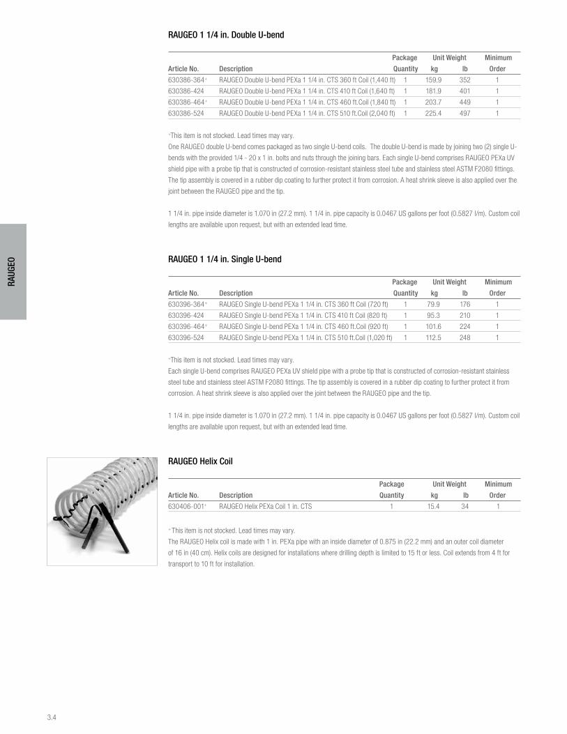
3.4
RAUG
EO
RAUGEO 1 1/4 in. Double U-bend
Package Unit Weight Minimum
Article No. Description Quantity kg lb Order
630386-364+ RAUGEO Double U-bend PEXa 1 1/4 in. CTS 360 ft Coil (1,440 ft) 1 159.9 352 1
630386-424 RAUGEO Double U-bend PEXa 1 1/4 in. CTS 410 ft Coil (1,640 ft) 1 181.9 401 1
630386-464+ RAUGEO Double U-bend PEXa 1 1/4 in. CTS 460 ft.Coil (1,840 ft) 1 203.7 449 1
630386-524 RAUGEO Double U-bend PEXa 1 1/4 in. CTS 510 ft.Coil (2,040 ft) 1 225.4 497 1
+This item is not stocked. Lead times may vary.
One RAUGEO double U-bend comes packaged as two single U-bend coils. The double U-bend is made by joining two (2) single U-
bends with the provided 1/4 - 20 x 1 in. bolts and nuts through the joining bars. Each single U-bend comprises RAUGEO PEXa UV
shield pipe with a probe tip that is constructed of corrosion-resistant stainless steel tube and stainless steel ASTM F2080 fittings.
The tip assembly is covered in a rubber dip coating to further protect it from corrosion. A heat shrink sleeve is also applied over the
joint between the RAUGEO pipe and the tip.
1 1/4 in. pipe inside diameter is 1.070 in (27.2 mm). 1 1/4 in. pipe capacity is 0.0467 US gallons per foot (0.5827 l/m). Custom coil
lengths are available upon request, but with an extended lead time.
RAUGEO 1 1/4 in. Single U-bend
Package Unit Weight Minimum
Article No. Description Quantity kg lb Order
630396-364+ RAUGEO Single U-bend PEXa 1 1/4 in. CTS 360 ft Coil (720 ft) 1 79.9 176 1
630396-424 RAUGEO Single U-bend PEXa 1 1/4 in. CTS 410 ft Coil (820 ft) 1 95.3 210 1
630396-464+ RAUGEO Single U-bend PEXa 1 1/4 in. CTS 460 ft.Coil (920 ft) 1 101.6 224 1
630396-524 RAUGEO Single U-bend PEXa 1 1/4 in. CTS 510 ft.Coil (1,020 ft) 1 112.5 248 1
+This item is not stocked. Lead times may vary.
Each single U-bend comprises RAUGEO PEXa UV shield pipe with a probe tip that is constructed of corrosion-resistant stainless
steel tube and stainless steel ASTM F2080 fittings. The tip assembly is covered in a rubber dip coating to further protect it from
corrosion. A heat shrink sleeve is also applied over the joint between the RAUGEO pipe and the tip.
1 1/4 in. pipe inside diameter is 1.070 in (27.2 mm). 1 1/4 in. pipe capacity is 0.0467 US gallons per foot (0.5827 l/m). Custom coil
lengths are available upon request, but with an extended lead time.
RAUGEO Helix Coil
Package Unit Weight Minimum
Article No. Description Quantity kg lb Order
630406-001+ RAUGEO Helix PEXa Coil 1 in. CTS 1 15.4 34 1
+ This item is not stocked. Lead times may vary.
The RAUGEO Helix coil is made with 1 in. PEXa pipe with an inside diameter of 0.875 in (22.2 mm) and an outer coil diameter
of 16 in (40 cm). Helix coils are designed for installations where drilling depth is limited to 15 ft or less. Coil extends from 4 ft for
transport to 10 ft for installation.
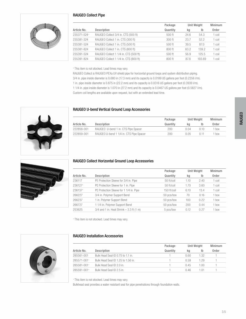
3.5
RAUG
EO
RAUGEO Collect Pipe
Package Unit Weight Minimum
Article No. Description Quantity kg lb Order
235371-524+ RAUGEO Collect 3/4 in. CTS (500 ft) 500 ft 24.6 54.3 1 coil
235381-324 RAUGEO Collect 1 in. CTS (300 ft) 300 ft 23.7 52.2 1 coil
235381-524 RAUGEO Collect 1 in. CTS (500 ft) 500 ft 39.5 87.0 1 coil
235381-824 RAUGEO Collect 1 in. CTS (800 ft) 800 ft 63.2 139.2 1 coil
235391-524 RAUGEO Collect 1 1/4 in. CTS (500 ft) 500 ft 56.9 125.5 1 coil
235391-824 RAUGEO Collect 1 1/4 in. CTS (800 ft) 800 ft 87.8 193.69 1 coil
+ This item is not stocked. Lead times may vary.
RAUGEO Collect is RAUGEO PEXa UV shield pipe for horizontal ground loops and system distribution piping.
3/4 in. pipe inside diameter is 0.680 in (17.3 mm) and its capacity is 0.0189 US gallons per foot (0.2356 l/m).
1 in. pipe inside diameter is 0.875 in (22.2 mm) and its capacity is 0.0316 US gallons per foot (0.3939 l/m).
1 1/4 in. pipe inside diameter is 1.070 in (27.2 mm) and its capacity is 0.0467 US gallons per foot (0.5827 l/m).
Custom coil lengths are available upon request, but with an extended lead time.
RAUGEO U-bend Vertical Ground Loop Accessories
Package Unit Weight Minimum
Article No. Description Quantity kg lb Order
222858-001 RAUGEO U-bend 1 in. CTS Pipe Spacer 200 0.04 0.10 1 box
222859-001 RAUGEO U-bend 1 1/4 in. CTS Pipe Spacer 200 0.05 0.11 1 box
RAUGEO Collect Horizontal Ground Loop Accessories
Package Unit Weight Minimum
Article No. Description Quantity kg lb Order
236117 PE Protection Sleeve for 3/4 in. Pipe 50 ft/coil 1.10 2.40 1 coil
236127+ PE Protection Sleeve for 1 in. Pipe 50 ft/coil 1.70 3.60 1 coil
236137+ PE Protection Sleeve for 1 1/4 in. Pipe 150 ft/coil 6.10 13.4 1 coil
266227 3/4 in. Polymer Support Bend 50 pcs/box 70 0.16 1 box
266237 1 in. Polymer Support Bend 50 pcs/box 100 0.22 1 box
266727 1 1/4 in. Polymer Support Bend 50 pcs/box 200 0.44 1 box
253625 3/4 and 1 in. Heat Shrink – 3.3 ft (1 m) 5 pcs/box 0.12 0.27 1 box
+ This item is not stocked. Lead times may vary.
RAUGEO Installation Accessories
Package Unit Weight Minimum
Article No. Description Quantity kg lb Order
285561-001 Bulk Head Seal ID 0.75 to 1.1 in. 1 0.60 1.32 1
285571-001+ Bulk Head Seal ID 1.25 to 1.56 in. 1 0.59 1.29 1
285581-001+ Bulk Head Seal ID 2.0 in. 1 0.45 1.00 1
285591-001+ Bulk Head Seal ID 2.5 in. 1 0.46 1.01 1
+ This item is not stocked. Lead times may vary.
Bulkhead seal provides a water resistant seal for pipe penetrations through foundation walls.
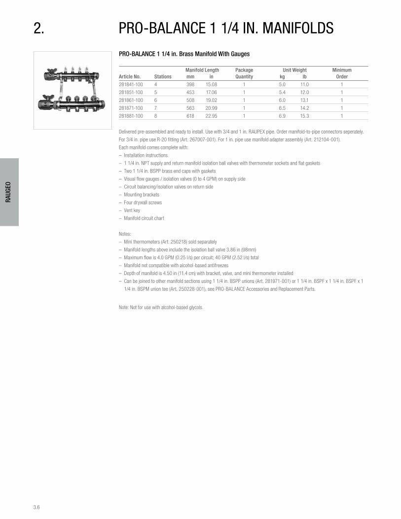
3.6
RAUG
EO
PRO-BALANCE 1 1/4 in. Brass Manifold With Gauges
Manifold Length Package Unit Weight MinimumArticle No. Stations mm in Quantity kg lb Order
281841-100 4 398 15.08 1 5.0 11.0 1
281851-100 5 453 17.06 1 5.4 12.0 1
281861-100 6 508 19.02 1 6.0 13.1 1
281871-100 7 563 20.99 1 6.5 14.2 1
281881-100 8 618 22.95 1 6.9 15.3 1
Delivered pre-assembled and ready to install. Use with 3/4 and 1 in. RAUPEX pipe. Order manifold-to-pipe connectors seperately.
For 3/4 in. pipe use R-20 fitting (Art. 267007-001). For 1 in. pipe use manifold adapter assembly (Art. 212104-001).
Each manifold comes complete with:
– Installation instructions
– 1 1/4 in. NPT supply and return manifold isolation ball valves with thermometer sockets and flat gaskets
– Two 1 1/4 in. BSPP brass end caps with gaskets
– Visual flow gauges / isolation valves (0 to 4 GPM) on supply side
– Circuit balancing/isolation valves on return side
– Mounting brackets
– Four drywall screws
– Vent key
– Manifold circuit chart
Notes:
– Mini thermometers (Art. 250218) sold separately
– Manifold lengths above include the isolation ball valve 3.86 in (98mm)
– Maximum flow is 4.0 GPM (0.25 l/s) per circuit; 40 GPM (2.52 l/s) total
– Manifold not compatible with alcohol-based antifreezes
– Depth of manifold is 4.50 in (11.4 cm) with bracket, valve, and mini thermometer installed
– Can be joined to other manifold sections using 1 1/4 in. BSPP unions (Art. 281971-001) or 1 1/4 in. BSPF x 1 1/4 in. BSPF x 1
1/4 in. BSPM union tee (Art. 250228-001), see PRO-BALANCE Accessories and Replacement Parts.
Note: Not for use with alcohol-based glycols.
2. pRO-bAlAncE 1 1/4 in. mAnifOlds
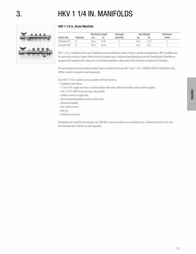
3.7
RAUG
EO
3. hKv 1 1/4 in. mAnifOldsHKV 1 1/4 in. Brass Manifold
Manifold Length Package Unit Weight MinimumArticle No. Stations cm in Quantity kg lb Order
215528-001 4 30.0 11.81 1 5.0 11.0 1
215529-001 6 41.0 16.14 1 5.4 13.1 1
HKV 1 1/4 in. manifolds are for use in distributing and regulating the volume of flow in geothermal applications. HKV manifolds may
be used with a variety of system fluids including propylene glycol, ethylene-based glycols and alcohol-based glycols. Manifold are
equipped with supply/shutoff valves and circuit balancing isolation valves which allow individual complete circuit isolation.
Pre-assembled and factory pressure-tested, these manifolds are for use with 1 and 1 1/4 in. RAUGEO PEXa UV shield pipe using
REHAU manifold connections (sold separately).
Each HKV 1 1/4 in. manifold comes complete with the following:
– Installation instructions
– 1 1/4 in. NPT supply and return manifold isolation ball valves with thermometer sockets and flat gaskets
– Two 1 1/4 in. BSPP brass end caps with gaskets
– Isolation valves on supply side
– Circuit balancing/isolation valves on return side
– Mounting brackets
– Four drywall screws
– Vent key
– Manifold circuit chart
Compatible with manifold valve actuator (Art. 260166), may be mounted in any orientation (e.g., inverted, horizontal, etc.), mini
thermometers (Art. 250218) are sold separately.
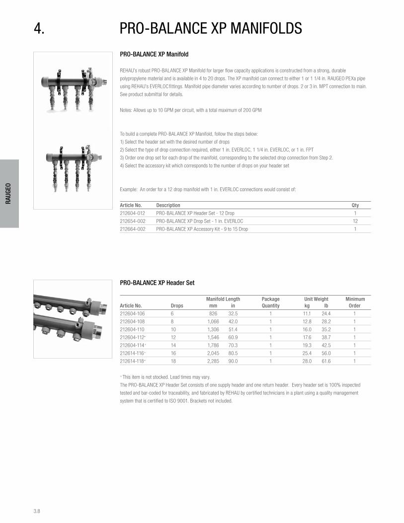
3.8
RAUG
EO
PRO-BALANCE XP Manifold
REHAU’s robust PRO-BALANCE XP Manifold for larger flow capacity applications is constructed from a strong, durable
polypropylene material and is available in 4 to 20 drops. The XP manifold can connect to either 1 or 1 1/4 in. RAUGEO PEXa pipe
using REHAU’s EVERLOC fittings. Manifold pipe diameter varies according to number of drops. 2 or 3 in. MPT connection to main.
See product submittal for details.
Notes: Allows up to 10 GPM per circuit, with a total maximum of 200 GPM
To build a complete PRO-BALANCE XP Manifold, follow the steps below:
1) Select the header set with the desired number of drops
2) Select the type of drop connection required, either 1 in. EVERLOC, 1 1/4 in. EVERLOC, or 1 in. FPT
3) Order one drop set for each drop of the manifold, corresponding to the selected drop connection from Step 2.
4) Select the accessory kit which corresponds to the number of drops on your header set
Example: An order for a 12 drop manifold with 1 in. EVERLOC connections would consist of:
Article No. Description Qty
212604-012 PRO-BALANCE XP Header Set - 12 Drop 1
212654-002 PRO-BALANCE XP Drop Set - 1 in. EVERLOC 12
212664-002 PRO-BALANCE XP Accessory Kit - 9 to 15 Drop 1
PRO-BALANCE XP Header Set
Manifold Length Package Unit Weight Minimum Article No. Drops mm in Quantity kg lb Order
212604-106 6 826 32.5 1 11.1 24.4 1
212604-108 8 1,066 42.0 1 12.8 28.2 1
212604-110 10 1,306 51.4 1 16.0 35.2 1
212604-112+ 12 1,546 60.9 1 17.6 38.7 1
212604-114+ 14 1,786 70.3 1 19.3 42.5 1
212614-116+ 16 2,045 80.5 1 25.4 56.0 1
212614-118+ 18 2,285 90.0 1 28.0 61.6 1
+ This item is not stocked. Lead times may vary.
The PRO-BALANCE XP Header Set consists of one supply header and one return header. Every header set is 100% inspected
tested and bar-coded for traceability, and fabricated by REHAU by certified technicians in a plant using a quality management
system that is certified to ISO 9001. Brackets not included.
4. pRO-bAlAncE xp mAnifOlds
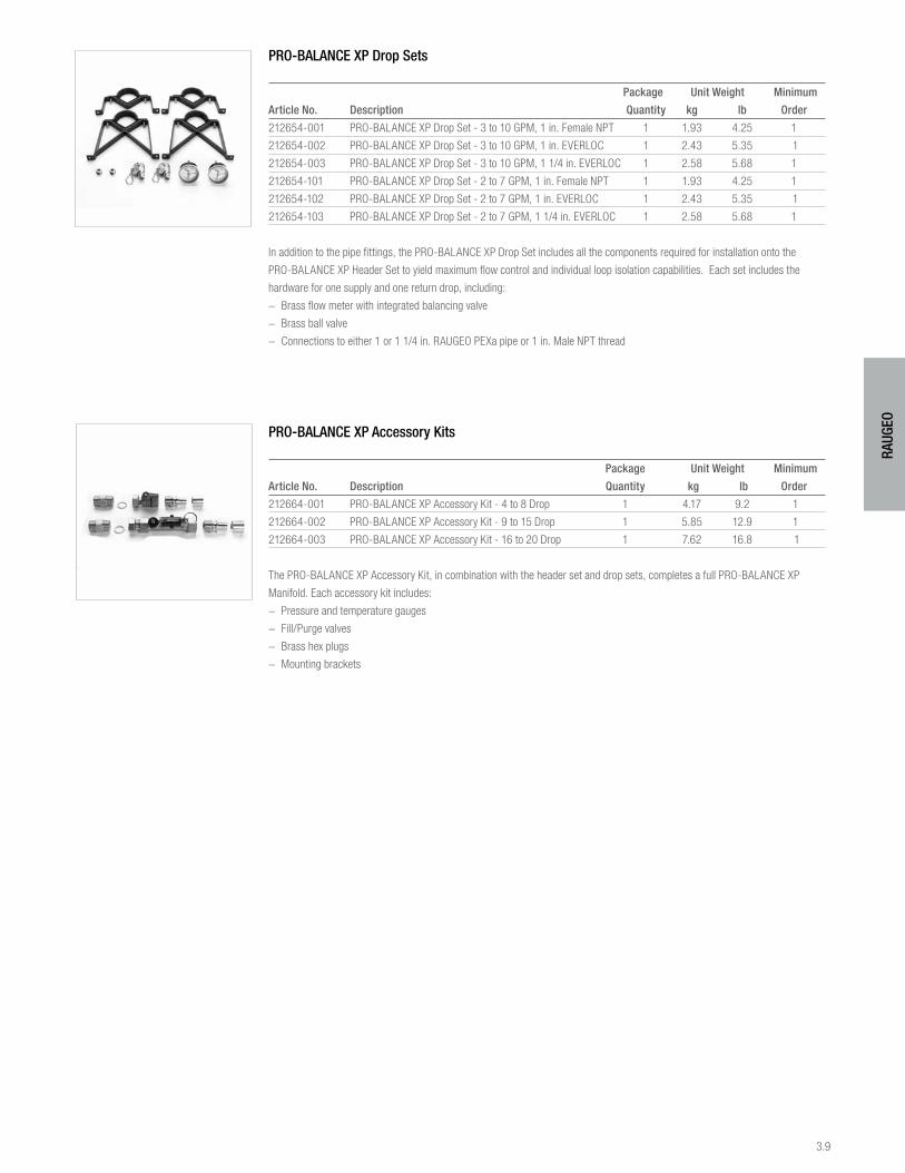
3.9
RAUG
EO
PRO-BALANCE XP Drop Sets
Package Unit Weight Minimum
Article No. Description Quantity kg lb Order
212654-001 PRO-BALANCE XP Drop Set - 3 to 10 GPM, 1 in. Female NPT 1 1.93 4.25 1
212654-002 PRO-BALANCE XP Drop Set - 3 to 10 GPM, 1 in. EVERLOC 1 2.43 5.35 1
212654-003 PRO-BALANCE XP Drop Set - 3 to 10 GPM, 1 1/4 in. EVERLOC 1 2.58 5.68 1
212654-101 PRO-BALANCE XP Drop Set - 2 to 7 GPM, 1 in. Female NPT 1 1.93 4.25 1
212654-102 PRO-BALANCE XP Drop Set - 2 to 7 GPM, 1 in. EVERLOC 1 2.43 5.35 1
212654-103 PRO-BALANCE XP Drop Set - 2 to 7 GPM, 1 1/4 in. EVERLOC 1 2.58 5.68 1
In addition to the pipe fittings, the PRO-BALANCE XP Drop Set includes all the components required for installation onto the
PRO-BALANCE XP Header Set to yield maximum flow control and individual loop isolation capabilities. Each set includes the
hardware for one supply and one return drop, including:
− Brass flow meter with integrated balancing valve
− Brass ball valve
− Connections to either 1 or 1 1/4 in. RAUGEO PEXa pipe or 1 in. Male NPT thread
PRO-BALANCE XP Accessory Kits
Package Unit Weight Minimum
Article No. Description Quantity kg lb Order
212664-001 PRO-BALANCE XP Accessory Kit - 4 to 8 Drop 1 4.17 9.2 1
212664-002 PRO-BALANCE XP Accessory Kit - 9 to 15 Drop 1 5.85 12.9 1
212664-003 PRO-BALANCE XP Accessory Kit - 16 to 20 Drop 1 7.62 16.8 1
The PRO-BALANCE XP Accessory Kit, in combination with the header set and drop sets, completes a full PRO-BALANCE XP
Manifold. Each accessory kit includes:
− Pressure and temperature gauges
− Fill/Purge valves
− Brass hex plugs
− Mounting brackets
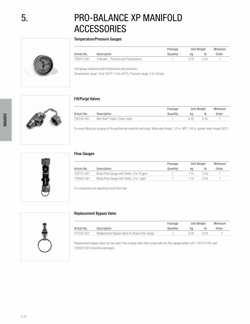
3.10
RAUG
EO
Temperature/Pressure Gauges
Package Unit Weight Minimum
Article No. Description Quantity kg lb Order
730013-001 Tridicator - Pressure and Temperature 1 0.16 0.35 1
This gauge measures both temperature and pressure.
Temperature range: 10 to 120°F (-12 to 49°C). Pressure range: 0 to 100 psi.
Fill/Purge Valves
Package Unit Weight Minimum
Article No. Description Quantity kg lb Order
730103-001 Mini-BallTM Valve / Drain Valve 1 0.20 0.45 1
For easy filling and purging of the geothermal manifold and loops. Male pipe thread, 1/2 in. MPT, 3/4 in. garden hose thread (GHT).
Flow Gauges
Package Unit Weight Minimum
Article No. Description Quantity kg lb Order
730173-001 Brass Flow Gauge with Setter, 3 to 10 gpm 1 1.14 2.50 1
730023-001 Brass Flow Gauge with Setter, 2 to 7 gpm 1 1.14 2.50 1
For measuring and adjusting circuit flow rate.
Replacement Bypass Valve
Package Unit Weight Minimum
Article No. Description Quantity kg lb Order
212724-001 Replacement Bypass Valve for Brass Flow Gauge 1 0.20 0.44 1
Replacement bypass valve can be used if the original valve that comes with the flow gauge setters (Art. 730173-001 and
730023-001) becomes damaged.
5. pRO-bAlAncE xp mAnifOld AccEssORiEs
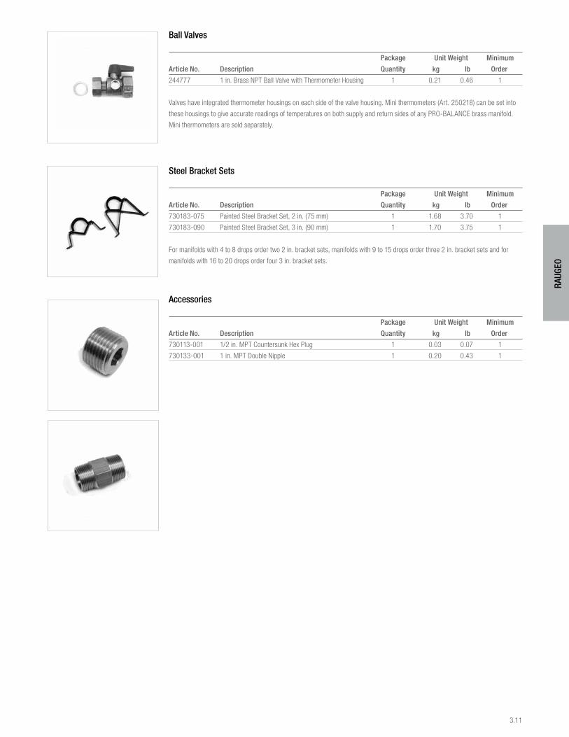
3.11
RAUG
EO
Ball Valves
Package Unit Weight Minimum
Article No. Description Quantity kg lb Order
244777 1 in. Brass NPT Ball Valve with Thermometer Housing 1 0.21 0.46 1
Valves have integrated thermometer housings on each side of the valve housing. Mini thermometers (Art. 250218) can be set into
these housings to give accurate readings of temperatures on both supply and return sides of any PRO-BALANCE brass manifold.
Mini thermometers are sold separately.
Steel Bracket Sets
Package Unit Weight Minimum
Article No. Description Quantity kg lb Order
730183-075 Painted Steel Bracket Set, 2 in. (75 mm) 1 1.68 3.70 1
730183-090 Painted Steel Bracket Set, 3 in. (90 mm) 1 1.70 3.75 1
For manifolds with 4 to 8 drops order two 2 in. bracket sets, manifolds with 9 to 15 drops order three 2 in. bracket sets and for
manifolds with 16 to 20 drops order four 3 in. bracket sets.
Accessories
Package Unit Weight Minimum
Article No. Description Quantity kg lb Order
730113-001 1/2 in. MPT Countersunk Hex Plug 1 0.03 0.07 1
730133-001 1 in. MPT Double Nipple 1 0.20 0.43 1
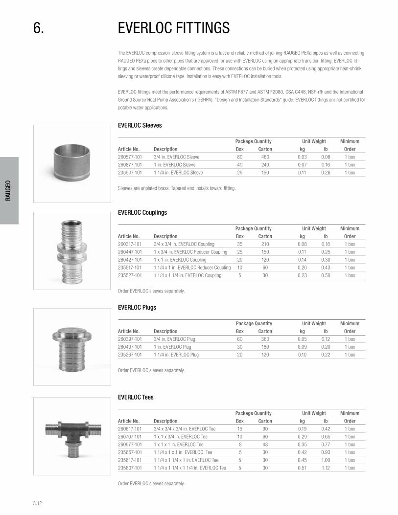
3.12
RAUG
EO
The EVERLOC compression-sleeve fitting system is a fast and reliable method of joining RAUGEO PEXa pipes as well as connecting
RAUGEO PEXa pipes to other pipes that are approved for use with EVERLOC using an appropriate transition fitting. EVERLOC fit-
tings and sleeves create dependable connections. These connections can be buried when protected using appropriate heat-shrink
sleeving or waterproof silicone tape. Installation is easy with EVERLOC installation tools.
EVERLOC fittings meet the performance requirements of ASTM F877 and ASTM F2080, CSA C448, NSF-rfh and the International
Ground Source Heat Pump Association’s (IGSHPA) "Design and Installation Standards" guide. EVERLOC fittings are not certified for
potable water applications.
EVERLOC Sleeves
Package Quantity Unit Weight Minimum
Article No. Description Box Carton kg lb Order
260577-101 3/4 in. EVERLOC Sleeve 80 480 0.03 0.08 1 box
260877-101 1 in. EVERLOC Sleeve 40 240 0.07 0.16 1 box
235507-101 1 1/4 in. EVERLOC Sleeve 25 150 0.11 0.26 1 box
Sleeves are unplated brass. Tapered end installs toward fitting.
EVERLOC Couplings
Package Quantity Unit Weight Minimum
Article No. Description Box Carton kg lb Order
260317-101 3/4 x 3/4 in. EVERLOC Coupling 35 210 0.08 0.18 1 box
260447-101 1 x 3/4 in. EVERLOC Reducer Coupling 25 150 0.11 0.25 1 box
260427-101 1 x 1 in. EVERLOC Coupling 20 120 0.14 0.30 1 box
235517-101 1 1/4 x 1 in. EVERLOC Reducer Coupling 10 60 0.20 0.43 1 box
235527-101 1 1/4 x 1 1/4 in. EVERLOC Coupling 5 30 0.23 0.50 1 box
Order EVERLOC sleeves separately.
EVERLOC Plugs
Package Quantity Unit Weight Minimum
Article No. Description Box Carton kg lb Order
260397-101 3/4 in. EVERLOC Plug 60 360 0.05 0.12 1 box
260497-101 1 in. EVERLOC Plug 30 180 0.09 0.20 1 box
235267-101 1 1/4 in. EVERLOC Plug 20 120 0.10 0.22 1 box
Order EVERLOC sleeves separately.
EVERLOC Tees
Package Quantity Unit Weight Minimum
Article No. Description Box Carton kg lb Order
260617-101 3/4 x 3/4 x 3/4 in. EVERLOC Tee 15 90 0.19 0.42 1 box
260707-101 1 x 1 x 3/4 in. EVERLOC Tee 10 60 0.29 0.65 1 box
260977-101 1 x 1 x 1 in. EVERLOC Tee 8 48 0.35 0.77 1 box
235657-101 1 1/4 x 1 x 1 in. EVERLOC Tee 5 30 0.42 0.93 1 box
235617-101 1 1/4 x 1 1/4 x 1 in. EVERLOC Tee 5 30 0.45 1.00 1 box
235607-101 1 1/4 x 1 1/4 x 1 1/4 in. EVERLOC Tee 5 30 0.51 1.12 1 box
Order EVERLOC sleeves separately.
6. EvERlOc fittinGs
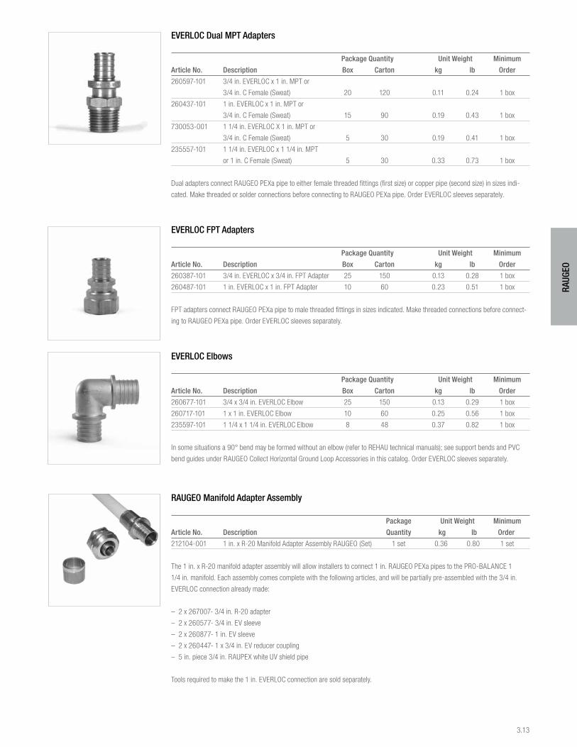
3.13
RAUG
EO
EVERLOC Dual MPT Adapters
Package Quantity Unit Weight Minimum
Article No. Description Box Carton kg lb Order
260597-101 3/4 in. EVERLOC x 1 in. MPT or
3/4 in. C Female (Sweat) 20 120 0.11 0.24 1 box
260437-101 1 in. EVERLOC x 1 in. MPT or
3/4 in. C Female (Sweat) 15 90 0.19 0.43 1 box
730053-001 1 1/4 in. EVERLOC X 1 in. MPT or
3/4 in. C Female (Sweat) 5 30 0.19 0.41 1 box
235557-101 1 1/4 in. EVERLOC x 1 1/4 in. MPT
or 1 in. C Female (Sweat) 5 30 0.33 0.73 1 box
Dual adapters connect RAUGEO PEXa pipe to either female threaded fittings (first size) or copper pipe (second size) in sizes indi-
cated. Make threaded or solder connections before connecting to RAUGEO PEXa pipe. Order EVERLOC sleeves separately.
EVERLOC FPT Adapters
Package Quantity Unit Weight Minimum
Article No. Description Box Carton kg lb Order
260387-101 3/4 in. EVERLOC x 3/4 in. FPT Adapter 25 150 0.13 0.28 1 box
260487-101 1 in. EVERLOC x 1 in. FPT Adapter 10 60 0.23 0.51 1 box
FPT adapters connect RAUGEO PEXa pipe to male threaded fittings in sizes indicated. Make threaded connections before connect-
ing to RAUGEO PEXa pipe. Order EVERLOC sleeves separately.
EVERLOC Elbows
Package Quantity Unit Weight Minimum
Article No. Description Box Carton kg lb Order
260677-101 3/4 x 3/4 in. EVERLOC Elbow 25 150 0.13 0.29 1 box
260717-101 1 x 1 in. EVERLOC Elbow 10 60 0.25 0.56 1 box
235597-101 1 1/4 x 1 1/4 in. EVERLOC Elbow 8 48 0.37 0.82 1 box
In some situations a 90° bend may be formed without an elbow (refer to REHAU technical manuals); see support bends and PVC
bend guides under RAUGEO Collect Horizontal Ground Loop Accessories in this catalog. Order EVERLOC sleeves separately.
RAUGEO Manifold Adapter Assembly
Package Unit Weight Minimum
Article No. Description Quantity kg lb Order
212104-001 1 in. x R-20 Manifold Adapter Assembly RAUGEO (Set) 1 set 0.36 0.80 1 set
The 1 in. x R-20 manifold adapter assembly will allow installers to connect 1 in. RAUGEO PEXa pipes to the PRO-BALANCE 1
1/4 in. manifold. Each assembly comes complete with the following articles, and will be partially pre-assembled with the 3/4 in.
EVERLOC connection already made:
– 2 x 267007- 3/4 in. R-20 adapter
– 2 x 260577- 3/4 in. EV sleeve
– 2 x 260877- 1 in. EV sleeve
– 2 x 260447- 1 x 3/4 in. EV reducer coupling
– 5 in. piece 3/4 in. RAUPEX white UV shield pipe
Tools required to make the 1 in. EVERLOC connection are sold separately.
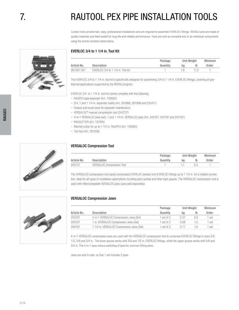
3.14
RAUG
EO
Custom tools provide fast, easy, professional installations and are required to assemble EVERLOC fittings. REHAU tools are made of
quality materials and field-tested for long life and reliable performance. Tools are sold as complete kits or as individual components
using the article numbers listed below.
EVERLOC 3/4 to 1 1/4 in. Tool Kit
Package Unit Weight Minimum
Article No. Description Quantity kg lb Order
281391-001 EVERLOC 3/4 to 1 1/4 in. Tool kit 1 7.8 17.2 1
The EVERLOC 3/4 to 1 1/4 in. tool kit is specifically designed for assembling 3/4 to 1 1/4 in. EVERLOC fittings, covering all geo-
thermal applications supported by the REHAU program.
EVERLOC 3/4 to 1 1/4 in. tool kit comes complete with the following:
– RAUPEX pipe expander (Art. 139592)
– 3/4, 1 and 1 1/4 in. expander heads (Art. 261886, 261896 and 235417)
– Grease and brush pack for expander maintenance
– VERSALOC® manual compression tool (243737)
– 4-in-1 VERSALOC jaws (set), 1 and 1 1/4 in. VERSALOC jaws (Art. 243767, 243787 and 243797)
– RAUCUTTER (Art. 137495)
– Ratchet cutter for up to 1 1/2 in. RAUPEX (Art. 138062)
– Tool box (Art. 261206)
VERSALOC Compression Tool
Package Unit Weight Minimum
Article No. Description Quantity kg lb Order
243737 VERSALOC Compression Tool 1 1.1 2.4 1
The VERSALOC compression tool easily compresses EVERLOC sleeves onto EVERLOC fittings up to 1 1/4 in. for a reliable connec-
tion. Ideal for all types of installation applications including joist cavities and other tight spaces. The VERSALOC compression tool is
used with interchangeable VERSALOC jaws (jaws sold separately).
VERSALOC Compression Jaws
Package Unit Weight Minimum
Article No. Description Quantity kg lb Order
243767 4-in-1 VERSALOC Compression Jaws (Set) 1 set of 2 0.37 0.8 1 set
243787 1 in. VERSALOC Compression Jaws (Set) 1 set of 2 0.68 1.5 1 set
243797 1 1/4 in. VERSALOC Compression Jaws (Set) 1 set of 2 0.77 1.6 1 set
4-in-1 VERSALOC compression jaws are used with the VERSALOC compression tool to compress EVERLOC fittings in sizes 3/8,
1/2, 5/8 and 3/4 in.. The lower groove works with 3/8 and 1/2 in. EVERLOC fittings, while the upper groove works with 5/8 and
3/4 in. The 4-in-1 jaws reduce switching of jaws for common fitting sizes.
Jaws are sold in sets, so that 1 set includes 2 jaws.
7. RAUtOOl pEx pipE instAllAtiOn tOOls
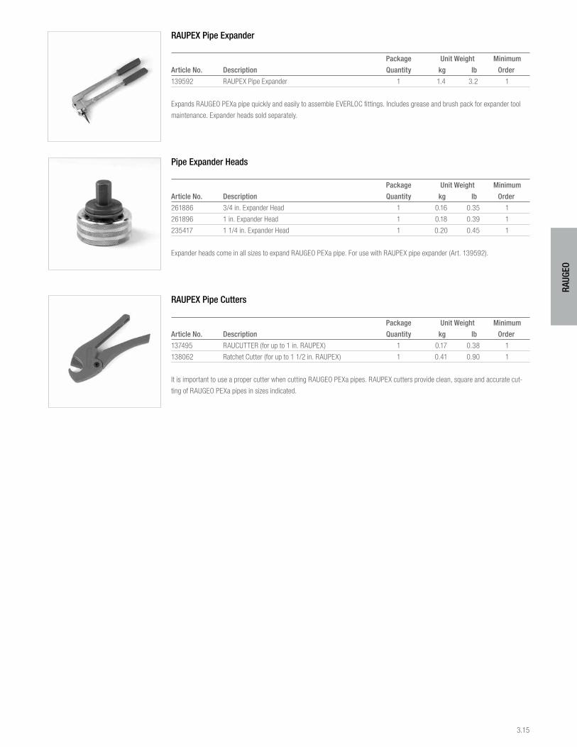
3.15
RAUG
EO
RAUPEX Pipe Expander
Package Unit Weight Minimum
Article No. Description Quantity kg lb Order
139592 RAUPEX Pipe Expander 1 1.4 3.2 1
Expands RAUGEO PEXa pipe quickly and easily to assemble EVERLOC fittings. Includes grease and brush pack for expander tool
maintenance. Expander heads sold separately.
Pipe Expander Heads
Package Unit Weight Minimum
Article No. Description Quantity kg lb Order
261886 3/4 in. Expander Head 1 0.16 0.35 1
261896 1 in. Expander Head 1 0.18 0.39 1
235417 1 1/4 in. Expander Head 1 0.20 0.45 1
Expander heads come in all sizes to expand RAUGEO PEXa pipe. For use with RAUPEX pipe expander (Art. 139592).
RAUPEX Pipe Cutters
Package Unit Weight Minimum
Article No. Description Quantity kg lb Order
137495 RAUCUTTER (for up to 1 in. RAUPEX) 1 0.17 0.38 1
138062 Ratchet Cutter (for up to 1 1/2 in. RAUPEX) 1 0.41 0.90 1
It is important to use a proper cutter when cutting RAUGEO PEXa pipes. RAUPEX cutters provide clean, square and accurate cut-
ting of RAUGEO PEXa pipes in sizes indicated.

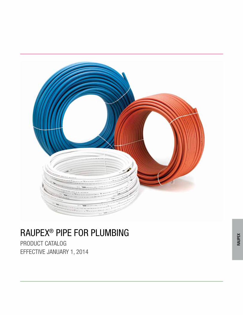
RAUPEX® PiPE foR PlUmbingPRodUct cAtAlogEffEctivE jAnUARY 1, 2014
RAUP
EX
4.2
RAUP
EX
1. RAUPEX® UV Shield Pipe . . . . . . . . . . . . . . . . . . . . . . . . . . . 4.3
2. Installation Accessories. . . . . . . . . . . . . . . . . . . . . . . . . . . . 4.9
3. Installation Tools . . . . . . . . . . . . . . . . . . . . . . . . . . . . . . . . 4.12
tAblE of contEnts
For updates to this publication and the most current technical instructions, safety information and manufacturer’s recommendations, visit na.rehau.com/resourcecenter
pw
4.3
RAUP
EX
RAUPEX UV shield pipe is manufactured using REHAU’s high-pressure peroxide method for crosslinked polyethylene (PEXa).
RAUPEX UV shield pipe has a co-extruded PE shield that protects the pipe against ultraviolet light (sunlight) for an extended time.
All RAUPEX UV shield pipe meets or exceeds the requirements of ASTM F876, CSA B137.5 and PPI TR-3 and is certified to NSF
Standards 14/61. RAUPEX UV shield pipe is manufactured by REHAU in a plant using a quality management system that is certified
to ISO 9001.
RAUPEX UV shield pipe is compatible with compression-sleeve fittings certified to ASTM F2080 and CSA B137.5, crimp ring fit-
tings certified to ASTM F1807 or F2159, and RAUPEX compression nut fittings.
RAUPEX RED UV SHIELD PIPE
3/8 in. RAUPEX Red UV Shield Pipe
Package Unit Weight Minimum
Article No. Description Quantity kg lb Order
235331-502+ 3/8 in. RAUPEX Red UV Shield Pipe 1 pallet/
500 ft coil (152.4 m) 500 ft 10.5 23.1 14,000 ft
235331-002+ 3/8 in. RAUPEX Red UV Shield Pipe 1 pallet/
1000 ft coil (304.8 m) 1000 ft 21.0 46.2 9,000 ft
+ This item is not stocked. Lead times may vary.
Average 3/8 in. pipe capacity is 0.0050 US gallons per foot (0.0624 l/m).
1/2 in. RAUPEX Red UV Shield Pipe
Package Unit Weight Minimum
Article No. Description Quantity kg lb Order
235351-102 1/2 in. RAUPEX Red UV Shield Pipe
100 ft coil (30.5 m) 100 ft 2.6 5.8 1 coil
235351-302 1/2 in. RAUPEX Red UV Shield Pipe
300 ft coil (91.4 m) 300 ft 7.8 17.2 1 coil
235351-502 1/2 in. RAUPEX Red UV Shield Pipe
500 ft coil (152.4 m) 500 ft 13.1 28.9 1 coil
235351-002 1/2 in. RAUPEX Red UV Shield Pipe
1000 ft coil (304.8 m) 1000 ft 26.3 57.9 1 coil
235351-152 1/2 in. RAUPEX Red UV Shield Pipe 5 (100 ft)
500 ft (152.4 m) coils/box 13.1 28.9 1 box
235351-352 1/2 in. RAUPEX Red UV Shield Pipe 5 (300 ft)
1500 ft (457.2 m) coils/box 41.1 90.5 1 box
Average 1/2 in. pipe capacity is 0.0098 US gallons per foot (0.1222 l/m).
1. RAUPEX Uv shiEld PiPE
4.4
RAUP
EX
3/4 in. RAUPEX Red UV Shield Pipe
Package Unit Weight Minimum
Article No. Description Quantity kg lb Order
235371-102 3/4 in. RAUPEX Red UV Shield Pipe,
100 ft coil (30.5 m) 100 ft 4.9 10.9 1 coil
235371-302 3/4 in. RAUPEX Red UV Shield Pipe,
300 ft coil (91.4 m) 300 ft 14.7 32.3 1 coil
235371-502 3/4 in. RAUPEX Red UV Shield Pipe,
500 ft coil (152.4 m) 500 ft 24.6 54.3 1 coil
235371-152 3/4 in. RAUPEX Red UV Shield Pipe, 5 (100 ft)
500 ft (152.4 m) coils/box 29.5 65 1 box
Average 3/4 in. pipe capacity is 0.0189 US gallons per foot (0.2356 l/m).
1 in. RAUPEX Red UV Shield Pipe
Package Unit Weight Minimum
Article No. Description Quantity kg lb Order
235381-102 1 in. RAUPEX Red UV Shield Pipe,
100 ft coil (30.5 m) 100 ft 7.9 17.5 1 coil
235381-302 1 in. RAUPEX Red UV Shield Pipe,
300 ft coil (91.4 m) 300 ft 23.8 52.4 1 coil
235381-502 1 in. RAUPEX Red UV Shield Pipe,
500 ft coil (152.4 m) 500 ft 39.7 87.5 1 coil
Average 1 in. pipe capacity is 0.0316 US gallons per foot (0.3939 l/m).
RAUPEX Red UV Shield Pipe 20 ft Straight Lengths
Package Quantity Unit Weight Minimum
Article No. Description Bag kg lb Order
235351-022 1/2 in. RAUPEX Red UV Shield Pipe,
20 ft (6.1 m) 50 pcs (1000 ft) 0.5 1.2 1 bag
235371-022 3/4 in. RAUPEX Red UV Shield Pipe,
20 ft (6.1 m) 25 pcs (500 ft) 1.0 2.2 1 bag
235381-022 1 in. RAUPEX Red UV Shield Pipe,
20 ft (6.1 m) 25 pcs (500 ft) 1.6 3.5 1 bag
Same average capacities as RAUPEX UV Shield Pipe sold in coils. Straight lengths are packaged in a single outer bag.
RAUPEX BLUE UV SHIELD PIPE
3/8 in. RAUPEX Blue UV Shield Pipe
Package Unit Weight Minimum
Article No. Description Quantity kg lb Order
235331-501+ 3/8 in. RAUPEX Blue UV Shield Pipe 1 pallet/
500 ft coil (152.4 m) 500 ft 10.5 23.1 14,000 ft
235331-001+ 3/8 in. RAUPEX Blue UV Shield Pipe 1 pallet
1000 ft coil (304.8 m) 1000 ft 21.0 46.2 9,000 ft
+ This item is not stocked. Lead times may vary.
Average 3/8 in. pipe capacity is 0.0050 US gallons per foot (0.0624 l/m).
4.5
RAUP
EX
1/2 in. RAUPEX Blue UV Shield Pipe
Package Unit Weight Minimum
Article No. Description Quantity kg lb Order
235351-101 1/2 in. RAUPEX Blue UV Shield Pipe
100 ft coil (30.5 m) 100 ft 2.6 5.8 1 coil
235351-301 1/2 in. RAUPEX Blue UV Shield Pipe
300 ft coil (91.4 m) 300 ft 7.8 17.2 1 coil
235351-501 1/2 in. RAUPEX Blue UV Shield Pipe
500 ft coil (152.4 m) 500 ft 13.1 28.9 1 coil
235351-001 1/2 in. RAUPEX Blue UV Shield Pipe
1000 ft coil (304.8 m) 1000 ft 26.3 57.9 1 coil
235351-151 1/2 in. RAUPEX Blue UV Shield Pipe 5 (100 ft)
500 ft (152.4 m) coils/box 13.1 28.9 1 box
235351-351 1/2 in. RAUPEX Blue UV Shield Pipe 5 (300 ft)
1500 ft (457.2 m) coils/box 41.1 90.5 1 box
Average 1/2 in. pipe capacity is 0.0098 US gallons per foot (0.1222 l/m).
3/4 in. RAUPEX Blue UV Shield Pipe
Package Unit Weight Minimum
Article No. Description Quantity kg lb Order
235371-101 3/4 in. RAUPEX Blue UV Shield Pipe,
100 ft coil (30.5 m) 100 ft 4.9 10.9 1 coil
235371-301 3/4 in. RAUPEX Blue UV Shield Pipe,
300 ft coil ( 91.4 m) 300 ft 14.7 32.3 1 coil
235371-501 3/4 in. RAUPEX Blue UV Shield Pipe,
500 ft coil (152.4 m) 500 ft 24.6 54.3 1 coil
235371-151 3/4 in. RAUPEX Blue UV Shield Pipe, 5 (100 ft)
500 ft (152.4 m) coils/box 24.6 54.3 1 box
Average 3/4 in. pipe capacity is 0.0189 US gallons per foot (0.2356 l/m).
1 in. RAUPEX Blue UV Shield Pipe
Package Unit Weight Minimum
Article No. Description Quantity kg lb Order
235381-101 1 in. RAUPEX Blue UV Shield Pipe,
100 ft coil (30.5 m) 100 ft 7.9 17.5 1 coil
235381-301 1 in. RAUPEX Blue UV Shield Pipe,
300 ft coil (91.4 m) 300 ft 23.8 52.4 1 coil
235381-501 1 in. RAUPEX Blue UV Shield Pipe,
500 ft coil (152.4 m) 500 ft 39.7 87.5 1 coil
Average 1 in. pipe capacity is 0.0316 US gallons per foot (0.3939 l/m).
4.6
RAUP
EX
RAUPEX Blue UV Shield Pipe 20 ft Straight Lengths
Package Quantity Unit Weight Minimum
Article No. Description Bag kg lb Order
235351-021 1/2 in. RAUPEX Blue UV Shield Pipe,
20 ft (6.1 m) 50 pcs (1000 ft) 0.50 1.2 1 bag
235371-021 3/4 in. RAUPEX Blue UV Shield Pipe,
20 ft (6.1 m) 25 pcs (500 ft) 1.0 2.2 1 bag
235381-021 1 in. RAUPEX Blue UV Shield Pipe,
20 ft (6.1 m) 25 pcs (500 ft) 1.6 3.5 1 bag
Same average capacities as RAUPEX UV shield pipe sold in coils. Straight lengths are packaged in a single outer bag.
RAUPEX WHITE UV SHIELD PIPE
1/2 in. RAUPEX White UV Shield Pipe
Package Unit Weight Minimum
Article No. Description Quantity kg lb Order
235351-113 1/2 in. RAUPEX White UV Shield Pipe
100 ft coil (30.5 m) 100 ft 2.6 5.8 1 coil
235351-313 1/2 in. RAUPEX White UV Shield Pipe
300 ft coil (91.4 m) 300 ft 7.8 17.2 1 coil
235351-513 1/2 in. RAUPEX White UV Shield Pipe
500 ft coil (152.4 m) 500 ft 13.1 28.9 1 coil
235351-013 1/2 in. RAUPEX White UV Shield Pipe
1000 ft coil (304.8 m) 1000 ft 26.3 57.9 1 coil
235351-153 1/2 in. RAUPEX White UV Shield Pipe, 5 (100 ft)
500 ft (152.4 m) coils/box 13.1 28.9 1 box
235351-353 1/2 in. RAUPEX White UV Shield Pipe, 5 (300 ft)
1500 ft (457.2 m) coils/box 41.1 90.5 1 box
Average 1/2 in. pipe capacity is 0.0098 US gallons per foot (0.1222 l/m).
3/4 in. RAUPEX White UV Shield Pipe
Package Unit Weight Minimum
Article No. Description Quantity kg lb Order
235371-113 3/4 in. RAUPEX White UV Shield Pipe,
100 ft coil (30.5 m) 100 ft 4.9 10.9 1 coil
235371-313 3/4 in. RAUPEX White UV Shield Pipe,
300 ft coil (91.4 m) 300 ft 14.7 32.3 1 coil
235371-513 3/4 in. RAUPEX White UV Shield Pipe,
500 ft coil (152.4 m) 500 ft 24.6 54.3 1 coil
235371-013 3/4 in. RAUPEX White UV Shield Pipe,
1000 ft coil (304.8 m) 1000 ft 48.9 108.0 1 coil
235371-153 3/4 in. RAUPEX White UV Shield Pipe, 5 (100 ft)
500 ft coil (152.4 m) coils/box 24.6 54.3 1 box
Average 3/4 in. pipe capacity is 0.0189 US gallons per foot (0.2356 l/m).
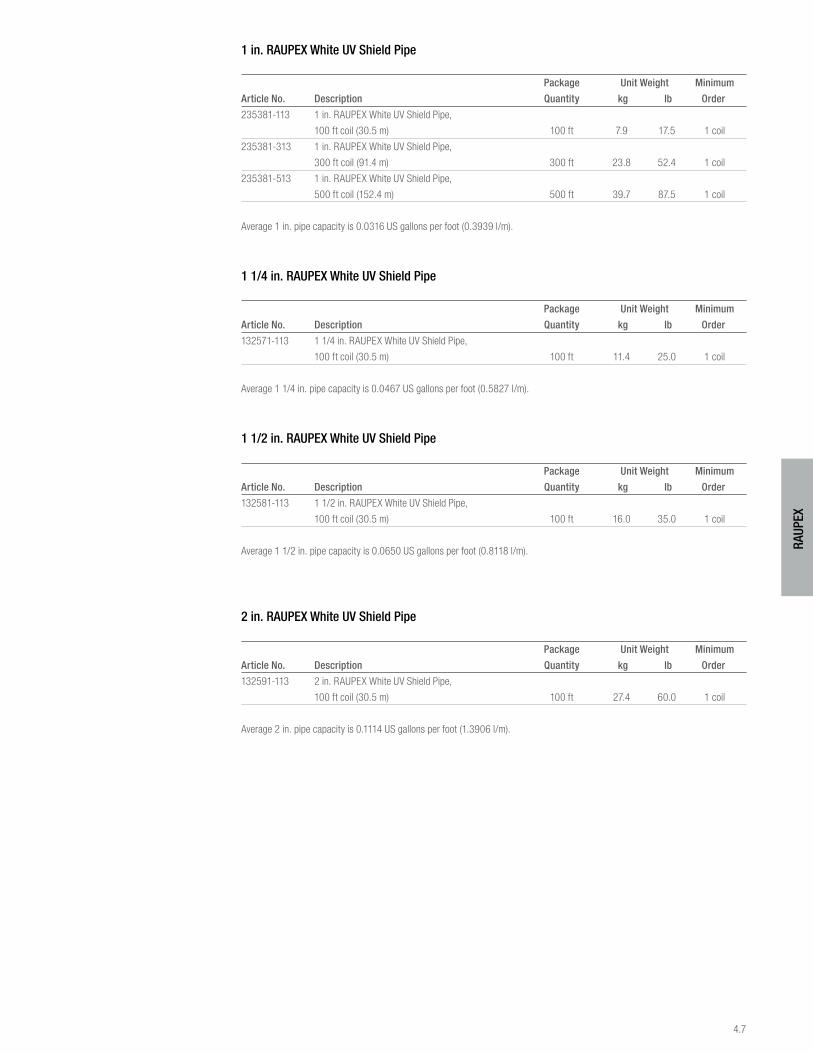
4.7
RAUP
EX
1 in. RAUPEX White UV Shield Pipe
Package Unit Weight Minimum
Article No. Description Quantity kg lb Order
235381-113 1 in. RAUPEX White UV Shield Pipe,
100 ft coil (30.5 m) 100 ft 7.9 17.5 1 coil
235381-313 1 in. RAUPEX White UV Shield Pipe,
300 ft coil (91.4 m) 300 ft 23.8 52.4 1 coil
235381-513 1 in. RAUPEX White UV Shield Pipe,
500 ft coil (152.4 m) 500 ft 39.7 87.5 1 coil
Average 1 in. pipe capacity is 0.0316 US gallons per foot (0.3939 l/m).
1 1/4 in. RAUPEX White UV Shield Pipe
Package Unit Weight Minimum
Article No. Description Quantity kg lb Order
132571-113 1 1/4 in. RAUPEX White UV Shield Pipe,
100 ft coil (30.5 m) 100 ft 11.4 25.0 1 coil
Average 1 1/4 in. pipe capacity is 0.0467 US gallons per foot (0.5827 l/m).
1 1/2 in. RAUPEX White UV Shield Pipe
Package Unit Weight Minimum
Article No. Description Quantity kg lb Order
132581-113 1 1/2 in. RAUPEX White UV Shield Pipe,
100 ft coil (30.5 m) 100 ft 16.0 35.0 1 coil
Average 1 1/2 in. pipe capacity is 0.0650 US gallons per foot (0.8118 l/m).
2 in. RAUPEX White UV Shield Pipe
Package Unit Weight Minimum
Article No. Description Quantity kg lb Order
132591-113 2 in. RAUPEX White UV Shield Pipe,
100 ft coil (30.5 m) 100 ft 27.4 60.0 1 coil
Average 2 in. pipe capacity is 0.1114 US gallons per foot (1.3906 l/m).
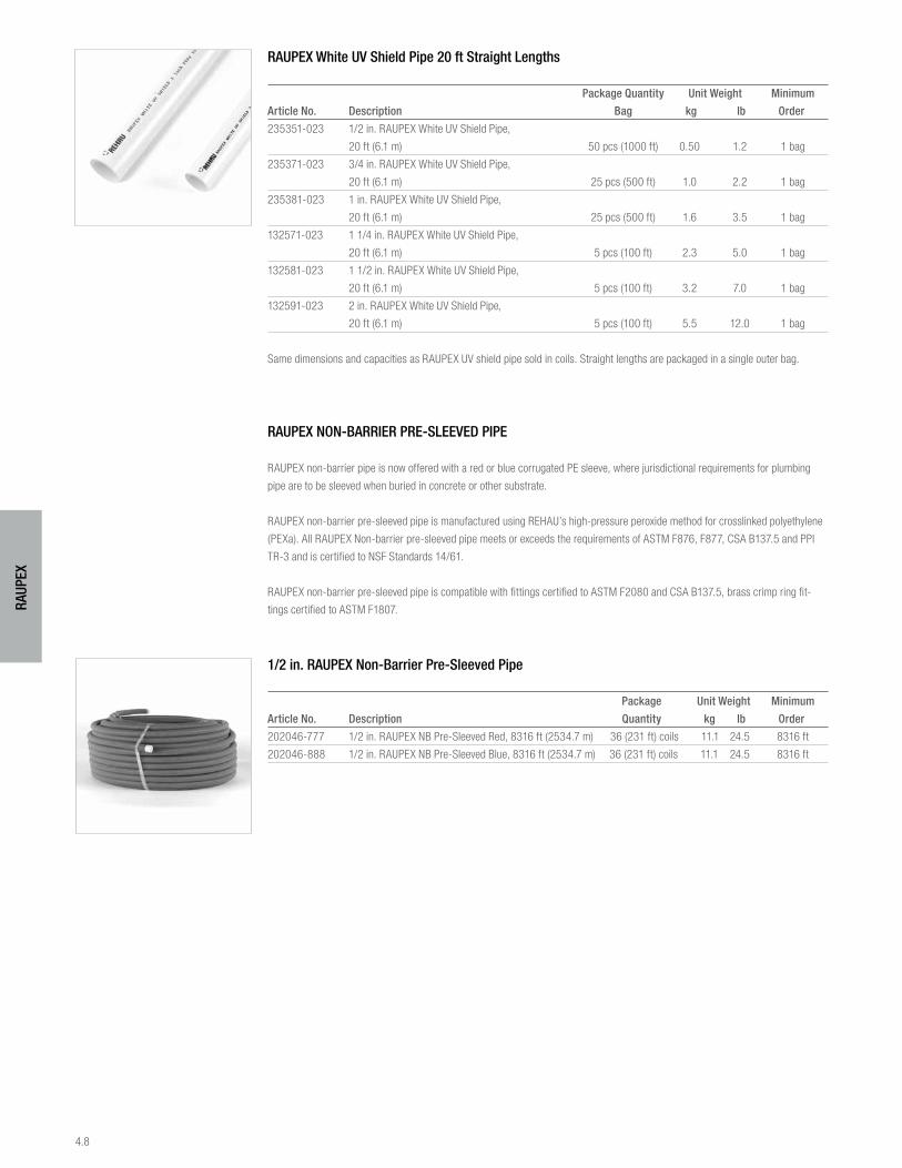
4.8
RAUP
EX
RAUPEX White UV Shield Pipe 20 ft Straight Lengths
Package Quantity Unit Weight Minimum
Article No. Description Bag kg lb Order
235351-023 1/2 in. RAUPEX White UV Shield Pipe,
20 ft (6.1 m) 50 pcs (1000 ft) 0.50 1.2 1 bag
235371-023 3/4 in. RAUPEX White UV Shield Pipe,
20 ft (6.1 m) 25 pcs (500 ft) 1.0 2.2 1 bag
235381-023 1 in. RAUPEX White UV Shield Pipe,
20 ft (6.1 m) 25 pcs (500 ft) 1.6 3.5 1 bag
132571-023 1 1/4 in. RAUPEX White UV Shield Pipe,
20 ft (6.1 m) 5 pcs (100 ft) 2.3 5.0 1 bag
132581-023 1 1/2 in. RAUPEX White UV Shield Pipe,
20 ft (6.1 m) 5 pcs (100 ft) 3.2 7.0 1 bag
132591-023 2 in. RAUPEX White UV Shield Pipe,
20 ft (6.1 m) 5 pcs (100 ft) 5.5 12.0 1 bag
Same dimensions and capacities as RAUPEX UV shield pipe sold in coils. Straight lengths are packaged in a single outer bag.
RAUPEX NON-BARRIER PRE-SLEEVED PIPE
RAUPEX non-barrier pipe is now offered with a red or blue corrugated PE sleeve, where jurisdictional requirements for plumbing
pipe are to be sleeved when buried in concrete or other substrate.
RAUPEX non-barrier pre-sleeved pipe is manufactured using REHAU’s high-pressure peroxide method for crosslinked polyethylene
(PEXa). All RAUPEX Non-barrier pre-sleeved pipe meets or exceeds the requirements of ASTM F876, F877, CSA B137.5 and PPI
TR-3 and is certified to NSF Standards 14/61.
RAUPEX non-barrier pre-sleeved pipe is compatible with fittings certified to ASTM F2080 and CSA B137.5, brass crimp ring fit-
tings certified to ASTM F1807.
1/2 in. RAUPEX Non-Barrier Pre-Sleeved Pipe
Package Unit Weight Minimum
Article No. Description Quantity kg lb Order
202046-777 1/2 in. RAUPEX NB Pre-Sleeved Red, 8316 ft (2534.7 m) 36 (231 ft) coils 11.1 24.5 8316 ft
202046-888 1/2 in. RAUPEX NB Pre-Sleeved Blue, 8316 ft (2534.7 m) 36 (231 ft) coils 11.1 24.5 8316 ft
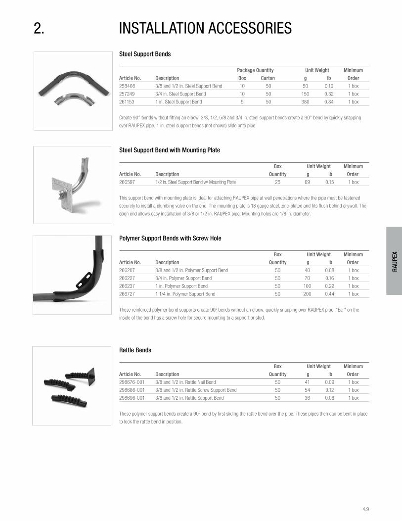
4.9
RAUP
EX
Steel Support Bends
Package Quantity Unit Weight Minimum
Article No. Description Box Carton g lb Order
258408 3/8 and 1/2 in. Steel Support Bend 10 50 50 0.10 1 box
257249 3/4 in. Steel Support Bend 10 50 150 0.32 1 box
261153 1 in. Steel Support Bend 5 50 380 0.84 1 box
Create 90° bends without fitting an elbow. 3/8, 1/2, 5/8 and 3/4 in. steel support bends create a 90° bend by quickly snapping
over RAUPEX pipe. 1 in. steel support bends (not shown) slide onto pipe.
Steel Support Bend with Mounting Plate
Box Unit Weight Minimum
Article No. Description Quantity g lb Order
266597 1/2 in. Steel Support Bend w/ Mounting Plate 25 69 0.15 1 box
This support bend with mounting plate is ideal for attaching RAUPEX pipe at wall penetrations where the pipe must be fastened
securely to install a plumbing valve on the end. The mounting plate is 18 gauge steel, zinc-plated and fits flush behind drywall. The
open end allows easy installation of 3/8 or 1/2 in. RAUPEX pipe. Mounting holes are 1/8 in. diameter.
Polymer Support Bends with Screw Hole
Box Unit Weight Minimum
Article No. Description Quantity g lb Order
266207 3/8 and 1/2 in. Polymer Support Bend 50 40 0.08 1 box
266227 3/4 in. Polymer Support Bend 50 70 0.16 1 box
266237 1 in. Polymer Support Bend 50 100 0.22 1 box
266727 1 1/4 in. Polymer Support Bend 50 200 0.44 1 box
These reinforced polymer bend supports create 90º bends without an elbow, quickly snapping over RAUPEX pipe. "Ear" on the
inside of the bend has a screw hole for secure mounting to a support or stud.
Rattle Bends
Box Unit Weight Minimum
Article No. Description Quantity g lb Order
298676-001 3/8 and 1/2 in. Rattle Nail Bend 50 41 0.09 1 box
298686-001 3/8 and 1/2 in. Rattle Screw Support Bend 50 54 0.12 1 box
298696-001 3/8 and 1/2 in. Rattle Support Bend 50 36 0.08 1 box
These polymer support bends create a 90º bend by first sliding the rattle bend over the pipe. These pipes then can be bent in place
to lock the rattle bend in position.
2. instAllAtion AccEssoRiEs
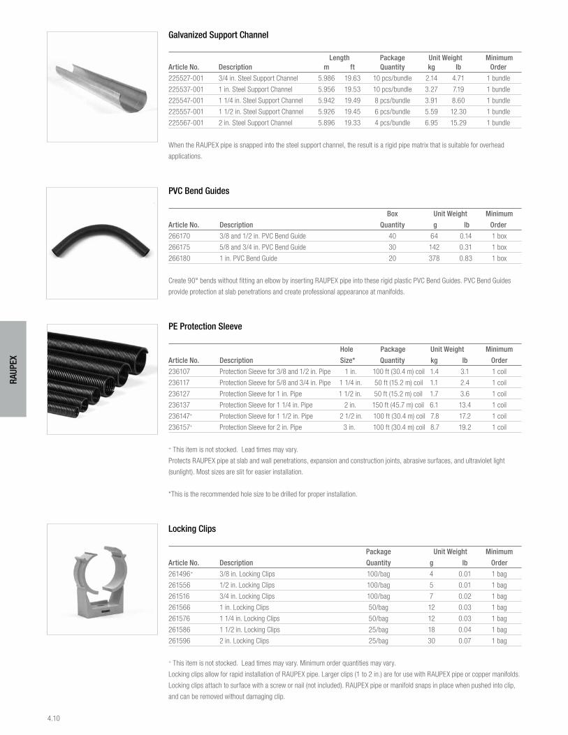
4.10
RAUP
EX
Galvanized Support Channel
Length Package Unit Weight Minimum Article No. Description m ft Quantity kg lb Order
225527-001 3/4 in. Steel Support Channel 5.986 19.63 10 pcs/bundle 2.14 4.71 1 bundle
225537-001 1 in. Steel Support Channel 5.956 19.53 10 pcs/bundle 3.27 7.19 1 bundle
225547-001 1 1/4 in. Steel Support Channel 5.942 19.49 8 pcs/bundle 3.91 8.60 1 bundle
225557-001 1 1/2 in. Steel Support Channel 5.926 19.45 6 pcs/bundle 5.59 12.30 1 bundle
225567-001 2 in. Steel Support Channel 5.896 19.33 4 pcs/bundle 6.95 15.29 1 bundle
When the RAUPEX pipe is snapped into the steel support channel, the result is a rigid pipe matrix that is suitable for overhead
applications.
PVC Bend Guides
Box Unit Weight Minimum
Article No. Description Quantity g lb Order
266170 3/8 and 1/2 in. PVC Bend Guide 40 64 0.14 1 box
266175 5/8 and 3/4 in. PVC Bend Guide 30 142 0.31 1 box
266180 1 in. PVC Bend Guide 20 378 0.83 1 box
Create 90° bends without fitting an elbow by inserting RAUPEX pipe into these rigid plastic PVC Bend Guides. PVC Bend Guides
provide protection at slab penetrations and create professional appearance at manifolds.
PE Protection Sleeve
Hole Package Unit Weight Minimum
Article No. Description Size* Quantity kg lb Order
236107 Protection Sleeve for 3/8 and 1/2 in. Pipe 1 in. 100 ft (30.4 m) coil 1.4 3.1 1 coil
236117 Protection Sleeve for 5/8 and 3/4 in. Pipe 1 1/4 in. 50 ft (15.2 m) coil 1.1 2.4 1 coil
236127 Protection Sleeve for 1 in. Pipe 1 1/2 in. 50 ft (15.2 m) coil 1.7 3.6 1 coil
236137 Protection Sleeve for 1 1/4 in. Pipe 2 in. 150 ft (45.7 m) coil 6.1 13.4 1 coil
236147+ Protection Sleeve for 1 1/2 in. Pipe 2 1/2 in. 100 ft (30.4 m) coil 7.8 17.2 1 coil
236157+ Protection Sleeve for 2 in. Pipe 3 in. 100 ft (30.4 m) coil 8.7 19.2 1 coil
+ This item is not stocked. Lead times may vary.
Protects RAUPEX pipe at slab and wall penetrations, expansion and construction joints, abrasive surfaces, and ultraviolet light
(sunlight). Most sizes are slit for easier installation.
*This is the recommended hole size to be drilled for proper installation.
Locking Clips
Package Unit Weight Minimum
Article No. Description Quantity g lb Order
261496+ 3/8 in. Locking Clips 100/bag 4 0.01 1 bag
261556 1/2 in. Locking Clips 100/bag 5 0.01 1 bag
261516 3/4 in. Locking Clips 100/bag 7 0.02 1 bag
261566 1 in. Locking Clips 50/bag 12 0.03 1 bag
261576 1 1/4 in. Locking Clips 50/bag 12 0.03 1 bag
261586 1 1/2 in. Locking Clips 25/bag 18 0.04 1 bag
261596 2 in. Locking Clips 25/bag 30 0.07 1 bag
+ This item is not stocked. Lead times may vary. Minimum order quantities may vary.
Locking clips allow for rapid installation of RAUPEX pipe. Larger clips (1 to 2 in.) are for use with RAUPEX pipe or copper manifolds.
Locking clips attach to surface with a screw or nail (not included). RAUPEX pipe or manifold snaps in place when pushed into clip,
and can be removed without damaging clip.
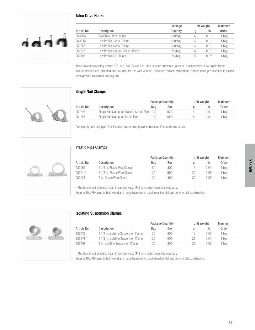
4.11
RAUP
EX
Talon Drive Hooks
Package Unit Weight Minimum
Article No. Description Quantity g lb Order
260866 Twin Talon Drive Hooks 100/bag 6 0.01 1 bag
260846 Low Profile 3/8 in. Talons 100/bag 4 0.01 1 bag
261766 Low Profile 1/2 in. Talons 100/bag 4 0.01 1 bag
261776 Low Profile 5/8 and 3/4 in. Talons 50/bag 6 0.01 1 bag
261806 Low Profile 1 in. Talons 50/bag 10 0.02 1 bag
Talon drive hooks safely secure 3/8, 1/2, 5/8, 3/4 or 1 in. pipe to wood subfloors, joists or in joist cavities. Low profile talons
secure pipe in sizes indicated and are ideal for use with wooden "sleeper" radiant installations. Barbed nails, pre-installed in plastic
talon prevent nails from backing out.
Single Nail Clamps
Package Quantity Unit Weight Minimum
Article No. Description Bag Box g lb Order
261746 Single Nail Clamp for 3/8 and 1/2 in. Pipe 100 1500 4 0.01 1 bag
261756 Single Nail Clamp for 3/4 in. Pipe 100 1000 5 0.01 1 bag
Completely encircles pipe. Pre-installed barbed nail prevents backout. Fast and easy to use.
Plastic Pipe Clamps
Package Quantity Unit Weight Minimum
Article No. Description Bag Box g lb Order
282401 1 1/4 in. Plastic Pipe Clamp 50 800 16 0.04 1 bag
282411+ 1 1/2 in. Plastic Pipe Clamp 25 600 20 0.05 1 bag
282421 2 in. Plastic Pipe Clamp 25 300 32 0.07 1 bag
+ This item is not stocked. Lead times may vary. Minimum order quantities may vary.
Secures RAUPEX pipe to both wood and metal framework. Used in residential and commercial construction.
Isolating Suspension Clamps
Package Quantity Unit Weight Minimum
Article No. Description Bag Box g lb Order
282431+ 1 1/4 in. Isolating Suspension Clamp 50 800 15 0.03 1 bag
282441 1 1/2 in. Isolating Suspension Clamp 25 600 28 0.04 1 bag
282451 2 in. Isolating Suspension Clamp 25 300 23 0.05 1 bag
+ This item is not stocked. Lead times may vary. Minimum order quantities may vary.
Secures RAUPEX pipe to both wood and metal framework. Used in residential and commercial construction.
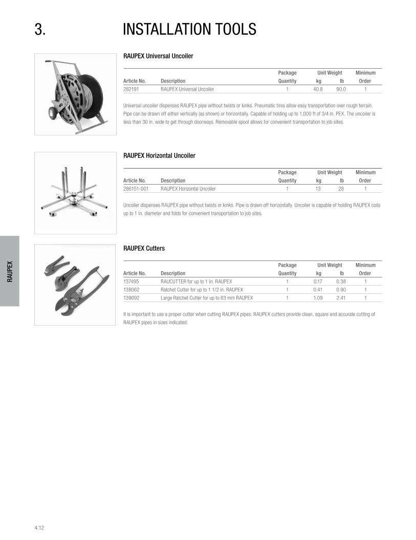
4.12
RAUP
EX
3. instAllAtion toolsRAUPEX Universal Uncoiler
Package Unit Weight Minimum
Article No. Description Quantity kg lb Order
282191 RAUPEX Universal Uncoiler 1 40.8 90.0 1
Universal uncoiler dispenses RAUPEX pipe without twists or kinks. Pneumatic tires allow easy transportation over rough terrain.
Pipe can be drawn off either vertically (as shown) or horizontally. Capable of holding up to 1,000 ft of 3/4 in. PEX. The uncoiler is
less than 30 in. wide to get through doorways. Removable spool allows for convenient transportation to job sites.
RAUPEX Horizontal Uncoiler
Package Unit Weight Minimum
Article No. Description Quantity kg lb Order
286151-001 RAUPEX Horizontal Uncoiler 1 13 28 1
Uncoiler dispenses RAUPEX pipe without twists or kinks. Pipe is drawn off horizontally. Uncoiler is capable of holding RAUPEX coils
up to 1 in. diameter and folds for convenient transportation to job sites.
RAUPEX Cutters
Package Unit Weight Minimum
Article No. Description Quantity kg lb Order
137495 RAUCUTTER for up to 1 in. RAUPEX 1 0.17 0.38 1
138062 Ratchet Cutter for up to 1 1/2 in. RAUPEX 1 0.41 0.90 1
139092 Large Ratchet Cutter for up to 63 mm RAUPEX 1 1.09 2.41 1
It is important to use a proper cutter when cutting RAUPEX pipes. RAUPEX cutters provide clean, square and accurate cutting of
RAUPEX pipes in sizes indicated.
www.rehau.com [email protected]
For updates to this publication, visit na.rehau.com/resourcecenter The information contained herein is believed to be reliable, but no representations, guarantees or warranties of any kind are made as to its accuracy, suitability for particular applications or the results to be obtained therefrom. Before using, the user will determine suitability of the information for user’s intended use and shall assume all risk and liability in connection therewith. © 2014 REHAU Printed in Canada
WarrantyREHAU stands behind our products with a 25-year limited warranty on PEXa pipe and EVERLOC® fittings. www.na.rehau.com/warranties
Return PolicyEach return will be reviewed individually. No material may be returned without our written permission and return authorization number. Only catalogued and resalable items may be returned. The minimum return value will be $100. Product and packaging has to be in resalable condi-tion, all products returned to the distribution center are subject to quality inspection. Materials have to be in original clean and closed packaging (where applicable), boxes must have original labels, customer label must be removed prior to return. Any material which is authorized to be returned will be subject to a minimum twenty-five (25) percent restocking fee.
Sales Offices (Toll-free) Canada Maritimes (800) 565-7342 · Québec (800) 361-0830 · Ontario (800) 561-9609 · Western Canada (800) 668-1173 United States Eastern US (800) 297-6371 · Western US (800) 944-1011 Mexico Northern Mexico (818) 121-0130 · Central and Southern Mexico (800) 917-3428 Central America Panama (507) 830-5257
855.312 01.2014