sv1404-2e-a increasing the safety level with the mr-d30
TRANSCRIPT

Increasing the Safety Level with the MR-D30 Functional Safety Unit
January 2015
New Product ReleaseSV1404-2E-A
Functional safety unit MR-D30
Servo amplifierMR-J4-10B-RJ
Functional safety unitMR-D30
Servo motor with functional safetyHG-JR703W0C
Servo motors with functional safety HG-KR_W0C/HG-SR_W0C/HG-JR_W0C
Safety is the top priority in today's automation industry.Mitsubishi's new servo motors with functional safety support safety observation functions (STO/SS1/SS2/SOS/SBC/SLS/SSM) which are compliant with Category 4 PL e, SIL 3.MR-D30 is now compatible with both MR-J4-B-RJ and MR-J4-A-RJ, allowing to configure your system more flexible.
● With the servo motors with functional safety, safety observation functions of SS2, SOS, SLS, and SSM compliant to Category 4 PL e, SIL 3 are achievable.
● In addition to MR-J4-B-RJ, MR-D30 functional safety unit is now compatible with MR-J4-A-RJ.● SOS and SS2 are achievable in addition to STO, SS1, SBC, SLS, and SSM.● A combination with Motion controller (Q17nDSCPU) enables safety communication through SSCNET III/H and
reduced wirings.
NEW
NEW
NEW
General-Purpose AC Servo MELSERVO-J4 SeriesFunctional Safety Unit MR-D30Servo Motors with Functional Safety HG-KR_W0C/HG-SR_W0C/HG-JR_W0C

1
Safety levelSafety observation function
Category 3 PL d, SIL 2STO
MR-J4 seriesMR-J4 series
Safety observationfunction as standard
specificationCategory 3 PL d, SIL 2STO/SS1
MR-J3-D05 +MR-J4 seriesMR-J3-D05 +MR-J4 series
Achieve STO/SS1with MR-J3-D05 Category 3 PL d, SIL 2
STO/SS1/SBC/SLS/SSM/SS2/SOS
Motion controllerQ17nDSCPUMotion controllerQ17nDSCPU
Expand safetyobservation functionwith Motion controller
Category 4 PL e, SIL 3STO/SS1/SBCSLS/SSM/SS2/SOS
MR-D30 +MR-J4-B-RJMR-D30 +MR-J4-B-RJ
HG-KR_W0C/HG-SR_W0C/HG-JR_W0C
HG-KR_W0C/HG-SR_W0C/HG-JR_W0C
MR-D30 +MR-J4-A-RJMR-D30 +MR-J4-A-RJ
Increase safety levelwith MR-D30
NEW
NEW
By wiring safety input signals to MR-D30 functional safety unit, safety observation function of Category 4 PL e, SIL 3 is achieved.The safety observation function of MR-D30 is compatible with status monitor (safety output) function, in addition to the functions in the table defined as "Function of power drive system" by IEC/EN 61800-5-2.
The following safety levels are achievable. Note that achievable safety level depends on whether the safety observation function is achieved through SSCNET III/H or by connecting the safety input/output directly to the functional safety unit, and whether the servo motors with functional safety are used or not.
MR-D30 has obtained the functional safety approval of TÜV SÜD.
IEC/EN 61800-5-2:2007 function
STO (Safe torque off)
SS1 (Safe stop 1)
SS2 (Safe stop 2)
SOS (Safe operating stop)
SLS (Safely-limited speed)
SBC (Safe brake control)
SSM (Safe speed monitor)
Servo motor with functional safety
Direct wiring to functional safety unit Reduced wiring through SSCNET III/H
Servo motor
Category 4 PL e, SIL 3(STO/SS1/SS2/SOS/SLS/SBC/SSM)
Category 4 PL e, SIL 3 (STO/SS1/SBC)Category 3 PL d, SIL 2 (SLS/SSM)
Category 3 PL d, SIL 2(STO/SS1/SS2/SOS/SLS/SBC/SSM)*1
Category 3 PL d, SIL 2(STO/SS1/SLS/SBC/SSM)
*1. The servo motor with functional safety will be compatible with the reduced wiring system through SSCNET III/H in the near future.
■Safety observation function achieved by MR-D30
MR-D30 functional safety unit is compatible with MR-J4-A-RJ servo amplifier with general-purpose interface. The safety observation function with MR-D30 can be used with position control by pulse train command and speed control by analog voltage command.
Owing to the encoder with improved safety, a combination of the servo motor with functional safety and MR-D30 functional safety unit supports STO/SS1/SS2/SOS/SLS/SBC/SSM which are compliant with Category 4 PL e, SIL 3.
Compatible with Pulse Train Command Servo Motors with Functional SafetyNEW NEW
Positioning module
MR-J4-A-RJMR-D30 +
Functional safety unit can be used with pulse
train command.
HG-KR_W0C HG-SR_W0C HG-JR_W0C
Achieving Category 4 PL e, SIL 3with MR-D30
Compatible with Category 4 PL e, SIL 3 Drive Safety

2
The safety level will be increased by inputting signals directly to the functional safety unit, and the wiring will be reduced by inputting the safety signals through SSCNET III/H.
Safety observation function with a combination of Motion controller and servo amplifier
Reduced wiring with a combination of functional safety unit and Motion controller
For general-purpose pulse train command (MR-J4-A-RJ + MR-D30)
Safety signal
Servo motor
External encoder External encoder
MR-J4-B/MR-J4-B-RJ/MR-J4W2-B/MR-J4W3-B
Light curtain
Power shut-off(STO cable)
Safety switch
Servo motor
Q17nDSCPUQnUD(E)(H)CPU
Q173DSXY
MR-D30 MR-D30
Safety signalSafety signal
MR-J4-B-RJ
Light curtain Safety switch Servo motor withfunctional safety*3
Servo motor withfunctional safety*3
MR-J4-B-RJQ17nDSCPUQnUD(E)(H)CPU
Q173DSXY
Safety communication via SSCNET III/H
No external encoder is required using the servo
motor with functional safety. (Capable in the
near future)
Servo motor withfunctional safety
To other servo amplifier axes
Light curtain
Safety switch
MR-J4-A-RJMR-D30
WS0-CPU0WS0-CPU1etc.
Safety controller
Safety signal
Safety signal
Safety input/output via DI/O(STO/SS1/SS2/SOS/SBC/SLS/SSM)
Safety input/output via DI/O(STO/SS1/SS2/SOS/SBC/SLS/SSM)
Servo motor withfunctional safety
Positioning module
To other servo amplifier axes
Light curtain
Safety switch
MR-J4-B-RJMR-D30
WS0-CPU0WS0-CPU1etc.
SSCNET III/Hcompatible controller
Safety controller
Safety signal
Safety signal
Category 4 PL e, SIL 3 is achieved by inputting safety signals directly to MR-D30 functional safety unit. Because the safety observation function is operated on MR-D30 side, expansion of the safety observation function is possible without depending on controllers, offering a selection from a wide variety of controllers such as Simple Motion modules, Motion controllers, and Positioning modules. Moreover, the safety observation function is easily enabled just by setting parameters.
When MR-J4-B-RJ servo amplifier is combined with MR-D30 functional safety unit, safety signals are inputted from Q17nDSCPU Motion controller*1 through SSCNET III/H. Thus, the STO cables between the controller and the servo amplifiers for sending the power shut-off signals are not necessary anymore, greatly reducing wiring time and cost. Moreover, because the servo motor with functional safety support SS2 and SOS, no additional external encoders will be necessary to achieve SS2 and SOS in the near future*3. As the safety observation function is achieved on the MR-D30 side, cost of designing ladder program on the controller side can be reduced as well.
Compatible with Category 4 PL e, SIL 3 By Wiring to Functional Safety Unit
Reduced Wiring though SSCNET III/H
*1. The safety observation function has obtained the approval of Certification Body by the combination of Q17nDSCPU, Q173DSXY and QnUD(E)(H)CPU.
*2. SS2 and SOS will be achievable in the near future by using the servo motors with functional safety unit.
*3. The servo motor with functional safety will be compatible with the reduced wiring system through SSCNET III/H in the near future.
IEC/EN 61800-5-2:2007 function Safety level
Category 3 PL d, SIL 2
STO (Safe torque off)
SS1 (Safe stop 1)
SS2 (Safe stop 2)*2
SOS (Safe operating stop)*2
SLS (Safely-limited speed)
SBC (Safe brake control)
SSM (Safe speed monitor)
*1. SS2 and SOS are achievable by using the servo motor with functional safety unit.*2. The safety level would be Category 3 PL d, SIL 2 when the servo motor with
functional safety is not used.
IEC/EN 61800-5-2:2007 function Safety level
Category 4 PL e, SIL 3
STO (Safe torque off)
SS1 (Safe stop 1)
SS2 (Safe stop 2)*1
SOS (Safe operating stop)*1
SLS (Safely-limited speed)*2
SBC (Safe brake control)
SSM (Safe speed monitor)*2
For SSCNETIII/H command (MR-J4-B-RJ + MR-D30)
Lesswiring
NEW

3
Example of SS1 (Safe stop 1) setting window
*1. Be sure to update your MR Configurator2 to the latest version.
Safety communication
Light curtain Safety switch
For axis requiring SS1, SLS, etc.
Servo motor
MR-D30 MR-J4-B-RJ
Q17nDSCPUQnUD(E)(H)CPU
Q173DSXYExpand safety observation function as necessary by connecting MR-D30.
Safety observation function can be easily set with parameters on MR Configurator2*1. The visual display offers intuitive parameter setting.
Expanding the safety observation function only for the necessary axes is possible by combining the servo amplifier and MR-D30 functional safety unit, enabling to configure safety system that perfectly suits your application.
Easy Setting by MR Configurator2
Example of Machine Application
Safety System As Necessary
Use STO and SBC to the axes in a presswork area of a machine. This allows to shut down the power supplying to a pressing part during replacement of a mold without shutting down the machine.
Use STO to a paper-feeding axis and SLS to a driving part in a printing machine. STO shuts down the power to the paper-feeding axis without removing the power to the whole printing system. SLS operates the machine within a safe speed limit, allowing an operator to do maintenance and inspection without shutting down the power to the driving part.
Light curtain
Protection door
Light curtain
Protection door
Paper feed
■Printing machines■Press machines
■Automated machineries ■Machining lines
Use SLS and SSM to the axes in a carrying area to operate a machine within a safety speed limit. This enables safe maintenance and setting-up without stopping the machine and improves operational efficiency.
Use SOS to the axes in a working chamber to stop the moving parts of a machine. This allows an operator to remove a workpiece without shutting down the machine.
MR-D30 functional safety unit is equipped with safety observation function (STO/SS1/SS2/SOS/SLS/SBC/SSM) compliant with "EN ISO 13849-1 Category 4 PL e and Category 3 PL d". All the safety of human lives and properties are not guaranteed by these functions. Execute risk assessment by user and reduce the level of risk until the residual risk is less than the tolerable risk.
4
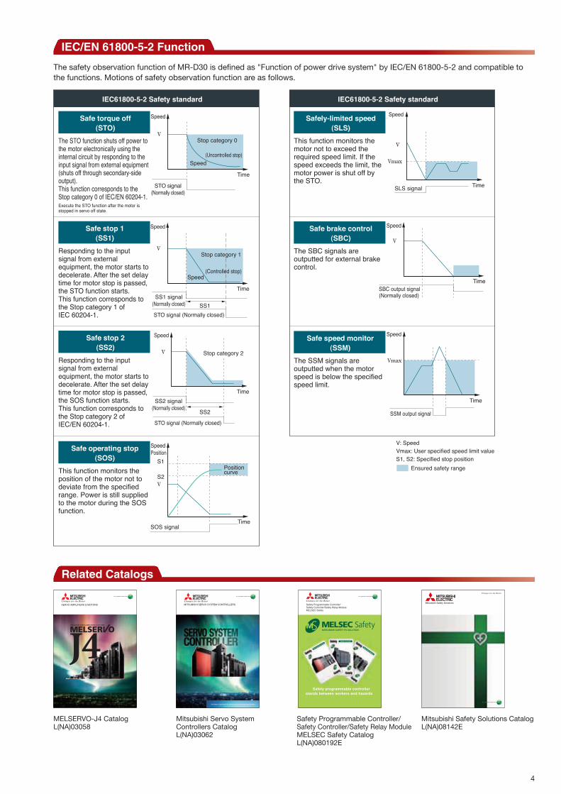
The safety observation function of MR-D30 is defined as "Function of power drive system" by IEC/EN 61800-5-2 and compatible to the functions. Motions of safety observation function are as follows.
IEC/EN 61800-5-2 Function
Related Catalogs
V: SpeedVmax: User specified speed limit valueS1, S2: Specified stop position
Ensured safety range
Safe speed monitor(SSM)
The SSM signals are outputted when the motor speed is below the specified speed limit.
The STO function shuts off power to the motor electronically using the internal circuit by responding to the input signal from external equipment (shuts off through secondary-side output).This function corresponds to the Stop category 0 of IEC/EN 60204-1.Execute the STO function after the motor is stopped in servo off state.
Safe stop 2(SS2)
Responding to the input signal from external equipment, the motor starts to decelerate. After the set delay time for motor stop is passed, the SOS function starts.This function corresponds to the Stop category 2 of IEC/EN 60204-1.
IEC61800-5-2 Safety standard IEC61800-5-2 Safety standard
Safe stop 1(SS1)
Responding to the input signal from external equipment, the motor starts to decelerate. After the set delay time for motor stop is passed, the STO function starts.This function corresponds to the Stop category 1 of IEC 60204-1.
Safe operating stop(SOS)
This function monitors the position of the motor not to deviate from the specified range. Power is still supplied to the motor during the SOS function.
Safely-limited speed(SLS)
This function monitors the motor not to exceed the required speed limit. If the speed exceeds the limit, the motor power is shut off by the STO.
Safe brake control(SBC)
Safe torque off(STO)
Speed
STO signal(Normally closed)
Time
Speed(Uncontrolled stop)
Stop category 0
Speed
SS1 signal(Normally closed) SS1STO signal (Normally closed)
Time
Speed(Controlled stop)
Stop category 1V
Time
Speed
V
Vmax
SLS signal
Speed
SBC output signal(Normally closed)
Time
V
The SBC signals are outputted for external brake control.
V
Speed
Time
V
STO signal (Normally closed)
SS2 signal(Normally closed) SS2
Time
SSM output signal
Speed
VmaxStop category 2
SpeedPosition
Time
S1
S2
SOS signal
Positioncurve
V
MELSERVO-J4 CatalogL(NA)03058
SERVO AMPLIFIERS & MOTORS
Mitsubishi Servo System Controllers CatalogL(NA)03062
The leader in productivity, safety and environmental performance
MITSUBISHI SERVO SYSTEM CONTROLLERS
Mitsubishi Safety Solutions CatalogL(NA)08142E
Mitsubishi Safety Solutions
Safety Programmable Controller/Safety Controller/Safety Relay Module MELSEC Safety CatalogL(NA)080192E
Safety Controller
Safety Programmable Controller
Safety Relay Module
Safety programmable controllerstands between workers and hazards
Safety Programmable Controller/Safety Controller/Safety Relay ModuleMELSEC Safety

5
MR-D30 Functional Safety UnitServo Motors with Functional Safety
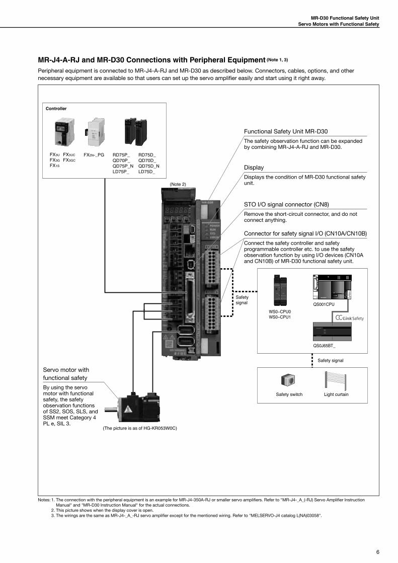
MR-J4-B-RJ and MR-D30 Connections with Peripheral Equipment (Note 1, 3)
Peripheral equipment is connected to MR-J4-B-RJ and MR-D30 as described below. Connectors, cables, options, and other necessary equipment are available so that users can set up the servo amplifier easily and start using it right away.
WS0−CPU0WS0−CPU1
QS001CPU
QS0J65BT_
Safety switch
(The picture is as of HG-KR053W0C)
Light curtain
RD77MS/QD77MS
Q170MSCPU
SSCNET III cable(option)
SSCNET III cable(option)
Safety signal
Safetysignal
(Note 2)
SSCNET III/H compatible servo system controllerR32MTCPU/R16MTCPUQ173DSCPU/Q172DSCPU
LD77MS
Notes: 1. The connection with the peripheral equipment is an example for MR-J4-350B-RJ or smaller servo amplifiers. Refer to "MR-J4-_B_(-RJ) Servo Amplifier Instruction Manual" and "MR-D30 Instruction Manual" for the actual connections.
2. This picture shows when the display cover is open. 3. The wirings are the same as MR-J4-_B_-RJ servo amplifier except for the mentioned wiring. Refer to "MELSERVO-J4 catalog L(NA)03058".
Functional Safety Unit MR-D30
The safety observation function can be expanded by combining MR-J4-B-RJ and MR-D30.
Display
Displays the condition of MR-D30 functional safety unit.
STO I/O signal connector (CN8)
Remove the short-circuit connector, and do not connect anything.
Connector for safety signal I/O (CN10A/CN10B)
Connect the safety controller and safety programmable controller etc. to use the safety observation function by using I/O devices (CN10A and CN10B) of MR-D30 functional safety unit.
SSCNET III/H connector (CN1A)
Connect the servo system controller or the previous servo amplifier axis.
Servo motor with functional safety
By using the servo motor with functional safety, the safety observation functions of SS2, SOS, SLS, and SSM meet Category 4 PL e, SIL 3.
SSCNET III/H connector (CN1B)
Connect the next servo amplifier axis.Be sure to attach a cap to CN1B connector of the final axis.
6
MR-D30 Functional Safety UnitServo Motors with Functional Safety
MR-J4-A-RJ and MR-D30 Connections with Peripheral Equipment (Note 1, 3)
Peripheral equipment is connected to MR-J4-A-RJ and MR-D30 as described below. Connectors, cables, options, and other necessary equipment are available so that users can set up the servo amplifier easily and start using it right away.
WS0−CPU0WS0−CPU1
QS001CPU
QS0J65BT_
Safety switch
(The picture is as of HG-KR053W0C)
Light curtain
FX2N-_PG
Safety signal
Safetysignal
(Note 2)
Controller
QD70P_RD75D_RD75P_QD70D_
QD75P_N QD75D_NLD75P_ LD75D_
FX3U FX3UCFX3G FX3GCFX1S
Notes: 1. The connection with the peripheral equipment is an example for MR-J4-350A-RJ or smaller servo amplifiers. Refer to "MR-J4-_A_(-RJ) Servo Amplifier Instruction Manual" and "MR-D30 Instruction Manual" for the actual connections.
2. This picture shows when the display cover is open. 3. The wirings are the same as MR-J4-_A_-RJ servo amplifier except for the mentioned wiring. Refer to "MELSERVO-J4 catalog L(NA)03058".
Functional Safety Unit MR-D30
The safety observation function can be expanded by combining MR-J4-A-RJ and MR-D30.
Display
Displays the condition of MR-D30 functional safety unit.
STO I/O signal connector (CN8)
Remove the short-circuit connector, and do not connect anything.
Connector for safety signal I/O (CN10A/CN10B)
Connect the safety controller and safety programmable controller etc. to use the safety observation function by using I/O devices (CN10A and CN10B) of MR-D30 functional safety unit.
Servo motor with functional safety
By using the servo motor with functional safety, the safety observation functions of SS2, SOS, SLS, and SSM meet Category 4 PL e, SIL 3.

7
MR-D30 Functional Safety UnitServo Motors with Functional Safety
Model Designation for Functional Safety Unit
M R - D 3 0 Functional safety unit
List of compatible software versionAchievable safety observation function depends on the software versions of MR-D30 and the servo amplifier, and compatibility of the servo motor with functional safety. Refer to the table below:
MR-D30software version
Servo amplifier software version
Safety observation function(IEC/EN 61800-5-2)
Servo motors with functional safety
Servo amplifier
A0B3/B4 STO/SS1/SBC/SLS/SSM Not usable MR-J4-_B_-RJ
B5 or later STO/SS1/SBC/SLS/SSM Not usable MR-J4-_B_-RJ
A1B3/B4 STO/SS1/SBC/SLS/SSM Not usable MR-J4-_B_-RJ
B5 or later STO/SS1/SBC/SLS/SSM/SOS/SS2 UsableMR-J4-_B_-RJ
MR-J4-_A_-RJ (Note 1)
Model Designation for Servo Amplifier
M R - J 4 - 1 0 B - R J
Symbol Rated output [kW]10 0.120 0.240 0.460 0.670 0.75100 1200 2350 3.5500 5700 711K 1115K 1522K 22
Symbol InterfaceB SSCNET III/HA General-purpose
Symbol Special specification
RJ
Fully closed loop control four-wire type/load-side encoder A/B/Z-phase
input compatible/Functional safety unit compatible (Note 7)/
Positioning mode compatible (Note 8)
RUMR-J4-_-RJ without a dynamic
brake (Note 1)
RZMR-J4-_-RJ without an enclosed
regenerative resistor (Note 4)
KJ MR-J4-_-RJ with DC power
input type (Note 6)
Mitsubishi general-
purpose AC servo amplifier MELSERVO-J4
Series
Notes: 1. Dynamic brake which is built in 7 kW or smaller servo amplifiers is removed. When using the servo amplifier without a dynamic brake, the servo motor does not stop immediately at alarm occurrence or power failure. Take measures to ensure safety on the entire system.When the following servo motors are used, an electronic dynamic brake may operate at alarm occurrence. HG-KR053, HG-KR13, HG-KR23, HG-KR43, HG-MR053, HG-MR13, HG-MR23, HG-MR43, HG-SR51, and HG-SR52Disable the electronic dynamic brake by setting the following parameter to "_ _ _ 2." For MR-J4-B-RJ: [Pr. PF06] For MR-J4-A-RJ: [Pr. PF09]In addition, when [Pr. PA04] is set to "2 _ _ _" (initial value), the servo motor may be decelerated to a stop forcibly at alarm occurrence. The forced stop deceleration function will be disabled by setting [Pr. PA04] to "0 _ _ _."
2. Servo amplifiers of 0.75 kW or smaller are available for 1-phase 200 V AC. 3. Servo amplifiers of 0.6 kW, and 1 kW or larger are available for 3-phase 400 V AC. 4. Available in 11 kW to 22 kW servo amplifier. A regenerative resistor (standard accessory) is not enclosed. 5. Servo amplifiers of 0.4 kW or smaller are available. 6. Contact your local sales office for the DC power input type servo amplifier. 7. When using MR-D30, use MR-J4-B-RJ servo amplifier with software version B3 or later, or MR-J4-A-RJ servo amplifier with software version B5 or later. 8. The positioning mode is available with MR-J4-A-RJ servo amplifiers. Use MR-J4-A-RJ servo amplifiers with software version B3 or later.
Symbol Power supply
None3-phase 200 V AC
or 1-phase 200 V AC (Note 2)
11-phase 100 V AC
(Note 5)
43-phase 400 V AC
(Note 3)
Notes: 1. MR-J4_A_-RJ manufactured in November 2014 or later is compatible with MR-D30.
8
MR-D30 Functional Safety UnitServo Motors with Functional Safety
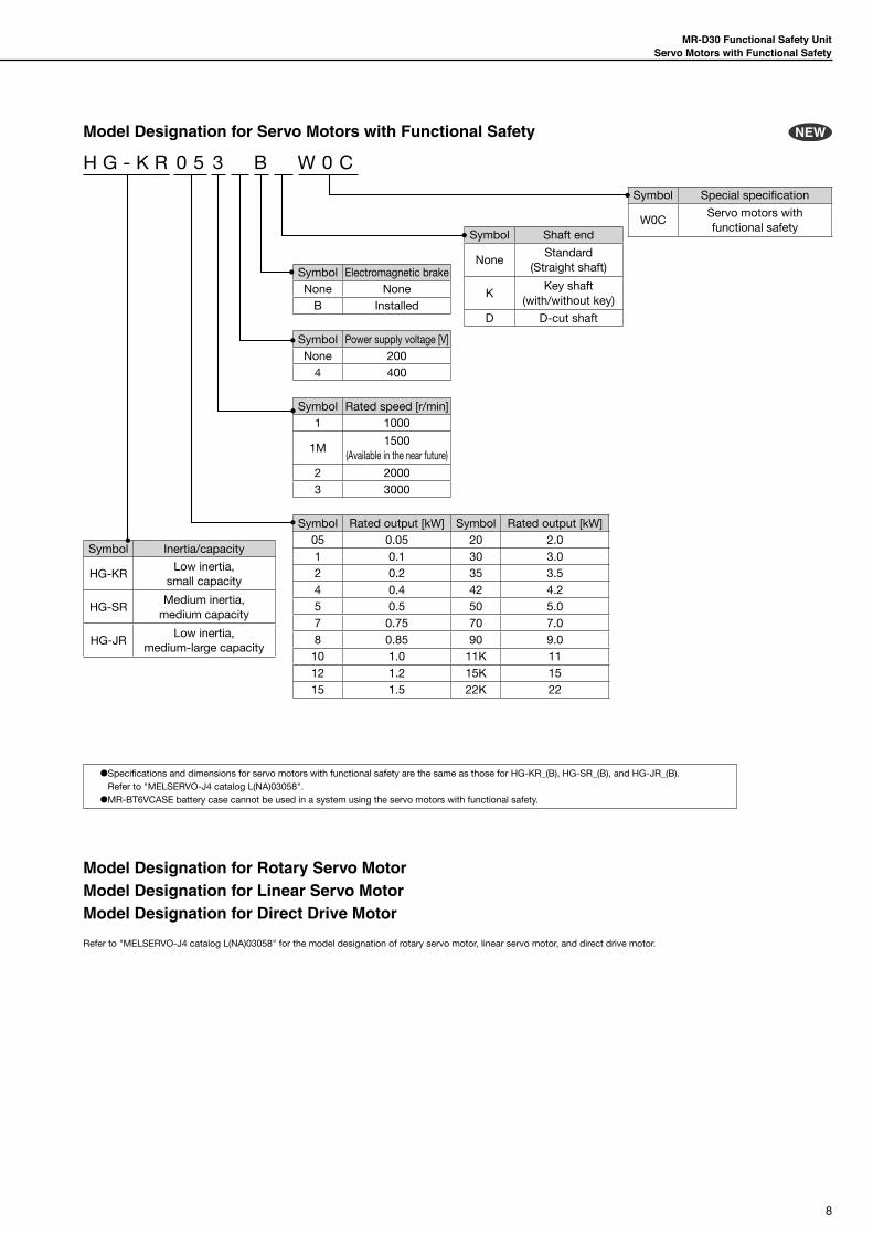
Symbol Shaft end
NoneStandard
(Straight shaft)
KKey shaft
(with/without key)
D D-cut shaft
Symbol Special specification
W0CServo motors with functional safety
Symbol Electromagnetic brakeNone None
B Installed
Symbol Power supply voltage [V]None 200
4 400
Symbol Rated speed [r/min]1 1000
1M1500
(Available in the near future)
2 20003 3000
Symbol Inertia/capacity
HG-KRLow inertia,
small capacity
HG-SRMedium inertia,
medium capacity
HG-JRLow inertia,
medium-large capacity
Symbol Rated output [kW] Symbol Rated output [kW]05 0.05 20 2.01 0.1 30 3.02 0.2 35 3.54 0.4 42 4.25 0.5 50 5.07 0.75 70 7.08 0.85 90 9.0
10 1.0 11K 1112 1.2 15K 1515 1.5 22K 22
NEWModel Designation for Servo Motors with Functional Safety
H G - K R 0 5 3 B W 0 C
●Specifications and dimensions for servo motors with functional safety are the same as those for HG-KR_(B), HG-SR_(B), and HG-JR_(B).Refer to "MELSERVO-J4 catalog L(NA)03058".
●MR-BT6VCASE battery case cannot be used in a system using the servo motors with functional safety.
Refer to "MELSERVO-J4 catalog L(NA)03058" for the model designation of rotary servo motor, linear servo motor, and direct drive motor.
Model Designation for Rotary Servo MotorModel Designation for Linear Servo MotorModel Designation for Direct Drive Motor

9
MR-D30 Functional Safety UnitServo Motors with Functional Safety
Combinations of Compatible Servo Amplifier and Servo Motor (200 V)
Servo amplifier Rotary servo motorServo motor with functional
safety Linear servo motor (primary side) (Note 1) Direct drive motor
MR-J4-10B-RJMR-J4-10A-RJ
HG-KR053, 13HG-MR053, 13
HG-KR053W0C, 13W0C - -
MR-J4-20B-RJMR-J4-20A-RJ
HG-KR23HG-MR23
HG-KR23W0CLM-U2PAB-05M-0SS0LM-U2PBB-07M-1SS0
TM-RFM002C20
MR-J4-40B-RJMR-J4-40A-RJ
HG-KR43HG-MR43
HG-KR43W0C
LM-H3P2A-07P-BSS0LM-H3P3A-12P-CSS0LM-K2P1A-01M-2SS1LM-U2PAD-10M-0SS0LM-U2PAF-15M-0SS0
TM-RFM004C20
MR-J4-60B-RJMR-J4-60A-RJ
HG-SR51, 52HG-JR53
HG-SR51W0C, 52W0CHG-JR53W0C
LM-U2PBD-15M-1SS0TM-RFM006C20TM-RFM006E20
MR-J4-70B-RJMR-J4-70A-RJ
HG-KR73HG-MR73HG-JR73HG-UR72
HG-KR73W0CHG-JR73W0C
LM-H3P3B-24P-CSS0LM-H3P3C-36P-CSS0LM-H3P7A-24P-ASS0LM-K2P2A-02M-1SS1LM-U2PBF-22M-1SS0
TM-RFM012E20TM-RFM012G20TM-RFM040J10
MR-J4-100B-RJMR-J4-100A-RJ
HG-SR81, 102HG-JR53 (Note 2), 103
HG-SR81W0C, 102W0CHG-JR53W0C (Note 2), 103W0C
- TM-RFM018E20
MR-J4-200B-RJMR-J4-200A-RJ
HG-SR121, 201, 152, 202HG-JR73 (Note 2), 103 (Note 2), 153, 203HG-RR103, 153HG-UR152
HG-SR121W0C, 201W0C, 152W0C, 202W0CHG-JR73W0C (Note 2), 103W0C (Note 2), 153W0C, 203W0C
LM-H3P3D-48P-CSS0LM-H3P7B-48P-ASS0LM-H3P7C-72P-ASS0LM-FP2B-06M-1SS0LM-K2P1C-03M-2SS1LM-U2P2B-40M-2SS0
-
MR-J4-350B-RJMR-J4-350A-RJ
HG-SR301, 352HG-JR153 (Note 2), 203 (Note 2), 353HG-RR203HG-UR202
HG-SR301W0C, 352W0CHG-JR153W0C (Note 2), 203W0C (Note 2), 353W0C
LM-H3P7D-96P-ASS0LM-K2P2C-07M-1SS1LM-K2P3C-14M-1SS1LM-U2P2C-60M-2SS0
TM-RFM048G20TM-RFM072G20TM-RFM120J10
MR-J4-500B-RJMR-J4-500A-RJ
HG-SR421, 502HG-JR353 (Note 2), 503HG-RR353, 503HG-UR352, 502
HG-SR421W0C, 502W0CHG-JR353W0C (Note 2), 503W0C
LM-FP2D-12M-1SS0LM-FP4B-12M-1SS0LM-K2P2E-12M-1SS1LM-K2P3E-24M-1SS1LM-U2P2D-80M-2SS0
TM-RFM240J10
MR-J4-700B-RJMR-J4-700A-RJ
HG-SR702HG-JR503 (Note 2), 703, 601, 701M
HG-SR702W0CHG-JR503W0C (Note 2), 703W0C, 701MW0C (Note 3)
LM-FP2F-18M-1SS0LM-FP4D-24M-1SS0
-
MR-J4-11KB-RJMR-J4-11KA-RJ
HG-JR903, 801, 12K1, 11K1MHG-JR903W0C, 11K1MW0C (Note 3) LM-FP4F-36M-1SS0 -
MR-J4-15KB-RJMR-J4-15KA-RJ
HG-JR15K1, 15K1M HG-JR15K1MW0C (Note 3) LM-FP4H-48M-1SS0 -
MR-J4-22KB-RJMR-J4-22KA-RJ
HG-JR20K1, 25K1, 22K1M HG-JR22K1MW0C (Note 3) - -
Notes: 1. Models of the linear servo motor primary side are listed in this page. For compatible models of the secondary side, refer to "Combination of Linear Servo Motor and Servo Amplifier" in "MELSERVO-J4 Catalog L(NA)03058".
2. The maximum torque can be increased from 300% to 400% of the rated torque with this combination. 3. Available in the near future.

10
MR-D30 Functional Safety UnitServo Motors with Functional Safety
Combinations of Compatible Servo Amplifier and Servo Motor (100 V)
Servo amplifier Rotary servo motorServo motor with functional
safety Linear servo motor (primary side) (Note 1) Direct drive motor
MR-J4-10B1-RJMR-J4-10A1-RJ
HG-KR053, 13HG-MR053, 13
HG-KR053W0C, 13W0C - -
MR-J4-20B1-RJMR-J4-20A1-RJ
HG-KR23HG-MR23
HG-KR23W0CLM-U2PAB-05M-0SS0LM-U2PBB-07M-1SS0
TM-RFM002C20
MR-J4-40B1-RJMR-J4-40A1-RJ
HG-KR43HG-MR43
HG-KR43W0C
LM-H3P2A-07P-BSS0LM-H3P3A-12P-CSS0LM-K2P1A-01M-2SS1LM-U2PAD-10M-0SS0LM-U2PAF-15M-0SS0
TM-RFM004C20
Combinations of Compatible Servo Amplifier and Servo Motor (400V)
Servo amplifier Rotary servo motorServo motor with functional
safety Linear servo motor (primary side) (Note 1) Direct drive motor
MR-J4-60B4-RJMR-J4-60A4-RJ
HG-SR524HG-JR534
HG-SR524W0CHG-JR534W0C
- -
MR-J4-100B4-RJMR-J4-100A4-RJ
HG-SR1024HG-JR534 (Note 2), 734, 1034
HG-SR1024W0CHG-JR534W0C (Note 2), 734W0C, 1034W0C
- -
MR-J4-200B4-RJMR-J4-200A4-RJ
HG-SR1524, 2024HG-JR734 (Note 2), 1034 (Note 2), 1534, 2034
HG-SR1524W0C, 2024W0CHG-JR734W0C (Note 2), 1034W0C (Note 2), 1534W0C, 2034W0C
- -
MR-J4-350B4-RJMR-J4-350A4-RJ
HG-SR3524HG-JR1534 (Note 2), 2034 (Note 2), 3534
HG-SR3524W0CHG-JR1534W0C (Note 2) 2034W0C (Note 2), 3534W0C
- -
MR-J4-500B4-RJMR-J4-500A4-RJ
HG-SR5024HG-JR3534 (Note 2), 5034
HG-SR5024W0CHG-JR3534W0C (Note 2), 5034W0C
- -
MR-J4-700B4-RJMR-J4-700A4-RJ
HG-SR7024HG-JR5034 (Note 2), 7034, 6014, 701M4
HG-SR7024W0CHG-JR5034W0C (Note 2), 7034W0C, 701M4W0C (Note 3)
- -
MR-J4-11KB4-RJMR-J4-11KA4-RJ
HG-JR9034, 8014, 12K14, 11K1M4
HG-JR9034W0C, 11K1M4W0C (Note 3) - -
MR-J4-15KB4-RJMR-J4-15KA4-RJ
HG-JR15K14, 15K1M4 HG-JR15K1M4W0C (Note 3) - -
MR-J4-22KB4-RJMR-J4-22KA4-RJ
HG-JR20K14, 25K14, 22K1M4 HG-JR22K1M4W0C (Note 3) LM-FP5H-60M-1SS0 -
Notes: 1. Models of the linear servo motor primary side are listed in this page. For compatible models of the secondary side, refer to "Combination of Linear Servo Motor and Servo Amplifier" in "MELSERVO-J4 Catalog L(NA)03058".
2. The maximum torque can be increased from 300% to 400% of the rated torque with this combination. 3. Available in the near future.
11
MR-D30 Functional Safety UnitServo Motors with Functional Safety
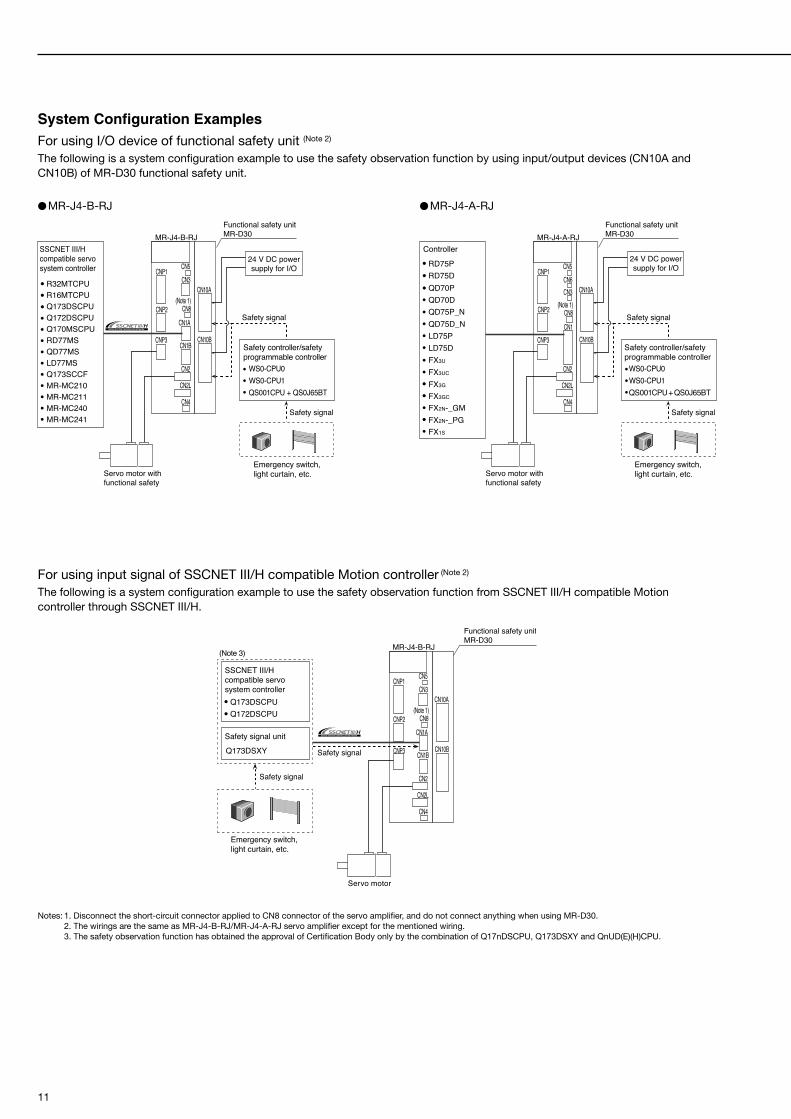
System Configuration ExamplesFor using I/O device of functional safety unit (Note 2)
The following is a system configuration example to use the safety observation function by using input/output devices (CN10A and CN10B) of MR-D30 functional safety unit.
For using input signal of SSCNET III/H compatible Motion controller (Note 2)
The following is a system configuration example to use the safety observation function from SSCNET III/H compatible Motion controller through SSCNET III/H.
Notes: 1. Disconnect the short-circuit connector applied to CN8 connector of the servo amplifier, and do not connect anything when using MR-D30. 2. The wirings are the same as MR-J4-B-RJ/MR-J4-A-RJ servo amplifier except for the mentioned wiring. 3. The safety observation function has obtained the approval of Certification Body only by the combination of Q17nDSCPU, Q173DSXY and QnUD(E)(H)CPU.
MR-J4-B-RJ
CNP2
CNP1 CN5CN3
CN8
CN1A
CN1B
CN2
CN2L
CN4
CNP3
CN10A
CN10B
Emergency switch, light curtain, etc.
24 V DC powersupply for I/O
Safety signal
Safety signal
Functional safety unitMR-D30
SSCNET III/H compatible servo system controller
Safety controller/safety programmable controller
(Note 1)
WS0-CPU0WS0-CPU1QS001CPU + QS0J65BT
R32MTCPUR16MTCPUQ173DSCPUQ172DSCPUQ170MSCPURD77MSQD77MSLD77MSQ173SCCFMR-MC210MR-MC211MR-MC240MR-MC241
Servo motor withfunctional safety
MR-J4-A-RJ
CNP2
CNP1 CN5CN6CN3
CN8
CN1
CN2
CN2L
CN4
CNP3
CN10A
CN10B
Emergency switch, light curtain, etc.
24 V DC powersupply for I/O
Safety signal
Safety signal
Functional safety unitMR-D30
Controller
Safety controller/safety programmable controller
QD70PQD70DQD75P_NQD75D_NLD75P
FX3U
LD75D
FX3UC
FX3G
FX3GC
FX2N-_GMFX2N-_PGFX1S
(Note 1)
WS0-CPU0WS0-CPU1QS001CPU+QS0J65BT
RD75PRD75D
Servo motor withfunctional safety
Safety signal
Safety signal
Emergency switch, light curtain, etc.
Functional safety unitMR-D30
SSCNET III/H compatible servo system controller
Q173DSCPUQ172DSCPU
Safety signal unit
Q173DSXY
(Note 3)MR-J4-B-RJ
CNP2
CNP1 CN5CN3
CN8
CN1A
CN1B
CN2
CN2L
CN4
CNP3
CN10A
CN10B
(Note 1)
Servo motor
●MR-J4-B-RJ ●MR-J4-A-RJ

12
MR-D30 Functional Safety UnitServo Motors with Functional Safety
SpecificationsModel MR-D30
OutputRated voltage 24 V DC
Rated current [A] 0.3
Interface power supplyVoltage 24 V DC ± 10%
Power supply capacity [A] 0.8 (Note 1)
Safety performance
Standards certified by CB
EN ISO 13849-1 Category 4 PL e and Category 3 PL dIEC 61508 SIL 2 and SIL 3
EN 62061 SIL CL 2 and SIL CL 3EN 61800-5-2 SIL 2 and SIL 3
Mean time to dangerous failure MTTFd ≥ 100 [year]Effectiveness of safety observation system or safety observation subsystem
DC = 90 [%]
Probability of dangerous Failure per Hour
PFH = 6.57 × 10⁻⁹ [1/h]
Mission time TM = 20 [year]
Response performance (Note 2) Using input device: 15 ms or less
Speed observation resolution Depends on a command resolution (0.1 r/min or less at 22-bit position command)
Position observation resolution 1/32 rev
Input device 6 points × 2 systems (source/sink)
Output deviceSource: 3 points × 2 systems and 1 point × 1 system
Sink: 1 point × 1 system
Safety observation function (IEC/EN 61800-5-2)
Safe torque off (STO) Category 4 PL e, SIL 3 (Note 3)/Category 3 PL d, SIL 2
Safe stop 1 (SS1) Category 4 PL e, SIL 3 (Note 3)/Category 3 PL d, SIL 2
Safe stop 2 (SS2) (Note 5, 6) Category 4 PL e, SIL 3 (Note 3)/Category 3 PL d, SIL 2
Safe operating stop (SOS) (Note 5, 6) Category 4 PL e, SIL 3 (Note 3)/Category 3 PL d, SIL 2
Safely-limited speed (SLS) (Note 5) Category 4 PL e, SIL 3 (Note 3, 4)/Category 3 PL d, SIL 2
Safe brake control (SBC) Category 4 PL e, SIL 3 (Note 3)/Category 3 PL d, SIL 2
Safe speed monitor (SSM) (Note 5) Category 4 PL e, SIL 3 (Note 3, 4)/Category 3 PL d, SIL 2Safety observation function
Status monitor (STO/SOS) Category 4 PL e, SIL 3/Category 3 PL d, SIL 2 (Note 7)
Compliance to global standards
CE markingEMC: EN 61800-3
MD: EN ISO 13849-1, EN 61800-5-2, EN 62061
Structure (IP rating)Natural cooling, open
(IP20 when mounted on servo amplifier and IP00 for MR-D30 alone)
Environment
Ambient temperature Operation: 0 ˚C to 55 ˚C (non-freezing), storage: -20 ˚C to 65 ˚C (non-freezing)
Ambient humidity Operation/Storage: 5 %RH to 90 %RH (non-condensing)
Ambience Indoors (no direct sunlight); no corrosive gas, inflammable gas, oil mist or dust
Altitude 1000 m or less above sea level
Vibration resistance 5.9 m/s2 at 10 Hz to 57 Hz
Mass [kg] 0.15Notes: 1. This is the value applicable when all I/O signals are used. The current capacity can be decreased by reducing the number of I/O points. 2. Time from STO input to energy shut off. 3. To meet Category 4 PL e, SIL 3, an input diagnosis using test pulse is required. 4. To meet Category 4 PL e, SIL 3, a combination with HG-KR_W0C, HG-SR_W0C, or HG-JR_W0C servo motor is required. 5. Linear servo system, direct drive servo system, and fully closed loop system are not compatible with SLS, SS2, and SOS. 6. To achieve SS2 and SOS, a combination with HG-KR_W0C, HG-SR_W0C, or HG-JR_W0C servo motor is required. 7. Refer to "MR-D30 Instruction Manual" for achievable safety level.

13
MR-D30 Functional Safety UnitServo Motors with Functional Safety
Connection Example
Notes: 1. Separate all of the external wirings into two systems. Connect separately even for the input and output power supply (24 V DC and 0 V common) connection. Do not wire between CN10A and CN10B.
2. Assign each I/O device by the combination of connector pins shown in the table below. Refer to "MR-D30 Instruction Manual" for each device.
3. Provide an external power supply of 24 V DC ± 10% for the interface. When all input/output points are used, the total current capacity of 0.8 A is required. The current capacity can be decreased by reducing the number of I/O points. For convenience of illustration, the diagram shows separate 24 V DC power supplies for input and output signals. However, the input and output signals can share a common power supply.
4. DO4PA (CN10A-16), DO4NA (CN10A-18), DO4PB (CN10B-16) and DO4NB (CN10B-18) are not available with MR-D30 manufactured in September 2014 or earlier. Do not connect anything to these pins.
8 DO1A
17 DO2A
9 DO3A
16 DO4PA
18 DO4NA
16DO4PB
18DO4NB
CN10A
Functional safety unitMR-D30
Servo amplifier
13DI2A
110
2
12
4
11
DC24VADC24VA
DICOMAPLSA
DI1A
DICOMA
7 DO24VA24 V DC (Note 3)
24 V DC (Note 3)
10 m or shorter
CN10A
24 V DC (Note 3)
(Note 4)
(Note 4)
(Note 4)
(Note 4)
(Note 1, 2)
Source output (Note 1, 2)
Source output (Note 1, 2)
Source output (Note 1, 2)
15
146
5DI4ADI3A
DI6ADI5A
8 DO1B
17 DO2B
9 DO3B
CN10B
13DI2B
110
2
12
4
11
DC24VBDC24VB
DICOMB
PLSB
DI1B
DICOMB
7 DO24VB
CN10B
15
146
5DI4BDI3B
DI6BDI5B
24 V DC (Note 3)
24 V DC (Note 3)
RA1
RA4
24 V DC (Note 3)
Sink output (Note 1, 2)
RA8
RA2
RA3
RA5
RA6
RA7
10 m or shorter
10 m or shorter10 m or shorter
(Note 1, 2)
CN7 CN9
CN70 CN90
Combination for input connector pin DI1A (CN10A-4)/DI1B (CN10B-4) DI2A (CN10A-13)/DI2B (CN10B-13) DI3A (CN10A-5)/DI3B (CN10B-5) DI4A (CN10A-14)/DI4B (CN10B-14) DI5A (CN10A-6)/DI5B (CN10B-6)DI6A (CN10A-15)/DI6B (CN10B-15)
Combination for output connector pinDO1A (CN10A-8)/DO1B (CN10B-8)DO2A (CN10A-17)/DO2B (CN10B-17)DO3A (CN10A-9)/DO3B (CN10B-9)DO4NA (CN10A-18)/DO4PB (CN10B-16)

14
MR-D30 Functional Safety UnitServo Motors with Functional Safety
Dimensions
20
28
95.4
99.2
104.2
5×6 mounting hole for grounding
97
114.
524
.5
Mounting screw size: M4
161
18 987654
12
17
15
1314
1011
16
12
18 987654
12
17
15
1314
1011
16
12
[Unit: mm]
15
MR-D30 Functional Safety UnitServo Motors with Functional Safety
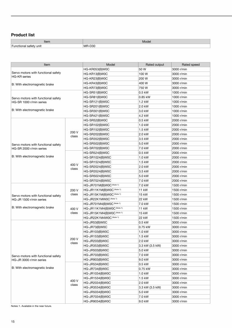
Item Model Rated output Rated speed
Servo motors with functional safetyHG-KR series
B: With electromagnetic brake
HG-KR053(B)W0C 50 W 3000 r/min
HG-KR13(B)W0C 100 W 3000 r/min
HG-KR23(B)W0C 200 W 3000 r/min
HG-KR43(B)W0C 400 W 3000 r/min
HG-KR73(B)W0C 750 W 3000 r/min
Servo motors with functional safetyHG-SR 1000 r/min series
B: With electromagnetic brake
HG-SR51(B)W0C 0.5 kW 1000 r/min
HG-SR81(B)W0C 0.85 kW 1000 r/min
HG-SR121(B)W0C 1.2 kW 1000 r/min
HG-SR201(B)W0C 2.0 kW 1000 r/min
HG-SR301(B)W0C 3.0 kW 1000 r/min
HG-SR421(B)W0C 4.2 kW 1000 r/min
Servo motors with functional safetyHG-SR 2000 r/min series
B: With electromagnetic brake
200 Vclass
HG-SR52(B)W0C 0.5 kW 2000 r/min
HG-SR102(B)W0C 1.0 kW 2000 r/min
HG-SR152(B)W0C 1.5 kW 2000 r/min
HG-SR202(B)W0C 2.0 kW 2000 r/min
HG-SR352(B)W0C 3.5 kW 2000 r/min
HG-SR502(B)W0C 5.0 kW 2000 r/min
HG-SR702(B)W0C 7.0 kW 2000 r/min
400 Vclass
HG-SR524(B)W0C 0.5 kW 2000 r/min
HG-SR1024(B)W0C 1.0 kW 2000 r/min
HG-SR1524(B)W0C 1.5 kW 2000 r/min
HG-SR2024(B)W0C 2.0 kW 2000 r/min
HG-SR3524(B)W0C 3.5 kW 2000 r/min
HG-SR5024(B)W0C 5.0 kW 2000 r/min
HG-SR7024(B)W0C 7.0 kW 2000 r/min
Servo motors with functional safetyHG-JR 1500 r/min series
B: With electromagnetic brake
200 Vclass
HG-JR701M(B)W0C (Note 1) 7.0 kW 1500 r/min
HG-JR11K1M(B)W0C (Note 1) 11 kW 1500 r/min
HG-JR15K1M(B)W0C (Note 1) 15 kW 1500 r/min
HG-JR22K1MW0C (Note 1) 22 kW 1500 r/min
400 Vclass
HG-JR701M4(B)W0C (Note 1) 7.0 kW 1500 r/min
HG-JR11K1M4(B)W0C (Note 1) 11 kW 1500 r/min
HG-JR15K1M4(B)W0C (Note 1) 15 kW 1500 r/min
HG-JR22K1M4W0C (Note 1) 22 kW 1500 r/min
Servo motors with functional safetyHG-JR 3000 r/min series
B: With electromagnetic brake
200 Vclass
HG-JR53(B)W0C 0.5 kW 3000 r/min
HG-JR73(B)W0C 0.75 kW 3000 r/min
HG-JR103(B)W0C 1.0 kW 3000 r/min
HG-JR153(B)W0C 1.5 kW 3000 r/min
HG-JR203(B)W0C 2.0 kW 3000 r/min
HG-JR353(B)W0C 3.3 kW (3.5 kW) 3000 r/min
HG-JR503(B)W0C 5.0 kW 3000 r/min
HG-JR703(B)W0C 7.0 kW 3000 r/min
HG-JR903(B)W0C 9.0 kW 3000 r/min
400 Vclass
HG-JR534(B)W0C 0.5 kW 3000 r/min
HG-JR734(B)W0C 0.75 kW 3000 r/min
HG-JR1034(B)W0C 1.0 kW 3000 r/min
HG-JR1534(B)W0C 1.5 kW 3000 r/min
HG-JR2034(B)W0C 2.0 kW 3000 r/min
HG-JR3534(B)W0C 3.3 kW (3.5 kW) 3000 r/min
HG-JR5034(B)W0C 5.0 kW 3000 r/min
HG-JR7034(B)W0C 7.0 kW 3000 r/min
HG-JR9034(B)W0C 9.0 kW 3000 r/minNotes: 1. Available in the near future.
Product listItem Model
Functional safety unit MR-D30
16
MR-D30 Functional Safety UnitServo Motors with Functional Safety
MEMO

17
MR-D30 Functional Safety UnitServo Motors with Functional Safety
MR-D30 Functional Safety UnitServo Motors with Functional Safety
MEMO

Safety WarningTo ensure proper use of the products listed in this catalog,please be sure to read the instruction manual prior to use.
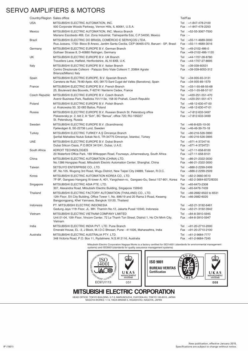
SERVO AMPLIFIERS & MOTORSCountry/Region Sales officeUSA MITSUBISHI ELECTRIC AUTOMATION, INC.
500 Corporate Woods Parkway, Vernon Hills, IL 60061, U.S.A.Mexico MITSUBISHI ELECTRIC AUTOMATION, INC. Mexico Branch
Mariano Escobedo #69, Col. Zona Industrial, Tlalnepantla Edo, C.P.54030, MexicoBrazil MITSUBISHI ELECTRIC DO BRASIL COMÉRCIO E SERVIÇOS LTDA.
Rua Jussara, 1750- Bloco B Anexo, Jardim Santa Cecilia, CEP 06465-070, Barueri - SP, BrasilGermany MITSUBISHI ELECTRIC EUROPE B.V. German Branch
Gothaer Strasse 8, D-40880 Ratingen, GermanyUK MITSUBISHI ELECTRIC EUROPE B.V. UK Branch
Travellers Lane, Hatfield, Hertfordshire, AL10 8XB, U.K.Italy MITSUBISHI ELECTRIC EUROPE B.V. Italian Branch
Centro Direzionale Colleoni - Palazzo Sirio Viale Colleoni 7, 20864 Agrate Brianza(Milano) Italy
Spain MITSUBISHI ELECTRIC EUROPE, B.V. Spanish BranchCarretera de Rubí, 76-80-Apdo. 420, 08173 Sant Cugat del Vallés (Barcelona), Spain
France MITSUBISHI ELECTRIC EUROPE B.V. French Branch25, Boulevard des Bouvets, F-92741 Nanterre Cedex, France
Czech Republic MITSUBISHI ELECTRIC EUROPE B.V. Czech BranchAvenir Business Park, Radlicka 751/113e, 158 00 Praha5, Czech Republic
Poland MITSUBISHI ELECTRIC EUROPE B.V. Polish Branchul. Krakowska 50, 32-083 Balice, Poland
Russia MITSUBISHI ELECTRIC EUROPE B.V. Russian Branch St. Petersburg officePiskarevsky pr. 2, bld 2, lit “Sch”, BC “Benua”, office 720; RU-195027 St. Petersburg, Russia
Sweden MITSUBISHI ELECTRIC EUROPE B.V. (Scandinavia) Fjelievägen 8, SE-22736 Lund, Sweden
Turkey MITSUBISHI ELECTRIC TURKEY A.Ş Ümraniye BranchŞerifali Mahallesi Nutuk Sokak No:5, TR-34775 Ümraniye, İstanbul, Türkey
UAE MITSUBISHI ELECTRIC EUROPE B.V. Dubai Branch Dubai Silicon Oasis, P.O.BOX 341241, Dubai, U.A.E.
South Africa ADROIT TECHNOLOGIES20 Waterford Office Park, 189 Witkoppen Road, Fourways, Johannesburg, South Africa
China MITSUBISHI ELECTRIC AUTOMATION (CHINA) LTD.No.1386 Hongqiao Road, Mitsubishi Electric Automation Center, Shanghai, China
Taiwan SETSUYO ENTERPRISE CO., LTD.6F, No.105, Wugong 3rd Road, Wugu District, New Taipei City 24889, Taiwan, R.O.C.
Korea MITSUBISHI ELECTRIC AUTOMATION KOREA CO., LTD. 7F-9F, Gangseo Hangang Xi-tower A, 401, Yangcheon-ro, Gangseo-Gu, Seoul 157-801, Korea
Singapore MITSUBISHI ELECTRIC ASIA PTE. LTD.307, Alexandra Road, Mitsubishi Electric Building, Singapore 159943
Thailand MITSUBISHI ELECTRIC FACTORY AUTOMATION (THAILAND) CO., LTD.12th Floor, SV.City Building, Office Tower 1, No. 896/19 and 20 Rama 3 Road, Kwaeng Bangpongpang, Khet Yannawa, Bangkok 10120, Thailand
Indonesia PT. MITSUBISHI ELECTRIC INDONESIAGedung Jaya 11th Floor, JL. MH. Thamrin No.12, Jakarta Pusat 10340, Indonesia
Vietnam MITSUBISHI ELECTRIC VIETNAM COMPANY LIMITED Unit 01-04, 10th Floor, Vincom Center, 72 Le Thanh Ton Street, District 1, Ho Chi Minh City, Vietnam
India MITSUBISHI ELECTRIC INDIA PVT. LTD. Pune BranchEmerald House, EL -3, J Block, M.I.D.C Bhosari, Pune - 411026, Maharashtra, India
Australia MITSUBISHI ELECTRIC AUSTRALIA PTY. LTD.348 Victoria Road, P.O. Box 11, Rydalmere, N.S.W 2116, Australia
Tel/FaxTel : +1-847-478-2100Fax : +1-847-478-2253Tel : +52-55-3067-7500Fax : –Tel : +55-11-4689-3000Fax : +55-11-4689-3016Tel : +49-2102-486-0Fax : +49-2102-486-1120Tel : +44-1707-28-8780Fax : +44-1707-27-8695Tel : +39-039-60531Fax : +39-039-6053-312
Tel : +34-935-65-3131Fax : +34-935-89-1579Tel : +33-1-55-68-55-68Fax : +33-1-55-68-57-57Tel : +420-251-551-470Fax : +420-251-551-471Tel : +48-12-630-47-00Fax : +48-12-630-47-01Tel : +7-812-633-3497Fax : +7-812-633-3499
Tel : +46-8-625-10-00Fax : +46-46-39-70-18Tel : +90-216-526-3990 Fax : +90-216-526-3995Tel : +971-4-3724716 Fax : +971-4-3724721 Tel : +27-11-658-8100Fax : +27-11-658-8101Tel : +86-21-2322-3030Fax : +86-21-2322-3000Tel : +886-2-2299-2499Fax : +886-2-2299-2509Tel : +82-2-3660-9510Fax : +82-2-3664-8372/8335Tel : +65-6473-2308Fax : +65-6476-7439Tel : +66-2682-6522 to 6531Fax : +66-2682-6020
Tel : +62-21-3192-6461Fax : +62-21-3192-3942Tel : +84-8-3910-5945Fax : +84-8-3910-5947
Tel : +91-20-2710-2000Fax : +91-20-2710-2100Tel : +61-2-9684-7777Fax : +61-2-9684-7245
New publication, effective January 2015.Specifications are subject to change without notice.IP (1501)