swisslog pneumatic tube system network communications deployment guide · 2018-06-11 · a...
TRANSCRIPT

Tech
nica
l Doc
umen
ts Li
brar
y | 2
0180
314
| PN
991
1162
2_M
| EC
N 2
2182
SWISSLOG HEALTHCARE
Swisslog Pneumatic Tube SystemNetwork Communications Deployment Guide
©Swisslog Healthcare 2018. Property of Swisslog. This document contains confidential and proprietary information intended for use by Swisslog and its customers only. Trans-fer to third parties is permissible only with the consent of Swisslog. Transfer without consent may result in civil penalties.
The Swisslog Pneumatic Tube System is provided as-is, without any guarantees or war-ranty. In association with the product, Swisslog makes no warranties—either express orimplied—of any kind, including but not limited to warranties of merchantability, fitnessfor a particular purpose, of title, or of non-infringement of third-party rights. Use of theproduct is at the user’s risk.
Contents
Network Integration . . . . . . . . . . . . . . . . . . . . . . . . . . . . . . . . . . . 1The Pneumatic Tube System environment. . . . . . . . . . . . . . . . . . . . . . . . . . . . . . . 1
Client/server architecture . . . . . . . . . . . . . . . . . . . . . . . . . . . . . . . . . . . . . . . . . . . . . . . . . 1Remote clients. . . . . . . . . . . . . . . . . . . . . . . . . . . . . . . . . . . . . . . . . . . . . . . . . . . . . . . . . . 2
Communication protocols. . . . . . . . . . . . . . . . . . . . . . . . . . . . . . . . . . . . . . . . . . . 2User Datagram Protocol . . . . . . . . . . . . . . . . . . . . . . . . . . . . . . . . . . . . . . . . . . . . . . . . . . 2Serial communication. . . . . . . . . . . . . . . . . . . . . . . . . . . . . . . . . . . . . . . . . . . . . . . . . . . . 2
The Pneumatic Tube System on the network . . . . . . . . . . . . . . . . . . . . . . . . . . . . 3100% Ethernet devices. . . . . . . . . . . . . . . . . . . . . . . . . . . . . . . . . . . . . . . . . . . . . . . . . . . 3Mixed serial and Ethernet communications . . . . . . . . . . . . . . . . . . . . . . . . . . . . . . . . . . 3100% serial devices . . . . . . . . . . . . . . . . . . . . . . . . . . . . . . . . . . . . . . . . . . . . . . . . . . . . . 4100% serial devices with fiber optic lines . . . . . . . . . . . . . . . . . . . . . . . . . . . . . . . . . . . 5
Network Configuration Requirements . . . . . . . . . . . . . . . . . . . . . . 7VLAN Specifications . . . . . . . . . . . . . . . . . . . . . . . . . . . . . . . . . . . . . . . . . . . . . . . 7
Segmenting . . . . . . . . . . . . . . . . . . . . . . . . . . . . . . . . . . . . . . . . . . . . . . . . . . . . . . . . . . . . 7IP addressing . . . . . . . . . . . . . . . . . . . . . . . . . . . . . . . . . . . . . . . . . . . . . . . . . . . . . . . . . . . 8Latency. . . . . . . . . . . . . . . . . . . . . . . . . . . . . . . . . . . . . . . . . . . . . . . . . . . . . . . . . . . . . . . . 8Internet connection . . . . . . . . . . . . . . . . . . . . . . . . . . . . . . . . . . . . . . . . . . . . . . . . . . . . . 8FTP service . . . . . . . . . . . . . . . . . . . . . . . . . . . . . . . . . . . . . . . . . . . . . . . . . . . . . . . . . . . . . 9
Network security . . . . . . . . . . . . . . . . . . . . . . . . . . . . . . . . . . . . . . . . . . . . . . . . . 9Antivirus and malware detection. . . . . . . . . . . . . . . . . . . . . . . . . . . . . . . . . . . . . . . . . . . 9Windows firewalls. . . . . . . . . . . . . . . . . . . . . . . . . . . . . . . . . . . . . . . . . . . . . . . . . . . . . . . 10White list sites. . . . . . . . . . . . . . . . . . . . . . . . . . . . . . . . . . . . . . . . . . . . . . . . . . . . . . . . . . 10Proxy Servers . . . . . . . . . . . . . . . . . . . . . . . . . . . . . . . . . . . . . . . . . . . . . . . . . . . . . . . . . . . 10Encryption . . . . . . . . . . . . . . . . . . . . . . . . . . . . . . . . . . . . . . . . . . . . . . . . . . . . . . . . . . . . . 10Network access control . . . . . . . . . . . . . . . . . . . . . . . . . . . . . . . . . . . . . . . . . . . . . . . . . . 10Network scanning utilities . . . . . . . . . . . . . . . . . . . . . . . . . . . . . . . . . . . . . . . . . . . . . . . . 10SMTP server access . . . . . . . . . . . . . . . . . . . . . . . . . . . . . . . . . . . . . . . . . . . . . . . . . . . . . . 11
Remote access requirements. . . . . . . . . . . . . . . . . . . . . . . . . . . . . . . . . . . . . . . . . 11
Physical Server Specifications and Administration . . . . . . . . . . . . 13Group policies . . . . . . . . . . . . . . . . . . . . . . . . . . . . . . . . . . . . . . . . . . . . . . . . . . . 13Windows updates and patches . . . . . . . . . . . . . . . . . . . . . . . . . . . . . . . . . . . . . . . 13
PTS AND SCC | NETWORK COMMUNICATIONS DEPLOYMENT GUIDE MAR/2018

iv Contents
Disk memory management . . . . . . . . . . . . . . . . . . . . . . . . . . . . . . . . . . . . . . . . . . 14System Center Configuration Manager . . . . . . . . . . . . . . . . . . . . . . . . . . . . . . . . . 14Server and software redundancy . . . . . . . . . . . . . . . . . . . . . . . . . . . . . . . . . . . . . 14PC and operating system configuration . . . . . . . . . . . . . . . . . . . . . . . . . . . . . . . . 14User accounts and permissions . . . . . . . . . . . . . . . . . . . . . . . . . . . . . . . . . . . . . . . 14Power management . . . . . . . . . . . . . . . . . . . . . . . . . . . . . . . . . . . . . . . . . . . . . . . 14Windows indexing . . . . . . . . . . . . . . . . . . . . . . . . . . . . . . . . . . . . . . . . . . . . . . . . 15Fast user switching. . . . . . . . . . . . . . . . . . . . . . . . . . . . . . . . . . . . . . . . . . . . . . . . 15Hardware specifications . . . . . . . . . . . . . . . . . . . . . . . . . . . . . . . . . . . . . . . . . . . . 15
Server-class machines and workstations . . . . . . . . . . . . . . . . . . . . . . . . . . . . . . . . . . . . 15Remote client specifications . . . . . . . . . . . . . . . . . . . . . . . . . . . . . . . . . . . . . . . . . . . . . . 16Monitor specifications . . . . . . . . . . . . . . . . . . . . . . . . . . . . . . . . . . . . . . . . . . . . . . . . . . . 17Network devices . . . . . . . . . . . . . . . . . . . . . . . . . . . . . . . . . . . . . . . . . . . . . . . . . . . . . . . . 17
USB networking devices . . . . . . . . . . . . . . . . . . . . . . . . . . . . . . . . . . . . . . . . . . . . . . . 17Network interface cards . . . . . . . . . . . . . . . . . . . . . . . . . . . . . . . . . . . . . . . . . . . . . . . 17Switches . . . . . . . . . . . . . . . . . . . . . . . . . . . . . . . . . . . . . . . . . . . . . . . . . . . . . . . . . . . . 17Concealing network devices . . . . . . . . . . . . . . . . . . . . . . . . . . . . . . . . . . . . . . . . . . . . 17
Cable requirements and specifications . . . . . . . . . . . . . . . . . . . . . . . . . . . . . . . . . 18Fiber optic cable . . . . . . . . . . . . . . . . . . . . . . . . . . . . . . . . . . . . . . . . . . . . . . . . . . . . . . . . 18
Virtual Server Specifications and Administration . . . . . . . . . . . . . 19VM requirements and specifications . . . . . . . . . . . . . . . . . . . . . . . . . . . . . . . . . . . 19
Requirements for VM installations . . . . . . . . . . . . . . . . . . . . . . . . . . . . . . . . . . . . . . . . . 20VM specifications . . . . . . . . . . . . . . . . . . . . . . . . . . . . . . . . . . . . . . . . . . . . . . . . . . . . . . . 20Clients in a VM environment . . . . . . . . . . . . . . . . . . . . . . . . . . . . . . . . . . . . . . . . . . . . . . 21
VM Administration. . . . . . . . . . . . . . . . . . . . . . . . . . . . . . . . . . . . . . . . . . . . . . . . 21Configure power system settings. . . . . . . . . . . . . . . . . . . . . . . . . . . . . . . . . . . . . . . . . . . 21Configure TCP/IP and UDP settings . . . . . . . . . . . . . . . . . . . . . . . . . . . . . . . . . . . . . . . . . 21Configure the network adapter . . . . . . . . . . . . . . . . . . . . . . . . . . . . . . . . . . . . . . . . . . . . 22
MAR/2018 NETWORK COMMUNICATIONS DEPLOYMENT GUIDE | PTS AND SCC
CHAPTER 1 Network Integration
PTS AND SCC | NETWORK COM
©2018 SWISSLOG HEALTHCARE. THIS DOCTRANSFER TO THIRD PARTIES IS PERMISSIBL
Requirements for integrating the tube system into a site network
This document provides IT administrators, network administrators and server administrators with the net-work and communications requirements and specifications required to implement a Swisslog Pneumatic Tube System (PTS) running Nexus™ Software on an established or planned site network.
The Pneumatic Tube System environmentThe PTS consists of one System Control Center (SCC) computer/server, transmission devices, piping and optional remote client computers. The SCC software controls and monitors the various transmission devices in the tube system through the site’s local area network or through dedicated serial communication lines in the case of legacy installations.
Client/server architectureThe SCC software uses a client-server architecture that communicates through a TCP/IP connection (socket). The client program is written in Java and runs in a Java virtual machine. This environment is installed entirely within the Swisslog folder structure and does not use or alter any other Java installations present on the host PC.
The server application is Windows®-based and runs in its own application window (hidden by default). The SCC primary computer hosts the server portion of the software and also typically hosts a single client.
MUNICATIONS DEPLOYMENT GUIDE MAR/2018
UMENT CONTAINS CONFIDENTIAL AND PROPRIETARY INFORMATION INTENDED FOR USE BY SWISSLOG AND ITS CUSTOMERS ONLY. E ONLY WITH THE WRITTEN CONSENT OF SWISSLOG. TRANSFER WITHOUT CONSENT MAY RESULT IN CIVIL PENALTIES.
2 Network Integration | Communication protocols
Remote clientsAdditional clients (remote clients) may connect to the server through the network. Remote clients must run a supported operating system as listed in “Remote client specifications” on page 16.
Communication protocolsTube system devices communicate with the SCC via Ethernet lines, serial lines or a mixture of the two. Lim-itations apply to virtual machines, see “Virtual Server Specifications and Administration” on page 19.
User Datagram ProtocolOver Ethernet, the tube system uses UDP messaging; its low bandwidth requirements permit existing site networks to host the tube system with little or no impact to other network devices. UDP does not have its own error checking or require a communication handshake before transmitting messages. The SCC monitors whether each device is active on the network, so it does not need a protocol with error checking. The SCC pings each device, and once it receives a reply the SCC is assured that it is sending data to the correct device and proceeds with the actual data transmission.
Serial communicationOver serial lines, RS-422/485 signals are converted to RS-232 by a Communication Interface Assembly (CIA) at which point the DeviceMaster converts them to a User Datagram Protocol (UDP) signal to interface with the SCC.
Three remote client connections are supported and included with an initial Nexus license and three additional clients may be licensed for a total of six remote clients.
All systems upgrading to Nexus Software require communication line validation not limited to the following:
• all communication line connection points are in good condition and fully seated,
• junction boxes at tube system devices are in good condition and wired correctly,
• Swisslog-approved wire and cabling is present throughout the system and
• Communication Interface Assemblies are re-wired with fresh splices from lines at connectors.
MAR/2018 NETWORK COMMUNICATIONS DEPLOYMENT GUIDE | PTS AND SCC
Network Integration | The Pneumatic Tube System on the network 3
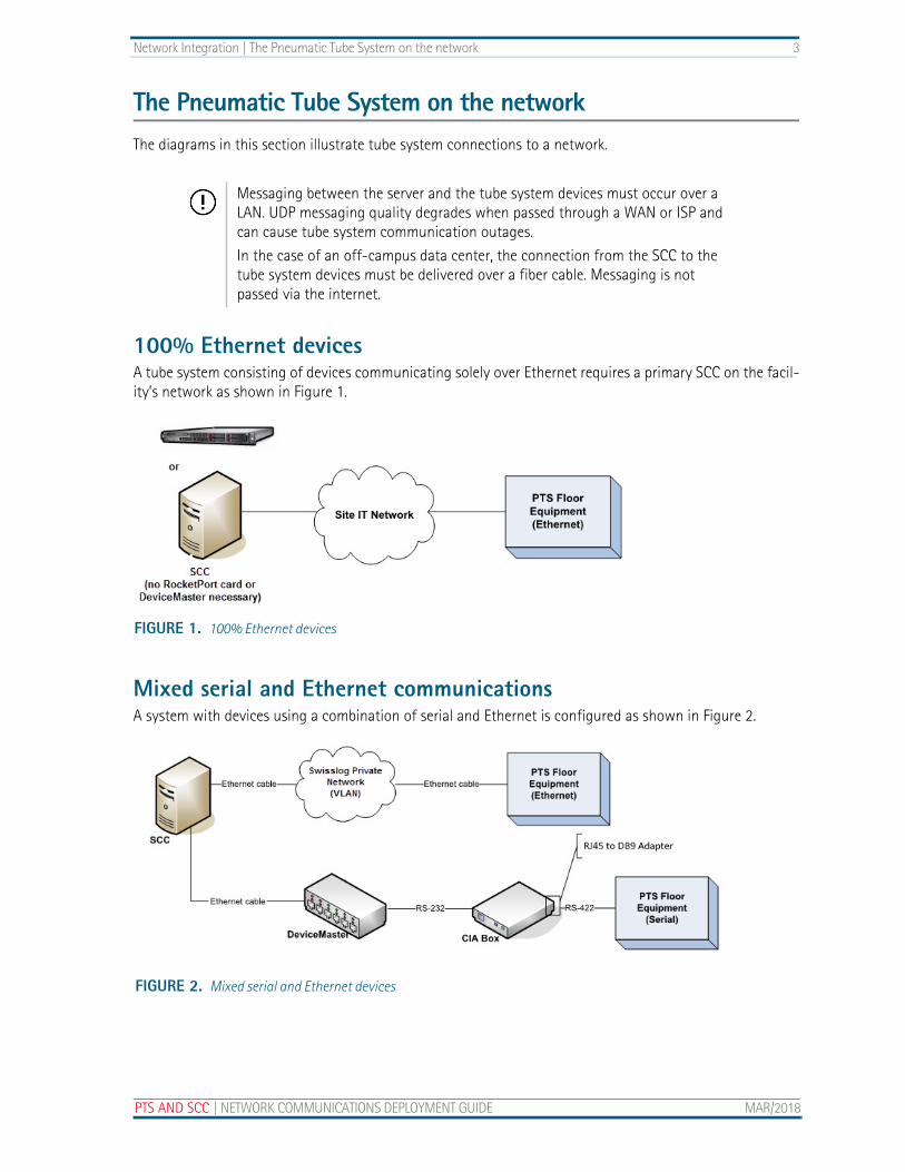
The Pneumatic Tube System on the networkThe diagrams in this section illustrate tube system connections to a network.
100% Ethernet devicesA tube system consisting of devices communicating solely over Ethernet requires a primary SCC on the facil-ity’s network as shown in Figure 1.
Mixed serial and Ethernet communicationsA system with devices using a combination of serial and Ethernet is configured as shown in Figure 2.
Messaging between the server and the tube system devices must occur over a LAN. UDP messaging quality degrades when passed through a WAN or ISP and can cause tube system communication outages.
In the case of an off-campus data center, the connection from the SCC to the tube system devices must be delivered over a fiber cable. Messaging is not passed via the internet.
FIGURE 1. 100% Ethernet devices
FIGURE 2. Mixed serial and Ethernet devices
PTS AND SCC | NETWORK COMMUNICATIONS DEPLOYMENT GUIDE MAR/2018

4 Network Integration | The Pneumatic Tube System on the network
100% serial devicesFor new installations, a DeviceMaster is installed near the primary SCC and Communication Interface Assemblies (CIAs).
When migrating an existing system from serial communications to Ethernet communications, devices can be configured as described above or in one of these options:
• Option 1: Leave the CIAs and serial communications lines in place, install the appropriate DeviceMas-ter at the existing CIAs and run a dedicated Ethernet line to the SCC.
• Option 2: Leave the CIAs and serial communications lines in place, install the appropriate DeviceMas-ter near the SCC. Install the appropriate length RS-232 cables between the CIAs and DeviceMaster.
Figure 3 shows a system with serial devices connected to the SCC.
FIGURE 3. 100% serial devices
MAR/2018 NETWORK COMMUNICATIONS DEPLOYMENT GUIDE | PTS AND SCC
Network Integration | The Pneumatic Tube System on the network 5
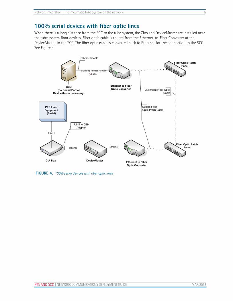
100% serial devices with fiber optic linesWhen there is a long distance from the SCC to the tube system, the CIAs and DeviceMaster are installed near the tube system floor devices. Fiber optic cable is routed from the Ethernet-to-Fiber Converter at the DeviceMaster to the SCC. The fiber optic cable is converted back to Ethernet for the connection to the SCC. See Figure 4.
FIGURE 4. 100% serial devices with fiber optic lines
PTS AND SCC | NETWORK COMMUNICATIONS DEPLOYMENT GUIDE MAR/2018

6 Network Integration | The Pneumatic Tube System on the network
MAR/2018 NETWORK COMMUNICATIONS DEPLOYMENT GUIDE | PTS AND SCC
CHAPTER 2 Network Configuration Requirements
PTS AND SCC | NETWORK COM
©2018 SWISSLOG HEALTHCARE. THIS DOCTRANSFER TO THIRD PARTIES IS PERMISSIBL
Specifications for the dedicated tube system network space
This chapter addresses specifications and requirements for the following:
• VLAN Specifications
• Network security
• Remote access requirements
VLAN SpecificationsThe site IT network hosts the services used by PTS equipment. Cable maintenance and network troubleshoot-ing are owned by the site IT department.
SegmentingA segregated virtual local area network (VLAN) dedicated to the tube system is required to isolate tube sys-tem traffic, allow for proper packet handling and provide reliable system operation.
Multiple VLANs are acceptable, but must be segregated for Swisslog use only. There is no restriction on the subnets used, but routing must be configured to allow all devices to communicate with the SCC across the Swisslog VLAN.
MUNICATIONS DEPLOYMENT GUIDE MAR/2018
UMENT CONTAINS CONFIDENTIAL AND PROPRIETARY INFORMATION INTENDED FOR USE BY SWISSLOG AND ITS CUSTOMERS ONLY. E ONLY WITH THE WRITTEN CONSENT OF SWISSLOG. TRANSFER WITHOUT CONSENT MAY RESULT IN CIVIL PENALTIES.
8 Network Configuration Requirements | VLAN Specifications
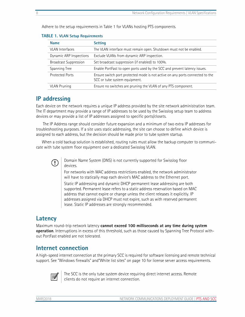
Adhere to the setup requirements in Table 1 for VLANs hosting PTS components.
IP addressingEach device on the network requires a unique IP address provided by the site network administration team. The IT department may provide a range of IP addresses to be used by the Swisslog setup team to address devices or may provide a list of IP addresses assigned to specific ports/closets.
The IP Address range should consider future expansion and a minimum of two extra IP addresses for troubleshooting purposes. If a site uses static addressing, the site can choose to define which device is assigned to each address, but the decision should be made prior to tube system startup.
When a cold backup solution is established, routing rules must allow the backup computer to communi-cate with tube system floor equipment over a dedicated Swisslog VLAN.
LatencyMaximum round-trip network latency cannot exceed 100 milliseconds at any time during system operation. Interruptions in excess of this threshold, such as those caused by Spanning Tree Protocol with-out PortFast enabled are not tolerated.
Internet connectionA high-speed internet connection at the primary SCC is required for software licensing and remote technical support. See "Windows firewalls" and“White list sites” on page 10 for license server access requirements.
TABLE 1. VLAN Setup Requirements
Name Setting
VLAN Interfaces The VLAN interface must remain open. Shutdown must not be enabled.
Dynamic ARP Inspections Exclude VLANs from dynamic ARP inspection.
Broadcast Suppression Set broadcast suppression (if enabled) to 100%.
Spanning Tree Enable PortFast to open ports used by the SCC and prevent latency issues.
Protected Ports Ensure switch port protected mode is not active on any ports connected to the SCC or tube system equipment.
VLAN Pruning Ensure no switches are pruning the VLAN of any PTS component.
Domain Name System (DNS) is not currently supported for Swisslog floor devices.
For networks with MAC address restrictions enabled, the network administrator will have to statically map each device’s MAC address to the Ethernet port.
Static IP addressing and dynamic DHCP permanent lease addressing are both supported. Permanent lease refers to a static address reservation based on MAC address that cannot expire or change unless the client releases it explicitly. IP addresses assigned via DHCP must not expire, such as with reserved permanent lease. Static IP addresses are strongly recommended.
The SCC is the only tube system device requiring direct internet access. Remote clients do not require an internet connection.
MAR/2018 NETWORK COMMUNICATIONS DEPLOYMENT GUIDE | PTS AND SCC
Network Configuration Requirements | Network security 9
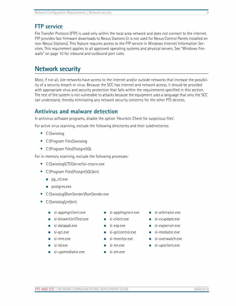
FTP serviceFile Transfer Protocol (FTP) is used only within the local area network and does not connect to the internet. FTP provides fast firmware downloads to Nexus Stations (it is not used for Nexus Control Panels installed on non-Nexus Stations). This feature requires access to the FTP service in Windows Internet Information Ser-vices. This requirement applies to all approved operating systems and physical servers. See “Windows fire-walls” on page 10 for inbound and outbound port rules.
Network securityMost, if not all, site networks have access to the internet and/or outside networks that increase the possibil-ity of a security breach or virus. Because the SCC has internet and network access, it should be provided with appropriate virus and security protection that falls within the requirements specified in this section. The rest of the system is not vulnerable to attacks because the equipment uses a language that only the SCC can understand, thereby eliminating any network security concerns for the other PTS devices.
Antivirus and malware detectionIn antivirus software programs, disable the option ‘Heuristic Check for suspicious files’.
For active virus scanning, exclude the following directories and their subdirectories:
• C:\Swisslog
• C:\Program Files\Swisslog
• C:\Program Files\PostgreSQL
For in-memory scanning, exclude the following processes:
• C:\Swisslog\CTS\Server\sl-ctssrvr.exe
• C:\Program Files\PostgreSQL\bin\
pg_ctl.exe
postgres.exe
• C:\Swisslog\RsmSender\RsmSender.exe
• C:\Swisslog\jre\bin\
sl-appmgrclient.exe sl-applmgrsrvr.exe sl-arbitrator.exe
sl-blowerUnitTest.exe sl-client.exe sl-cxupdate.exe
sl-datapak.exe sl-esp.exe sl-espserver.exe
sl-gci.exe sl-gcicontrol.exe sl-mediator.exe
sl-mm.exe sl-monitor.exe sl-overwatch.exe
sl-td.exe sl-tm.exe sl-upsclient.exe
sl-upsmediator.exe sl-zm.exe
PTS AND SCC | NETWORK COMMUNICATIONS DEPLOYMENT GUIDE MAR/2018
10 Network Configuration Requirements | Network security
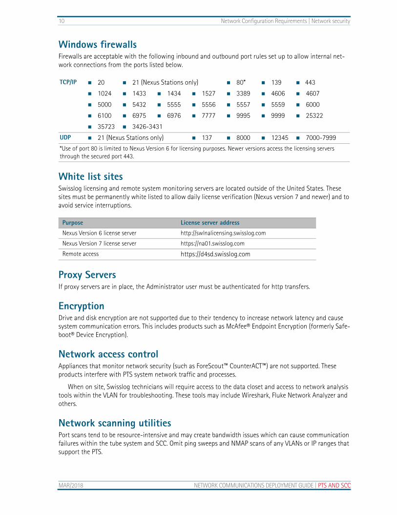
Windows firewallsFirewalls are acceptable with the following inbound and outbound port rules set up to allow internal net-work connections from the ports listed below.
White list sitesSwisslog licensing and remote system monitoring servers are located outside of the United States. These sites must be permanently white listed to allow daily license verification (Nexus version 7 and newer) and to avoid service interruptions.
Proxy ServersIf proxy servers are in place, the Administrator user must be authenticated for http transfers.
EncryptionDrive and disk encryption are not supported due to their tendency to increase network latency and cause system communication errors. This includes products such as McAfee® Endpoint Encryption (formerly Safe-boot® Device Encryption).
Network access controlAppliances that monitor network security (such as ForeScout™ CounterACT™) are not supported. These products interfere with PTS system network traffic and processes.
When on site, Swisslog technicians will require access to the data closet and access to network analysis tools within the VLAN for troubleshooting. These tools may include Wireshark, Fluke Network Analyzer and others.
Network scanning utilitiesPort scans tend to be resource-intensive and may create bandwidth issues which can cause communication failures within the tube system and SCC. Omit ping sweeps and NMAP scans of any VLANs or IP ranges that support the PTS.
TCP/IP 20 21 (Nexus Stations only) 80* 139 443
1024 1433 1434 1527 3389 4606 4607
5000 5432 5555 5556 5557 5559 6000
6100 6975 6976 7777 9995 9999 25322
35723 3426-3431
UDP 21 (Nexus Stations only) 137 8000 12345 7000-7999
*Use of port 80 is limited to Nexus Version 6 for licensing purposes. Newer versions access the licensing servers through the secured port 443.
Purpose License server address
Nexus Version 6 license server http://swlnalicensing.swisslog.com
Nexus Version 7 license server https://na01.swisslog.com
Remote access https://d4sd.swisslog.com
MAR/2018 NETWORK COMMUNICATIONS DEPLOYMENT GUIDE | PTS AND SCC
Network Configuration Requirements | Remote access requirements 11
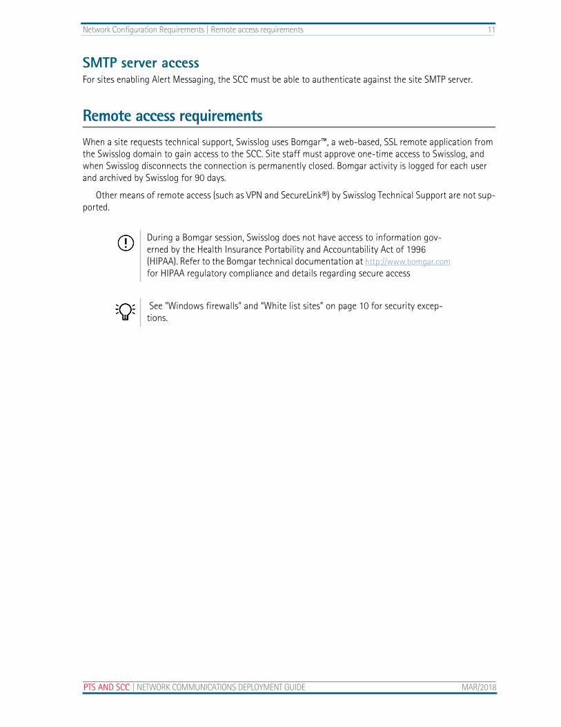
SMTP server accessFor sites enabling Alert Messaging, the SCC must be able to authenticate against the site SMTP server.
Remote access requirementsWhen a site requests technical support, Swisslog uses Bomgar™, a web-based, SSL remote application from the Swisslog domain to gain access to the SCC. Site staff must approve one-time access to Swisslog, and when Swisslog disconnects the connection is permanently closed. Bomgar activity is logged for each user and archived by Swisslog for 90 days.
Other means of remote access (such as VPN and SecureLink®) by Swisslog Technical Support are not sup-ported.
During a Bomgar session, Swisslog does not have access to information gov-erned by the Health Insurance Portability and Accountability Act of 1996 (HIPAA). Refer to the Bomgar technical documentation at http://www.bomgar.com for HIPAA regulatory compliance and details regarding secure access
See "Windows firewalls" and “White list sites” on page 10 for security excep-tions.
PTS AND SCC | NETWORK COMMUNICATIONS DEPLOYMENT GUIDE MAR/2018

12 Network Configuration Requirements | Remote access requirements
MAR/2018 NETWORK COMMUNICATIONS DEPLOYMENT GUIDE | PTS AND SCC

CHAPTER 3 Physical Server Specifications and Administration
PTS AND SCC | NETWORK COM
©2018 SWISSLOG HEALTHCARE. THIS DOCTRANSFER TO THIRD PARTIES IS PERMISSIBL
Settings, policies and configuration for workstations and servers
This chapter addresses the PTS specifications for applications and policies used by server administrators. These specifications apply to both physical and virtual machines.
Group policiesExclude the Swisslog PTS system from hospital IT group policies or create a new group policy that excludes the SCC from taking any downloads or updates. Do not override the SCC settings with the facility’s domain policies.
Windows updates and patchesSwisslog does not perform compatibility testing on Microsoft patches or updates. The site IT group is responsible for implementing Windows security updates during a scheduled PTS shutdown period to avoid computer automatic shutdown; the SCC requires a manual restart to bring the system back to an opera-tional state.
See “Virtual Server Specifications and Administration” on page 19 for additional settings applicable to virtualized environments.
Turn off Windows automatic updates.
MUNICATIONS DEPLOYMENT GUIDE MAR/2018
UMENT CONTAINS CONFIDENTIAL AND PROPRIETARY INFORMATION INTENDED FOR USE BY SWISSLOG AND ITS CUSTOMERS ONLY. E ONLY WITH THE WRITTEN CONSENT OF SWISSLOG. TRANSFER WITHOUT CONSENT MAY RESULT IN CIVIL PENALTIES.
14 Physical Server Specifications and Administration | Disk memory management
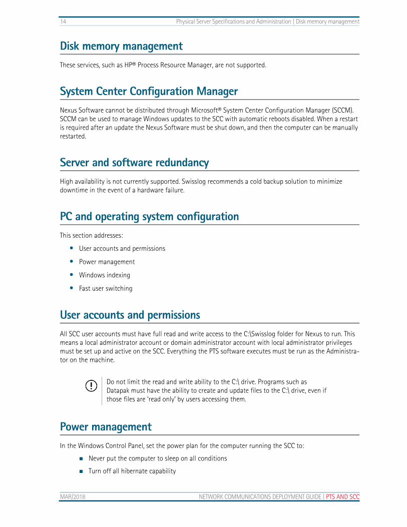
Disk memory managementThese services, such as HP® Process Resource Manager, are not supported.
System Center Configuration ManagerNexus Software cannot be distributed through Microsoft® System Center Configuration Manager (SCCM). SCCM can be used to manage Windows updates to the SCC with automatic reboots disabled. When a restart is required after an update the Nexus Software must be shut down, and then the computer can be manually restarted.
Server and software redundancyHigh availability is not currently supported. Swisslog recommends a cold backup solution to minimize downtime in the event of a hardware failure.
PC and operating system configurationThis section addresses:
• User accounts and permissions
• Power management
• Windows indexing
• Fast user switching
User accounts and permissionsAll SCC user accounts must have full read and write access to the C:\Swisslog folder for Nexus to run. This means a local administrator account or domain administrator account with local administrator privileges must be set up and active on the SCC. Everything the PTS software executes must be run as the Administra-tor on the machine.
Power managementIn the Windows Control Panel, set the power plan for the computer running the SCC to:
Never put the computer to sleep on all conditions
Turn off all hibernate capability
Do not limit the read and write ability to the C:\ drive. Programs such asDatapak must have the ability to create and update files to the C:\ drive, even if those files are ‘read only’ by users accessing them.
MAR/2018 NETWORK COMMUNICATIONS DEPLOYMENT GUIDE | PTS AND SCC
Physical Server Specifications and Administration | Windows indexing 15
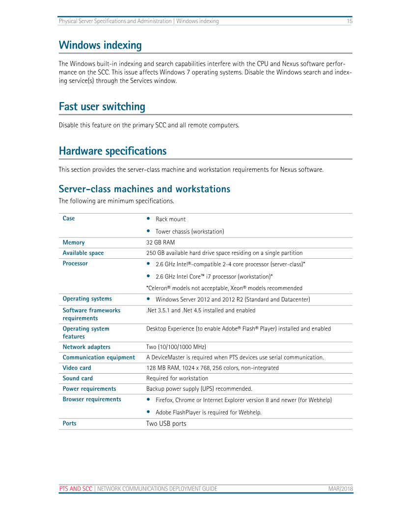
Windows indexingThe Windows built-in indexing and search capabilities interfere with the CPU and Nexus software perfor-mance on the SCC. This issue affects Windows 7 operating systems. Disable the Windows search and index-ing service(s) through the Services window.
Fast user switchingDisable this feature on the primary SCC and all remote computers.
Hardware specificationsThis section provides the server-class machine and workstation requirements for Nexus software.
Server-class machines and workstationsThe following are minimum specifications.
Case • Rack mount
• Tower chassis (workstation)
Memory 32 GB RAM
Available space 250 GB available hard drive space residing on a single partition
Processor • 2.6 GHz Intel®-compatible 2-4 core processor (server-class)*
• 2.6 GHz Intel Core™ i7 processor (workstation)*
*Celeron® models not acceptable, Xeon® models recommended
Operating systems • Windows Server 2012 and 2012 R2 (Standard and Datacenter)
Software frameworks requirements
.Net 3.5.1 and .Net 4.5 installed and enabled
Operating systemfeatures
Desktop Experience (to enable Adobe® Flash® Player) installed and enabled
Network adapters Two (10/100/1000 MHz)
Communication equipment A DeviceMaster is required when PTS devices use serial communication.
Video card 128 MB RAM, 1024 x 768, 256 colors, non-integrated
Sound card Required for workstation
Power requirements Backup power supply (UPS) recommended.
Browser requirements • Firefox, Chrome or Internet Explorer version 8 and newer (for Webhelp)
• Adobe FlashPlayer is required for Webhelp.
Ports Two USB ports
PTS AND SCC | NETWORK COMMUNICATIONS DEPLOYMENT GUIDE MAR/2018

16 Physical Server Specifications and Administration | Hardware specifications
Remote client specificationsThe following are minimum specifications.
Miscellaneous hardware • Keyboard
• Optical Mouse
• External speakers
• Dual 10/100/1000 GB Ethernet adapters
• UL Listed
Peripherals Any additional peripherals must be UL Listed.
Memory 2 GB RAM
Drives 10 GB available hard drive space
CPU 2.0 GHz Intel-compatible dual-core processor (Celeron models not acceptable)
Operating systems • Windows 7 Professional, Enterprise and Ultimate (all 64-bit)
• Windows 10 Professional, Enterprise and Ultimate (all 64-bit)
• Windows Server 2008 and 2008 R2 (Std, DataCenter and Enterprise)
• Windows Server 2012 and 2012 R2 (Std and DataCenter)
Video card 64 MB RAM, 1024 x 768, 256 colors, non-integrated
Sound card Required
Miscellaneous hardware (UL listed)
• Keyboard, optical mouse
• External speakers
• Cat 5 cable
• 10/100/1000 MHz Ethernet adapters
Remote clients are not supported in Citrix environments.
MAR/2018 NETWORK COMMUNICATIONS DEPLOYMENT GUIDE | PTS AND SCC
Physical Server Specifications and Administration | Hardware specifications 17
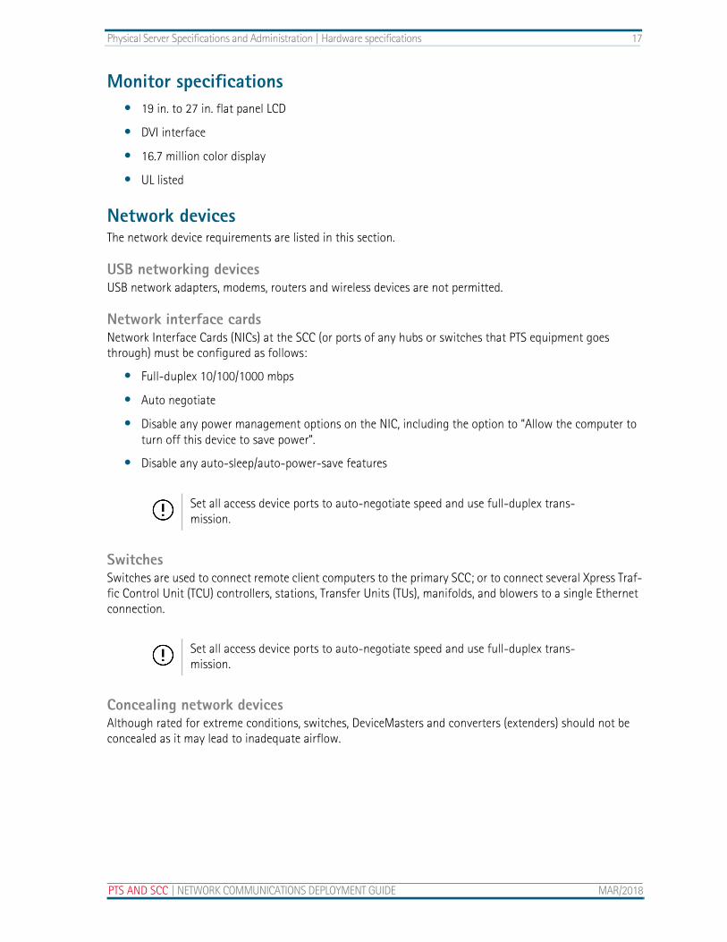
Monitor specifications• 19 in. to 27 in. flat panel LCD
• DVI interface
• 16.7 million color display
• UL listed
Network devicesThe network device requirements are listed in this section.
USB networking devicesUSB network adapters, modems, routers and wireless devices are not permitted.
Network interface cardsNetwork Interface Cards (NICs) at the SCC (or ports of any hubs or switches that PTS equipment goes through) must be configured as follows:
• Full-duplex 10/100/1000 mbps
• Auto negotiate
• Disable any power management options on the NIC, including the option to “Allow the computer to turn off this device to save power”.
• Disable any auto-sleep/auto-power-save features
SwitchesSwitches are used to connect remote client computers to the primary SCC; or to connect several Xpress Traf-fic Control Unit (TCU) controllers, stations, Transfer Units (TUs), manifolds, and blowers to a single Ethernet connection.
Concealing network devicesAlthough rated for extreme conditions, switches, DeviceMasters and converters (extenders) should not be concealed as it may lead to inadequate airflow.
Set all access device ports to auto-negotiate speed and use full-duplex trans-mission.
Set all access device ports to auto-negotiate speed and use full-duplex trans-mission.
PTS AND SCC | NETWORK COMMUNICATIONS DEPLOYMENT GUIDE MAR/2018
18 Physical Server Specifications and Administration | Cable requirements and specifications
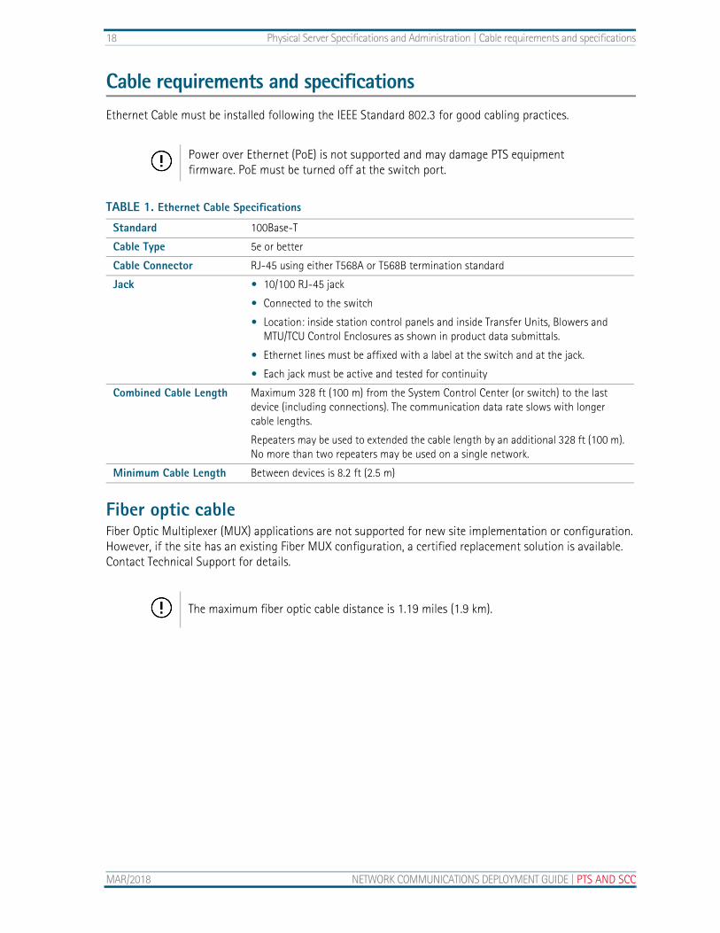
Cable requirements and specificationsEthernet Cable must be installed following the IEEE Standard 802.3 for good cabling practices.
Fiber optic cableFiber Optic Multiplexer (MUX) applications are not supported for new site implementation or configuration. However, if the site has an existing Fiber MUX configuration, a certified replacement solution is available. Contact Technical Support for details.
Power over Ethernet (PoE) is not supported and may damage PTS equipment firmware. PoE must be turned off at the switch port.
TABLE 1. Ethernet Cable Specifications
Standard 100Base-T
Cable Type 5e or better
Cable Connector RJ-45 using either T568A or T568B termination standard
Jack • 10/100 RJ-45 jack
• Connected to the switch
• Location: inside station control panels and inside Transfer Units, Blowers and MTU/TCU Control Enclosures as shown in product data submittals.
• Ethernet lines must be affixed with a label at the switch and at the jack.
• Each jack must be active and tested for continuity
Combined Cable Length Maximum 328 ft (100 m) from the System Control Center (or switch) to the last device (including connections). The communication data rate slows with longer cable lengths.
Repeaters may be used to extended the cable length by an additional 328 ft (100 m). No more than two repeaters may be used on a single network.
Minimum Cable Length Between devices is 8.2 ft (2.5 m)
The maximum fiber optic cable distance is 1.19 miles (1.9 km).
MAR/2018 NETWORK COMMUNICATIONS DEPLOYMENT GUIDE | PTS AND SCC
CHAPTER 4 Virtual Server Specifications and Administration
PTS AND SCC | NETWORK COM
©2018 SWISSLOG HEALTHCARE. THIS DOCTRANSFER TO THIRD PARTIES IS PERMISSIBL
System configuration settings to support Nexus Installations on a virtual machine (VM)
Nexus Software version 7.x can be installed on virtual machines for sites that meet the requirements and specifications listed in this section provided that the response time, I/O latency, and similar performance considerations are met by the virtual host on a level at, or exceeding, the equivalent performance of a dedi-cated, physical hardware server (as specified in this document).
VM requirements and specificationsThis section provides the minimum requirements a pneumatic tube system must meet to qualify for installa-tion on a VM and VM specifications.
MUNICATIONS DEPLOYMENT GUIDE MAR/2018
UMENT CONTAINS CONFIDENTIAL AND PROPRIETARY INFORMATION INTENDED FOR USE BY SWISSLOG AND ITS CUSTOMERS ONLY. E ONLY WITH THE WRITTEN CONSENT OF SWISSLOG. TRANSFER WITHOUT CONSENT MAY RESULT IN CIVIL PENALTIES.
20 Virtual Server Specifications and Administration | VM requirements and specifications
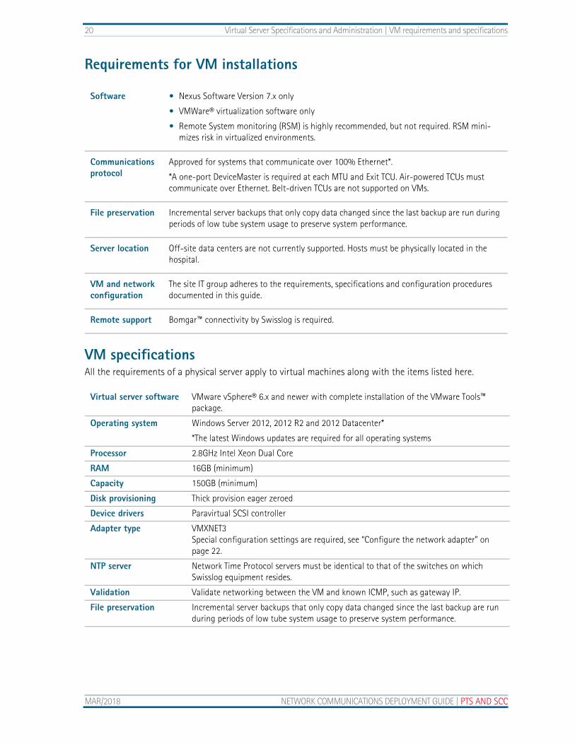
Requirements for VM installations
VM specificationsAll the requirements of a physical server apply to virtual machines along with the items listed here.
Software • Nexus Software Version 7.x only
• VMWare® virtualization software only
• Remote System monitoring (RSM) is highly recommended, but not required. RSM mini-mizes risk in virtualized environments.
Communications protocol
Approved for systems that communicate over 100% Ethernet*.
*A one-port DeviceMaster is required at each MTU and Exit TCU. Air-powered TCUs must communicate over Ethernet. Belt-driven TCUs are not supported on VMs.
File preservation Incremental server backups that only copy data changed since the last backup are run during periods of low tube system usage to preserve system performance.
Server location Off-site data centers are not currently supported. Hosts must be physically located in the hospital.
VM and network configuration
The site IT group adheres to the requirements, specifications and configuration procedures documented in this guide.
Remote support Bomgar™ connectivity by Swisslog is required.
Virtual server software VMware vSphere® 6.x and newer with complete installation of the VMware Tools™ package.
Operating system Windows Server 2012, 2012 R2 and 2012 Datacenter*
*The latest Windows updates are required for all operating systems
Processor 2.8GHz Intel Xeon Dual Core
RAM 16GB (minimum)
Capacity 150GB (minimum)
Disk provisioning Thick provision eager zeroed
Device drivers Paravirtual SCSI controller
Adapter type VMXNET3Special configuration settings are required, see “Configure the network adapter” on page 22.
NTP server Network Time Protocol servers must be identical to that of the switches on which Swisslog equipment resides.
Validation Validate networking between the VM and known ICMP, such as gateway IP.
File preservation Incremental server backups that only copy data changed since the last backup are run during periods of low tube system usage to preserve system performance.
MAR/2018 NETWORK COMMUNICATIONS DEPLOYMENT GUIDE | PTS AND SCC
Virtual Server Specifications and Administration | VM Administration 21
Clients in a VM environmentRemote clients are compatible with VMs when they meet the requirements listed in “Remote client specifi-cations” on page 16.
VM AdministrationIn addition to the network configuration and server administration requirements previously stated, the pro-cedures provided in this chapter are required for VMs to ensure proper data flow and resolve incompatibili-ties between Windows NIC options and VMXNET3 drivers.
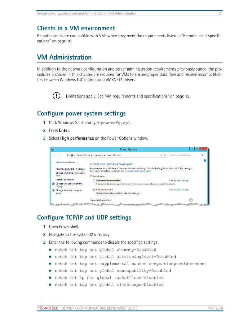
Configure power system settings1 Click Windows Start and type powercfg.cpl.
2 Press Enter.
3 Select High performance on the Power Options window.
Configure TCP/IP and UDP settings1 Open PowerShell.
2 Navigate to the system32 directory.
3 Enter the following commands to disable the specified settings:
netsh int tcp set global chimney=Disabled
netsh int tcp set global autotuninglevel=Disabled
netsh int tcp set supplemental custom congestionprovider=none
netsh int tcp set global ecncapability=Disabled
netsh int ip set global taskoffload=disabled
netsh int tcp set global timestamps=Disabled
Limitations apply. See “VM requirements and specifications” on page 19.
PTS AND SCC | NETWORK COMMUNICATIONS DEPLOYMENT GUIDE MAR/2018

22 Virtual Server Specifications and Administration | VM Administration
4 Enable receive-side scaling with the command netsh int tcp set global RSS=Enable
5 Validate the settings with the command netsh int tcp show global
6 Review the output to verify the settings were successfully applied.
Configure the network adapterFollow the procedures listed here to disable Internet Protocol version 6, power management and advanced properties for the network adapter.
Disable Internet Protocol version 6
1 Open the Network and Sharing Center.
MAR/2018 NETWORK COMMUNICATIONS DEPLOYMENT GUIDE | PTS AND SCC
Virtual Server Specifications and Administration | VM Administration 23
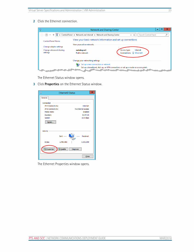
2 Click the Ethernet connection.
The Ethernet Status window opens.
3 Click Properties on the Ethernet Status window.
The Ethernet Properties window opens.
PTS AND SCC | NETWORK COMMUNICATIONS DEPLOYMENT GUIDE MAR/2018
24 Virtual Server Specifications and Administration | VM Administration
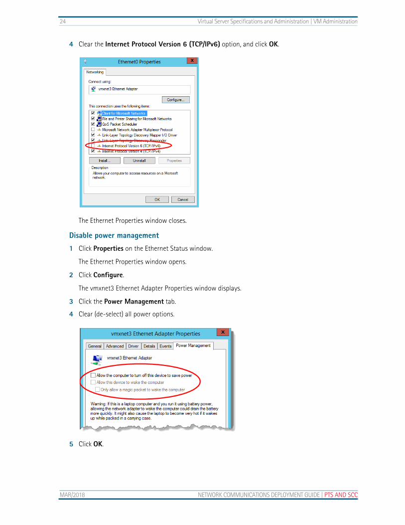
4 Clear the Internet Protocol Version 6 (TCP/IPv6) option, and click OK.
The Ethernet Properties window closes.
Disable power management
1 Click Properties on the Ethernet Status window.
The Ethernet Properties window opens.
2 Click Configure.
The vmxnet3 Ethernet Adapter Properties window displays.
3 Click the Power Management tab.
4 Clear (de-select) all power options.
5 Click OK.
MAR/2018 NETWORK COMMUNICATIONS DEPLOYMENT GUIDE | PTS AND SCC

Virtual Server Specifications and Administration | VM Administration 25
Modify the advanced settings
1 Click the Advanced tab on the vmxnet3 Ethernet Adapter Properties window.
2 Individually select each property listed below, and change its value to Disabled.
IPv4 Checksum Offload
IPv4 TSO Offload
Large Send Offload V2 (IPV4)
Large Send Offload V2 (IPV6)
Offload IP Options
Offload tagged traffic
Offload TCP Options
Recv Segment Coalescing (IPV4)
Recv Segment Coalescing (IPV6)
TCP Checksum Offload (IPv4)
TCP Checksum Offload (IPv6)
UDP Checksum Offload (IPv4)
UDP Checksum Offload (IPv6)
3 Click OK.
The Properties window closes.
PTS AND SCC | NETWORK COMMUNICATIONS DEPLOYMENT GUIDE MAR/2018

26 Virtual Server Specifications and Administration | VM Administration
MAR/2018 NETWORK COMMUNICATIONS DEPLOYMENT GUIDE | PTS AND SCC