switching fourth meeting. switching modes circuit switching continuous link exclusive packet...
TRANSCRIPT
Switching
Fourth Meeting

Switching Modes
Circuit Switching Continuous link Exclusive
Packet Switching No continuous link Data is divided into
packets Not exclusive
Circuit Switching` Packet Switching`
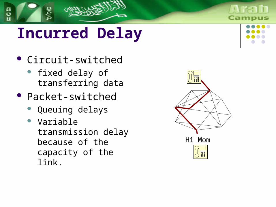
Incurred Delay
Circuit-switched fixed delay of transferring
data
Packet-switched Queuing delays Variable transmission
delay because of the capacity of the link. Hi Mom

Multiplexing It improve the efficient use of the transmission capacity of physical
media Two types of multiplexing
Deterministic Statistical
Deterministic Multiplexing transmission medium is divided between a fixed number of
communication channels

Statistical Multiplexing The multiplexer and demultiplexer do not perform any switching The multiplexer stores the incoming packets in a buffer. Why?
Data rates of the input channel and the multiplexed channel are different; and Packets may arrive simultaneously on several input channels.
In the multiplexer, the packets are stored with a header with input channel number.
In the demultiplexer, the packets are retrieved in reverse order The packet header identify the output channel. Buffers are required for each output channel
The demultiplexer, over a short period of time, receive packets at a faster data rate than it can transmit.

Switching Structures
Cross-points It connect input lines to output
lines with a dedicated cross-point
It is non-blocking Switching Arrays
single-stage switch connects one input line to an output line using a single cross-point

Three stage-switching Blocking occurs N inputs = m groups * n inputs N outputs = m groups * n outputs
The first stage m array switches. Each array switches
n input lines k output lines
The second stage k array switches Each array switch
m input lines m output lines
The third stage m array switches. Each array switches
k input lines n output lines
Switching Structures:3-Stage-Switching

How Many Cross Points The total number of cross-points =
number of cross-points in the first stage plus
number in the second stage plus number in the third.
First stage Total = n × k × m Since N = n × m, then Total = N × k
Second stage Total = k × m × m Since m = N/n, Then Total = k × (N/n)2.
Third stage (same as first stage) Total = N × k
All three stages .
22
2)()()(
n
NkNkkN
n
NkkNTotal

Three Stage Switching Example
6 input lines that is blocking. four first-stage arrays
m = 4 Each array hasfour input
lines n = 4
Five second-stage arrays k = 5
16 × 16 three-stage configuration has 240)165(160)
4
165()5162(
2

Digital Space Switching
Two types Digital space switching
and Digital time switching.
Digital space switching The first automatic
telephone exchanges Paths were set up using
electromagnetic devices

Space Switch Carries A Time Division Multiplexed (TDM)
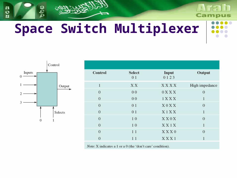
Space Switch Multiplexer

Space Switch Multiplexer

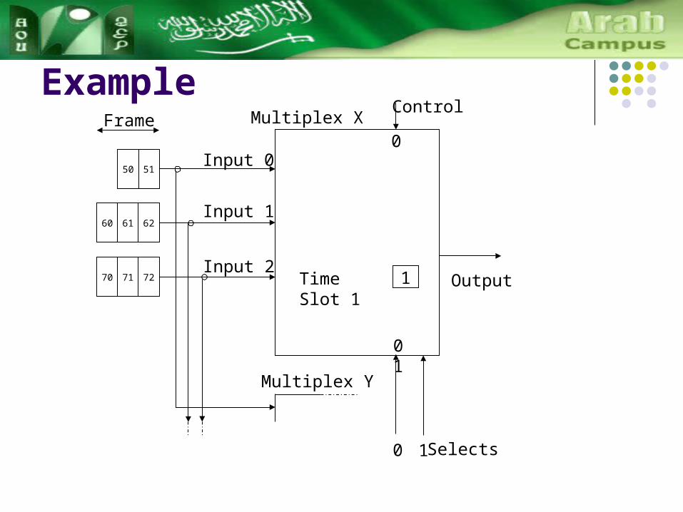
Example
727170
626160
525150Input 0
Multiplex X
Multiplex Y
Input 1
Input 2
Selects0 1
0 0
Control
0
Frame
Selects 0 = 0
Selects 1 = 0
Time Slot 0 Output
0
Example
727170
626160
5150Input 0
Multiplex X
Multiplex Y
Input 1
Input 2
Selects0 1
0 1
ControlFrame
1Time Slot 1 Output
0

Example
727170
6160
5150Input 0
Multiplex X
Multiplex Y
Input 1
Input 2
Selects0 1
1 1
ControlFrame
3Time Slot 2 Output
0

Example
727170
6160
5150Input 0
Multiplex X
Multiplex Y
Input 1
Input 2
Selects0 1
1 0
ControlFrame
2Time Slot 3 Output
0

Time Switching

Time Switching Implementation
Use two memory devices Speech store
All incoming data octets are stored in their sequence of arrival, Octet 0 → location 0 Octet 1 → location 1 : Cyclic counter
Connection store, Contains the destination
outgoing lines Has a cyclic counter

Example
0
0
3
01234 0
1234
Counter 1
Counter 20
Input Time Slot
Output Time Slot
0 3
1 2
2 1
3 4
0
Time

Example
01
1
32
01234 0
1234
Counter 1
Counter 21
Input Time Slot
Output Time Slot
0 3
1 2
2 1
3 4
0 1
Time

Example
012
2
321
01234 0
1234
Counter 1
Counter 22
Input Time Slot
Output Time Slot
0 3
1 2
2 1
3 4
0 1 2
Time

Example
0
23
3
3214
01234 0
1234
Counter 1
Counter 23
Input Time Slot
Output Time Slot
0 3
1 2
2 1
3 4
4 0
0 1 2 3
Time

Example
234
4
32140
01234 0
1234
Counter 1
Counter 24
Input Time Slot
Output Time Slot
0 3
1 2
2 1
3 4
4 0
0 1 2 3 4
Time

Space Time Space Switching
727170
6160
5150Input 0
Multiplex X
Multiplex Y
Input 1
Input 2
Selects0 1
1 0
ControlFrame
2Time Slot 3 Output
0
727170
6160
5150Input 0
Multiplex X
Multiplex Y
Input 1
Input 2
Selects0 1
1 0
ControlFrame
2Time Slot 3 Output
0
727170
6160
5150Input 0
Multiplex X
Multiplex Y
Input 1
Input 2
Selects0 1
1 0
ControlFrame
2Time Slot 3 Output
0
k = 1
n = 3
234
4
32140
01234
01234 0
1234
01234
Counter 1
Counter 24
72 71 70
61 60
51 50Input 0
Multiplex X
Multiplex Y
Input 1
Input 2
Selects 01
1 0
ControlFrame
2 Time Slot 3Output
0

Packet Switching In the past, the delay
associated with packet switching meant that it was not considered suitable for real-time applications such as voice communication.
Packet-switching exchanges (PSEs) have used the concept of stored program control (SPC) since the first generation of exchanges, in the late 1960s

2nd and 3rd Generation PSE

Cell Switching
Cell switching ≈ packet switching breaks a data stream into packets
Cell switching ≠ packet switching Cells have a fixed size
Cell switching ≈ circuit-switching connection-oriented service virtual circuit created.
Cell switching ≠ circuit-switching circuit is virtual No reserving of network resources
Virtual Path Switch 1
Virtual Path Switch 2
Picture source http://www.sce.carleton.ca/netmanage/dcommTutorials/scan06/scan0603.gif