synthesis and analysis of temporal fault trees with pandora: the time of priority and gates
TRANSCRIPT

Nonlinear Analysis: Hybrid Systems 2 (2008) 368–382www.elsevier.com/locate/nahs
Synthesis and analysis of temporal fault trees with PANDORA1: Thetime of Priority AND gates
Martin Walker, Yiannis Papadopoulos∗
Department of Computer Science, University of Hull, UK
Received 2 May 2006; accepted 30 May 2006
Abstract
Classical Fault Tree Analysis (FTA) can determine the effects of combinations of failure events on a system but cannot capturethe significance of the temporal order of events, which may be critical. In this paper, we propose an extension based on formaldefinition and use of Priority AND gates that enables representation of event sequences and analysis of temporal relationships inFTA. In addition, we show how this type of temporal analysis can be used in conjunction with a recently proposed method forautomated fault tree synthesis to allow accurate failure analyses of system models to be carried out efficiently. The approach isdemonstrated on a generic system with a shared backup component. The paper tentatively concludes that this type of temporal FTAcan provide a more precise and ultimately more correct insight into the failure behaviour of a system.c© 2006 Elsevier Ltd. All rights reserved.
Keywords: Safety analysis; Reliability analysis; Fault tree synthesis; Temporal fault trees; Temporal logic; HiP-HOPS
1. Introduction and background
Fault Tree Analysis (FTA) is a well established, widely used safety and reliability engineering technique whichwas originally developed in the 1960s to aid in the design of the Minuteman missile system. The technique definesan intuitive notation, which is easy to use and understand, and facilitates both quantitative and qualitative safety andreliability analyses. Fault trees themselves are graphical representations of logical combinations of failures, and showthe relationship between a hazardous failure and the events that cause it. A fault tree normally consists of a top event,which is typically a hazardous system failure, connected to one or more basic events via a system of logical gates,such as AND and OR. Basic events are typically either failures of individual components or the effects of externalfactors on the system, but can also be events that are part of the normal operation of the system.
Analysis of the fault tree consists of two parts: qualitative (logical) analysis, and quantitative (probabilistic)analysis. Qualitative analysis is done by reducing the logical expression represented by the fault tree into a set ofminimal cut sets, which are the smallest possible combinations of failures required to cause the top event. Quantitative
∗ Corresponding author.E-mail addresses: [email protected] (M. Walker), [email protected] (Y. Papadopoulos).
1 PAND-ORA: Hour or “time” (ORA [ωρα] in Greek) of PAND gates.
1751-570X/$ - see front matter c© 2006 Elsevier Ltd. All rights reserved.doi:10.1016/j.nahs.2006.05.003

M. Walker, Y. Papadopoulos / Nonlinear Analysis: Hybrid Systems 2 (2008) 368–382 369
analysis is done by calculating the probability of the top event given the probability of each of the basic eventsoccurring.
Over the years, it has become apparent that FTA has a number of drawbacks, some of which are common to mostsystems analysis methodologies, and some of which are unique to FTA itself. Of the former, one major drawback ofFTA is that it remains primarily a manual method; the same is true of other analysis techniques, like FMEA (FailureModes and Effects Analysis), HAZOPS (Hazard and Operability Studies), and event trees. Whilst this has the benefitof providing the analyst with an in-depth knowledge of the system being studied, it means that undertaking an FTAis often both time consuming and, for larger systems, prone to errors. As a result, it is not uncommon for FTA totake place only once or twice in the life cycle of the system. This is unfortunate, because systems analysis techniqueslike FTA can be of great benefit during an iterative design process. By estimating the reliability and gaining a morethorough understanding of the failure behaviour of the system in each iteration, it is be possible to see how the changesin design impact upon the overall safety of the system. It also enables the analysts to identify and remedy potentialflaws much earlier, thereby saving both time and effort and producing a more reliable product. However, before FTAcan be incorporated into the design cycle in this way, it is necessary to overcome the problems inherent in such amanual technique. The best way of doing this would be to automate FTA in some way, or at least enable parts of theprocess to be carried out in an automated fashion. This would mean that the analysis could be carried out more quicklyand efficiently.
HiP-HOPS (Hierarchically Performed Hazard Origin and Propagation Studies) is a recently proposed techniquefor the semi-automatic construction of fault trees and FMEAs intended to achieve such a goal [1]. By annotatingthe system model with expressions describing the failure behaviour of individual components, HiP-HOPS can thenexamine the model and automatically construct and analyse both fault trees and FMEAs. The result is a semi-automated process which takes much of the burden off the system designer and speeds up the analysis considerably,allowing the designer to quickly identify weak points in the model and take steps to remedy them.
As mentioned before, however, there are also some problems specific to FTA, and by extension, HiP-HOPS suffersfrom them too. One particular criticism of classical FTA is that, despite evolving over the years, it still struggles toadequately analyse systems in which the temporal order or timing of events plays an important part in the failure ofthe system. This can include phased-mission systems, in which the operation (and therefore the failure behaviour)of the system differs according to which mode the system is in; systems with redundant or standby components, inwhich the behaviour of the system adapts to the occurrence of a fault; and also systems in which events must occur ina certain sequence in order to cause a fault. In such cases, the analysis usually either involves creating multiple faulttrees to model each mode of operation, or enclosing the temporal constraints directly within the event descriptionsthemselves. Neither of these approaches are really satisfactory: the first leads to complex, fragmented analyses, andthe second effectively excludes important temporal information from the logical structure of the fault tree.
This problem is not new. Indeed, one of the earliest solutions to this issue was the Priority-AND (or PAND) gate,as described in the Fault Tree Handbook [2], which would evaluate to true only if all of its inputs occurred in a specificorder, typically from left to right. There was even some work done to enable quantitative analysis of PAND gates byFussel et al. and later by Long and Sato [3–5]. Despite this, the gate’s semantics were never rigorously defined; whenit is used at all, it tends to be treated effectively as an AND gate rather than a unique logical gate, particularly inqualitative FTA. The implications of this are explained in Section 3.
In more recent times, however, there have been other attempts to remedy this temporal deficiency in FTA. Thereare several different “Dynamic Fault Tree” (DFT) methodologies available, such as the version proposed by Cepinand Mavko for use in Probabilistic Safety Assessment [6] and another style by engineers at Relex Software [7], butprobably the most prominent DFT approach is that of Dugan, Sullivan and Coppit at the University of Virginia [8,9]. Its goal is to enable fault trees to analyse systems with more complex dynamic interrelationships between events,including functional dependencies, standby components, and event sequences. DFTs define a set of new gates tomodel these additional relationships, and the resulting fault tree is then solved using a combination of Markov chainsand traditional static techniques such as Binary Decision Diagrams (BDDs). This is done by dividing the tree intomodules, which are independent sub-trees, according to the Linear Time algorithm proposed by Dutuit and Rauzy [10,11]. Modules containing new dynamic gates are subjected to Markov analysis, and modules containing only traditionalstatic gates are analysed using BDDs.
The set of temporal gates proposed by Palshikar takes a different approach [12]. Rather than concentrating onextending fault trees to account for different states of operation, with spare components and sequential dependencies,

370 M. Walker, Y. Papadopoulos / Nonlinear Analysis: Hybrid Systems 2 (2008) 368–382
TFTs concentrate on more generic temporal information. They retain the standard fault tree structure but add newgates (such as ‘within’, ‘sometime’, and ‘prev’) to represent various temporal relations; in addition, techniques areprovided for qualitative analysis of TFTs, including two algorithms to obtain cut sets.
At the opposite end of the spectrum to DFTs and TFTs is the simple TAND connective. In their paper, Wijayarathnaand Maekawa [13] study the Priority-AND gate and find it to be insufficiently defined. Instead, they propose anAND–THEN gate (TAND) to replace it. The TAND gate has strictly defined semantics and, in combination with atemporal version of the AND gate, it is able to precisely represent many temporal relations. It is intended to serve as auseful replacement for the Priority-AND gate, but it is much more specific in scope: it represents the situation whereone event occurs immediately after another (thus the term ‘and–then’). The TAND gate can also be used as a buildingblock to represent more complex temporal relations.
Whilst each of these various solutions has advantages, each also has disadvantages. DFTs are useful for modellingsituations involving dynamic behaviour, which include functional dependencies and standby components. However,DFTs were conceived as a quantitative solution, and lack a general method for performing qualitative analysis. TFTsare more general in application and provide for qualitative analysis, but they are quite complex and introduce manynew gates to the fault tree. Lastly, though the TAND gate is designed to be both flexible and independent of anyparticular representation of time, it is somewhat limited by its narrowly defined scope, as will be explained in Section 3.FTA is widely-used because it is intuitively understood and easy to apply, equally capable of providing qualitativeinformation as well as quantitative calculations. Burdening the fault tree structure with too many new gates or limitingits application too far begins to go against the original philosophy that makes FTA popular.
In this paper, we look at a different approach that employs a redefinition of the original long-established Priority-AND gate to represent the temporal information in a fault tree, and a new way of qualitatively analysing thisinformation automatically, as part of HiP-HOPS, using a novel decompositional technique called ‘doublet analysis’.The intent behind this work is to provide a simple yet flexible method for performing qualitative analysis on temporalfault trees.
In Section 2, we explain what the HiP-HOPS tool does and how it works. In Section 3, we discuss the redefinitionof the PAND gate and the temporal logic it is intended to represent. In Section 4, we present the temporal analysisand reduction methods used to simplify temporal expressions in the fault trees. Section 5 explains the principlesbehind doublet analysis, a new way of logically reducing the number of cut sets obtained. In Section 6, we presentan example to show how the algorithms are meant to be employed, and finally, in Section 7 we draw conclusions andoutline further work.
2. HiP-HOPS
The HiP-HOPS fault tree synthesis (FTS) tool works on architectural models produced during the design process.Such models must identify components and the material, energy or data transactions among those components. Byannotating the model with data describing how individual components can fail, the FTS tool can then take that data andproduce a series of fault trees from it. From those trees it can generate a wealth of reliability information, presentedin the form of an FMEA table and/or viewable fault trees.
At present, the tool is being developed for use with two different modelling tools, Matlab Simulink and SimulationX. Both versions of the tool allow a model of a system to be loaded and parsed. Once this internal representation ofthe model has been loaded, the tool synthesizes fault trees for every system failure in the model and combines themto create the FMEA. During this process, analysis of the fault trees is carried out: the minimal cut sets are obtained,and the unavailability, or probability, of the top event is also calculated. These results are integrated into the resultantFMEA tables, which are presented in the form of hyperlinked web pages. This format allows the designer to locate aspecific failure and click on it to find the effects it has on the rest of the system.
HiP-HOPS analysis consists of three main phases. The first phase consists of annotating the system model withthe failure data needed to produce the fault trees and perform the analysis. Before any fault trees can be generated,the tool needs to know how the various components of the system are interconnected, and how each one can fail. Thestructural data is provided by the model itself, which shows the basic topology of the system and the connectionsbetween the various components and subsystems. The models can also be hierarchically arranged, so that systemscan be decomposed into subsystems which each have their own components. The types of models which the FTS

M. Walker, Y. Papadopoulos / Nonlinear Analysis: Hybrid Systems 2 (2008) 368–382 371
tool can be applied to are varied; fluidic systems, electrical or electronic systems, mechanical systems, and even moreconceptual data flow based models are all suitable, as long as they can be augmented with failure data.
The failure data is what needs to be entered separately; each component or subsystem needs its own local failuredata, which describes what can go wrong with that component and how it responds to failures elsewhere in the system.This is achieved by annotating the model with a set of failure expressions showing how deviations in the componentoutputs (output deviations) can be caused either by internal failures of that component (which become basic events)or corresponding deviations in the component’s inputs. Such deviations include unexpected omission of output orunintended commission of output, or more subtle failures such as incorrect output values or the output being too earlyor late. This logical information describes all possible deviations of all outputs of a component, and so provides adescription of how that component fails and reacts to failures elsewhere. Once done, the data can then be stored in alibrary, so that other components of the same type can use the same failure data. This avoids the designer having toenter the same information many times.
At the same time, numerical data can be entered for the component, detailing the probability of internal failuresoccurring and the severity of output deviations. These data will then be used during the analysis phase to arriveat a figure for the unavailability of each top event. Other information can be added at this stage to facilitate moreadvanced analysis, including the option to enter information for different implementations of a component to allow anoptimization algorithm to determine the most efficient choice of component to use, and the addition of temporal data,to describe more complicated failure behaviour.
In the second phase, the FTS tool uses the local descriptions of component failure behaviour and the structureof the model (i.e. components and their material, energy or data transactions) to generate fault trees that provide aglobal view of failure behaviour of the system. These fault trees show how the component failures specified in localexpressions propagate through connections in the system model and cause functional failures at system outputs. Thefault trees may share branches and basic events, since one component may cause a failure in more than one location.Such basic failures are then common causes, since they can contribute to more than one system failure. Commoncause failures are generally especially vulnerable points in a system.
There is additional work undertaken in the synthesis phase to deal with a variety of special circumstances, suchas circular paths in the model which create circular failure logic in the fault trees. Such loops are incorporated onlyonce, with a special node at that point in the tree indicating the prior existence of circular logic there. It also handleshierarchical models, so that a subsystem can have both its own failure data in addition to the failure data of itssub-components (known as horizontal and vertical failure data, respectively). That way, the individual failures ofthe components that make up the subsystem are fully represented, but at the same time failures that affect the wholesubsystem (e.g. environmental disturbances, such as electromagnetic interference) can be represented at the subsystemlevel rather than repeated in each sub-component. Generally, the FTS tool will combine these two sets of failure datawith an OR gate, so that the occurrence of either one is enough to cause the subsystem to fail.
In the final phase, the synthesized fault trees are analysed, both qualitatively and quantitatively, and from theseresults the FMEA is created. Firstly, the fault trees undergo qualitative analysis to obtain their minimal cut sets,which reduces them in size and complexity. This is done using a mixture of classical logical reduction techniques,i.e. application of logical rules to reduce complex expressions, and more modern techniques, such as the use of BinaryDecision Diagrams (BDDs) [14] to break down the tree into a simpler form. BDDs are graphs that represent the pathsof failures through the fault tree, and are much faster and more efficient than classical methods, but unfortunately theycannot be used in all situations.
Once the minimal cut sets have been obtained, they are analysed quantitatively, which produces unavailabilityvalues for the top events of each fault tree. At present, this is done using a single formula that represents only constantfailure rates, but there are many other formulae available that we hope to incorporate in the future.
The last step is to combine all of the data produced into an FMEA, which is a table that concisely illustrates theresults. The FMEA shows the direct relationships between component failures and system failures, and so it is possibleto see both how a failure for a given component affects everything else in the system and also how likely that failureis. However, a classical FMEA only shows the direct effects of single failure modes on the system, but because of theway this FMEA is generated from a series of fault trees, the FTS tool is not restricted in the same way, and the FMEAsproduced also show what the further effects of a failure mode are — the effects that the failure has on the system whenit occurs in conjunction with other failure modes.

372 M. Walker, Y. Papadopoulos / Nonlinear Analysis: Hybrid Systems 2 (2008) 368–382
In the future, it is hoped that this information can then be used to automatically optimize the design, by choosingthe most efficient components to be used and by replicating them where extra redundancy is required. Of course, suchextra functionality will always require extra data to be provided in the annotation phase. The research discussed inthis paper, however, is focused on how to enable HiP-HOPS to handle temporal fault trees.
3. PAND gates
The Priority-AND (PAND) gate is one of the more obscure types of gate available to the fault tree analyst. It is notnew, but it is rarely used and poorly understood. The PAND gate is a modified version of the AND gate intended torepresent situations where the order of events is important: it is true if all of its inputs are true (like the AND), butonly if they occur in a certain order. For two inputs, one has a higher priority than the other, and must occur first —hence the name. In this, it is unique amongst the standard gates, because by enforcing an order upon a set of events, itintroduces the notion of time to the fault tree. The PAND gate does not just represent a subset of the behaviour of theAND gate, it is a means of representing time-based information and sequences of events in fault trees.
PANDs are a simple but effective way of representing the temporal aspect of failure behaviour, and so it is notsurprising that they have been part of the fault tree toolbox for decades. The problem with the PAND, however, wasthat it was never properly defined, meaning it was difficult to use it in qualitative analysis. In addition, no cut setalgorithm seems to have attempted to take PAND gates into account (though the same is often true of any gate otherthan the AND and OR gates). Those cut set analysis algorithms that do recognise it at all, such as SETS [15], simplytreat the PAND gate as a normal AND gate for the purposes of logical reduction.
It is not surprising that the difficulties with the gate’s lack of a rigorous definition mean it is seldom used, becausethe ambiguous nature of the gate raises a number of questions. The PAND gate is true if its inputs occur in a set order,but what if two of the events occur at the same time? Should it be limited to just two inputs, or can it take any number?Which order are the events supposed to occur in? How do we define whether one event occurs before another? Whatif the first event lasts long enough to overlap the second event? Admittedly, not all of these questions stem from thePAND gate itself; much depends on our definition of time.
There are many different ways of thinking about time. One of the first distinctions made is between absolutetime, which functions on dates and timings, and relative time, which functions more on comparative measurements.Relative time allows imprecision in that it is not necessary to know the exact time when an event occurred, justwhether it occurred before or after another event (e.g. “last year”). Absolute time, by contrast, is much more accurate:it describes exactly when an event occurred (e.g. 2:20 a.m., 15th April 1912). Since, in fault trees, it is unknownexactly when a fault will occur (indeed, it may never occur), it is more valuable to work with sequences of events,rather than timings, and relative time lends itself more readily to this purpose than absolute time does, at least for themajority of situations.
Another variation, more philosophical this time, is between linear time and branching time. With linear time, timeis represented by a single timeline, but with branching time, there can be multiple paths in both the future and the past,and events cause different timelines to split from the original line (e.g. in one path the event was true, in the other theevent was false). One further point to note here is the notion of bounds. A linear time model can be bound in the past(i.e. it has a fixed starting point), bound in the future (it has an end point), both, or neither. Similarly, branching timecan branch only in the future, only in the past, or both.
There are also versions of time in which events are persistent or not, in which time is represented as a continuoustimeline (like real numbers) or a discrete timeline (like integers), and as if those weren’t enough, there is onemore possible distinction. This division is between point-based systems of time and interval-based ones. Point-basedsystems represent time as a series of discrete moments, and periods of time are therefore defined as collections of thesepoints. Interval-based systems divide a continuum of time into tiny intervals, in the same way we divide up minutesinto seconds, which can then be used to create larger intervals. The problem arises when we look at the interfacebetween periods of time; in a point-based system, we have two choices: either the two periods share a single point intime, at which point they seem to overlap, or the second period begins at the next point in time after the first ends, inwhich case there appears to be a gap between them. With interval-based systems, the problem is one of resolution —how small do the intervals need to be? What happens when these intervals meet? There are also many more ways fortwo intervals to interact than two points — they may overlap, or one may contain the other, or they may be entirelyseparate.

M. Walker, Y. Papadopoulos / Nonlinear Analysis: Hybrid Systems 2 (2008) 368–382 373
Fig. 1. The meaning of the TAND gate.
Fig. 2. Using the TAND as a building block.
The TAND gate (symbol: Π ) was specifically designed to try to address this issue. The TAND (or And–Then) gateis true if and only if its first input occurs immediately before its second input. This is best visualized using a timeline,like in Fig. 1.
By representing this specific ‘and–then’ temporal relation, it is possible to use the TAND gate (and a redefined ANDgate, representing the situation where A and B overlap exactly) to represent virtually any other temporal relation [16].For example, if we wanted a gap between A and B, as in Fig. 2, we can use the TAND gate to connect the values ofthe two events at each stage:
(A.¬B)Π (¬A.¬B)Π (¬A.B).
This solves the problem of the ambiguity that plagues that PAND gate, and allows us to precisely represent relativetemporal ordering, but it is a very basic approach that requires the analyst to represent more general situationsusing complex combinations of TAND gates, standard logical gates, and negated events. Introducing inverted events(i.e. NOT gates) to fault trees can have a profound effect on the fault tree [17], and even simple operations (likethe “After” relation shown above) are quite complex. More fundamentally, though, the TAND gate inadvertentlyintroduces a new problem: by linking the TAND gate to one particular temporal relation and therefore one particularrepresentation of time, the TAND gate becomes less flexible and less compatible with other representations of time— something that the TAND gate was originally intended to avoid. The difficulty arises from the fact that the TANDgate implicitly uses a model of time in which events have clearly defined starting points, end points, and durations. Soalthough the TAND gate is largely independent of whether it is representing a point-based or interval-based systemof time, and can represent both relative and absolute models of time, it effectively requires each event to have a finiteduration. However, the Fault Tree Handbook says both that “from the standpoint of constructing a fault tree, we needconcern ourselves only with the phenomenon of occurrence”, and “under conditions of no repair, a fault that occurswill continue to exist”. Effectively, in fault trees, events do not have durations; once they occur, they are always true.As a result, the TAND gate does not accurately represent the way fault trees work (since it is not possible for oneevent to “meet” another event under that definition), and this raises questions about the suitability of the TAND gatefor use in FTA.
What is needed, we believe, is a more general temporal gate that is not restricted in such a way; one that can workwith a relative representation of time, yet is still sufficiently well-defined to enable it to be analysed appropriately. Atits core, this is exactly what the Priority-AND gate was intended to do — it was designed to show simply whether oneevent occurred before another, so that it could impose a sequence on a set of events. By taking this original purposeand focusing it, it is possible to transform the original, ambiguous PAND gate into a more effective temporal gate.One thing that all representations of time have in common, by definition, is that they must be capable of distinguishingwhether one moment in time is the same as another moment in time. If not, then one or the other must come first. If wetake this fundamental definition and apply it to the Priority-AND gate, we avoid many problems inherent in becomingbound to a specific definition of time. Instead, we say that a PAND gate is only true if its first (leftmost) input occursany time before its second input.
Furthermore, we can take the moment of time in question to be the moment at which an event first occurs. Weignore any duration it may or may not have and effectively assume that once it is true, it remains true for all time, inkeeping with the definition of events in fault trees. This vastly simplifies both the representation and the analysis, andavoids many problems with overlaps and indefinite intervals of time. Lastly, we limit ourselves to considering onlysingle occurrences, not repeating events. Repeating events are much harder to deal with because they introduce thepossibility of an event occurring both before and after another event. Since in FTA the events in question are mostlycomponent faults, it seems reasonable to limit ourselves in this way because the only way such fault can repeat is if

374 M. Walker, Y. Papadopoulos / Nonlinear Analysis: Hybrid Systems 2 (2008) 368–382
there are mechanisms of self-correction and repair. If such mechanisms exist, then every separate instance of a failurefollowing a repair must be modelled as a separate event in the fault tree.
This means that the PAND gate can now work with both relative and absolute systems of time, as well as bothpoint- and interval-based representations, since all that is required is to know whether or not an event occurred beforeanother. If we then have another gate, which is a temporal version of the classical AND gate that represents thesituation where two moments in time are the same, we can then represent all possible situations for two events, A andB, as follows:
(1) A < B — A is before B(2) A&B — A is at the same time as B(3) A > B — A is after B.
We define the symbols ‘<’ and ‘>’ intuitively to mean ‘occurs before’ and ‘occurs after’ respectively, and the symbol‘&’ to mean ‘occurs simultaneously’. Having described our definition of time, it is now possible to describe thedefinitions of our two temporal gates:
Name: Simultaneous-AND (SAND) gateSymbol: &Temporal value: When A&B is true, t (A&B) = t (A) = t (B)
Meaning: B occurs at the same time as A occurs. Both A and B must occur.
The requirement for this ‘temporal AND gate’ was also identified by Wijayarathna et al. during the developmentof the TAND gate. It is important here because it succinctly represents the second of our three fundamental temporalrelations. The other gate is, of course, the PAND gate:
Name: Priority-AND (PAND) gateSymbol: <
Temporal value: When A < B is true, t (A < B) = t (B)
Meaning: B occurs at some point in time after A has occurred. Both A and B must occur.
The PAND gate is designed to show the order in which events occur, but unlike the TAND gate, there is no notion ofduration with the Priority-AND gate. The PAND gate’s only purpose is to show the sequence of events, regardless ofwhether they occur immediately after one another or whether they occur years apart. The ability to define a meaningfulrelative temporal relationship between two events without reference to the unspecified time interval between thoseevents is the greatest strength of the PAND gate, but also perhaps the main reason why the gate has hitherto not beenthoroughly defined. Lastly, it is useful to note the ‘temporal value’ of the two gates. The temporal value of an eventor gate is the time at which it occurs (and so becomes true). For gates, this is the value of time that is used when onegate is an input to another gate. For example, if we had the expression (A < B)&C then the Priority-AND gate is trueonly when both A and B have occurred, as long as B occurs last. Because of this, the PAND gate becomes true at thesame time as B becomes true, and so t (A < B) = t (B). The Simultaneous-AND gate is then true only if the PANDgate is true at the same time as C occurs — t (PAND&C) = t (C) = t (PAND), and therefore only true if B and Coccur simultaneously. Note that the classical logic gates, such as AND and OR, have undefined temporal values; foran AND gate, it is impossible to know which of its inputs came last, and for an OR gate, it is impossible to knowwhich of its inputs came first.
With these newly defined temporal gates, it is possible to see how they might enhance the expressive power of faulttrees. Since there are three possible temporal relations between two moments in time, and all can be represented usingour two temporal gates, it should be possible to represent any combination of events – or order of events – in a faulttree. For two events A and B, both true, either they occur simultaneously or one must occur before the other, and onlyone of these three situations can be true at any time. However, if we want to use these gates for qualitative analysis,we need to have ways of logically reducing them.
4. Temporal analysis
Logical reduction is carried out by substituting small expressions for equivalent larger expressions according to aset of rules that tells us whether a substitution is valid or not. Boolean laws like the Idempotent and Absorption lawsallow us to simplify the logical expressions and therefore make them easier to understand.

M. Walker, Y. Papadopoulos / Nonlinear Analysis: Hybrid Systems 2 (2008) 368–382 375
Qualitative temporal analysis of the new temporal gates functions in exactly the same way: by using a set oftemporal laws to reduce complex expressions into simpler ones. Classical Boolean laws of reduction still apply inmany cases if an AND operator is substituted for a PAND or a SAND, because both temporal gates represent subsetsof the AND gate. For example, if we have an expression such as A+ A < B, then the PAND gate is redundant, and weare left with just A. Similarly, a duplicated temporal gate in a cut set is redundant (e.g. A < B + A < B = A < B).However, it important to realize that not all of the traditional Boolean laws apply to PAND and SAND gates. Indeed,these differences are the source of several temporal laws.
The first such law is derived from our definition of time as described above, which means that only one temporalrelationship is true at any one time:
(X < Y ).(Y < X) = 0
(X < Y ).(X&Y ) = 0
(Y < X).(X&Y ) = 0.
We name the above the Laws of Mutual Exclusion. They simply state that only one temporal relation is possible ata time, and therefore it is not possible for both X to occur before Y and for Y to occur before X , or for X to occurbefore Y and X to occur at the same time as Y . If these situations occur, the whole branch is redundant.
Second, the PAND gate is not subject to the Idempotent Law: X < X does not equal X . This is due to the waywe have defined our PAND gate to mean that its first input must follow its second. To explain this, consider tX to bethe time of event X , and tY to be the time of event Y . It is easy to see that X < Y is true if both X and Y occur andtX < tY . If X < X is assumed to be true, it would mean that X must occur and tX < tX , which is impossible, henceX < X is false (proof by contradiction). The Idempotent Law does apply to the SAND gate, though, and from thesefacts we get the Laws of Simultaneity:
(X < X) = 0, (X&X) = X.
As mentioned earlier, both the PAND and the SAND gates represent subsets of the AND gate, meaning that any timea PAND or SAND gate is true, an AND gate will also be true (but not vice versa). This is described by the Law ofCompletion:
X.Y = (X < Y ) + (X&Y ) + (Y < X).
It is so called because it takes all three temporal relations to complete the AND gate. It is important to note, however,that due to the Law of Mutual Exclusion, only one of these three temporal relations can be true at any point; i.e. forX.Y , either tX < tY , tX > tY or tX = tY .
Another law, which we call the Law of Extension, shows how PAND gates with more than two inputs behave.
X < Y < Z = (X < Y ).(Y < Z) = (X < Y ).(Y < Z).(X < Z).
The name of the law comes from the fact that if we have two PAND gates (X < Y ) and (Y < Z) connected by anAND gate, then by extension there must be an implicit third term (X < Z). It has several important consequences.First, it shows how we can expand multiple input PAND gates. But furthermore, it shows that events can gain extratemporal information without it being explicitly shown. Logically, this is quite clear: if X is before Y , and Y is beforeZ , then X must also come before Z .
This fact is very important in detecting cyclic redundancies. A cyclic redundancy is the trickiest temporalredundancy to detect, and it only occurs when multiple PAND gates are combined by an AND, such as:
(X < Y ).(Y < Z).(Z < X).
Clearly, if we try to combine these into a single PAND gate, we get a contradiction: X < Y < Z < X . By using theLaw of Extension, we can detect this situation; first, we can generate an extra term from (X < Y ).(Y < Z):
(X < Y ).(Y < Z).(Z < X).(X < Z).
Then, from the Law of Mutual Exclusion, we know we have encountered an impossible situation, because we haveboth (Z < X) and (X < Z).

376 M. Walker, Y. Papadopoulos / Nonlinear Analysis: Hybrid Systems 2 (2008) 368–382
The Law of Extension also means that X < Y and X < Z cannot be combined into X < Y < Z (unless thethird term Y < Z is also present), because the temporal relation between Y and Z is not apparent. Of course, theLaw applies to any number of events, not just three, but the more events used, the larger the resulting number ofterms. Breaking down W < X < Y < Z into composite terms without applying extension leads to just three terms(W < X, X < Y , and Y < Z ); applying the law gives six (the extra three are W < Y , W < Z , and X < Z ). Indeed,it can be shown that without the Law, (N − 1) terms are produced, but using it produces 1/2N (N − 1) terms. As aresult, for larger compound PAND gates (i.e. a PAND containing many child events, all of which are leaf nodes), it issimpler just to check to see whether any event appears more than once, at which point the gate is redundant; however,this situation is rare.
Another Boolean law that functions differently for temporal gates is the Law of Absorption. For both SAND andPAND gates, applying this law gives us:
X.(X < Y ) = X < Y
X.(X&Y ) = X&Y.
The reason for this is due to the fact that the temporal gates introduce extra information (which we call temporalsignificance) to their input events, in this case X and Y . Because of the fact that PAND and SAND gates are subsetsof the AND, any time X < Y or X&Y is true, X must also be true, but the same is not true in reverse (i.e. if X is true,X < Y is not necessarily true).
The Distributive Law also functions differently when applied to expressions containing both types of temporalgate. When the PAND and SAND gates are mixed, the results can be surprising:
X < (Y &Z) = (X < Y ).(X < Z).(Y &Z)
X&(Y < Z) = (X&Z).(Y < Z).(Y < X).
The first expression expands as we would expect, except that we obtain a third term from the Law of Extension (ifX is before Y , and Y is at the same time as Z , then by extension, X must also be before Z ). The second expression,however, is strange, because we get two PAND gates and only one SAND gate. The reason for this is due to thetemporal values of the respective gates. We know from our definition of the PAND gate that t(Y<Z) = tZ .
The temporal information we get from the expression is therefore:
tY < tZ , t(Y<Z) = tZ , and tX = t(Y<Z) = tZ .
If tX = tZ and tY < tZ then tY must also be less than tZ , which gives us the result: (X&Z).(Y < Z).(Y < X). Thesituation is not simple even when we mix two PAND gates together, because the PAND does not obey the AssociativeLaw; i.e.
X < (Y < Z) 6= (X < Y ) < Z
6= (X < Y ).(X < Z).(Y < Z).
In other words, X < Y < Z is not the same as X < (Y < Z). The reason for this is that the temporal value of(Y < Z) is tZ , and so all we know is that tX < tZ . Therefore, X < (Y < Z) is actually equivalent to (X.Y ) < Z .Fortunately, the SAND gate obeys the Associative Law as normal.
5. Doublets
Even with temporal laws in place, there are a few more difficulties to overcome before it is possible to simplifytemporal expressions.
Qualitative fault tree analysis consists of generating lists of cut sets, which are essentially the expressions obtainedby converting the fault tree into a sum of products form, and then minimizing them to obtain minimal cut sets. Minimalcut sets (MCS) contain no redundant events (i.e. all events in the MCS are necessary to cause the top event).
Typically, a minimal cut set contains only AND gates. However, the temporal fault trees of Pandora contain othertypes of gates — PAND and SAND gates. How would they fit into the cut sets? To distinguish between a cut setcontaining only static gates like AND and a cut set containing temporal gates, we call any temporal cut set a cutsequence, and similarly a minimal cut set with a temporal gate is a minimal cut sequence (MCSQ).

M. Walker, Y. Papadopoulos / Nonlinear Analysis: Hybrid Systems 2 (2008) 368–382 377
Because a cut sequence may contain more than one type of gate, we cannot just minimize it as we would a normalcut set. Firstly, if there is a PAND gate present in the cut sequence, then at least some part of the expression is in afixed order, and cannot be rearranged (hence ‘cut sequence’). X < Y.Z is not the same as Z .Y < X . Although this isnot necessarily a problem for manual analysis, where the analyst checks the expressions by hand, it can complicate anautomatic computerized analysis, because any such automatic algorithm needs to respect the order of events in the cutsequence and remember which event belongs to which gate. Several existing cut set reduction methods, like the BDDalgorithm, inherently rely upon being able to reorder the events of a cut set, and so would be unsuitable for dealingwith these kind of situations (even assuming they can be adapted to cope with temporal gates).
Second, the heterogeneity of operators in cut sequences effectively requires us to work directly with the faulttree during reduction rather than using the cut sets provided by a standard technique, such as MOCUS (Method ofObtaining Cut Sets). MOCUS-type methods do not account for more than two types of gate, and neither does theBDD method. The reason for this is the temporal significance of the gates. In the temporal fault trees described in thispaper, the actual temporal information is represented by the gates, not the events themselves. Any sequence of eventsthat is input to a temporal gate gains temporal information by attachment to the gate (and a certain added temporalsignificance), and so the gates and their inputs need to be kept together in order to maintain the coherency of thisinformation.
A manual analysis could probably work around this limitation, but for an automatic algorithm suitable for use ina piece of software such as HiP-HOPS, this makes things a lot more difficult. Effectively, it seems to require that wekeep the entire hierarchy of the fault tree intact during analysis. Luckily, there is another way.
Working on the principle of ‘divide and conquer’, the analysis of a temporal expression could be simplified bydividing it up in some way, splitting the expression up into fundamental units, each of which preserves a singletemporal relation. However, breaking up the expression is not a simple matter, because we must somehow contrive topreserve the order of the events, the hierarchy of the operators, and the temporal significance of the events — not atrivial task.
The problem with analysing a temporal cut set, quite simply, is that it is temporal. If there was some way ofabstracting the temporal information out of the cut sequence, it could be analysed much more easily. To this end, wepropose the concept of a ‘doublet’. Doublets are designed to encapsulate the temporal relation between exactly twoevents (hence the name). They are not inherently associated with any particular temporal relation, and can thereforebe used with both PAND and SAND or any other gate. Doublets were conceived as the solution to the issues oftemporal significance and operator heterogeneity in cut sequences. The idea is that a doublet holds all of the temporalinformation for its two events, including the temporal gate itself, so that the doublet can then be treated as an atomicunit and moved around, reordered, and reduced, just as any other event can. Essentially, by using doublets we canconvert a heterogeneous temporal expression into a homogeneous static expression. Doublets are represented by twoevents contained with square brackets, like so: [X < Y ]. This removes any ambiguity and prevents them from beingmistaken for an expression in parentheses.
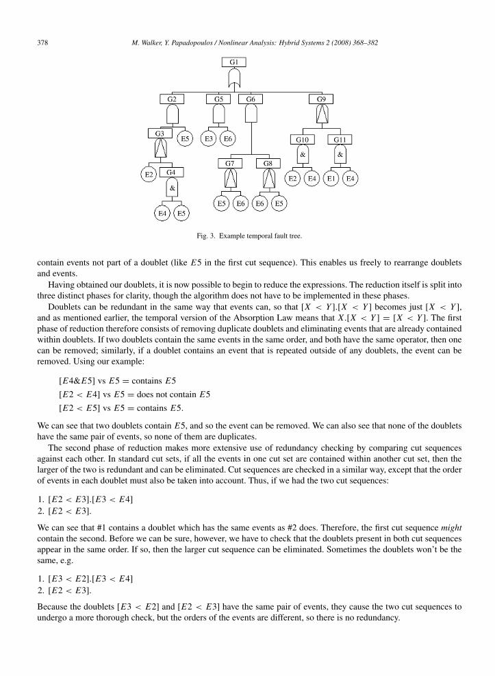
To see how doublets aid in the decomposition of a temporal fault tree, observe the small fault tree in Fig. 3. If wereduce this tree to cut sequence format, keeping the hierarchy of the tree intact using brackets, we get the following:
E5.(E2 < (E4&E5)) + E3.E6 + (E5 < E6).(E6 < E5) + (E2&E4) < (E1&E4).
Clearly, without the brackets, it would be unclear which events belong to which gates. Once we have the cutsequences, we can begin to convert them to doublets:
E5.(E2 < (E4&E5)) = E5.[E4&E5].[E2 < E4].[E2 < E5]
(E5 < E6).(E6 < E5) = [E5 < E6].[E6 < E5]
(E2&E4) < (E1&E4) = [E2&E4] < [E1&E4]
= ([E2&E4] < E1).([E2&E4] < E4).[E1&E4]
= ([E2 < E1].[E4 < E1].[E2&E4]).([E2 < E4].[E4 < E4].[E2&E4]).[E1&E4]
= [E2 < E1].[E4 < E1].[E2&E4].[E2 < E4].[E4 < E4].[E1&E4]
E3.E6 is not converted to doublets because it contains no temporal gates. Notice how that in the resulting expressions,only AND gates remain; a set of doublets connected only by AND gates is known as a doublet list, and it may also
378 M. Walker, Y. Papadopoulos / Nonlinear Analysis: Hybrid Systems 2 (2008) 368–382
Fig. 3. Example temporal fault tree.
contain events not part of a doublet (like E5 in the first cut sequence). This enables us freely to rearrange doubletsand events.
Having obtained our doublets, it is now possible to begin to reduce the expressions. The reduction itself is split intothree distinct phases for clarity, though the algorithm does not have to be implemented in these phases.
Doublets can be redundant in the same way that events can, so that [X < Y ].[X < Y ] becomes just [X < Y ],and as mentioned earlier, the temporal version of the Absorption Law means that X.[X < Y ] = [X < Y ]. The firstphase of reduction therefore consists of removing duplicate doublets and eliminating events that are already containedwithin doublets. If two doublets contain the same events in the same order, and both have the same operator, then onecan be removed; similarly, if a doublet contains an event that is repeated outside of any doublets, the event can beremoved. Using our example:
[E4&E5] vs E5 = contains E5
[E2 < E4] vs E5 = does not contain E5
[E2 < E5] vs E5 = contains E5.
We can see that two doublets contain E5, and so the event can be removed. We can also see that none of the doubletshave the same pair of events, so none of them are duplicates.
The second phase of reduction makes more extensive use of redundancy checking by comparing cut sequencesagainst each other. In standard cut sets, if all the events in one cut set are contained within another cut set, then thelarger of the two is redundant and can be eliminated. Cut sequences are checked in a similar way, except that the orderof events in each doublet must also be taken into account. Thus, if we had the two cut sequences:
1. [E2 < E3].[E3 < E4]
2. [E2 < E3].
We can see that #1 contains a doublet which has the same events as #2 does. Therefore, the first cut sequence mightcontain the second. Before we can be sure, however, we have to check that the doublets present in both cut sequencesappear in the same order. If so, then the larger cut sequence can be eliminated. Sometimes the doublets won’t be thesame, e.g.
1. [E3 < E2].[E3 < E4]
2. [E2 < E3].
Because the doublets [E3 < E2] and [E2 < E3] have the same pair of events, they cause the two cut sequences toundergo a more thorough check, but the orders of the events are different, so there is no redundancy.

M. Walker, Y. Papadopoulos / Nonlinear Analysis: Hybrid Systems 2 (2008) 368–382 379
Fig. 4. Example of a triple redundant system.
The final phase of reduction is where the temporal laws are applied and redundant doublets or impossible cutsequences (i.e. those including a contradiction) are removed. Using our example, we can see that:
E5.[E4&E5].[E2 < E4].[E2 < E5] = [E4&E5].[E2 < E4].[E2 < E5]
(E5 removed in phase 1)
[E5 < E6].[E6 < E5] = 0 (from Mutual Exclusion)
[E2 < E1].[E4 < E1].[E2&E4].[E2 < E4].[E4 < E4].[E1&E4] = 0 (from Simultaneity).
Checking for these laws is a simple matter. Mutual Exclusion means that two doublets have the same events anddifferent operators (or for PAND, different orders), and Simultaneity means that a doublet will have two events that arethe same. Cyclic redundancies are discovered in the same way, via Mutual Exclusion, because the Law of Extensionis applied during doublet generation to make sure that both the explicit and the implicit temporal relations are allproperly represented.
After the final phase of reduction, therefore, we can see that we are left with just:
[E4&E5].[E2 < E4].[E2 < E5] + E3.E6.
All that is left is to convert the remaining doublets back into normal temporal expressions. Wherever possible, temporalgates with more than two inputs are preferred over multiple temporal gates with just two inputs. In this case, theresulting minimal cut sequences are:
1. E2 < (E4&E5)
2. E3.E6.
6. Case study
Let us now apply doublet analysis to a more comprehensive example. Fig. 4 shows a system with a single sharedstandby component. The system consists of two primary components, A and B, with a single standby componentC . Component S is a selector, and requires input from two components in order to function. Initially, this input isprovided by A and B. Failure of either of these two components is detected by the respective monitors, M1 and M2.Should either of the primary components fail, the fault is detected by the monitor and the standby component C isactivated instead, allowing the selector to continue operation using the remaining primary component and the backup.Input to the system is represented by the letter “I ”. Any deviations in the input may propagate through the system andaffect the output, but for simplicity we have ignored this class of failure to focus only on component failures.
The local failure behaviour of each component is represented in HiP-HOPS with the following expressions:

380 M. Walker, Y. Papadopoulos / Nonlinear Analysis: Hybrid Systems 2 (2008) 368–382
Fig. 5. Combining local fault trees during synthesis.
Component A: O − A = AComponent B: O − B = BMonitor 1: O − M1 = M1 < O − A + M1&O − A
StartC − M1 = O − AMonitor 2: O − M2 = M2 < O − B + M2&O − B
StartC − M2 = O − BStandby C : O −C = (StartC − M1+StartC − M2).C + O − M1+ O − M2Selector S: O − S = S + O − A.O − B + O − A.O − C + O − B.O − C .
To explain, an output deviation is shown on the left of the expression, and consists of a letter representing the failureclass followed by the name of the component output, separated by a dash. Thus, O − A is an output deviation ofcomponent A with a failure class of “omission” (hence “O”). Other failure classes include C for Commission and Vfor Value, for example. On the right of the expression is a logical combination of internal failures (represented hereby the name of the component, e.g. A is an internal failure of component A, but any name could be used) and inputdeviations (represented as output deviations of source components). Thus for selector S, an omission of its output iscaused by either combinations of omissions of its inputs, or an internal failure. StartC − M1 and StartC − M2 are notfailures, but anticipated normal events generated by the monitors in response to detected omissions at the monitoredinputs. These events trigger the activation of the standby component, and are shown here separately for the sake ofclarity.
HiP-HOPS uses these expressions to propagate failures through the system and so synthesize the fault trees. First,it generates a set of fault trees for each component, one per output deviation, and then it joins these small fault treestogether to make a set of larger fault trees for the system as a whole. The tool then joins these local fault trees byworking backwards through the model from the system outputs. When it finds an input deviation, it looks for thecorresponding local fault tree for that output deviation, and glues the trees together. To illustrate part of this process,Fig. 5 shows the local fault trees for O − A and O − M1, and how they are eventually combined. Because O − Ais an input deviation that can lead to an output deviation of M1, the synthesis process will find the appropriate localfault tree (O − A, in this case) and join them together, sharing the branch if necessary. This process continues untilthere is a global fault tree for each output deviation of the system itself.
After the fault trees have been synthesized, they can then be analysed. To illustrate how doublets are used toperform temporal analysis during the analysis phase of the HiP-HOPS tool, the process will be detailed below. Asalready shown, O − M1 is combined with O − A during synthesis, and once converted into doublets (since it containstemporal gates), we get:
O − M1 = [M1 < A] + [M1&A].

M. Walker, Y. Papadopoulos / Nonlinear Analysis: Hybrid Systems 2 (2008) 368–382 381
If we then look at O − C , we can see how the expressions combine:
O − C = (StartC − M1 + StartC − M2).C + O − M1 + O − M2
= (O − A + O − B).C + [M1 < A] + [M1&A] + [M2 < B] + [M2&B]
= O − A.C + O − B.C + [M1 < A] + [M1&A] + [M2 < B] + [M2&B]
= A.C + B.C + [M1 < A] + [M1&A] + [M2 < B] + [M2&B].
Finally, we look at the failure of the system output — O − S:
O − S = S + O − A.O − B + O − A.O − C + O − B.O − C
= S + A.B + A.A.C + A.B.C + A.[M1 < A] + A.[M1&A] + A.[M2 < B] + A.[M2&B]
+ B.A.C + B.B.C + B.[M1 < A] + B.[M1&A] + B.[M2 < B] + B.[M2&B]
= S + A.B + A.C + B.C + A.B.C + B.A.C + [M1 < A] + [M1&A] + B.[M1 < A]
+ B.[M1&A] + [M2 < B] + [M2&B] + A.[M2 < B] + A.[M2&B]
= S + A.B + A.C + B.C + [M1 < A] + [M1&A] + [M2 < B] + [M2&B].
Here we can see the final results, the minimal cut sequences of the system:
1. S — Internal failure of component S2. A.B — Failure of both A and B3. A.C — Failure of both A and C4. B.C — Failure of both B and C5. M1 < A — Failure of M1 before A6. M1&A — Failure of M1 at the same time as A7. M2 < B — Failure of M2 before B8. M2&B — Failure of M2 at the same time as B.
Using doublet analysis, the fault tree has been reduced to just eight minimal cut sequences, all of which are simpleto understand and draw conclusions from. Furthermore, the results provided here are more accurate and informativethan the results that would have been provided by a purely static fault tree. To explain why, consider the expressionsused to describe the monitors once more:
O − M1 = M1 < O − A + M1&O − A.
Here we can see that an omission of output from the monitor, and therefore a failure to start the backup component C ,would be caused only if the monitor failed before or at the same time as the component it is monitoring; if the monitorM1 failed after A, C would have been started successfully. There is no way to make this distinction in a traditionalstatic fault tree, in which O − M1 would more than likely be represented by this expression:
O − M1 = M1.O − A.
It is often argued that the replacement of a PAND by an AND like this simply leads to a conservative prediction of thefailure behaviour of the system, but this claim is not necessarily true. If M1 fails after A, then the system would beable to continue to operate successfully using the backup component C . In this case, therefore, a static fault tree wouldnot be merely pessimistic, it would be factually incorrect. Similarly, one might question the validity of substitution ofa PAND with an AND in an expression like A < B.B < A.
In our example, temporal analysis has shown how what should be a redundant system with a backup can,in certain circumstances, fail without the backup component ever being activated. Looking at these results, thedesigner of the system might choose to place more emphasis on having reliable monitors and sensors to makesure the backups get to function. Using temporal gates, therefore, allows the analyst to more precisely representsuch situations, and therefore gain a more accurate and useful understanding of the failure behaviour of the system.It highlights the importance of the order in which events occur, and provides more detailed information as aresult.

382 M. Walker, Y. Papadopoulos / Nonlinear Analysis: Hybrid Systems 2 (2008) 368–382
7. Conclusions and further research
In this paper, we have described a new method of performing temporal analysis on fault trees, and described howthis process can be automated as part of a fault tree synthesis and analysis tool. By extending standard fault treeanalysis with two new temporal gates, a redefined Priority-AND gate and a Simultaneous-AND gate, it is possible torepresent the failure conditions of a system much more precisely. We can therefore obtain more accurate results fromthe analysis of systems in which time plays an important factor, improving our insight into the potential faults of thosesystems. These additions are intended to be in keeping with the simple yet flexible philosophy of FTA, and so are notlinked to any particular representation of time.
In addition, we have presented a method of analysing these new gates qualitatively and shown how it can produceuseful results for an example system. Doublet analysis can be performed either automatically or manually, but isdescribed here in the context of a semi-automatic fault tree tool, HiP-HOPS. By using doublets, it is possible tocombine the process of temporal analysis with the fault tree synthesis algorithms of HiP-HOPS, where the benefitsof a more precise analysis can be combined with the benefits of automation and potential reuse of component failuremodels. The concept of temporal analysis is particularly useful when applied to programmable systems and software,where event ordering is important for the correct operation of complex control algorithms.
The result is hopefully a powerful tool that can be used throughout all stages of the lifetime of a system, both duringdesign and during operation, to enhance the safety and reliability of the system. Because of the automated nature ofthe tool, it is possible to perform a full synthesis and analysis of a properly annotated system in a matter of minutesor even seconds, allowing the tool to be used as part of an iterative design process.
It is envisaged that the work detailed in this paper will be continued to produce a more rigorous algorithm for bothquantitative and qualitative analysis of temporal gates, with a particular eye towards how to automate it efficiently sothat it matches the performance and effectiveness of existing non-temporal FTA techniques.
Acknowledgement
This work was supported by the European Framework 6 Integrated Project SAFEDOR (IP-516278).
References
[1] Y. Papadopoulos, J.A. McDermid, R. Sasse, G. Heiner, Analysis and synthesis of the behaviour of complex systems in conditions of failure,Reliability Engineering and System Safety 71 (3) (2001) 229–247.
[2] W.E. Vesely, F.F. Goldberg, N.H. Roberts, D.F. Haasl, Fault Tree Handbook, US Nuclear Regulatory Commission, Washington DC, USA,1981.
[3] J.B. Fussel, E.F. Aber, R.G. Rahl, On quantitative analysis of PAND failure logic, IEEE Transactions on Reliability R-25/5 (1976) 324–326.[4] W. Long, Y. Sato, A Comparison between probabilistic models for quantification of Priority-AND gates, in: Proceedings of the PSAM-4,
vol. 2, 1998, pp. 1215–1220.[5] W. Long, Y. Sato, M. Horigome, Quantification of sequential failure logic for fault tree analysis, Reliability Engineering & System Safety 67
(2000) 269–274.[6] M. Cepin, B. Mavko, A dynamic fault tree, Reliability Engineering & System Safety 75 (2002) 83–91.[7] S. Amari, G. Dill, E. Howald, A new approach to solve dynamic fault trees, in: Reliability and Maintainability Symposium, 2003. Annual,
2003.[8] K. Sullivan, J. Dugan, D. Coppit, The Galileo fault tree analysis tool, in: IEEE Int’l Symp. of Fault Tolerant Computing, June 1999,
pp. 232–235.[9] R. Manian, J.B. Dugan, D. Coppit, K.J. Sullivan, Combining various solution techniques for dynamic fault tree analysis of computer systems,
in: Third IEEE International High-Assurance Systems Engineering Symposium, 13–14 November 1998, Washington DC, p. 21.[10] Y. Dutuit, A. Rauzy, A linear-time algorithm to find modules of fault trees, IEEE Transactions on Reliability R-45/3 (1996) 422–425.[11] R. Gulati, J.B. Dugan, A modular approach for analyzing static and dynamic fault trees, in: Proceedings of the Annual Reliability and
Maintainability Symposium, Philadelphia, Pennsylvania, January 1997, pp. 57–63.[12] G.K. Palshikar, Temporal fault trees, Information and Software Technology 44 (2002) 137–150.[13] P.G. Wijayarathna, M. Maekawa, Extending Fault Trees with an AND–THEN gate, in: 11th Int’l Symp. on Software Reliability Engineering,
2000.[14] R.M. Sinnamon, J.D. Andrews, New approaches to evaluating fault trees, Reliability Engineering and System Safety 58 (1997) 89–96.[15] R.B. Worrell, D.W. Stack, A SETS user manual for the fault tree analyst. NUREG CR-04651, 1978.[16] P.G. Wijayarathna, Y. Kawata, A. Santosa, K. Isogai, Representing relative temporal knowledge with the tand connective, in: Eight Ireland
Conference on Artificial Intelligence, AI-97, vol 2, 1997, pp. 80–87.[17] J.D. Andrews, To not or not to not, in: Proceedings of the 18th International System Safety Conference, September 2000, Fort Worth,
pp. 267–275.