system 65 autopilot - voneshvonesh.com/pdf_files/sys65poh.pdf · system 65 autopilot hdg vs fd/ap...
TRANSCRIPT

System 65 Autopilot
HDG
VS
FD/AP
FD
NAV
ALT
REV
YD
UP
DN
Pilot's OperatingHandbook

2nd Ed: July 31, 2002 i
SYS 65 POH
List of Effective Pages * Asterisk indicates pages changed, added, or deleted by revision.
Record of Revisions Retain this record in front of handbook. Upon receipt of a revision, insert changes and complete table below.
Revision Number Revision Date Insertion Date/Initials
1st Edition 20 Feb 2001
2nd Edition 31 Jul 2002

ii 2nd Ed: July 31, 2002
SYS 65 POH
Page Intentionally Blank

2nd Ed: July 31, 2002 iii
SYS 65 POH
Table of Contents
Section Page
1.0 Introduction..........................................................................................................1-3
2.0 Block Diagram...................................................................................................2-3
3.0 Autopilot Overview..............................................................................................3-3
3.1 System 65 Programmer/Annunciator................................................3-3
3.2 System 65 Remote Annunciator..........................................................3-4
3.3 Roll Modes of Operation.......................................................................3-4
3.3.1 Heading (HDG)........................................................................3-4
3.3.2 Navigation (NAV)......................................................................3-5
3.3.3 Reverse (REV).........................................................................3-5
3.4 Pitch Modes of Operation.....................................................................3-5
3.4.1 Vertical Speed (VS).................................................................3-5
3.4.2 Altitude (ALT)............................................................................3-6
3.4.3 Up...............................................................................................3-6
3.4.4 Down (DN)................................................................................3-6
4.0 Procedures..........................................................................................................4-3
4.1 Pre-Flight Procedures...........................................................................4-3
4.1.1 Roll Axis.....................................................................................4-3
4.1.2 Pitch/Altitude and Vertical Speed.........................................4-4
4.1.3 Autotrim......................................................................................4-5
4.2 Normal Operating Procedures...........................................................4-6
4.2.1 Roll Axis Modes.......................................................................4-6
4.2.1.1 Heading....................................................................4-6
4.2.1.2 VOR Intercept and Tracking (DG).......................4-7
4.2.1.3 VOR Approach (DG)..............................................4-8
4.2.1.4 Localizer Intercept and Tracking (DG)...............4-9
4.2.1.5 VOR/Localizer Intercept and Tracking (HSI)....4-14
4.2.1.6 Dual Mode Intercept..............................................4-15
4.2.1.7 GPS Intercept and Tracking................................4-15

iv 2nd Ed: July 31, 2002
SYS 65 POH
Table of Contents
Section Page
4.2.2 Pitch Axis Modes.....................................................................4-20
4.2.2.1 Vertical Speed.........................................................4-20
4.2.2.2 Altitude Hold............................................................4-21
4.2.2.3 Intercepting and Coupling the Glideslpoe......4-21
4.2.2.4 Manual Arm/Automatic Capture..........................4-22
4.2.2.5 Elevator Trim Indicator..........................................4-25
4.2.2.6 Optional Autotrim....................................................4-26
4.3 Flight Director Operations, Single Cue (Optional).........................4-26
4.4 Yaw Damper/Rudder Trim System (Optional)................................4-27
4.4.1 Pre-Flight Procedures............................................................4-27
4.4.2 In-Flight Procedures..............................................................4-28
5.0 Appendixes..........................................................................................................5-3
7.0 Glossary................................................................................................................6-3

2nd Ed: July 31, 2002 v
SYS 65 POH
List of Figures
Figure Page
2-1 System 65 Block Diagram...............................................................................2-3
3-1 System 65 Programmer/Annunciator............................................................3-3
3-2 System 65 Remote Annunciator......................................................................3-4
4-1 Directional Gyro..................................................................................................4-6
4-2 VOR/LOC/GPS.....................................................................................................4-8
4-3 Straight-In Localizer Approach and Tracking (DG).....................................4-10
4-4 Procedure Turn Localizer Approach and Tracking (DG)............................4-11
4-5 Back Course Straight-In Approach (DG)......................................................4-12
4-6 Back Course Procedure Turn (DG)..............................................................4-13
4-7 Straight-In Localizer Approach and Tracking (Optional HSI)....................4-16
4-8 Procedure Turn Localizer Approach and Tracking (Optional HSI)...........4-17
4-9 Back Course Straight-In Approach (Optional HSI).....................................4-18
4-10 Back Course Procedure Turn (Optional HSI).............................................4-19
4-11 Glideslope Intercept and Track......................................................................4-23
4-12 Procedure Turn for Glideslope Approach....................................................4-24
4-13 Yaw Damper Controls.....................................................................................4-27

vi 2nd Ed: July 31, 2002
SYS 65 POH
Page Intentionally Blank

2nd Ed: July 31, 2002 1-1
SYS 65 POH
SECTION 1INTRODUCTION

1-2 2nd Ed: July 31, 2002
SYS 65 POH
Page Intentionally Blank
.

2nd Ed: July 31, 2002 1-3
SYS 65 POH
1.0 Introduction
The primary purpose of the System 65 Pilot Operating Handbook (POH)is to provide pilots with step-by-step Functional Preflight and In-FlightOperating Procedures for the installed system.
NOTICE
This manual may be used in conjunction with an FAA approved autopilotAirplane Flight Manual Supplement (AFMS), Pilots Operating HandbookSupplement (POHS) or Supplemental Flight Manual (SFM). Refer to thespecific AFMS, POHS, or SFM for your aircraft specific information andemergency operating procedures.
If the autopilot is to be used during Instrument Flight Rules (IFR) operations,we recommend that you develop a thorough understanding of the autopilotsystem, its functions and characteristics in Visual MeteorologicalConditions (VMC). Accomplish this before undertaking an IFR flight.

1-4 2nd Ed: July 31, 2002
SYS 65 POH
Page Intentionally Blank

2nd Ed: July 31, 2002 2-1
SYS 65 POH
SECTION 2BLOCK DIAGRAM

2-2 2nd Ed: July 31, 2002
SYS 65 POH
Page Intentionally Blank

2nd Ed: July 31, 2002 2-3
SYS 65 POH
2.0 Block Diagram
Fig. 2-1. System 65 Block Diagram
SYS TEM 65 PR OG RA M M ER / AN NUN CIATO R
REM O TE A NNU NC IATOR
T R I MT R I MT R I MT R I M
VO R/LO C/GPS(SHO W N FOR RE FEREN CE )
AU TOPILOT D ISC ON NECT/TRIM INTE RRU PT SW ITCH
TRIM CO M MAN DSW ITCHTRIM SERVO
TRIMM ASTE R SW ITC H
SNAV
GS
HSI(OPT ION AL)
PITC H S ERV O
TUR N C OO RD INATO R
DIRE C TION A L G YR O
AB SO LU TEPRE SSUR E
TRA NSD UCER
PUSH HDG
RO LL S ERV O
YAW SE RVO(OPT ION AL)
YAW DAM PE R(OPT ION AL)
NO
P IT CH INFORMA TION
TURN COORDINATOR
2 M IN
FL IG HT D IREC TOR(OPT ION AL)
RO LLCO M PUTE R
PITC HCO M PUTE R
SELECTOR/ALERTER(OPTIONAL)
A/P DISC
HDG
VS
FD/AP
FD
NAV
ALT
REV
YD
UP
DN
SEL ALRALR DH VS BARO
ENT

2-4 2nd Ed: July 31, 2002
SYS 65 POH
Page Intentionally Blank

2nd Ed: July 31, 2002 3-1
SYS 65 POH
SECTION 3AUTOPILOT OVERVIEW

3-2 2nd Ed: July 31, 2002
SYS 65 POH
Page Intentionally Blank

2nd Ed: July 31, 2002 3-3
SYS 65 POH
3.0 Autopilot Overview
3.1 System 65 Programmer/Annunciator
Fig. 3-1. System 65 Programmer/Annunciator
The System 65 Programmer/Annunciator is a rate based autopilot thatcontrols the roll and pitch axis of the aircraft. The autopilot's mainfunction is to convert pilot commands to logic signals for both the rolland pitch computers. As the pilot enters the desired mode by pressingthe mode selector switch, the computer acknowledges the selectionby illuminating that annunciator.
The Roll Computer receives signal inputs from the turn coordinator,Directional Gyro (DG) or optional Horizontal Situation Indicator (HSI),Very High Frequency Omnidirectional Radio Range (VOR) / Localizer(LOC), Long Range Navigation (LORAN) and the Global PositioningSystem (GPS) navigation receivers. It then computes roll servocommands for stabilization, turns, radio intercepts, and tracking.
The Pitch Computer receives signal inputs from the altitude pressuretransducer, internal accelerometer, glideslope deviation indicator, andoff warning flag contained in the glideslope receiver. The pitch systemprovides vertical speed control and altitude hold, as well as automatic/manual glideslope capture.
Vertical speed reference is provided by the barometric pressuretransducer, while automatic and manual pitch trim sensing is providedby the pitch servo. Drive for the elevator trim servo is provided by thepitch computer. All modes use the transducer signal for a VS or ALTreference.
HDG
VS
FD/AP
FD
NAV
ALT
REV
YD
UP
DN

3-4 2nd Ed: July 31, 2002
SYS 65 POH
3.2 System 65 Remote Annunciator
The System 65 Remote Annunciator is standard equipment (notoptional) with the System 65 Autopilot. The remote annunciator displaysall the modes selected on the autopilot programmer, as well asconditions of those modes. Examples of these conditions include:NAV gain, NAV failure, GS disable (DSBL) and out of trim conditions.
In addition, both SEL and Glideslope (GS) are annunciated only on theremote annunciator. The "SEL" annunciator indicates that the optionalAltitude Selector / Alerter is in use. The GS annunciator indicates thatthe autopilot is in glide-slope mode and the pitch annunciator in theautopilot programmer will be blank.
NOTE: It is very important that the pilot monitor the remoteannunciator as well as the autopilot programmerduring all autopilot operations and especially duringapproach operations.
3.3 Roll Modes of Operation
3.3.1 Heading (HDG)
The HDG mode provides heading preselect and turns through the useof the heading bug on the Directional Gyro (DG) or optional HorizontalSituation Indicator (HSI).
Fig. 3-2. System 65 Remote Annunciator
HDG
VS
FD/AP
FD
NAV
ALT
REV
YD
UP
DN

2nd Ed: July 31, 2002 3-5
SYS 65 POH
3.3.2 Navigation (NAV)
The NAV mode provides roll commands for automatic intercept andtracking of selected VOR/LOC/LORAN/GPS navigational signals.
3.3.3 Reverse (REV)
REV mode provides roll commands for automatic intercept and trackingof the back course localizer inbound or the front course localizeroutbound.
3.4 Pitch Modes of Operation
NOTE: Before engaging a pitch mode of operation, a rollmode must first be engaged.
3.4.1 Vertical Speed (VS)
The VS mode provides pitch synchronization of the autopilot to theaircraft vertical speed. To activate, press the VS mode switch. Thisactivates the UP/DN (Down) pitch modifier switches for pilot commandedchanges of vertical speed, up to a maximum of +/- 1600 feet-per-minute(rate of climb / descent).
HDG
VS
FD/AP
FD
NAV
ALT
REV
YD
UP
DN
HDG
VS
FD/AP
FD
NAV
ALT
REV
YD
UP
DN

3-6 2nd Ed: July 31, 2002
SYS 65 POH
3.4.2 Altitude (ALT)
The ALT mode engages the altitude hold mode, capturing the altitudeattained at the time of activation.
3.4.3 UP
When the VS mode is activated, the UP modifier switch will increase therate-of-climb or decrease the rate-of-descent at 160 FPM for eachsecond of continuous switch depression.
3.4.4 Down (DN)
When the VS mode is activated, the DN switch will increase the rate-of-descent or decrease the rate-of-climb 160 FPM for each second ofcontinuous switch depression.
HDG
VS
FD/AP
FD
NAV
ALT
REV
YD
UP
DN
HDG
VS
FD/AP
FD
NAV
ALT
REV
YD
UP
DN
HDG
VS
FD/AP
FD
NAV
ALT
REV
YD
UP
DN

2nd Ed: July 31, 2002 3-7
SYS 65 POH
When the altitude hold mode is engaged, the UP and DN switches maybe used to adjust the altitude. The UP and DN switches produce a 20 footchange in altitude for each second of depression, up to a maximum of200 feet. Altitude changes of more than 200 feet require reactivation ofthe VS mode.
NOTE: For aircraft without auto trim, or where auto trim isdisabled or turned off, the UP/DN annunciators are usedto annunciate out of trim conditions when either the VSor ALT modes are engaged. If up trim is required, the UPannunciator will illuminate. If down trim is needed, theDN annunciator will illuminate. In both cases, the TRIMannunciation will also illuminate. The pilot shouldmanually trim the aircraft in the direction indicated, untilthe light extinguishes. The aircraft will then be trimmedfor existing flight conditions.
NOTE: There are four ways to disengage the autopilot (A/P):
1. Press the A/P disconnect/trim interrupt switch (normallymounted on the control wheel).
2. If pitch axis is engaged, operate the trim switch either way.(This will not disconnect the A/P if Autotrim is disabled ornot installed).
3. Push the FD / AP switch. The ON annunciator will extinguish.
4. Locate and pull the autopilot circuit breaker.
HDG
VS
FD/AP
FD
NAV
ALT
REV
YD
UP
DN
HDG
VS
FD/AP
FD
NAV
ALT
REV
YD
UP
DN

3-8 2nd Ed: July 31, 2002
SYS 65 POH
Page Intentionally Blank

2nd Ed: July 31, 2002 4-1
SYS 65 POH
SECTION 4PROCEDURES

4-2 2nd Ed: July 31, 2002
SYS 65 POH
Page Intentionally Blank

2nd Ed: July 31, 2002 4-3
SYS 65 POH
4.0 Procedures
4.1 Pre-Flight Procedures
NOTE: To perform the system function check, adequate DCvoltage must be supplied to the system, either 12 or 24VDC, depending on the aircraft.
4.1.1 Roll Axis
The following is a step by step procedure for preflighting the Roll Axis:
1. Push the System 65 Flight Director (FD) /Autopilot (AP) Switch to turnon the autopilot (This is the Autopilot Master Switch). Note that "ON"is displayed in the autopilot programmer upper left corner.
2. Verify within three minutes Ready (RDY) alone becomes annunciatedon the A/P Remote Annunciator.
3. Verify that the low voltage flag on the Turn Coordinator is out of view.
4. Rotate the heading knob on the Directional Gyro (DG) to position theheading bug under the lubber line.
5. Engage the HDG mode, and observe the HDG annunciation. Movethe heading bug left and right. The control wheel should move inthe direction of bug travel. Return the bug to center.
6. Grasp the control wheel and manually turn it left and right tooverpower the roll servo. There should be a noticeable increase incontrol wheel friction, no excessive looseness, no ratcheting or noise.
7. Turn on the NAV radio and tune a valid VOR signal. Then engage theNAV mode, observing the NAV annunciation. Move the VOR/Omnibearing Selector (OBS) so that the needle swings left and right. Thecontrol wheel should move in the direction of needle travel (workswith Standard DG not HSI). NAV annunciation should flash whenCourse Deviation Indicator (CDI) deflection is over 50%.
8. Select REV mode, and observe the REV annunciation. Again, rotatethe VOR/OBS knob. The control wheel should move opposite todirection of needle travel (Only works with Standard DG not HSI).NAV annunciation should flash when CDI deflection is over 50%.
9. Channel a nonvalid VOR signal. NAV annunciation should flash,and FAIL annunciation should illuminate (if the radio has a NAV flagoutput).

4-4 2nd Ed: July 31, 2002
SYS 65 POH
10. Disconnect by pressing and releasing the control wheel mountedA/P disconnect switch. Move the control wheel to ensure freedomof controls, and check to see that the RDY annunciator is flashingfor approximately 5 seconds to indicate autopilot disconnect.
4.1.2 Pitch/Altitude and Vertical Speed
The following is a step by step procedure for preflighting the Pitch/Altitude and Vertical Speed Systems:
1. Be sure the FD/AP switch indicates ON, and that a roll axis modehas been selected (for example: HDG mode).
2. Move the control wheel to level flight position and engage the VSmode. Press the UP modifier switch and hold. The control wheelshould move aft, slowly. Press the DN switch and hold. The controlwheel should move slowly forward.
NOTE: On some aircraft the autopilot may not be able to liftthe elevators without pilot assistance during groundoperation.
3. Place Trim Master Switch to OFF (if autotrim is installed).
4. Overpower the pitch function by pulling the control wheel slowly aft.The TRIM and DN annunciator should illuminate after 3 seconds.Slowly push the control wheel forward. After 3 seconds, the TRIMand UP annunciator should illuminate. During overpower, thereshould be no excessive play in the controls or ratcheting noise.
5. Manual Pitch Limiter Test:
A. Disconnect the autopilot. Push the FD/AP switch to extinguish"ON" in the programmer.
B. Move the aircraft control wheel until the elevator is in the neutralposition and hold there.
C. Press and hold the UP modifier switch while maintaining agrasp on the control wheel. Audible warning should sound.
D. Verify the pitch servo momentarily engages and then disengages.Release the UP switch.
E. Press and hold the DN switch while maintaining a grasp on thecontrol wheel. Audible warning should sound.
F. Verify the pitch servo momentarily engages and then disengages.Release the DN switch.

2nd Ed: July 31, 2002 4-5
SYS 65 POH
6. Verify that the autopilot is disconnected and move controls to ensurefreedom of movement. Trim aircraft for takeoff.
CAUTION
If the pitch servo does not disengage when either the UP or DNmodifier switch is pressed, the limit accelerometer may havefailed. Do not use the autopilot pitch section until the problemis corrected. This check should be performed once per flightday. (Check Federal Aviation Administration (FAA) approvedAFMS).
NOTE: If optional autotrim is not installed, this is the end ofthe preflight test.
7. If the autopilot is equipped with optional autotrim, proceed with thefollowing steps:
A. Trim Master Switch to ON.
B. Operate manual trim switch (both segments) nose DN, autopilotTRIM annunciator flashes, trim moves nose down (check manualtrim wheel).
C. Operate trim switch (both segments) UP, autopilot TRIMannunciator flashes, trim moves nose up (check manual trimwheel). Grasp aircraft trim control and overpower electric trim.
D. Operate each segment of the trim switch separately. Trim shouldnot operate unless both halves of the trim switch are operatedsimultaneously in the same direction.
E. With trim operating, press trim interrupt switch. Trim motion shouldcease while interrupt switch is activated. Trim motion shouldresume when interrupt switch is released.
4.1.3 Autotrim
1. Trim Master Switch ON, engage autopilot HDG and VS modes.
2. Grasp control wheel, slowly push forward. After approximately 3econds, trim should run nose up.
3. Slowly pull control wheel aft. After approximately 3 seconds, trimshould move nose down.
4. Move manual trim switch up and down. Autopilot disengages, trimshould operate in commanded direction (trim switch will disengageautopilot only when pitch is engaged).
5. Reengage HDG and VS modes and press TRIM INTR/AP DISCswitch. Autopilot should disengage.

4-6 2nd Ed: July 31, 2002
SYS 65 POH
6. Trim aircraft for takeoff and check controls for freedom of movement.Be sure the autopilot and trim are disengaged.
CAUTION
If either the manual electric trim or autotrim fails during anyportion of the preflight, turn trim master switch OFF. Do notuse the electric trim until the fault is corrected. With trimmaster switch OFF, the autopilot trim indicators and audiowarning are reactivated. If the electric trim fails, or has an in-flight power failure, the system automatically reverts toindicator lights and audio warning. Should this occur, turntrim master switch OFF, and revert to aircraft manual trimuntil the fault is corrected.
4.2 NORMAL OPERATING PROCEDURES
NOTE: RDY must be illuminated on the remote annunciator andON must be displayed on the autopilot programmer, inorder to activate any mode of the System 65 autopilot.
4.2.1 Roll Axis Modes
4.2.1.1 Heading
1. Trim the aircraft for existing flight conditions.
2. Set the heading bug on the DG or optional HSI to the desired HDGand press the HDG switch.
NOTE: The HDG annunciator will illuminate. A new HDG can beselected by repositioning the heading bug. Whenoperating in the HDG mode, the system is not coupled toany ground navigation device. It flies a specific heading,only. It will be necessary to monitor navigation instrumentsfor course deviation due to wind drift, and to establishwind correction angles.
Fig. 4-1. Directional Gyro
P US H H DG

2nd Ed: July 31, 2002 4-7
SYS 65 POH
4.2.1.2 VOR Intercept and Tracking (DG)
1. To intercept and track a VOR signal, tune the navigation radioreceiver to the proper frequency.
2. Select the desired VOR radial on the NAV indicator.
3. Move the heading bug in the direction of desired travel, to match thecourse of selected radial.
4. Engage the NAV mode.
NOTE: If the VOR needle is at full-scale deviation, the autopilotwill establish a 45º intercept angle to the desired course.As the aircraft approaches the selected radial, theautopilot senses the closure rate, and gradually,smoothly, shallows the intercept angle. The point thatthis turn begins is variable, depending on the aircraftposition and closure rate to the radial. However, the turnwill always begin between 100% (full-scale) needledeflection and 20% of full-scale. During the interceptsequence, the system operates in maximum gain andsensitivity to needle position and can command 90% ofa standard rate turn.
When the selected course is intercepted and the needleis within 15% of centered, the CAP annunciatorilluminates indicating course capture and initiation of thetracking gain sequence. This high sensitivity level ismaintained for approximately 15 seconds while windcorrection angle is established. Turn rate capability isthen reduced to 45% standard turn rate (Capture/SoftGain) identified by both the CAP and SOFT annunciation's.
Approximately 60 seconds later, the maximum turn rateis reduced to 15% of standard rate (Soft Gain), and thelowest level of sensitivity is achieved, identified by theNAV and SOFT annunciation's. CAP annunciationextinguishes. This condition provides low activity levelsduring station passage when VOR signals are erratic.
HDG
VS
FD/AP
FD
NAV
ALT
REV
YD
UP
DN

4-8 2nd Ed: July 31, 2002
SYS 65 POH
The system includes a course deviation monitor. If the aircraft strays offcourse or LOC centerline by 50% needle deflection, the NAV annunciatorflashes as a warning. It should flash at station passage because ofshort-term needle excursion beyond 50%. It also flashes when the NAVflag is in view. When that occurs, the FAIL annunciation will illuminate.
NOTE: When operating in the NAV/ SOFT mode, and needledeflection of 50% or more is experienced for 1½ minutes,the gain program will switch to NAV/CAP/SOFT, increasingsensitivity and authority to re-establish the aircraft oncourse. When a course change of 10º or more is requiredat an enroute waypoint, select the new course, and resetthe NAV mode to reinstate the capture sequence. Set theDG heading bug to the new course.
4.2.1.3 VOR Approach (DG)
During a VOR approach, it is recommended that the NAV mode switchbe depressed just after TO/FROM reversal after the needle has stabilizedat the Final Approach Fix (FAF) inbound .
This returns the system to capture dynamics and reinstates the highsensitivity gain scheduling.
SNAV
GS
Fig. 4-2. VOR/LOC/GPS

2nd Ed: July 31, 2002 4-9
SYS 65 POH
4.2.1.4 Localizer Intercept and Tracking (DG)
When a localizer frequency is channeled, and NAV mode is selected, thesystem will automatically execute high sensitivity gain for the approachand automatically activates the APR mode. NAV/APR illuminates on theremote annunciator.
Set the heading bug to the inbound localizer course, and engage theNAV mode to intercept and track the localizer front course inbound orback course outbound.
PUSH H DG
HDG
VS
FD/AP
FD
NAV
ALT
REV
YD
UP
DN

4-10 2nd E
d: July 31, 2002
SY
S 65 P
OH
Straight-in Localizer Approach and Tracking (DG)
1. a. Tune navigation radio to localizer frequency.
b. Set HDG bug to published inbound course. c. Press NAV mode switch. Autopilot will intercept, capture and track the localizer course.
2. If a missed approach is declared at the middle marker:
a. Disconnect the autopilot and stabilize the aircraft for the missed approach climb. b. Set the HDG bug to the published missed approach heading. c. Press the HDG mode switch. d. Press the VS mode switch if desired.
Fig. 4-3

2nd Ed: July 31, 2002
4-11
SY
S 65 P
OH
Procedure Turn Localizer Approach and Tracking (DG)
1 .
2 6 5
N
0 8 5
2 .
3 .
4 .
3 1 0
3 1 0
1 3 0
1. a. Tune navigation radio to LOC frequency.
b. Set heading bug to published outbound LOC heading.
c. Push REV mode switch. 2. a. Set heading bug to outbound procedure turn heading.
b. Press HDG mode switch. 3. In 90 increments, set heading bug to inbound procedure turn heading. 4. a. Set heading bug to inbound LOC heading.
b. Press NAV mode switch. Autopilot will intercept, track, and capture localizer course inbound to the airport.
Fig. 4-4

4-12 2nd E
d: July 31, 2002
SY
S 65 P
OH
Back Course Straight-In Approach (DG)
1. a. Tune navigation radio to LOC frequency.
b. Set heading bug to the back course inbound final approach heading.
c. Press REV mode switch. Autopilot will intercept and track the back course to the airport.
Fig. 4-5
265 085Back Course
310
N

2nd Ed: July 31, 2002
4-13
SY
S 65 P
OH
Back Course Procedure Turn (DG)
1. a. Tune navigation receiver to LOC frequency.
b. Set heading bug to published inbound front course heading.
c. Press NAV mode switch. 2. a. Set heading bug to outbound procedure turn heading.
b. Press HDG mode switch. 3. In 90 increments, set heading bug to inbound procedure turn heading. 4. a. Set heading bug to published final approach course heading.
b. Press REV mode switch. Autopilot will complete intercept, capture and tracking of localizer back course, inbound.
Fig. 4-6
2 6 5
N
0 8 5
3 1 0
1 3 0
1 .
2
B a c k C o u rs e

4-14 2nd Ed: July 31, 2002
SYS 65 POH
4.2.1.5 VOR/Localizer Intercept and Track (HSI Option)
If your aircraft is equipped with an optional HSI, the autopilot will receiveboth VOR left/right information and course information. With an HSI, theheading bug is not used during radio tracking. To make a VOR orLocalizer Approach, tune the navigation receiver to the required frequency.Set the desired VOR radial or Localizer course with the course selector.Press and release the NAV mode switch.
NOTE: Localizer approaches with an HSI require that the inboundfront course be set on the course selector for either frontcourse or back course operations. To track inbound onthe front course, activate the NAV mode. NAV mode alsois used for tracking outbound on the back course.
To fly the back course, activate the REV mode. It is used to track inboundon the back course, and outbound on the front course. The courseselector must be set to the inbound front course.
HDG
VS
FD/AP
FD
NAV
ALT
REV
YD
UP
DN
HDG
VS
FD/AP
FD
NAV
ALT
REV
YD
UP
DN

2nd Ed: July 31, 2002 4-15
SYS 65 POH
4.2.1.6 Dual Mode Intercept
NOTE: During operations with an HSI, simultaneous activationof both the HDG and NAV modes will provide selectedangle intercepts. Selected angle intercepts may be usedduring VOR, localizer front course and back course (REV)operations. In flying a radial or localizer intercept, theautopilot will follow the heading bug until the aircraftreaches the proper on course turn point. It will then switchfrom HDG to NAV mode automatically.
Localizer intercept angles greater than 45º usually result in some courseovershoot, depending on the distance from the station and speed ofthe aircraft. Therefore, angles greater than 45º are not recommended.
4.2.1.7 GPS Intercept and Tracking
The System 65 Autopilot can also be used to intercept and track validGPS signals for cross country or approach operations using theautopilot NAV mode as follows:
1. Program the desired waypoint or initial approach fix into the GPSnavigator and verify a valid signal is being received.
2. If using a DG, set the heading bug on the desired track to the waypoint,then select the NAV mode. The autopilot will intercept and track thebearing to the waypoint.
3. If using an HSI, set the course arrow (instead of the heading bug),to the desired track to the waypoint before selecting the NAV mode.
4. If conducting a GPS approach, be sure to note the suggested bearingto each new waypoint as each segment of the approach iscompleted and set the heading bug or course arrow as appropriate.If making course changes of more than 10º when crossing awaypoint, press the NAV switch again to reinstate the capturesequence.
5. For procedure turns, the pilot must select the HDG mode and fly theaircraft through the turn then select the NAV mode again.
HDG
VS
FD/AP
FD
NAV
ALT
REV
YD
UP
DN

4-16 2nd E
d: July 31, 2002
SY
S 65 P
OH
S tra ight-in Localizer Approach and Tracking (O ptional H S I)
1 . a . Tune naviga tion rad io to LO C frequency. b . S e t course po in te r to pub lished inbound L O C cou rse head ing .
c . P ress N A V m ode sw itch . A utop ilo t w ill in te rcept, cap ture , and track the loca lize r. 2 . a . O nce N A V m ode is es tab lished , head ing bug can be se t to pub lished m issed
b . A t the m idd le m arker, if a m issed approach is dec la red , d isconnec t the au top ilo t and s tab ilize th
a irc ra ft fo r the m issed app roach c lim b be fo re engag ing H D G m ode . N O TE : To es tab lish a p ilo t se lec tab le ang le o f in te rcep t (dua l m ode in te rcept), se t the course
po in te r to the pub lished inbound fron t cou rse head ing , and the head ing bug to the des ired head ing to es tab lish the se lec ted ang le in te rcept o r to the R adar V ec tor H D G . P ress the H D G and N A V m ode sw itches s im u ltaneous ly. U pon cap ture o f cou rse , the au top ilo t au tom atica lly cance ls H D G m ode and tracks the fina l approach course . H ead ing bug can be se t to m issed app roach head ing a fte r cou rse cap tu re .
F ig . 4 -7

2nd Ed: July 31, 2002
4-17
SY
S 65 P
OH
Procedure Turn Localizer Approach and Tracking (Optional HSI)
1.
265
N
085
2.
3.
4.
310
310
130
1. a. Tune navigation radio to LOC frequency.
b. Set published inbound LOC course heading with course pointer.
c. Push REV mode switch. 2. a. Set heading bug to published outbound procedure turn heading.
b. Press HDG mode switch. 3. a. In 90 increments, set heading bug to inbound procedure turn heading.
b. When established on inbound procedure turn heading, press NAV mode switch. Autopilot will intercept, track, and capture the localizer.
4. Once established in NAV/APR mode, the heading bug can be set to the published missed approach heading.
Fig. 4-8
4-18 2nd E
d: July 31, 2002
SY
S 65 P
OH
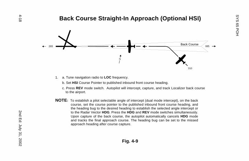
Back Course Straight-In Approach (Optional HSI)
1. a. Tune navigation radio to LOC frequency.
b. Set HSI Course Pointer to published inbound front course heading.
c. Press REV mode switch. Autopilot will intercept, capture, and track Localizer back course to the airport.
NOTE: To establish a pilot selectable angle of intercept (dual mode intercept), on the back
course, set the course pointer to the published inbound front course heading, and the heading bug to the desired heading to establish the selected angle intercept or to the Radar Vector HDG. Press the HDG and REV mode switches simultaneously. Upon capture of the back course, the autopilot automatically cancels HDG mode and tracks the final approach course. The heading bug can be set to the missed approach heading after course capture.
Fig. 4-9
265 085Back Course
310
N

2nd Ed: July 31, 2002
4-19
SY
S 65 P
OH
Back Course Procedure Turn (Optional HSI)
REVerse mode is used to track the front course outbound or the back course inbound to the airport. The HSI Course Pointer MUST be set to the front course inbound heading.
1. a. Tune the navigation receiver to the LOC frequency.
b. Set the course pointer to the published inbound LOC front course heading.
c. Press the NAV mode switch. The autopilot will track the back course outbound. 2. a. Set the heading bug to the published outbound procedure turn heading.
b. Press the HDG mode switch. 3. a. In 90 increments, set the heading bug to the inbound procedure turn heading. 4.
b. Position the aircraft on the localizer Back Course with the HDG bug.
c. Press REV mode switch. The autopilot will track the back course inbound to the airport.
Fig. 4-10
265
N
085
310
130
1.
2.
3.
Back Course

4-20 2nd Ed: July 31, 2002
SYS 65 POH
4.2.2 Pitch Axis Modes
NOTE: A Roll Mode must be selected before selecting a PitchMode.
4.2.2.1 Vertical Speed (VS)
When establishing an automatic climb out to a desired altitude (withoutoptional ALT Selector Alerter), press and release the VS mode switch toengage the vertical speed mode. The autopilot automaticallysynchronizes to the established rate-of-climb or descent.
If the established rate-of-climb exceeds 1600 FPM, at VS engagement,the autopilot will seek to maintain 1600 FPM. Should a specific rate-of-climb/descent be required, press the appropriate UP/DN modifierswitch.
For each second of depression (UP or DN), there is a 160 FPM changeof vertical speed. For example, to establish a 500 FPM rate-of-climb,press and hold the UP modifier switch for approximately 3 seconds totransition from level flight to a 500 FPM climb. To descend atapproximately 500 FPM, press the DN switch for approximately 3seconds.
NOTE: If the VS mode annunciator flashes, it indicates anexcessive error between the actual VS compared to theselected VS. The pilot should adjust the aircraft power orcorrect the VS that has been selected.
CAUTION
Vertical speed change is time related: 160 FPM for eachsecond of switch depression. Autopilot response to acommanded VS change is precise. DO NOT continue todepress modifier switches beyond the time required toprogram the desired vertical speed change. In other words,until the attitude change "looks right". The autopilot willchange attitude very slowly in the direction of the command.
Operation of the optional altitude / vertical speed selector is containedin a separate manual.
HDG
VS
FD/AP
FD
NAV
ALT
REV
YD
UP
DN

2nd Ed: July 31, 2002 4-21
SYS 65 POH
4.2.2.2 Altitude Hold (ALT)
Upon reaching the desired or assigned altitude, press and release theALT switch. The altitude hold mode will engage at the altitude reachedat the time of engagement. There is typically no need to "lead" thedesired altitude. If there is a difference between the altitude engagementpoint and the altimeter, use the appropriate UP/DN modifier switch tomake the necessary altitude correction.
NOTE: While in the altitude mode, 1 second of modifier switchdepression will change the altitude approximately 20 ft.,up to a maximum of 200 feet.
NOTE: If more than 200 feet of altitude correction is necessary,re-engage the VS mode, fly to the desired altitude, andre-engage the ALT mode.
4.2.2.3 Intercepting and Coupling the Glideslope
To arm the automatic glide-slope (GS) capture function, the followingconditions must be met:
1. NAV receiver must be tuned to the appropriate frequency.
2. The glide-slope signal must be valid; no flag.
3. The autopilot must be in NAV / APR / ALT modes.
4. The aircraft must be 60% or more below the GS centerline duringthe approach to the intercept point, and within 50% needle deviationof the localizer centerline at the point of intercept, usually the outermarker.
HDG
VS
FD/AP
FD
NAV
ALT
REV
YD
UP
DN

4-22 2nd Ed: July 31, 2002
SYS 65 POH
NOTE: GS arming will occur when the above conditions haveexisted for 10 seconds. Illumination of the GS annunciatorwill occur, indicating arming has been accomplished.The ALT annunciator remains on. GS capture is indicatedby extinguishing of the ALT annunciation at GS intercept.This should occur at 5% below the GS center-line.
4.2.2.4 Manual Arm / Automatic Capture
If approach vectoring locates the aircraft above or too near the GS center-line at the intercept point, usually the outer marker, it becomes necessaryto execute a manual arming of the GS. This is done by:
1. Pressing the ALT switch once if operating in the altitude hold mode.
2. Pressing the ALT switch twice if operating in the VS mode. Oncecapture is achieved, the GS annunciation will illuminate, and theALT annunciation will extinguish.
NOTE: If it becomes necessary to establish a holding pattern atthe outer marker, automatic glide-slope arming can bedisabled by pressing the NAV switch a second time whilein the NAV / APR mode. The GS annunciator will flash,and the Disable (DSBL) annunciator will illuminate, toindicate that the GS mode is disabled. To re-establishGS arming, press the NAV mode switch again. The DSBLcondition annunciator will extinguish, the GS annunciatorwill cease to flash.
HDG
VS
FD/AP
FD
NAV
ALT
REV
YD
UP
DN

2nd Ed: July 31, 2002
4-23
SY
S 65 P
OH
Glideslope Intercept and Track
Flying the Glideslope NOTE: When making an ILS approach, be sure to follow the published procedure for the approach you have
been cleared to make. (See text for Localizer Intercept and Tracking.) 1. Approach the glide-slope intercept point with the aircraft stabilized in the Altitude Hold (ALT) mode.
2. If the aircraft requires approach flaps, lower the flaps to the proper position. (refer to FAA/AFM supplement for flap use limitations.)
3. At glide-slope intercept, lower the landing gear (if applicable) and adjust power for the desired descent speed and published rate of descent. For best tracking results, make small power adjustments to maintain the desired rate of descent and airspeed.
4. At the decision height, or the autopilot’s minimum operating altitude, whichever is higher, disengage the autopilot to execute a manual landing, or a go-around manuver. If a missed approach is declared, the autopilot can be re-engaged after a stabilized climb has been established.
Fig. 4-11

4-24 2nd E
d: July 31, 2002
SY
S 65 P
OH
Procedure Turn for Glideslope Approach
1. a. Tune navigation radio to ILS frequency.
b. Follow the procedure(s) for LOC Approach Intercept and Tracking in this manual. 2. a. If a procedure turn is required, enter the procedure turn at the published procedure turn altitude or descend to it.
b. At the procedure turn altitude, press the VS mode switch.
c. Inbound to the Final Approach Fix (FAF) engage ALT mode, if not already in altitude hold.]
d. When the NAV mode switch is pressed, and if the aircraft is below the glide-slope, the APR and GS annunciations will illuminate.
3. a. Upon capture of LOC course, NAV, APR, ALT and GS will illuminate if all conditions for glide-slope operation are
met (see text, ref. Glide-slope Operation). This signifies automatic arming of the glide-slope function.
b. Upon glide-slope capture, the ALT annunciation will extinguish, signifying GS capture. NOTE: If the final approach flown locates the aircraft above the glide-slope prior to reaching the outer marker,
follow the procedure outlined in the text for manual arming of the glide-slope.
Fig. 4-12

2nd Ed: July 31, 2002 4-25
SYS 65 POH
NOTE: To fly a holding pattern, if inbound to the outer markerwhile in NAV mode, press the NAV switch a second timeto disable the GS arming. When the outer marker isreached, press and release the HDG switch, and rotatethe heading bug in the direction of the turn. It is best toselect the reciprocal course in increments of 90º, ratherthan the full 180º. When the outbound leg is completed,rotate the HDG bug in the direction of the turn, in 90ºincrements, to re-establish the inbound course, andpress and release the NAV switch twice. On the inboundleg, when ready to complete the approach, rearm the GSfunction by pressing and releasing the NAV switch onceagain. Rearming will occur when all other requiredfunctions have been met.
4.2.2.5 Elevator Trim Indicator
The autopilot pitch servo contains a sensor for detection of elevator out-of-trim loads. Without optional Autotrim, when such forces exceed apreset level, the TRIM annunciator will illuminate, and either the UP orDN annunciator will light up, indicating the direction of required trim.Annunciation will be steady for about 5 seconds, then will flash untilproper trim conditions have been met.
NOTE: If the TRIM annunciation is illuminated and the autopilotis disengaged, there will be a residual out-of-trim force atthe control wheel. Be alert for this condition if the autopilotis disengaged while the TRIM lights are on.
HDG
VS
FD/AP
FD
NAV
ALT
REV
YD
UP
DN

4-26 2nd Ed: July 31, 2002
SYS 65 POH
4.2.2.6 Optional Autotrim
If the autopilot is equipped with optional Autotrim, the aircraft elevatortrim will be maintained automatically when the Trim Master Switch is ONand a pitch mode is activated.
When the Trim Master Switch is ON, the trim annunciators are disabled.If the switch is OFF, or a power failure occurs, the annunciatorsautomatically become functional.
The trim system is designed to accept any type of single failure,mechanical or electrical, without uncontrolled operation resulting.Toensure that no hidden failures have occurred, conduct a trim preflightcheck prior to every flight. (See Airplane Flight Manual / Pilot OperatingHandbook.)
4.3 Flight Director Operations, Single Cue (Optional)
This system, which integrates both the roll and pitch axis, offerssynchronized display of the flight profile. It is automatically activated whenthe autopilot pitch axis is engaged. A Flight Director (FD) provides a visualindication of how accurately the pilot or autopilot is tracking the commandsof the active mode of operation.
To activate only the Flight Director, press the FD switch in the lower leftcorner of the autopilot programmer (Note that "ON" is annunciated in thelower left corner of the programmer display panel). The Flight Director isnow ready to be programmed by selecting a roll mode and then a pitchmode. The steering bar will not come into view until a pitch mode isselected. A remote parallax adjustment is provided to change the heightof the horizontal display to compensate for different seat heights. FDmode disables the autopilot servos, allowing the pilot to control the aircraftto flight director commands. To return to autopilot flight simply push theFD / AP switch.
For proper flight technique, the system presentation requires the pilot toroll and pitch the aircraft toward the display until the delta shapedreference is tucked into the steering command bars, indicating thatcommands have been satisfied. For example, if the display is up andleft, the pilot would be required to establish a left turn, pitch up attitude.
As bank angle and vertical speed approach the required amounts, bankangle and pitch up attitude are shallowed. When the delta reference andthe steering bars are matched, the commands have been met. Thereafter,it is necessary to maneuver the aircraft to keep the display elementsmatched in order to accurately fly the selected modes.
Accurate flight-director operation requires alertness by the pilot andmonitoring the movement of the display. Keeping it matched is quitesimple. However, control inputs must be timely and smooth foraccurate flight director responses following the desired command.

2nd Ed: July 31, 2002 4-27
SYS 65 POH
4.4 Yaw Damper/Rudder Trim System (Optional)
The S-TEC accelerometer controlled Yaw Damper / Rudder Trim Systemsubstantially improves autopilot performance, as it senses both yawand slip in a single sensor. It also contains a trim potentiometer thatallows centering of the turn and slip ball. It replaces the commonlyused rate gyro with a sensitive accelerometer.
The S-TEC system offers two modes of operation:
1. When the optional Yaw Damper (YD) is used with the System 65Autopilot, activation of any roll axis mode (HDG, NAV, etc.) will alsoengage the Yaw Damper. The Yaw Damper can be disengagedanytime by pressing and releasing the YD switch on the autopilot.
2. If Yaw Damper use without the autopilot is desired, simply pressthe YD switch on the autopilot.
Fig. 4-13 Yaw Damper Controls
4.4.1 Pre-Flight Procedures
1. Press the FD/AP switch on the System 65 Programmer. Next pressthe HDG switch. Note that the Yaw Damper has engaged and causesincreased rudder pedal force. The YD annunciator is displayed onboth the autopilot and the remote annunciator.
2. Turn the Trim Control counter-clockwise and note that the left rudderpedal slowly moves forward. Turn the Yaw Trim Control clockwiseand note that the right rudder pedal slowly moves forward.Re-center the trim control.
3. Press the YD switch on the System 65 Programmer or the A/Pdisconnect switch and verify that the Yaw Damper disconnects.
4. The Yaw Damper should be off for takeoff.
TRIM
YAWDAM PER
HDG
VS
FD/AP
FD
NAV
ALT
REV
YD
UP
DN
4-28 2nd Ed: July 31, 2002
SYS 65 POH
4.4.2 In-Flight Procedures
1. Trim the aircraft for the phase of flight being conducted (climb, cruiseor descent).
2. Adjust the Yaw Trim Control to center.
3. Engage the autopilot; the Yaw Damper should also engage.
4. Make small Yaw Trim adjustments as required, to keep the slip/skidball centered.
5. To use the Yaw Damper without the autopilot, press the YD switch.
6. Disconnect the Yaw Damper for landing.
NOTE: After making large power, configuration, or flight profilechanges, it is advisable to disconnect the Yaw Damperto verify that the rudder is in trim, then re-engage the YawDamper. The Yaw Damper will not trim the rudderautomatically. If the aircraft is not equipped with ruddertrim, the Yaw Trim Control may be used as a trim deviceto help keep the slip/skid ball centered.

2nd Ed: July 31, 2002 5-1
SYS 65 POH
SECTION 5APPENDICES

5-2 2nd Ed: July 31, 2002
SYS 65 POH
Table of Contents
Appendix A: System Failure / Caution Annunciations........5-3
Roll Axis....................................................5-3
Pitch Axis..................................................5-4
Appendix B: Specifications................................................5-5

2nd Ed: July 31, 2002 5-3
SYS 65 POH
Appendix A
System Failure and Caution Annunciations
Roll Axis
ANNUNCIATION CONDITION ACTION
Flashing RDY for 5 Indicates autopilot N/A seconds. disconnect. All
annunciations exceptRDY are cleared.
Flashing RDY, then Turn coordinator gyro Check instrument extinguish. rotor speed low. Auto- power; A/P not ready
pilot disconnects and may indicate TCcan't be re-engaged. problem. Investigate
before IFR flight
Flashing NAV or Indicates off course Use HDG mode REV. by 50% needle until problem is
deflection. identified. Crosscheck raw NAVdata, compassHDG, and radiooperation.
Flashing NAV or Indicates invalid Check navigation REV, steady FAIL radio navigational radio. Use HDG mode. signal. until problem is
corrected.
NOTE: If any of the above annunciations's occur at low altitudeor during an actual instrument approach, disengagethe autopilot, execute a missed approach, and informAir Traffic Control (ATC) of the problem. Do not attemptto troubleshoot or otherwise determine the nature ofthe failure until a safe altitude and maneuvering areaare reached. The NAV flag failure annunciationdepends upon the availability of radio flag outputsand radio type.

5-4 2nd Ed: July 31, 2002
SYS 65 POH
Appendix A
System Failure and Caution Annunciations
Pitch Axis
ANNUNCIATION CONDITIONS ACTION
Flashing GS Indicates off Check attitude andglideslope center-line power. Add orby 50% or more. reduce power as
appropriate.
Flashing GS with Indicates non-valid Disconnect A/P,steady FAIL glide-slope radio initiate missed
navigation signal. approach, informATC.
Flashing VS Indicates excessive Reduce commandvertical speed error VS and/or adjustover selected VS power.(usually in climb).
Flashing GS, Indicates manual To re-enable, resetsteady DSBL glide-slope disable. NAV switch.
NOTE: If any of the above annunciations occur at low altitudeor during an actual instrument approach, disengagethe autopilot and execute a missed approach. InformATC of the problem. Do not attempt to troubleshoot orotherwise identify the nature of the failure until a safealtitude and maneuvering area are reached.

2nd Ed: July 31, 2002 5-5
SYS 65 POH
Appendix B
Specifications
Programmer
Power required 14/28 VDCWeight 0.6 lbsDimensions 2.0 x 2.0 x 5.1 in.
Remote Annunciator
Power Required 14/28 VDCWeight 0.90 lbs.Dimensions 3.42 x 1.60 x 6.50 in.
Turn Coordinator
Power required 14/28 VDCFlag voltage detector operating limits 9 VDC (Approx.)Flag RPM detector operating limits Nominal less 20%Current requirements 0.8 ampWeight 1.8 lbs.Dimensions 3.275 x 3.275 x 5.62 in.
Roll Computer
Power required 14/28 VDCWeight 2.3 lbs.Dimensions 5.25 x 2.1 x 13.3 in.
Pitch Computer
Power required 14/28 VDCWeight 3.0 lbs.Dimensions 5.25 x 2.1 x 13.3 in.
NOTE: Unit will operate with either 14 or 28 VDC. However,the servo-amplifier circuit board must be set up fora specific voltage.

5-6 2nd Ed: July 31, 2002
SYS 65 POH
Appendix B
Specifications (Cont'd)
Roll/Trim Servo
Power required 14/28 VDCCurrent Included in system value
power required.Weight 2.9 lbs.Dimensions 7.25 x 3.75 in.
Pitch Servo/Trim Sensor
Power required 14/28 VDCCurrent Included in system value
power required.Weight 2.9 lbs.Dimensions 7.25 x 3.75 in.
Altitude Pressure Transducer
Power required 10 VDC (supplied by pitch computer)Pressure range 0-15 PSI absoluteOverpressure 150% operating
maximum
System Current Requirement
Average operating current 1.0 ampMaximum current 5.0 amp

2nd Ed: July 31, 2002 6-1
SYS 65 POH
SECTION 6GLOSSARY

6-2 2nd Ed: July 31, 2002
SYS 65 POH
Page Intentionally Blank

2nd Ed: July 31, 2002 6-3
SYS 65 POH
TERM MEANING
AFMS Airplane Flight Manual SupplementALT AltitudeA/P AutopilotATC Air Traffic ControlCDI Course Deviation IndicatorCAP CaptureDC Direct CurrentDG Directional GyroDN DownDSBL DisableFAA Federal Aviation AdministrationGPS Global Positioning SystemGS GlideslopeHDG HeadingHSI Horizontal Situation IndicatorIFR Instrument Flight RulesIN. InchesLBS PoundsLOC LocalizerLORAN Long Range NavigationN/A Not ApplicableNAV NavigationREV ReverseOBS Omnibearing SelectorPOH/(S) Pilot Operating Handbook/ (Supplement)PSI Pounds Per Square InchRDY ReadyRPM Revolutions Per MinuteSFM Supplemental Flight ManualTC Turn CoordinatorVMC Visual Meteorological ConditionsVOR Very High Frequency Omni-directional
Radio RangeVS Vertical SpeedYD Yaw Damper

6-4 2nd Ed: July 31, 2002
SYS 65 POH
Page Intentionally Blank

S-TEC CorporationA Meggitt Aerospace Systems Company
One S-TEC Way · Municipal AirportMineral Wells, Texas 76067-9236 USA
Telephone: (940) 325-9406; FAX: (940) 325-39041-800-USA-STECwww.s-tec.com
Information in this document is subject to change without notice. ©2002S-TEC Corporation. All rights reserved. Printed in the United States of America.S-TEC and the S-TEC logo are registered trademarks of S-TEC Corporation.
P/N: 87107Date: July 31, 2002Printed in USA