system protection manual - · pdf filenyiso system protection manual . ... 3.5 power line...
TRANSCRIPT

MANUAL 33
System Protection Manual June 2017
Version: 3.1
Effective Date: 06/30/2017
Committee Acceptance: 06/15/2017
This document was prepared by: NYISO Operations Engineering Staff
New York Independent System Operator 10 Krey Blvd Rensselaer, NY 12144 (518) 356-6060 www.nyiso.com
Disclaimer The information contained within this manual, along with the other NYISO manuals, is intended to be used for informational purposes and is subject to change. The NYISO is not responsible for the user’s reliance on these publications or for any erroneous or misleading material.
©Copyright 1999-2017 New York Independent System Operator
N Y I S O S Y S T E M P R O T E C T I O N M A N U A L
NYISO Operations Engineering Staff iii Version 3.1 06/30/2017
Table of Contents
Table of Figures ......................................................................................................................... vi Table of Tables .......................................................................................................................... vi Revision History ......................................................................................................................... vii
1. Reporting Transmission and Generation Protection System Operations and Protection System Performance ............................................................................................................. 1-1
1.1 Scope ........................................................................................................................................ 1-1 1.2 Data Collection and Reporting .................................................................................................. 1-1
1.2.1 Transmission Owner Collection Schedule .................................................................. 1-1 1.2.2 Generation Owner Collection Schedule...................................................................... 1-1
1.3 Transmission of Data and Discussion of Results...................................................................... 1-1 1.3.1 Transmission Owners ................................................................................................. 1-2 1.3.2 Generation Owners ..................................................................................................... 1-2
1.4 Information Collected and Data Format .................................................................................... 1-2 1.4.1 Transmission Owners and Generation Owners .......................................................... 1-2
1.5 Data Collection .......................................................................................................................... 1-3 1.5.1 Transmission Owners and Generation Owners .......................................................... 1-3
1.6 Follow-Up Actions ..................................................................................................................... 1-3 1.7 Non-NPCC Reportable Events .................................................................................................. 1-3
2. Application of Disturbance Monitoring Equipment (DME) ................................................ 2-1 2.1 Acronyms .................................................................................................................................. 2-1 2.2 Specifications of DDR ............................................................................................................... 2-1
2.2.1 Location ...................................................................................................................... 2-1 2.2.2 Capabilities ................................................................................................................. 2-2 2.2.3 Monitored or Derived Quantities ................................................................................. 2-2 2.2.4 PMUs within NYISO Network ..................................................................................... 2-2
2.3 Time Zone ................................................................................................................................. 2-3 2.4 Survey of DME Equipment ........................................................................................................ 2-3 2.5 Sharing of DME Data ................................................................................................................ 2-3 2.6 Other ......................................................................................................................................... 2-4 2.7 References ................................................................................................................................ 2-4
3. System Protection Data ........................................................................................................ 3-1 3.1 Relay Characteristics ................................................................................................................ 3-1 3.2 Pilot Protection Systems ........................................................................................................... 3-1 3.3 Clearing and Reclosing Times .................................................................................................. 3-2
3.3.1 Clearing Times ............................................................................................................ 3-2 3.3.2 Reclosing Times ......................................................................................................... 3-2
3.4 Special Protection Systems ...................................................................................................... 3-3 3.4.1 Special Protection Systems ........................................................................................ 3-3 3.4.2 Other Remedial Action Systems ................................................................................. 3-3 3.4.3 SPS Data Submission and Updating Procedures ...................................................... 3-4
3.4.3.1 Facility Equipment Owner Actions ..................................................................... 3-4 3.4.3.2 NYISO Actions ................................................................................................... 3-4
3.5 Power Line Carrier Frequencies ............................................................................................... 3-5 3.5.1 Introduction ................................................................................................................. 3-5 3.5.2 Utilities Telecommunications Council PLC Task Force Contacts ............................... 3-5 3.5.3 Utilities Telecommunications Council PLC Frequencies Database Reports .............. 3-5 3.5.4 Utilities Telecommunications Council PLC Frequency Coordination Procedures ...... 3-6
3.5.4.1 PLC Task Force Contact Actions ...................................................................... 3-6

N Y I S O S Y S T E M P R O T E C T I O N M A N U A L
iv NYISO Operations Engineering Staff Version 3.1 06/30/2017
3.5.4.2 NYISO Actions ................................................................................................... 3-7 3.5.4.3 PLC Task Force Contact Actions ...................................................................... 3-7 3.5.4.4 NYISO Actions ................................................................................................... 3-7 3.5.4.5 PLC Task Force Contact Actions ...................................................................... 3-7 3.5.4.6 Utilities Telecommunications Council Actions ................................................... 3-7
3.5.5 Procedures for Retiring PLC Frequencies .................................................................. 3-8 3.5.5.1 PLC Task Force Contact Action ........................................................................ 3-8 3.5.5.2 NYISO Action ..................................................................................................... 3-8
3.5.6 Annual Review of the PLC Frequencies Database .................................................... 3-8 3.5.6.1 Utilities Telecommunications Council Action ..................................................... 3-8 3.5.6.2 PLC Task Force Contact Actions ...................................................................... 3-8 3.5.6.3 NYISO Action ..................................................................................................... 3-8
4. Automatic Underfrequency Load Shedding Reporting and Compliance ........................ 4-1 4.1 Applicability ............................................................................................................................... 4-1
4.1.1 Planning Coordinator .................................................................................................. 4-1 4.1.2 UFLS Entities .............................................................................................................. 4-1
4.2 Applicable Standards ................................................................................................................ 4-1 4.3 UFLS Program .......................................................................................................................... 4-1
4.3.1 Underfrequency Load Shedding Program Requirements .......................................... 4-1 4.3.2 Generator Underfrequency Protection Requirements ................................................ 4-3
4.4 Actions to conform the UFLS Program ..................................................................................... 4-4 4.5 Methodology .............................................................................................................................. 4-8
4.5.1 Potential Island Identification ...................................................................................... 4-8 4.5.2 Identification of Generation facilities ........................................................................... 4-9
4.5.2.1 Generation facilities necessary for UFLS program performance ...................... 4-9 4.5.2.2 Generation facilities with restrained performance ............................................. 4-9
4.5.3 Computation of Load ................................................................................................ 4-10 4.5.4 Inhibits settings ......................................................................................................... 4-10 4.5.5 Compensatory Load Shedding Criteria .................................................................... 4-10
4.6 UFLS Program Performance Requirements ........................................................................... 4-11 4.7 Criteria to Meet the UFLS Program Design Performance Characteristics.............................. 4-12 4.8 UFLS Program Assessment Requirements ............................................................................ 4-13 4.9 Format of UFLS data submittal ............................................................................................... 4-13 4.10 Schedule of UFLS Data Submittal .......................................................................................... 4-14 4.11 References .............................................................................................................................. 4-15
Attachment A. Guide for the Selection of Power Line Carrier Frequencies.............................. A-1 A.1. PLC Modulation Techniques .................................................................................................... A-1
A.1.1. Amplitude Modulated Keyed Systems ....................................................................... A-1 A.1.2. Frequent Shift Keyed Systems .................................................................................. A-1 A.1.3. Single Side Band Systems ........................................................................................ A-1
A.2. General PLC Application Criteria ............................................................................................. A-2 A.2.1. Trapping and Coupling .............................................................................................. A-2 A.2.2. Factors Affecting Frequency Selection ...................................................................... A-2
A.3. Frequency Spacing by Equipment Type .................................................................................. A-3 A.3.1. On-Off (AM) Blocking Carrier ..................................................................................... A-3 A.3.2. Frequency Shift (FSK) ............................................................................................... A-4 A.3.3. Single Sideband ......................................................................................................... A-4
A.4. References ............................................................................................................................... A-6
Attachment B. Forms ..................................................................................................................... B-1 B.1 Relay Characteristics Form ........................................................................................................... B-2 B.2 Clearing Times Form ..................................................................................................................... B-4
N Y I S O S Y S T E M P R O T E C T I O N M A N U A L
NYISO Operations Engineering Staff v Version 3.1 06/30/2017
B.3 Reclosing Data Form ..................................................................................................................... B-5
Attachment C Schedule for System Protection Data Collection ................................................ C-1
N Y I S O S Y S T E M P R O T E C T I O N M A N U A L
vi NYISO Operations Engineering Staff Version 3.1 06/30/2017
Table of Figures
Figure 4-1 Underfrequency Curve for Generators ..........................................................................4-4 Figure 4-2 Underfrequency Load Shedding Program .................................................................. 4-13
Table of Tables
Table A.1 ON – OFF Carrier Frequency Spacing ......................................................................... A-4 Table A.2 FSK Carrier Frequency Spacing ................................................................................... A-4 Table A.3 Single-Sideband Equipment Operating Parameters .................................................... A-6 Table C.1 Schedule for System Protection Data Collection ......................................................... C-1
N Y I S O S Y S T E M P R O T E C T I O N M A N U A L
NYISO Operations Engineering Staff vii Version 3.1 06/30/2017
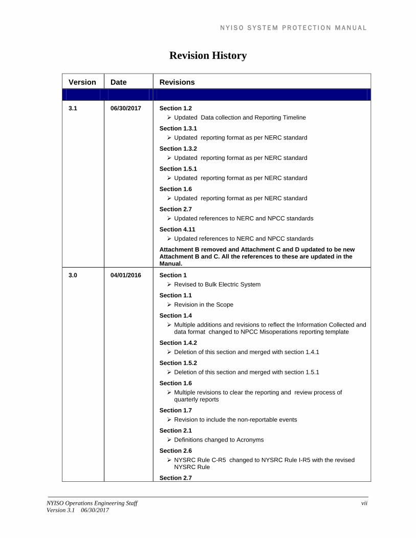
Revision History
Version Date Revisions
3.1 06/30/2017 Section 1.2 Updated Data collection and Reporting Timeline
Section 1.3.1 Updated reporting format as per NERC standard
Section 1.3.2 Updated reporting format as per NERC standard
Section 1.5.1 Updated reporting format as per NERC standard
Section 1.6 Updated reporting format as per NERC standard
Section 2.7 Updated references to NERC and NPCC standards
Section 4.11 Updated references to NERC and NPCC standards
Attachment B removed and Attachment C and D updated to be new Attachment B and C. All the references to these are updated in the Manual.
3.0 04/01/2016 Section 1 Revised to Bulk Electric System
Section 1.1 Revision in the Scope
Section 1.4 Multiple additions and revisions to reflect the Information Collected and
data format changed to NPCC Misoperations reporting template
Section 1.4.2 Deletion of this section and merged with section 1.4.1
Section 1.5.2 Deletion of this section and merged with section 1.5.1
Section 1.6 Multiple revisions to clear the reporting and review process of
quarterly reports
Section 1.7 Revision to include the non-reportable events
Section 2.1 Definitions changed to Acronyms
Section 2.6 NYSRC Rule C-R5 changed to NYSRC Rule I-R5 with the revised
NYSRC Rule
Section 2.7

N Y I S O S Y S T E M P R O T E C T I O N M A N U A L
viii NYISO Operations Engineering Staff Version 3.1 06/30/2017
Revisions made to reflect the current applicable standards
Section 3.6 Deletion of this section
Section 3.3.1 Updated the assumptions for calculating the fault clearing times
Section 4 Multiple edits in Scope
Section 4.1 Multiple additions and revisions to include the applicable entities
Section 4.2 Deletion of old section Addition of Applicable NERC,NPCC and NYSRC standards
Section 4.3 Deletion of old section Addition of UFLS program
Section 4.4 Deletion of old section Addition of Applicable entities actions to conform the UFLS program
Section 4.5 Deletion of old section Addition of Methodology
Section 4.6 Deletion of old section Addition of UFLS program Performance requirements
Section 4.7 Addition of Criteria to meet the UFLS program design performance
characteristics
Section 4.8 Addition of UFLS program assessment requirements
Section 4.9 Addition of Format for UFLS data submittal
Section 4.10 Addition of UFLS Schedule
Section 4.11 Multiple edits to reflect the updated applicable standards
Section 5 Deletion of this section as Maintenance reporting is no longer under
the scope of SPAS
Appendix A Renamed to Attachment A
Appendix B Renamed to Attachment B Deletion of the old format instructions Addition of the NPCC Misoperations reporting Template

N Y I S O S Y S T E M P R O T E C T I O N M A N U A L
NYISO Operations Engineering Staff ix Version 3.1 06/30/2017
Appendix C Renamed to Attachment C
Appendix D Renamed to Attachment D Updated Table D.1 as per the revised scope
2.0 12/31/2013 Section 2 Multiple additions and revisions on DME and DDR specifications for
NYCA
Section 3 Multiple edits reflecting clear abbreviations and reclosing statements
clarifications
Section 4 Updated Table 1 for UFLS as per latest NPCC D-12
Section 5 Multiple edits reflecting dates of data collection
Appendix B.2 Clarification
Appendix D Addition
1.1 8/4/2011 Section 1 Multiple edits reflecting change in scope of NERC/NPCC requirements
Section 2.2 Clarifying edit
Section 3.4.4.1 Additional reporting requirements listed
Section 3.4.4.5 UTC contact information updated
Section 4.2 NPCC D-12 email schedule modification
Section 4.6 Reference to NPCC B-7 removed
Appendix B.2 clarification
1.0 10/29/2009 Initial Release

N Y I S O S Y S T E M P R O T E C T I O N M A N U A L
x NYISO Operations Engineering Staff Version 3.1 06/30/2017
This page intentionally blank.

N Y I S O S Y S T E M P R O T E C T I O N M A N U A L
[Type text]
1. REPORTING TRANSMISSION AND GENERATION PROTECTION SYSTEM OPERATIONS AND PROTECTION SYSTEM PERFORMANCE
The processes outlined below are intended to fulfill information sharing for Bulk Electric System (BES) protection system operations as assigned to the New York Independent System Operator (NYISO) System Protection Advisory Subcommittee (SPAS).
1.1 Scope The NYISO SPAS has the responsibility to exchange information on the design, operation, maintenance, and testing of BES protection equipment and associated communication channels as needed. SPAS reviews BES Protection System Performance (PSP) and maintains a record of all BES protection system misoperations.
1.2 Data Collection and Reporting NYISO staff facilitates the data collection and review of the results with the New York Control Area (NYCA) Transmission and Generation Owners on a quarterly basis.
Each quarter's misoperations reports will be reviewed and discussed in the meeting of the following quarter. On or about the 20th day of the last month of each quarter, NYISO staff shall initiate a reminder via e-mail to those individuals identified by each BES Transmission Owner and Generation Owner as their PSP contact. The reminder shall set forth the collection schedule. The collection schedule is normally as outlined in the following two subsections.
1.2.1 Transmission Owner Collection Schedule PSP data for each quarter shall be transmitted to NYISO staff by e-mail on or before the 20th of the month that follows each quarter.
1.2.2 Generation Owner Collection Schedule Generation Operations data for each quarter shall be transmitted to NYISO staff by e-mail on or before the 20th of the month that follows each quarter.
1.3 Transmission of Data and Discussion of Results The quarterly data is then tabulated and distributed to SPAS for review at the next regularly scheduled SPAS meeting. For this reason, SPAS meetings are normally scheduled shortly after the PSP data is due. This schedule may be adjusted in some quarters due to constraints such as conflicting meetings.

N Y I S O S Y S T E M P R O T E C T I O N M A N U A L
[Type text]
1.3.1 Transmission Owners Each Transmission owner representative shall submit all reportable misoperations for the previous quarter in the section 1600 NERC MIDAS format . At the SPAS meeting, misoperations of particular interest may be discussed within the group.
1.3.2 Generation Owners Generation Owner representatives are encouraged to attend the SPAS meetings to discuss their operations; however, due to the relatively few generation-related protective system operations, it is acceptable for the Generation Owners to simply submit a the section 1600 NERC MIDAS format and be available by phone to discuss the operations, if deemed necessary by NYISO staff and/or the SPAS. NYISO staff shall summarize the results from the previous quarter and provide a verbal report on any operation judged to be incorrect.
1.4 Information Collected and Data Format
1.4.1 Transmission Owners and Generation Owners As a minimum, the following information shall be reported:
Resubmittal check Regional Entity Entity Name NERC ID Misoperation Date Misoperation Time Time Zone Facility Name Equipment Name Equipment Type Facility Voltage Equipment removed from Service Event Description Misoperation Category Causes of Misoperation Incorrect setting/logic/Design Errors and Relay failures / Malfunctions sub-
cause code Protection Systems/Components that Misoperated Relay Technology TADS reportable event and its Event IDs, if applicable Generator Forced outage, if any Analysis and Corrective Action Status

N Y I S O S Y S T E M P R O T E C T I O N M A N U A L
[Type text]
Corrective Action Plan Target Completion Date Actual Completion Date Name of Individual Making Report Phone Email Date of Report
Collection methods are subject to updates and revisions as required.
1.5 Data Collection
1.5.1 Transmission Owners and Generation Owners New York State Transmission Owners shall use the section 1600 NERC MIDAS reporting template to transmit the PSP data to the NYISO.
Collection methods are subject to updates and revisions as required.
1.6 Follow-Up Actions NYISO staff will archive the PSP reports as they are received in advance of each SPAS meeting and shall present the summarized PSP reports for discussion during the SPAS meetings.
Any items that are incomplete or remaining under investigation should be included in the next quarter's template as per the section 1600 NERC MIDAS format.
1.7 Non-NPCC Reportable Events Any other event that would be of interest to the NYISO or SPAS could be reported as supplemental, outside of the reporting as described above.
N Y I S O S Y S T E M P R O T E C T I O N M A N U A L
[Type text]
This page intentionally blank.

N Y I S O S Y S T E M P R O T E C T I O N M A N U A L
NYISO Operations Engineering Staff 2-1 Version 3.1 06/30/2017
2. APPLICATION OF DISTURBANCE MONITORING EQUIPMENT (DME)
Disturbance Monitoring Equipment (DME) as used in this document includes, but is not necessarily limited to, dynamic disturbance recorders, digital fault recorders, and Phasor Measurement units.
The NYCA has long been a pioneer in the effective application of DME and continues to be exemplary in its ability to effectively use DME to accomplish the three main purposes: (1) model validation, (2) disturbance investigation, and (3) assessment of system protection performance.
The NYCA has also been an active participant in preparation of the various DME-related documents of the IEEE, North American Electric Reliability Corporation (NERC), the Northeast Power Coordinating Council, Inc. (NPCC), and the New York State Reliability Council (NYSRC); several of the most important documents are listed in the Section 2.7, “References,” below. This Manual addresses only those items that are not already covered in the applicable documents of NERC, NPCC, and NYSRC.
2.1 Acronyms DDR – Dynamic Disturbance Recorder
DFR – Digital Fault Recorder
DME – Disturbance Monitoring Equipment
GO – Generation Owner
NYISO – The New York Independent System Operator PDC – Phasor Data Concentrator
PMU – Phasor Measurement Unit
TO – Transmission Owner
2.2 Specifications of DDR
2.2.1 Location DDR locations within NYCA must be identified to provide a minimum of one DDR per 3,000 MW of peak load and record dynamic disturbance information. The following eleven (11) DDR locations were determined considering the NERC PRC-002-NPCC-01 R7 criteria as reported in "NYISO Dynamic Disturbance Recorder Location Study":
Niagara 345 kV Pleasant Valley 345 kV Ramapo 345 kV Goethals 345 kV

N Y I S O S Y S T E M P R O T E C T I O N M A N U A L
2-2 NYISO Operations Engineering Staff Version 3.1 06/30/2017
New Scotland 345 kV Edic 345 kV Clay 345 kV Sprain Brook 345 kV Moses 230 kV Rochester 345 kV Stolle Rd. 230 kV
2.2.2 Capabilities DDRs within NYCA shall have the following dynamic disturbance recording capabilities:
Function as continuous recorders. A minimum recording time of sixty (60) seconds per trigger event. A minimum sample rate of 960 samples per second, and a minimum data
storage rate for RMS quantities of six (6) data points per second. DDRs shall be set to trigger for at least one of the following:
• Rate of change of frequency (recommended ±30 mHz/s). • Rate of change of power (recommended ±5 MW/s). • Delta frequency (recommended ±20 mHz). • Delta voltage (recommended ±0.05 Vpu). • Oscillation of frequency (recommended 0 to 3 Hz).
2.2.3 Monitored or Derived Quantities DDRs within NYCA shall monitor or derive the following dynamic disturbance quantities:
Line currents for most lines such that normal line maintenance activities do not interfere with the DDR functionality.
Bus voltages such that normal bus maintenance activities do not interfere with the DDR functionality.
As a minimum, one phase current per monitored Element and two phase-to-neutral voltages of different Elements. One of the monitored voltages shall be of the same phase as the monitored current.
Frequency. Real and reactive power. If derived, shall be calculated using the appropriate bus voltages and line current
pairs.
2.2.4 PMUs within NYISO Network PMUs within the NYISO network currently providing data to the NYISO PDCs are considered in compliance with the DDR requirements of NERC PRC-002-NPCC-01 when

N Y I S O S Y S T E M P R O T E C T I O N M A N U A L
NYISO Operations Engineering Staff 2-3 Version 3.1 06/30/2017
local storage of monitored or recorded data is provided and if the above DDR specifications are met.
2.3 Time Zone The NYISO prefers that DDRs and DFRs be set to Universal Time Zone (identified as UTC).
In the event DDRs and/or DFRs are set to local time, records transmitted to the NYISO shall contain the hours offset from UTC in the file name consistent with the IEEE C37.232 Standard.
2.4 Survey of DME Equipment NYISO staff shall survey the status of DME in the NYCA approximately every two years. This activity shall be coincident with a NPCC survey if a NPCC survey is undertaken. The following DME survey data may be included but not limited to:
Type of DME Recording and triggering capabilities Type of data storage (local or remote) Equipment owner DME recorded data owner Make and model of equipment Power system location of DME Operational Status Monitored elements All identified channels Monitored and derived quantities Trigger settings Date of last maintenance testing
2.5 Sharing of DME Data Through applicable NYISO Tariffs and Market Participant agreements, the NYISO has the right to ask for any DME records or data needed to fulfill its functions as Reliability Coordinator. When necessary, the NYISO will request individual DME records or files from TOs and GOs and DME records must be provided within thirty (30) days from receipt of a request, see Attachment C for collection date. DME records shall contain all monitored channels including analog and binary.
Individual records/files furnished as part of a disturbance investigation shall be in IEEE COMTRADE format (IEEE C37.111), and file names shall be in accordance with IEEE C37.232 convention, except by agreement among the parties involved. Depending on the volume of data, the NYISO may request individual records be forwarded electronically or

N Y I S O S Y S T E M P R O T E C T I O N M A N U A L
2-4 NYISO Operations Engineering Staff Version 3.1 06/30/2017
that a group of files or records be placed on a CD or DVD and shipped to the NYISO by express delivery service.
2.6 Other DFRs shall automatically extend records when a re-trigger occurs while a recording is in progress.
It is recommended that any new DME to be installed at a NYISO-secured Transmission System facility that functions as a DFR or DDR shall have PMU-capability for future use.
DME installed by New York TOs and GOs shall be operated and maintained in accordance with the requirements of NERC Standard PRC-002-2, NPCC Directory 11, NYSRC Rule I-R5 and NERC Standard PRC-018-1. Consideration shall be given to consultation with NYISO staff in regard to DME locations and configuration.
2.7 References NYSRC Rule I.5 “Disturbance Recording” NPCC Directory 11, “Disturbance Monitoring Equipment Criteria” NERC Standard PRC-002-2, " Disturbance Monitoring and Reporting
Requirements" NERC Standard PRC-018-1, “Disturbance Monitoring Equipment Installation
and Data Reporting” NPCC Directory 11 Appendix A, “Guide to Time Synchronization of Substation
Equipment” NPCC Directory 11 Appendix B, “Guide for Application of Disturbance
Recording Equipment” IEEE C37.111-1999, “IEEE Standard for Common Format for Transient Data
Exchange (COMTRADE) for Power Systems” IEEE C37.232-2007, “IEEE Recommended Practice for Naming Time
Sequence Data Files” NYISO Dynamic Disturbance Recorder Location Study, August 26, 2013

N Y I S O S Y S T E M P R O T E C T I O N M A N U A L
NYISO Operations Engineering Staff 3-1 Version 3.1 06/30/2017
3. SYSTEM PROTECTION DATA Transmission system protection data is required to develop and maintain functional models of the transmission and generation NYISO-secured Transmission System facilities or Table A1 of NYISO Outage Scheduling Manual (http://www.nyiso.com/public/markets_operations/documents/manuals_guides/index.jsp) protection devices that can be used for dynamic simulation and for the coordination of protection facilities with the existing and proposed system reinforcements. Some of the data is also required for other aspects of power system operation and operating studies, such as thermal and voltage contingency analysis. This section describes the requirements and procedures for reporting this data to the NYISO.
Facility Equipment owners’ system protection engineering staff shall provide data to the NYISO System Protection Data Coordinator upon request. In general, the time period allowed for such data request is 45 days; however, in special circumstances, a shorter time period may be necessary. Characteristics of protection equipment associated with NYISO-secured Transmission System facilities or Table A1 of NYISO Outage Scheduling Manual are important for dynamic simulation and other aspects of NYISO planning and operations which will be collected and surveyed annually by the NYISO Planning group.
3.1 Relay Characteristics Protection systems may be specifically (rather than generically) modeled when they could operate within the scope of system dynamic simulations (power system stability analyses). When the actual relay system characteristics are not available, a generic relay model may be used. When appropriate, over-current or out-of-step protection may also be modeled. A simplified data submission form is included in this manual as the B.1 Relay Characteristics Form, found on page B-2.
Relay characteristics are required only for relays that could trip for an apparent three-phase fault (e.g., a power swing) to evaluate the possibility of additional trips during the post-transient swing following the clearing of the fault.
Relay characteristics are not used for the purpose of determining clearing times or for the primary clearing of a fault, in the dynamic simulation. Appropriate clearing times are determined by the design of the protection groups on each transmission facility and are reported separately. Please see the B.2 Clearing Times Form, included in this manual on page B-4.
Margins should not be applied to the relay characteristic data. In the course of the study analyses, margins may be applied to the relay characteristics when relay actions are evaluated as part of a stability simulation.
3.2 Pilot Protection Systems Pilot protection systems are defined as those systems that utilize a communications channel in comparing fault conditions at the line terminals of a transmission line to determine whether the fault is internal or external to that particular line section.
N Y I S O S Y S T E M P R O T E C T I O N M A N U A L
3-2 NYISO Operations Engineering Staff Version 3.1 06/30/2017
The procedures described in this manual shall be used by the Transmission Owners to prepare and submit the protection systems relay characteristics data to the NYISO. The relay data shall be furnished on the B.1 Relay Characteristics Form, found on page B-2. If the relay schemes do not lend themselves to this form (only Mho-distance or reactance-distance relays), separate pages shall be attached. If the Facility Equipment owner is using the Power Technologies, Inc. PSS/E program, then PSS/E input forms may be attached to the B.1 Relay Characteristics Form.
3.3 Clearing and Reclosing Times Estimated protection system clearing times and automatic reclosing times are required for all NYISO-secured Transmission System facilities or Table A1 of NYISO Outage Scheduling Manual
3.3.1 Clearing Times Facility Equipment owners shall use the following assumptions when calculating the fault clearing times to be submitted to the NYISO:
Maximum system short-circuit capacity. Faults are solid, three-phase faults. Use both near-end and far-end line faults. Speed of operation of circuit breakers and relay equipment is the nominal speed
quoted by the manufacturer. Clearing time is a single value, from fault inception until breaker clearing. For pilot systems, communication time is included for far-end faults. No margin shall be added to the clearing times. Clearing times for single phase to ground faults may be requested by NYISO
staff when needed.
3.3.2 Reclosing Times The following information is required by the NYISO for reclosing relay protection data:
High speed reclosing times Relay reclosing time in seconds Breaker reclosing time in cycles Delayed reclosing times in seconds First Shot: Hot-bus/dead-line reclosing time in seconds Second Shot: Hot-bus/dead-line reclosing time in seconds Third Shot: Hot-bus/dead-line reclosing time in seconds
A data submission form is included in this manual as the B.3 Reclosing Data Form, found on page B-5. Reclosing terms are used as defined in the NPCC document, “Guide for the Application of Auto Reclosing to the Bulk Power Systems,” Document B-1.
N Y I S O S Y S T E M P R O T E C T I O N M A N U A L
NYISO Operations Engineering Staff 3-3 Version 3.1 06/30/2017
3.4 Special Protection Systems Protection-based systems that are designed to monitor special system conditions can have an impact on system operation. The NYISO requires that the following protection systems be described and reported to the NYISO according to the guidelines of this section:
Special Protection Systems (NPCC definition) Other Remedial Action Systems (NYISO definition)
3.4.1 Special Protection Systems An SPS is defined by NPCC as a protection system designed to detect abnormal system conditions and take corrective action other than the isolation of faulted elements.
Facility Equipment owners are required to prepare and submit to the NYISO an SPS description that includes but is not limited to the following information about the SPS:
Initiating incident (SPS trigger or triggers) Resulting action Total clearing time Reason for use Percent of time in service NPCC classification
This information shall be provided by the Facility Equipment owner’s System Protection Advisory Subcommittee (SPAS) member or designee to the NYISO System Protection Data Coordinator in accordance with NPCC Criteria.
An SPS description shall be prepared for any SPS that is located within the NYCA or involves any ISO-secured facility or tie line between the NYCA and a neighboring control area.
The NPCC Task Force on System Protection maintains an SPS list that is updated and posted annually by NPCC.
3.4.2 Other Remedial Action Systems In addition to NPCC SPSs, NYISO TOs, GOs, Load-Serving Entities (LSEs), or other participants may operate other remedial action systems that are similar in concept to SPSs and that may have an effect on NYCA operations, even though the scheme does not fit the NPCC definition of an SPS. These systems must also be described and reported to the NYISO. Some examples of protection systems could have an effect on NYCA operations are:
A protection system included in transient stability simulations that effects the results of the simulation
A protection system that causes a change in operating limits A protection system used by a Facility Equipment owner that allows the
Transmission Provider to mitigate a transmission security limitation

N Y I S O S Y S T E M P R O T E C T I O N M A N U A L
3-4 NYISO Operations Engineering Staff Version 3.1 06/30/2017
A protection system that limits the ability to load a facility to rated Short-Term Emergency (STE) capability
The NYISO System Protection Data Coordinator notifies the Facility Equipment owner SPAS Member when one of the above situations is detected and a NYISO System Impacting Protection Memo System report is required.
3.4.3 SPS Data Submission and Updating Procedures The following procedures apply to all data described in the Sections 3.4.1 and 3.4.2 unless otherwise indicated.
3.4.3.1 Facility Equipment Owner Actions
1. Submit to the NYISO System Protection Data Coordinator updates to the following data for all facilities found to be Bulk Power system facilities by NPCC criteria A-10, upon the implementation of a new System Impacting Protection System, or upon NYISO request: a. Relay characteristics using the B.1 Relay Characteristics Form found on page B-
2 of this manual. b. Clearing times using the B.2 Clearing Times Form, found on page B-4 of this
manual. c. Reclosing times using the B.3 Reclosing Data Form, found on page B-5 of this
manual.
2. Submit to the NYISO System Protection Data Coordinator the SPS report at least three months before placing the SPS in service.
3. Submit SPS data for all new or modified transmission facilities not later than three months prior to the scheduled in-service date of the protection system. If setting changes are made, the data shall be furnished upon implementation.
4. In the case of transmission lines which are interconnections with neighboring control areas, the TO SPAS representative shall submit data for all terminals of the line.
3.4.3.2 NYISO Actions
1. Once each year the NYISO System Protection Data Coordinator will transmit all data back to each TO SPAS Representative for confirmation or revision.
2. Use the SPS data in the dynamic simulation, thermal, and voltage contingency analysis studies.
3. Inform the Facility Equipment owner SPAS member when SPS conditions are present and a new report is needed.
4. When the review is complete, the NYISO shall issue updates to the NYISO Protection Memo document and distribute to appropriate Facility Equipment owner and NYISO personnel.
N Y I S O S Y S T E M P R O T E C T I O N M A N U A L
NYISO Operations Engineering Staff 3-5 Version 3.1 06/30/2017
3.5 Power Line Carrier Frequencies This section describes the procedure for coordination of Power Line Carrier (PLC) Frequencies among Facility Equipment owners of NYISO and neighboring systems. As part of the coordination process, information is provided for updating PLC databases maintained by the Utilities Telecommunications Council.
3.5.1 Introduction Coordination of PLC frequencies within New York State is the responsibility of the NYISO successor group to the System Protection Advisory Subcommittee (SPAS).
In order to carry out these coordination responsibilities, the NYISO participates as part of a working group known as the Power Line Carrier Task Force, or PLC Task Force. This task force comprises designated Utilities Telecommunications Council PLC Data Base Contacts and the NYISO System Protection Data Coordinator.
The PLC Task force originally collected and supplied information on New York PLC facilities to NERC, which later turned over to UTC the responsibility of maintaining the PLC Database.
3.5.2 Utilities Telecommunications Council PLC Task Force Contacts
Each Facility Equipment owner designates a PLC Task Force contact to represent it. A list of the New York PLC Task Force contacts is maintained by the NYISO.
This list is distributed annually to all PLC Task Force contacts and to SPAS. Changes to this list must be reported by the Equipment owner contact to the NYISO contact and System Protection Data Coordinator as soon as possible. The NYISO will report such changes to the SPAS and all PLC Task Force contacts.
3.5.3 Utilities Telecommunications Council PLC Frequencies Database Reports
Two Utilities Telecommunications Council PLC Frequencies Database reports are available by contacting the Utilities Telecommunications Council. Turnaround time for receipt of any of the reports is approximately three working days.
Individual Organization Report — Details an individual organization’s PLC frequencies. The PLC Frequency data is sorted by substation, transmitter and associated receiver(s), and frequencies.
Interference Report — Details any PLC or licensed user frequencies that are within potential interference distance or frequency range of a proposed or in-use PLC frequency. The criteria used for interference distance is 50 miles.

N Y I S O S Y S T E M P R O T E C T I O N M A N U A L
3-6 NYISO Operations Engineering Staff Version 3.1 06/30/2017
3.5.4 Utilities Telecommunications Council PLC Frequency Coordination Procedures
The PLC frequency coordination procedure applies in the following cases: To request addition of a new PLC frequency for immediate or future use To request a current frequency change
In all these cases, the PLC Frequency Data Report form is completed and sent to the NYISO. The instructions for forms PLC1 and PLC2, and the forms themselves, are available on the Utilities Telecommunications Council Web site at this address: http://www.utc.org/utc/plc-forms-instructions
All the information on Form PLC2 form must be completed, and the applicable Utilities Telecommunications Council Transaction Code for this form must be specified. All transmitter information entered for the first time shall be designated as transaction code A or P.
Add in service A
Add in proposed P
Correction C
Delete D
3.5.4.1 PLC Task Force Contact Actions The Facility Equipment owner PLC Task Force contact shall initiate the process by submitting a completed PLC Frequency Data Report and forwarding such report to the NYISO. The form shall be completed to indicate each new frequency or change. Additionally, a Single-Line Sketch shall be submitted that identifies:
Station and Station ID Line Number Transmitter/Receiver ID and its associated frequency Associated Communication Scheme (DCB, DCUB, DTT, Etc.) to be added or
deleted
Example
DCUB T15 XMIT 224 kHz R15 RCVR 222 kHz
DCUB T09 XMIT 222 kHz R09 RCVR 224 kHz
DTT T16 XMIT 98 kHz R16 RCVR 96 kHz
DTT T10 XMIT 96 kHz R10 RCVR 98 kHz
LN1-16
Station X Station ID: 523
Station Y Station ID: 297

N Y I S O S Y S T E M P R O T E C T I O N M A N U A L
NYISO Operations Engineering Staff 3-7 Version 3.1 06/30/2017
3.5.4.2 NYISO Actions Upon receiving a completed PLC Frequency Data Report, the NYISO shall send copies of the report to the PLC Task Force Contacts.
3.5.4.3 PLC Task Force Contact Actions
1. Within 31 days of receipt of a new PLC Frequency Data Report, each PLC Task Force contact shall advise the NYISO by written memorandum of the concurrence or objection with the proposed PLC frequency or frequencies.
2. If there is a conflict, the involved parties shall attempt to work out the difficulty by holding meetings, where necessary, to negotiate solutions to PLC frequency coordination problems.
3. If the approved frequencies resulting from these discussions are different than those originally submitted, the appropriate PLC Task Force contact shall resubmit a revised PLC Frequency Data Report to the NYISO for redistribution to the PLC Task Force Contacts.
3.5.4.4 NYISO Actions When frequencies are found satisfactory by all PLC Task Force contacts, the NYISO shall notify the Facility Equipment owner of this result.
3.5.4.5 PLC Task Force Contact Actions The Facility Equipment owner PLC Task Force contact that originated the Frequency Report shall send it to the current designated contact at the Utilities Telecommunications Council. At this time the address is as follows:
Donald Vasek Director of Spectrum Services Utilities Telecom Council 1129 20th St NW #350 Washington, DC 20036 [email protected]
Tel. No.: 202-833-6814
3.5.4.6 Utilities Telecommunications Council Actions Upon receiving the PLC Frequency Data Report, the Utilities Telecommunications Council will report other potential conflicts to the affected Facility Equipment owner PLC Task Force contacts.
If the transaction code was to add a proposed new frequency (P), Utilities Telecommunications Council will report on potential conflicts to the affected Transmission Provider Contact only and not to other users of the low-frequency radio spectrum.

N Y I S O S Y S T E M P R O T E C T I O N M A N U A L
3-8 NYISO Operations Engineering Staff Version 3.1 06/30/2017
If the transaction code was to add a frequency already in service, Utilities Telecommunications Council will report the potential conflict to all the PLC Task Force contacts and users of the low-frequency radio spectrum.
3.5.5 Procedures for Retiring PLC Frequencies When Facility Equipment owners decide to retire a PLC frequency from the Utilities Telecommunications Council PLC database, the same PLC Frequency Data Report is submitted to the NYISO. In this case the applicable Utilities Telecommunications Council Transaction Code is:
Code D, standing for “deletion of an existing PLC frequency.”
It is not necessary for the Facility Equipment owner’s PLC Task Force contact to respond to the NYISO in the case of retired frequencies.
3.5.5.1 PLC Task Force Contact Action Initiate the process by submitting a completed PLC Frequency Data Report to the NYISO. This form shall be completed to indicate each frequency retired. A copy of this form shall be sent to the Utilities Telecommunications Council at the address above.
3.5.5.2 NYISO Action Upon receiving a completed PLC Frequency Data Report, the NYISO shall send copies of the report to the PLC Task Force contacts.
3.5.6 Annual Review of the PLC Frequencies Database In addition to the coordination and database update procedures defined, an annual review is required of the Utilities Telecommunications Council database for accuracy.
3.5.6.1 Utilities Telecommunications Council Action Annually, Utilities Telecommunications Council initiates the review of the PLC Frequencies Database by sending to each PLC Task Force contact a copy of their respective Utilities Telecommunications Council data for review.
3.5.6.2 PLC Task Force Contact Actions
1. Review and revise the Utilities Telecommunications Council database and send it directly to the Utilities Telecommunications Council.
2. Send copies of the PLC Database revisions to the NYISO.
3.5.6.3 NYISO Action Send copies of received PLC Frequencies Database updates to all of the other PLC Task Force contacts.

N Y I S O S Y S T E M P R O T E C T I O N M A N U A L
NYISO Operations Engineering Staff 4-1 Version 3.1 06/30/2017
4. AUTOMATIC UNDERFREQUENCY LOAD SHEDDING REPORTING AND COMPLIANCE
The NYISO Underfrequency Load Shedding (UFLS) program is developed as per the NERC Standard PRC-006-2 Automatic Underfrequency Load Shedding objective to establish design and documentation requirements for automatic UFLS programs to arrest declining frequency, assist recovery of frequency following underfrequency events and provide last resort system preservation measures.
4.1 Applicability
4.1.1 Planning Coordinator The NYISO is the Planning Coordinator for the NYCA.
4.1.2 UFLS Entities NYCA Generator Owners NYCA Transmission Owners NYCA Distribution Providers or Municipals.
4.2 Applicable Standards NERC Standard PRC-006-2 – “Automatic Underfrequency Load Shedding” NPCC Standard PRC-006-NPCC-1- “Automatic Underfrequency Load
Shedding” NPCC Directory -2 – “Emergency Operations” NPCC Directory -12 – “Automatic UFLS Program Requirements” NYSRC Reliability Rule D.2 – “Underfrequency Load Shedding”
4.3 UFLS Program The intent of the NYISO Automatic Under Frequency Load Shedding program is to ensure that declining frequency is arrested and recovered in accordance with established performance requirements.
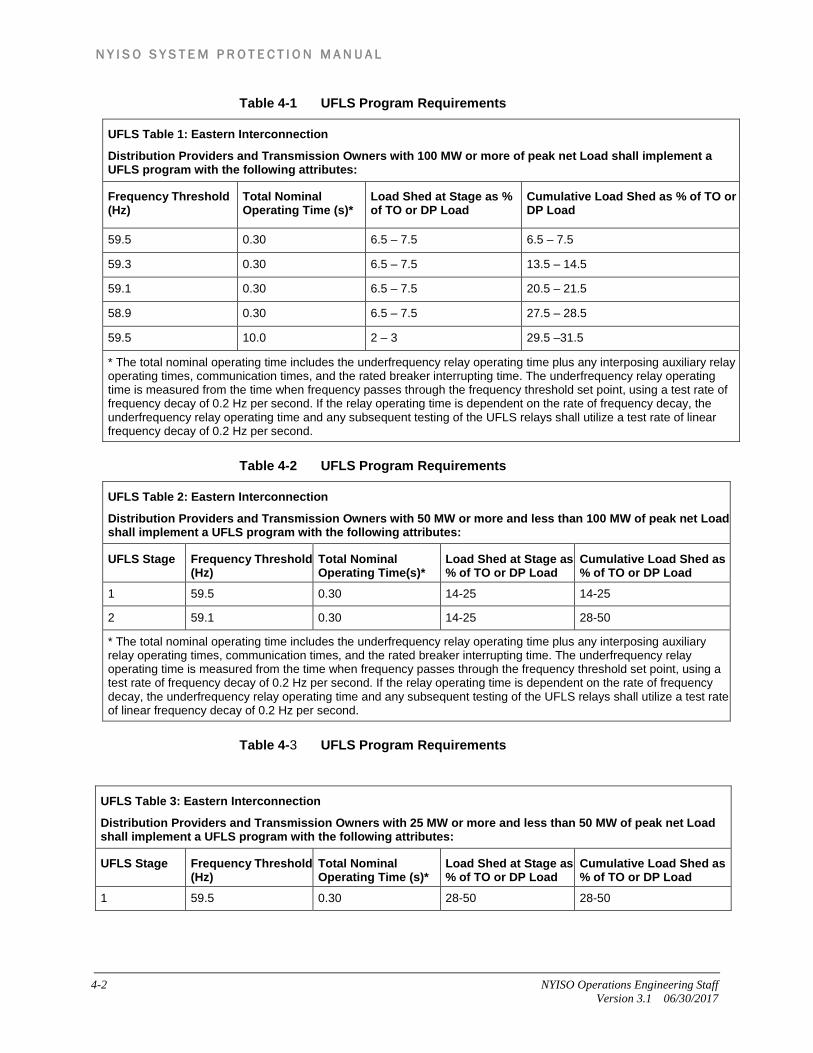
4.3.1 Underfrequency Load Shedding Program Requirements The UFLS entities shall implement an automatic UFLS program reflecting normal operating conditions excluding outages for its Facilities based on frequency thresholds, total nominal operating time and amounts specified as per Table 4-1 through Table 4-3 as shown below. [Ref :NPCC Standard PRC-006-NPCC-1 Attachment C]
N Y I S O S Y S T E M P R O T E C T I O N M A N U A L
4-2 NYISO Operations Engineering Staff Version 3.1 06/30/2017
Table 4-1 UFLS Program Requirements
UFLS Table 1: Eastern Interconnection
Distribution Providers and Transmission Owners with 100 MW or more of peak net Load shall implement a UFLS program with the following attributes:
Frequency Threshold (Hz)
Total Nominal Operating Time (s)*
Load Shed at Stage as % of TO or DP Load
Cumulative Load Shed as % of TO or DP Load
59.5 0.30 6.5 – 7.5 6.5 – 7.5
59.3 0.30 6.5 – 7.5 13.5 – 14.5
59.1 0.30 6.5 – 7.5 20.5 – 21.5
58.9 0.30 6.5 – 7.5 27.5 – 28.5
59.5 10.0 2 – 3 29.5 –31.5
* The total nominal operating time includes the underfrequency relay operating time plus any interposing auxiliary relay operating times, communication times, and the rated breaker interrupting time. The underfrequency relay operating time is measured from the time when frequency passes through the frequency threshold set point, using a test rate of frequency decay of 0.2 Hz per second. If the relay operating time is dependent on the rate of frequency decay, the underfrequency relay operating time and any subsequent testing of the UFLS relays shall utilize a test rate of linear frequency decay of 0.2 Hz per second.
Table 4-2 UFLS Program Requirements
UFLS Table 2: Eastern Interconnection
Distribution Providers and Transmission Owners with 50 MW or more and less than 100 MW of peak net Load shall implement a UFLS program with the following attributes:
UFLS Stage Frequency Threshold (Hz)
Total Nominal Operating Time(s)*
Load Shed at Stage as % of TO or DP Load
Cumulative Load Shed as % of TO or DP Load
1 59.5 0.30 14-25 14-25
2 59.1 0.30 14-25 28-50
* The total nominal operating time includes the underfrequency relay operating time plus any interposing auxiliary relay operating times, communication times, and the rated breaker interrupting time. The underfrequency relay operating time is measured from the time when frequency passes through the frequency threshold set point, using a test rate of frequency decay of 0.2 Hz per second. If the relay operating time is dependent on the rate of frequency decay, the underfrequency relay operating time and any subsequent testing of the UFLS relays shall utilize a test rate of linear frequency decay of 0.2 Hz per second.
Table 4-3 UFLS Program Requirements
UFLS Table 3: Eastern Interconnection
Distribution Providers and Transmission Owners with 25 MW or more and less than 50 MW of peak net Load shall implement a UFLS program with the following attributes:
UFLS Stage Frequency Threshold (Hz)
Total Nominal Operating Time (s)*
Load Shed at Stage as % of TO or DP Load
Cumulative Load Shed as % of TO or DP Load
1 59.5 0.30 28-50 28-50

N Y I S O S Y S T E M P R O T E C T I O N M A N U A L
NYISO Operations Engineering Staff 4-3 Version 3.1 06/30/2017
4.3.2 Generator Underfrequency Protection Requirements Generators shall not be tripped for under frequency conditions in the area above the curve in Figure 4-1, except for the following:
In Special cases, requirements may dictate generator to trip in the region above the curve in Figure 1. In those cases, the Generator Owners shall notify NYISO and shall ensure through alternate arrangements, that automatic load shedding additional to the amount equivalent to +/- 5% to the amount of generation to be tripped is provided and shall be reviewed by the Task Force on Coordination of Operation.
Generator Owners shall not increase the underfrequency trip settings or make other modifications to the existing exempt generators (that trip above the curve in Figure 4-1) that may cause these generators to, directly or indirectly, trip at a higher frequency.
* The total nominal operating time includes the underfrequency relay operating time plus any interposing auxiliary relay operating times, communication times, and the rated breaker interrupting time. The underfrequency relay operating time is measured from the time when frequency passes through the frequency threshold set point, using a test rate of frequency decay of 0.2 Hz per second. If the relay operating time is dependent on the rate of frequency decay, the underfrequency relay operating time and any subsequent testing of the UFLS relays shall utilize a test rate of linear frequency decay of 0.2 Hz per second.

N Y I S O S Y S T E M P R O T E C T I O N M A N U A L
4-4 NYISO Operations Engineering Staff Version 3.1 06/30/2017
Figure 4-1 Underfrequency Curve for Generators
4.4 Actions to conform the UFLS Program NYISO Actions
The NYISO shall perform the following:
1. The requirements for entities aggregating their UFLS programs for each anticipated island and requirements for compensatory load shedding based on islanding criteria are described within this section. The specific sections would include, but not be limited to, the “Transmission Owners and distribution Providers Actions” , “Generator Owners Actions”, “Transmission Owners, Distribution Owners and Generator Owners actions”, Section 4.5.1, 4.5.23,4.5.5,4.6,4.8,4.9, and 4.10.
2. Within 30 days of completion of its system studies required by the NERC PRC Standard on UFLS, identify to the Regional Entity the generation facilities within its area necessary to support the UFLS program performance characteristics.
3. Provide to the Transmission Owner, Distribution Provider, and Generator Owner within 30 days upon written request the requirements for entities aggregating the UFLS programs and requirements for compensatory load shedding program derived from system studies as determined by 1.
N Y I S O S Y S T E M P R O T E C T I O N M A N U A L
NYISO Operations Engineering Staff 4-5 Version 3.1 06/30/2017
4. Develop and review once per calendar year settings for inhibit thresholds (such as but not limited to voltage, current and time) to be utilized within its region's UFLS program.
5. Provide each Transmission Owner and Distribution Provider the applicable inhibit thresholds within 30 days of the initial determination of those inhibit thresholds and within 30 days of any changes to those thresholds.
6. Maintain a UFLS database containing data necessary to model its UFLS program for use in event analyses and assessments of the UFLS program at least once each calendar year.
7. Provide its UFLS database containing data necessary to model its UFLS program to other Planning Coordinators within its Interconnection within 30 calendar days of request.
8. Update its UFLS program database as specified by the NERC PRC Standard on UFLS. This database shall include the following information:
• Amount and location of load shed at peak, the corresponding frequency threshold and time delay settings for each UFLS relay, including those used for compensatory load shedding.
• Buses at which the Load is modeled in the NPCC library power flow case. • List of all generating units that may be tripped for underfrequency conditions
above the appropriate generator underfrequency trip protection settings threshold curve in Figure 4-1, including the frequency trip threshold and time delay for each protection system.
• Location and amount of additional elements to be switched for voltage control that are coordinated with UFLS program tripping.
• List of all UFLS relay inhibit functions along with the corresponding settings and locations of these relays.
9. Notify each Distribution Provider, Transmission Owner, and Generator Owner of changes to load distribution needed to satisfy UFLS program performance characteristics as specified by the NERC PRC Standard on UFLS.
10. Conduct and document an assessment of BES islanding event in its area that results in frequency excursions below the initializing set points of the UFLS program within one year of event actuation to evaluate the performance and effectiveness of the UFLS program.
11. Conduct and document a UFLS design assessment to consider the deficiencies identified during the event assessment performed in 10 within two years of event actuation.
12. Coordinate with the respective Planning Coordinators the event assessment in 10 if the BES islanding event included areas or portions of area(s) of other Planning Coordinator(s) through one of the following:
• Conduct a joint event assessment per 10 among the Planning Coordinators whose areas or portions of areas were included in the same islanding event, or

N Y I S O S Y S T E M P R O T E C T I O N M A N U A L
4-6 NYISO Operations Engineering Staff Version 3.1 06/30/2017
• Conduct an independent event assessment per 10 that reaches conclusions and recommendations consistent with those of the event assessments of the other Planning Coordinators whose areas or portions of whose areas were included in the same islanding event, or
• Conduct an independent event assessment per 10 and where the assessment fails to reach conclusions and recommendations consistent with those of the event assessments of the other Planning Coordinators whose areas or portions of areas were included in the same islanding event, identify differences in the assessments that likely resulted in the differences in the conclusions and recommendations and report these differences to the other Planning Coordinators whose areas or portions of areas were included in the same islanding event and the ERO.
13. Respond to the written comments submitted by UFLS entities following comment period and before finalizing its UFLS Program, indicating in the written response to comments whether changes will be made or reasons why changes will not be made to the following:
• UFLS Program, including a schedule for Implementation • UFLS design assessment • Format and schedule of UFLS data submittal
Transmission Owners and Distribution Providers Actions
The TOs and DPs shall perform the following:
1. Implement an automatic UFLS program reflecting normal operating conditions excluding outages for its Facilities based on frequency thresholds, total nominal operating time and amounts specified in Tables 1 through 3,or shall collectively implement by mutual agreement with one or more Distribution Providers and Transmission Owners within the same island identified and acting as a single entity, provide an aggregated automatic UFLS program that sheds their coincident peak aggregated net Load, based on frequency thresholds, total nominal operating time and amounts specified in Table 4-1 through Table 4-3 UFLS Program Requirements .
2. Distribution Provider or Transmission Owner that must arm its load to trip on Underfrequency in order to meet its requirements as specified and by doing so exceeds the tolerances and/or deviates from the number of stages and frequency set points of the UFLS program as specified in the Table 4-1 through Table 4-3 UFLS Program Requirements as shown above, as applicable depending on its total peak net Load shall:
• Inform NYISO of the need to exceed the stated tolerances or the number of stages as shown in UFLS Table 4-1 if applicable and
• Provide NYISO with a technical study that demonstrates that the Distribution Providers or Transmission Owners specific deviations from the requirements of UFLS Table 4-1 will not have a significant adverse impact on the bulk power system.

N Y I S O S Y S T E M P R O T E C T I O N M A N U A L
NYISO Operations Engineering Staff 4-7 Version 3.1 06/30/2017
• Inform NYISO of the need to exceed the stated tolerances of UFLS in Table 4-2 or Table 4-3 UFLS Program Requirements , and in the case of Table 4-2 only, the need to deviate from providing two stages of UFLS, if applicable, and
• Provide NYISO with an analysis demonstrating that no alternative load shedding solution is available that would allow the Distribution Provider or Transmission Owner to comply with UFLS Table 4-2 or Table 4-3 UFLS Program Requirements .
3. Set each underfrequency relay with 100ms as minimum time delay.
4. Implement the inhibit threshold settings based on the notification provided by the NYISO.
5. Develop and submit an implementation plan within 90 days of the request from the NYISO for approval by the NYISO.
6. Provide annually the actual net Load that would have been shed by the UFLS relays at each UFLS stage coincident with their integrated hourly peak net load during the previous year, as determined by measuring actual metered loads through switches that would be opened by the UFLS relays.
7. Transmission Owners shall provide automatic switching of its existing capacitor banks, Transmission Lines, and reactors to control over-voltage as a result of underfrequency load shedding if required by the UFLS program and schedule for application determined by NYISO.
Generator Owners Actions
The Generator Owners shall perform the following:
1. Set each generator underfrequency trip relay, if so equipped, below the appropriate generator underfrequency trip protection settings threshold curve in Figure 4-1, except as otherwise exempted.
2. Transmit the generator underfrequency trip setting and time delay to the NYISO within 45 days of the request.
3. For a new generating unit, scheduled to be in service or an existing generator increasing its net capability by greater than 10% shall:
• Design measures to prevent the generating unit from tripping directly or indirectly for underfrequency conditions above the appropriate generator tripping threshold curve in Figure 4-1.
• Design auxiliary system(s) or devices used for the control and protection of auxiliary system(s), necessary for the generating unit operation such that they will not trip the generating unit during underfrequency conditions above the appropriate generator underfrequency trip protection settings threshold curve in Figure 4-1.
4. For existing non-nuclear units in service that have underfrequency protections set to trip above the appropriate curve in Figure 4-1 shall:

N Y I S O S Y S T E M P R O T E C T I O N M A N U A L
4-8 NYISO Operations Engineering Staff Version 3.1 06/30/2017
• Set the underfrequency protection to operate at the lowest frequency allowed by the plant design and licensing limitations.
• Transmit the existing underfrequency settings and any changes to the underfrequency settings along with the technical basis for the settings to the NYISO.
• Transmit the existing underfrequency settings and any changes to the underfrequency settings along with the technical basis for the settings to the NYISO.
• Have compensatory load shedding, as provided by a Distribution Provider or Transmission Owner that is adequate to compensate for the loss of their generator due to early tripping as per Compensatory Load Shedding Criteria.
5. For the existing nuclear generating plants with units that have underfrequency relay threshold settings above the Eastern Interconnection generator tripping curve in Figure 4-1, based on their licensing design basis, shall:
• Set the underfrequency protection to operate at as low a frequency as possible in accordance with the plant design and licensing limitations but not greater than 57.8Hz.
• Set the frequency trip setting upper tolerance to no greater than + 0.1 Hz. • Transmit the initial frequency trip setting and any changes to the setting and
the technical basis for the settings to the NYISO.
Transmission Owners, Distribution Owners and Generator Owners Actions
The Transmission Owners, Distribution Providers and Generator Owners shall perform the following:
Provide data to NYISO according to the format and schedule specified by NYISO to support maintenance of UFLS database.
Provide automatic tripping of load in accordance with the UFLS program design and schedule for application determined by NYISO.
Apply the Compensatory Load Shedding Criteria within its area to determine the compensatory load shedding that is required for existing non–nuclear generating units in service that have underfrequency protections set to trip above the appropriate curve as shown in Figure 1 that is adequate to compensate for the loss of the generator due to early tripping.
Implement the load distribution changes based on the notification provided by NYISO.
4.5 Methodology
4.5.1 Potential Island Identification UFLS design and assessment is based on simulations performed by the working
group SS 38 of the Task Force on System Studies anticipated electrical island formation.
N Y I S O S Y S T E M P R O T E C T I O N M A N U A L
NYISO Operations Engineering Staff 4-9 Version 3.1 06/30/2017
Island formation is identified by applying extreme or beyond extreme contingency disturbances to force a loss of synchronism within the system. The island formation analysis confirms that forcing a loss of synchronism between coherent generation groups for an all lines in service condition requires simulation of at least an extreme contingency event.
Simulated disturbances include application of three-phase delayed clearing faults using typical breaker failure clearing times or longer (12 cycles or more). They also include loss of a right-of-way (R-O-W), loss of substation, or loss of a generating station following application and clearing of an initiating fault.
Three-phase faults are placed at several different locations across the New York 345 kV system. The faults were applied for a duration exceeding the critical clearing time resulting in a loss of synchronism of a portion of the system.
Additionally, islands can be identified by simultaneously tripping the ties between the identified coherent generation groups, islanding the entire NYISO system, or reproducing a historical event.
The NYISO system is not designed to form any islands as the result of the operation of a relay scheme or a Remedial Action Scheme.
4.5.2 Identification of Generation facilities The SS 38 working group obtains the Governor Modeling information from the NERC survey of unit governing response for the Assessment of Underfrequency Load Shedding Adequacy study. In addition to this the group coordinates with their counterparts on the NPCC CO-1 Control Performance Working Group to incorporate the accurate governor information into the system models. Also the information with respect to individual unit response during frequency deviations along with the NPCC SS-38 Governor Response Calibration Procedure for Dynamics Simulations is used for Generator modeling with better modeling tools.
4.5.2.1 Generation facilities necessary for UFLS program performance
For each Area, SS-38 members consult their counterparts on the NPCC CO-1 Control Performance Working Group to identify any units that are observed to be unresponsive to system off-nominal frequency events. After disabling the governor models for these units the governor droop is adjusted on the remaining non-hydraulic units to match the system frequency response in the study model to the observed system frequency response. Hence the list of generator facilities which are necessary for the UFLS program are identified from the UFLS assessment study.
4.5.2.2 Generation facilities with restrained performance Similarly the generator units those generator output starts to increase as the frequency drops in proportion to frequency deviation, but overriding “outer loop” controls restrains it to return to its initial value (more or less), even though the frequency deviation persists are identified in the UFLS assessment study.

N Y I S O S Y S T E M P R O T E C T I O N M A N U A L
4-10 NYISO Operations Engineering Staff Version 3.1 06/30/2017
4.5.3 Computation of Load The amounts of load shedding shall be reported coincident with the individual UFLS Entity’s integrated hourly peak from the previous summer. That is, the individual UFLS Entity shall total its UFLS circuit loads at the time of the Entity's previous year’s integrated hourly summer peak, and report the amount of load that would have been shed at each UFLS step, in both megawatts and as a percentage of the peak. The calculations shall be retained for a period of two years after making this report.
Aggregation
Entities with less than 100 MW of end-use load connected to its facilities may collectively implement by mutual agreement with one or more entities within the same NYISO identified island an aggregated automatic UFLS program that sheds load based on the frequency thresholds in Table 4-1 section as an alternative to implementing the applicable program in Table 4-2 or Table 4-3 UFLS Program Requirements .
Exemptions
Entities with less than 25 MW of end-use load connected to its facilities are exempt from providing UFLS.
Activation Times
Under frequency threshold relays shall be set to a nominal total operating time of 300 ms, from the time when frequency passes through the set point to the time of circuit breaker contact opening (including any communications time delay), with a minimum relay operating time to be no less than 100 ms when the rate of frequency decay is 0.2 Hz per second.
4.5.4 Inhibits settings The settings for inhibits thresholds such as but not limited to voltage, current and time utilized by the UFLS entities for the UFLS program is reviewed once in every year.
The UFLS Assessment study provides the UFLS requirements for the region and based on this the UFLS entities set inhibits settings. This may require the TOs planning group and relay group to work together to collect the required data.
4.5.5 Compensatory Load Shedding Criteria The Generator Owners in the New York State are responsible for establishing a compensatory load shedding program for all existing non-nuclear units with underfrequency protection set to trip above the appropriate curve in Figure 4-1 of this standard.
The Generator Owner shall follow the methodology below to determine compensatory load shedding requirements:
1. The Generator Owner shall identify and compile a list of all existing non-nuclear generating units in service prior to the effective date of this standard that has

N Y I S O S Y S T E M P R O T E C T I O N M A N U A L
NYISO Operations Engineering Staff 4-11 Version 3.1 06/30/2017
underfrequency protection set to trip above the appropriate curve in Figure 4-1. The list shall include the following information associated with each unit:
• -Generator name and generating capacity • -Underfrequency protection trip settings, including frequency trip set points
and time delays • -Physical and electrical location of the unit • -Smallest island within which the unit may operate as identified by the NYISO
2. For each generating unit identified in (1) above, the Generator Owner shall establish the requirements for compensatory load shedding based on criteria outlined below:
• In cases where a Distribution Provider or Transmission Owner has coordinated protection settings with the Generator Owner to cause the generator to trip above the appropriate curve in Figure 4-1, the Distribution Provider or Transmission Owner is responsible to provide the appropriate amount of compensatory load to be shed within the smallest island identified by the NYISO.
• In cases where a Generator Owner has a generator that cannot physically meet the set points defined by the appropriate curve in Figure 4-1, the Generator Owner shall arrange for a Distribution Provider or Transmission Owner to provide the appropriate amount of compensatory load to be shed within the smallest island identified by the NYISO.
• The compensatory load shedding that is provided by the Distribution Provider or Transmission Owner shall be in addition to the amount that the Distribution Provider or Transmission Owner is required to shed as specified in Figure 4-1.
• The compensatory load shedding shall be provided at the UFLS program stage with the frequency threshold setting at or closest to but above the frequency at which the subject generator will trip.
• The amount of compensatory load shedding shall be equivalent (±5%) to the average net generator megawatt output for the prior two calendar years, as specified by the NYISO, plus expected station loads to be transferred to the system upon loss of the facility. The net generation output should only include those hours when the unit was a net generator to the electric system.
• In the specific instance of a generating unit that has been interconnected to the electric system for less than two calendar years, the amount of compensatory load shedding shall be equivalent (±5%) to the maximum claimed seasonal capability of the generator over two calendar years, plus expected station loads to be transferred to the system upon loss of the facility.
4.6 UFLS Program Performance Requirements The UFLS program shall meet the following performance characteristics in simulations of underfrequency conditions resulting from an imbalance scenario, where an imbalance = [(load — actual generation output) / (load)], of up to 25 percent within the identified island(s).
N Y I S O S Y S T E M P R O T E C T I O N M A N U A L
4-12 NYISO Operations Engineering Staff Version 3.1 06/30/2017
Frequency shall remain above the Underfrequency Performance Characteristic curve as shown in Figure 2, either for 60 seconds or until a steady-state condition between 59.3 Hz and 60.7 Hz is reached, and
Frequency shall remain below the Overfrequency Performance Characteristic curve as shown in Figure 2, either for 60 seconds or until a steady-state condition between 59.3 Hz and 60.7 Hz is reached, and
Volts per Hz (V/Hz) shall not exceed 1.18 per unit for longer than two seconds cumulatively per simulated event, and shall not exceed 1.10 per unit for longer than 45 seconds cumulatively per simulated event at each generator bus and generator step-up transformer high-side bus associated with each of the following: • Individual generating units greater than 20 MVA (gross nameplate rating)
directly connected to the BES. • Generating plants/facilities greater than 75 MVA (gross aggregate nameplate
rating) directly connected to the BES. • Facilities consisting of one or more units connected to the BES at a common
bus with total generation above 75 MVA gross nameplate rating.
4.7 Criteria to Meet the UFLS Program Design Performance Characteristics
NYISO shall conduct and document a UFLS design assessment at least once every five years to determine through dynamic simulation whether the UFLS program design meets the performance characteristics for the identified islands. The simulation shall model each of the following:
Underfrequency trip settings of individual generating units greater than 20 MVA (gross nameplate rating) directly connected to the BES that trip above the Generator Underfrequency Trip Modeling curve as shown in Figure 4-2 Underfrequency Load Shedding ProgramFigure 4-2.
Underfrequency trip settings of generating plants/facilities greater than 75 MVA (gross aggregate nameplate rating) directly connected to the BES that trip above the Generator -Underfrequency Trip Modeling curve as shown in Figure 4-2.
Underfrequency trip settings of any facility consisting of one or more units connected to the BES at a common bus with total generation above 75 MVA (gross nameplate rating) that trip above the Generator Underfrequency Trip Modeling curve as shown in Figure 4-2.
Overfrequency trip settings of individual generating units greater than 20 MVA (gross nameplate rating) directly connected to the BES that trip below the Generator Overfrequency Trip Modeling curve as shown in Figure 4-2.
Overfrequency trip settings of generating plants/facilities greater than 75 MVA (gross aggregate nameplate rating) directly connected to the BES that trip below the Generator Overfrequency Trip Modeling curve as shown in Figure 4-2.
Overfrequency trip settings of any facility consisting of one or more units connected to the BES at a common bus with total generation above 75 MVA

N Y I S O S Y S T E M P R O T E C T I O N M A N U A L
NYISO Operations Engineering Staff 4-13 Version 3.1 06/30/2017
(gross nameplate rating) that trip below the Generator Overfrequency Trip Modeling curve as shown in Figure 4-2.
Any automatic Load restoration that impacts frequency stabilization and operates within the duration of the simulations run for the assessment.
Figure 4-2 Underfrequency Load Shedding Program
4.8 UFLS Program Assessment Requirements Studies shall be performed by the associated Transmission Operator to ensure satisfactory voltage and loading conditions after automatic load shedding.
The Task Force on System Studies shall conduct a study every five years to coordinate the Automatic Underfrequency Load Shedding Program among the NPCC Balancing Authorities in accordance with the NERC standard PRC-006-2 timeline.
4.9 Format of UFLS data submittal A format for reporting compliance will be distributed with the e-mail inquiry. The following information will be reported on this form:
Name of UFLS Entity Date of report Details of the individual making the report on behalf of the Entity Name
N Y I S O S Y S T E M P R O T E C T I O N M A N U A L
4-14 NYISO Operations Engineering Staff Version 3.1 06/30/2017
Title Email address
For Section 5.2.1 of D-12:
Previous year’s summer integrated hourly peak load UFLS at each step, expressed as both megawatts and percentage of Entity’s
peak, including those steps provided that are beyond the NPCC-mandated steps
For Section 5.4 of D-12:
List of generators that do not conform with NPCC D-12. For each such non-conforming generator, the generator megawatt rating, trip
setting in Hertz, and time delay in seconds. Compensatory load shedding for each such non-conforming generator, with the
megawatts load shedding and trip setting in Hertz. Non-conforming generators with a rating below 20 MW may be reported in
groups with other generators of the same settings. Compensatory load shedding for generators that have been reported in groups
may also be grouped. The load-shedding amounts reported for Section 5.2.1 must not include load
shedding provided as compensation for non-conforming generators, in Sections 5.4. That is, the same loading shedding may not be reported for purposes of both 5.2 and 5.4.
For R20 of PRC-006-NPCC-1
List of buses at which the load is modeled in the NPCC library FERC-715 power flow case with PSS/E Bus number, Bus name and Zone number
For each relay, including those used for compensatory load shedding, the amount and location of load shed at peak, the corresponding frequency threshold and time delay settings.
The location and amount of additional elements to be switched for voltage control that are coordinated with UFLS program tripping.
List of all UFLS relay inhibit functions along with the settings and locations of these relays.
Overall Compliance:
A statement of compliance with NPCC D-12
4.10 Schedule of UFLS Data Submittal NYISO shall initiate the request and collect the data and compliance statements as per formats specified in section 4.9 once each calendar year.
N Y I S O S Y S T E M P R O T E C T I O N M A N U A L
NYISO Operations Engineering Staff 4-15 Version 3.1 06/30/2017
4.11 References NPCC D-12, “UFLS Program Requirements,” July 9, 2013, or most recent
version, available at: https://www.npcc.org/Standards/Directories/Directory12%20Full%20Member%20clean%2020150330%20GJD.pdf
PRC-006-NPCC-1, "Automatic Underfrequency Load Shedding," July 1,2015, available at: http://www.nerc.com/files/PRC-006-NPCC-1.pdf
“UFLS Implementation Plan,” June 26, 2009, available at: https://www.npcc.org/Standards/Directories/UFLS%20Directory%2012%20Implementation%20IESO_%20tolerance%20rev%20clean%2020140324_GJD.pdf
NERC Standard PRC-006-2 "Automatic Underfrequency Load Shedding Requirements," available at: http://www.nerc.net/standardsreports/standardssummary.aspx
NYSRC Rule D-R2, “Underfrequency Load Shedding,” available at: http://www.nysrc.org
NPCC Underfrequency Load Shedding Assessment Studies
N Y I S O S Y S T E M P R O T E C T I O N M A N U A L
4-16 NYISO Operations Engineering Staff Version 3.1 06/30/2017
This page intentionally blank.
N Y I S O S Y S T E M P R O T E C T I O N M A N U A L
NYISO Operations Engineering Staff A-1 Version 3.1 06/30/2017
A.
Attachment A. Guide for the Selection of Power Line Carrier Frequencies
This attachment establishes minimum guidelines to provide a uniform method of selecting power line carrier (PLC) frequencies within the New York Control Area (NYCA). Procedures used by the Transmission owners to notify necessary parties of PLC frequency changes and additions and to keep the Utilities Telecommunications Council PLC database current can be found in the Section 3.5.4 of this manual.
PLC spectrum conservation has been a major concern within the power utility business for many years. These guidelines have been developed to conserve spectrum while staying within industry-established frequency separation limits to minimize interference between channels.
It is assumed that the user of this manual is familiar with the application of power line carrier systems.
A periodic review of these guidelines may be necessary, however, as dictated by changes in equipment technology.
A.1. PLC Modulation Techniques Three types of modulation techniques that utilize the PLC frequency spectrum of 10 to 490 kHz are in general use, namely Amplitude Modulated Keyed Systems, Frequent Shift Keyed Systems, and Single Side Band Systems, described in further detail in the following three subsections.
A.1.1. Amplitude Modulated Keyed Systems On-Off amplitude modulated (AM) keyed PLC systems are usually used for blocking relay schemes. This type of system may also serve a second function of transmitting voice over the power lines via AM. The PLC frequency is usually off (no PLC signal transmitted).
A.1.2. Frequent Shift Keyed Systems Frequency shift keyed (FSK) power line carrier systems are used for unblocking and transfer-tripping relay schemes. This type of PLC system always transmits at least one signal, sometimes at reduced levels to avoid possible interference. During tripping operations, full transmitter power (exalted signal level) is used. FSK – PLC systems are generally preferred over AM – PLC systems, as they allow the system to be continuously monitored.
A.1.3. Single Side Band Systems Single side band (SSB) suppressed AM carrier is used for multi-function PLC communications. SSB systems are typically four-channel systems (4-kHz Bandwidth channels). This is done by the “upshifting” of audio tone and/or baseband frequencies to
N Y I S O S Y S T E M P R O T E C T I O N M A N U A L
A-2 NYISO Operations Engineering Staff Version 3.1 06/30/2017
line frequencies. The channels can be used for various functions including relaying (audio tone and/or baseband), voice, telemetry, and SCADA communications.
When considering frequency separation guidelines, the requirements of both the SSB – PLC system as well as the specific needs of the communications systems utilizing SSB – PLC should be considered.
A.2. General PLC Application Criteria
A.2.1. Trapping and Coupling If a single frequency is to be used, a single-frequency high Q trap is
recommended, as wideband traps do not provide as much isolation. When using a two-frequency line trap, maintain a minimum frequency
separation of 25 kHz or 25% of the higher frequency, whichever is greater. If two or more closely spaced frequencies are employed, locate the entire group
on the upper (higher-frequency) trap skirt of a single-frequency trap if a high Q trap is used. As an alternate, use a low Q single frequency trap (Q ≈ 10) or a wideband trap of 1,000 ohms, minimum.
In general, use the center phase for single-phase coupling when there are no transpositions and modal analysis permits.
When trapping a relatively long line, the use of three traps is recommended at the tap point if the trapped line is ¼ wavelength of the operating frequency or if the tap is a transformer bank resulting in high PLC attenuation.
Line traps in all three phases may be treated as the equivalent of one line section of PLC separation within the operating frequency range of the traps.
Use of multiple series and parallel L/C tuner combinations (via line tuning units or high power filters) is recommended to provide isolation between widely separated transmitter/receiver groups and also to reduce bandwidth of outgoing and incoming RF energy.
Use reactive/skewed hybrids to isolate closely spaced transmitter/receiver combinations. Use resistive hybrids to isolate two closely spaced transmitters.
A.2.2. Factors Affecting Frequency Selection A tap point of a line should not be considered as a bus when determining the
number of line sections. An auto-transformer may be treated as the equivalent of one line section. Avoid second harmonic frequencies on the same bus and for at least two line
sections. Use lower frequencies on longer lines and higher frequencies on shorter lines. A
“short line” is one with an attenuation (line and coupling losses) less than 10 dB or a physical length of approximately 20 miles or less. A “long line” is one with an attenuation more than 10 dB or a physical length in excess of 20 miles. Use
N Y I S O S Y S T E M P R O T E C T I O N M A N U A L
NYISO Operations Engineering Staff A-3 Version 3.1 06/30/2017
the highest frequency possible while maintaining adequate operating margins to save the lower frequency spectrum for use on long lines.
Avoid PLC frequencies that correspond to low multiples of λ /2 or λ /4 (half or quarter wavelength of PLC frequencies, respectively) on short overhead lines.
Use frequencies that correspond to an odd multiple of λ /8 on overhead lines with low attenuation.
Use narrow band equipment where speed is not a constraint. Use power below 10 W where possible (i.e., 1-W guard, 10-W trip) to minimize
interference taking into account “bad” weather requirements (i.e., increasing noise and attenuation) of the PLC system.
Unless otherwise noted, parallel lines not terminating on the same bus will be treated as though they were, for PLC frequency selection purposes.
When PLC frequencies are to be applied to power cables, great care should be taken to minimize PLC losses due to the low characteristic impedance of the cable, series impedance mismatch at the coupling point, and standing wave reflections. This can often be done by using lower PLC frequencies, using PLC frequencies at λ /2 or multiples thereof, and by using extra-hi C coupling capacitors.
Although this guide identifies guidelines for PLC frequency selection, the following additional points require consideration to ensure proper PLC system operations: • Receiver Sensitivity • Signal-to-Noise Ratio Requirements • Receiver Selectivity • Operating Margin, Including Transposition and Other Modal Loses • Bad Weather Conditions • Coordination with Adjacent Utilities • Use of Voice Channels • Line Tuners and Other Auxiliary Coupling Equipment Losses
A.3. Frequency Spacing by Equipment Type
A.3.1. On-Off (AM) Blocking Carrier
1. In general, minimum frequency separations for all lines terminating at the same bus in the Table A.1, below:

N Y I S O S Y S T E M P R O T E C T I O N M A N U A L
A-4 NYISO Operations Engineering Staff Version 3.1 06/30/2017
Table A.1 ON – OFF Carrier Frequency Spacing
Tube Type
Solid State
Crystal Controlled Synthesized
Wide Band Narrow Band
Without Voice Channel 10 Hz 4 kHz 4 Hz 2 kHz
With Voice Channel 6 kHz 4 Hz 4 kHz
The equipment manufacturers' instruction books should be consulted for more detailed information.
2. Repeat frequency no sooner than two buses away.
3. When ON-OFF and frequency-shift equipment is applied on the same bus, the greater minimum separation shall prevail.
A.3.2. Frequency Shift (FSK)
1. In general, minimum frequency separations for non-voice applications are indicated in the Table A.2, below:
Table A.2 FSK Carrier Frequency Spacing
Extra Wide Band Wide Band Narrow Band
Typical Band-Width 1000 Hz 500 Hz 200 Hz
One-Way Channel Spacing
2000 Hz 1000 Hz 500 Hz
Two-Way Channel Spacing
4000 Hz 2000 Hz 1000 Hz
The equipment manufacturers' instruction books should be consulted for more detailed information. Frequency separations apply between: a. All lines terminating on the same bus and one bus away; b. Transmitters and receivers located on lines parallel to the subject line; and c. Transmitters and receivers one bus away from lines parallel to the subject line.
2. Repeated frequency no sooner than two buses away. A received signal should be at least 40 dB above an interfering signal of the same frequency.
A.3.3. Single Sideband
1. General (SSB) Frequency Selection Guidelines

N Y I S O S Y S T E M P R O T E C T I O N M A N U A L
NYISO Operations Engineering Staff A-5 Version 3.1 06/30/2017
a. Transmitters connected to different lines on the same bus, using adjacent frequency bands and transmitting signals of equal power, should have 15 dB of isolation between them to minimize inter-modulation products. If the transmitters have different output power then 15 dB plus the difference in power should be used as the isolation guideline.
b. Receivers connected to different lines on the same bus, using adjacent frequency bands, and receiving signals of equal power should have at least 3 dB of isolation between them. If receiver levels are different, 3 dB plus the difference in power should be used as the isolation guideline [Adjacent SSB (receivers) channels typically have an inherent 50 dB of isolation due to the SSB modulation / demodulation process.]
c. Transceiver systems using the same frequency band should have 50 dB of isolation between a transmitter of one system and the receiver of the second system. Typically, a line section and two buses will offer this degree of isolation.
d. Transceiver systems on different lines on the same bus and using adjacent frequencies should have 25 dB of isolation between the transmitter of one system and the receiver of the second system. In addition, the transmitted level(s) should be 3 dB below the intended receive levels at the input to the local receiver.
e. A 4-kHz “guard band” between transmitter and/or receiver frequency bands offers approximately 10 dB of isolation.
f. If two SSB – PLC systems are to be placed on the same line(s), they should be interconnected with high-pass/low-pass filter networks with the crossover occurring at approximately 30 dB below the transmitter signal levels.
g. In general, it is assumed that there is 10 – 15 dB of isolation across a bus. h. Traps with a minimum impedance of 1,000 ohms should be used whenever
possible as a frequency conservation measure.
2. SSB – PLC Frequency Selection Guidelines for Various Typical Functions are covered in Table A.3, following. These functions include: a. Baseband Relaying
• Directional Comparison Blocking and Unblocking – AM and FSK • Phase Comparison – AM and FSK • Transfer Trip – FSK
b. Audio Tone Functions • Relaying • SCADA • Voice • Telemetry
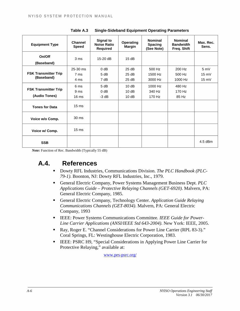
N Y I S O S Y S T E M P R O T E C T I O N M A N U A L
A-6 NYISO Operations Engineering Staff Version 3.1 06/30/2017
Table A.3 Single-Sideband Equipment Operating Parameters
Equipment Type Channel Speed
Signal to Noise Ratio
Required Operating
Margin Nominal Spacing
(See Note)
Nominal Bandwidth Freq. Shift
Max. Rec. Sens.
On/Off
(Baseband) 3 ms 15-20 dB 15 dB
FSK Transmitter Trip (Baseband)
25-30 ms 7 ms 4 ms
0 dB 5 dB 7 dB
25 dB 25 dB 25 dB
500 Hz 1500 Hz 3000 Hz
200 Hz 500 Hz 1000 Hz
5 mV 15 mV 15 mV
FSK Transmitter Trip
(Audio Tones)
6 ms 9 ms
16 ms
5 dB 0 dB -3 dB
10 dB 10 dB 10 dB
1000 Hz 340 Hz 170 Hz
480 Hz 170 Hz 85 Hz
Tones for Data 15 ms
Voice w/o Comp. 30 ms
Voice w/ Comp. 15 ms
SSB 4.5 dBm
Note: Function of Rec. Bandwidth (Typically 55 dB)
A.4. References Dowty RFL Industries, Communications Division. The PLC Handbook (PLC-
79-1). Boonton, NJ: Dowty RFL Industries, Inc., 1979. General Electric Company, Power Systems Management Business Dept. PLC
Applications Guide – Protective Relaying Channels (GET-6920). Malvern, PA: General Electric Company, 1985.
General Electric Company, Technology Center. Application Guide Relaying Communications Channels (GET-8034). Malvern, PA: General Electric Company, 1993
IEEE: Power Systems Communications Committee. IEEE Guide for Power-Line Carrier Applications (ANSI/IEEE Std 643-2004). New York: IEEE, 2005.
Ray, Roger E. “Channel Considerations for Power Line Carrier (RPL 83-3).” Coral Springs, FL: Westinghouse Electric Corporation, 1983.
IEEE: PSRC H9, “Special Considerations in Applying Power Line Carrier for Protective Relaying,” available at:
www.pes-psrc.org/

N Y I S O S Y S T E M P R O T E C T I O N M A N U A L
NYISO Operations Engineering Staff A-1 Version 3.1 06/30/2017
This page intentionally blank.

N Y I S O S Y S T E M P R O T E C T I O N M A N U A L
NYISO Operations Engineering Staff B-1 Version 3.1 06/30/2017
B.
Attachment B. Forms
B.1 Relay Characteristics Form
B.2 Clearing Times Form
B.3 Reclosing Data Form B.

N Y I S O S Y S T E M P R O T E C T I O N M A N U A L
B-2 NYISO Operations Engineering Staff Version 3.1 06/30/2017
B.1 Relay Characteristics Form
Line No.
Line Name
Terminal
Base Voltage
Submitted by Date
Protection System 1 Protection System 2
Type of Relay Scheme
CT Ratio
PT Ratio
Which Zone initiates Pilot Scheme?
Protection System 1 Protection System 2
Zone 1
Angle of Max Torque (Enter 0 for reactance relay)
Setting in Secondary Ohms
Offset in Secondary Ohms
Setting in Primary per unit (100 MVA base)
Protection System 1 Protection System 2
Zone 2
Angle of Max Torque (Enter 0 for reactance relay)
Setting in Secondary Ohms
Offset in Secondary Ohms
Setting in Primary per unit (100 MVA base)
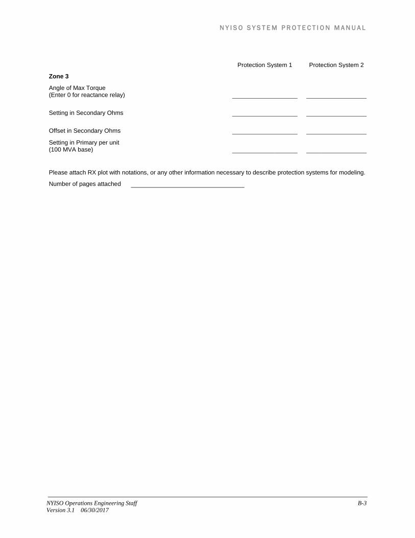
N Y I S O S Y S T E M P R O T E C T I O N M A N U A L
NYISO Operations Engineering Staff B-3 Version 3.1 06/30/2017
Protection System 1 Protection System 2
Zone 3
Angle of Max Torque (Enter 0 for reactance relay)
Setting in Secondary Ohms
Offset in Secondary Ohms
Setting in Primary per unit (100 MVA base)
Please attach RX plot with notations, or any other information necessary to describe protection systems for modeling.
Number of pages attached

N Y I S O S Y S T E M P R O T E C T I O N M A N U A L
B-4 NYISO Operations Engineering Staff Version 3.1 06/30/2017
B.2 Clearing Times Form
Line No.
Line Name
Terminal
Base Voltage
Submitted by Date
Clearing Times Viewed from the Terminal
Near End Fault (in cycles)
Far End Fault (in cycles)
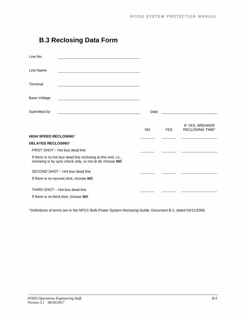
N Y I S O S Y S T E M P R O T E C T I O N M A N U A L
NYISO Operations Engineering Staff B-5 Version 3.1 06/30/2017
B.3 Reclosing Data Form
Line No.
Line Name
Terminal
Base Voltage
Submitted by Date
NO YES IF YES, BREAKER RECLOSING TIME*
HIGH SPEED RECLOSING*
DELAYED RECLOSING*
FIRST SHOT – Hot bus dead line
If there is no hot bus dead line reclosing at this end, i.e., reclosing is by sync check only, or not at all, choose NO.
SECOND SHOT – Hot bus dead line
If there is no second shot, choose NO.
THIRD SHOT – Hot bus dead line
If there is no third shot, choose NO.
* Definitions of terms are in the NPCC Bulk Power System Reclosing Guide, Document B-1, dated 03/11/2009.

N Y I S O S Y S T E M P R O T E C T I O N M A N U A L
B-6 NYISO Operations Engineering Staff Version 3.1 06/30/2017
This page intentionally blank.

N Y I S O S Y S T E M P R O T E C T I O N M A N U A L
NYISO Operations Engineering Staff C-1 Version 3.1 06/30/2017
C.
Attachment C Schedule for System Protection Data Collection
Table C.1 Schedule for System Protection Data Collection