system requirements specificationsuser.ceng.metu.edu.tr/~e1746221/docs/srs.pdf · system...
TRANSCRIPT
2013
Leş Koding Baran Küçükgüzel Batuhan Taşdöven Ali Barış Uzuner Bekir Öztürk
SYSTEM REQUIREMENTS SPECIFICATIONS This document is prepared by Leş Koding’s members; the document is about system requirements specifications about the project “Learning Prepositions”.

1
Contents 1. Introduction ............................................................................................................................ 3
1.1 Problem Definition .............................................................................................................. 3
1.2 Purpose .............................................................................................................................. 3
1.3 Scope ................................................................................................................................. 4
1.4 Definitions, acronyms, and abbreviations ................................................................................ 5
1.5 Overview ............................................................................................................................ 5
2. Overall description .................................................................................................................. 6
2.1 Product perspective .............................................................................................................. 6
2.1.1 System interfaces........................................................................................................... 7
2.1.1.1 Training Interface ....................................................................................................... 7
2.1.1.2 Configuration Identfier Interface ................................................................................... 8
2.1.2 User interfaces .............................................................................................................. 9
2.1.3 Hardware interfaces ....................................................................................................... 9
2.1.4 Site adaptation requirements ........................................................................................... 9
2.2 Product functions ................................................................................................................11
2.3 Constraints .........................................................................................................................13
2.4 Assumptions and dependencies ............................................................................................13
3. Specific requirements .............................................................................................................14
3.1 Interface Requirements ........................................................................................................14
3.2 Functional Requirements .....................................................................................................14
3.2.1 Registering Images and Configurations to Database ..........................................................15
3.3 Non-functional Requirements ...............................................................................................16
3.3.1 Performance requirements .............................................................................................16
3.3.2 Design constraints ........................................................................................................16
4 Data Model and Description ....................................................................................................17
4.1 Data Description .................................................................................................................17
4.1.1 Data objects .................................................................................................................17
4.1.2 Data dictionary .............................................................................................................19
5 Behavioral Model and Description ...........................................................................................19
5.1 Description for software behavior .........................................................................................19
5.2 State Transition Diagrams ....................................................................................................20
6 Planning .................................................................................................................................22

2
6.1 Team Structure ...................................................................................................................22
6.2 Estimation (Basic Schedule) ................................................................................................23
6.3 Process Model ....................................................................................................................24
7 Conclusion ..............................................................................................................................25
Figure 1...................................................................................................................................... 7
Figure 2...................................................................................................................................... 8
Figure 3.....................................................................................................................................10
Figure 4.....................................................................................................................................11
Figure 5.....................................................................................................................................12
Figure 6.....................................................................................................................................18
Figure 7.....................................................................................................................................20
Figure 8.....................................................................................................................................21
Figure 9.....................................................................................................................................21

3
1. Introduction
1.1 Problem Definition
Recently, Human-Robot Interaction has made great strides toward understanding and
improving our interactions with computer-based technologies. There has been recent studies on
increasing understanding of our behaviors for the robots because nowadays robots are designed
to meet the people needs. In order to designate robots that meet the people needs, robots should
be able to recognise differences between behaviors. In a sentence, prepositions can identify our
behaviors and by changing them, our behaviours can be changed slightly. Therefore, learning
prepositions for a robot could give it a chance to understand our behaviors better.
In this project, we are going to teach a robot basic prepositions(on, to, in and so on) by
using prototype-based conceptualization in a limited object set and expect him to learn general
prepositions concept.
1.2 Purpose
Software Requirement Specification document aims to specify the requirements for
Preposition Learning project and to give information about capabilities of the resulting
application and results of the research which will be done during implementation of the project.
This software requirements specification document addresses the ones who are going to develop
this system, Cognitive Vision Lab in University of Southern Denmark, KOVAN in Middle East
Technical University and the instructors who are responsible for this graduation projects.
This document will explain the scenario of the desired project and necessary steps in
order to achieve the tasks such as the definition of the problem that this projects presents a
solution, definitions and abbreviations that are relevant to the project.
It will also explain how to establish the basis for agreement between the developers and
the suppliers on what is done in this project. The complete description of the functions that are
performed by the software will assist to determine if the software meets their needs.
The preparation of this SRS will specify all the requirements before design begins, during
re-designing, coding, and testing.
4
1.3 Scope
The project that is specified in this document and are going to implement is namely
Preposition Learning Project. This project will be done in order to make a research on the topic
of machine learning and to make contribution to literature. This application is planned to reveal
importance of preposition concept and make contribution to future researches which are related
to topic of teaching linguistic concepts to robots.
In this project, we will have two main parts which are teaching categories and repositions
to robot and inferencing of prepositions in terms of given image. The promised functionalities of
the application will be implemented by means of object recognition, object tracking, extracting
object features and categorizing them. By the application, the real world scene which consists of
basically a table and objects on top of it is captured. By the information obtained from the
sensors which may be cameras and touch sensors, features of the scene will be extracted and will
be stored in a database in order to make correct assumptions in future. In this part, in order to
store data in a meaningful way, we are going to use prototype-based conceptualization. In this
way, we are going to decide on features of the prepositions such as width of objects, height of
objects, orientation of objects, contact points and so on. By using these features, we are going to
infer a prototype so that it includes features relations. For instance, if we work on “far”
preposition, orientations of the objects should not be close to each other so we can mark this
features as “big”. However, width and height of the objects do not give any related information
for “far” preposition. Thus, we can mark them as irrelevant. Similarly, there should not be any
contact point between two objects if they are far away from each other. Therefore, we can mark
contact point feature as “zero”. By using these kind of prototypes, we will try to teach robot
prepositions.
After the training part of the project, robot will be able to understand relation between
objects and by using these relations, it will be able to infer relations between objects provided in
a new scene.

5
1.4 Definitions, acronyms, and abbreviations
Nao An autonomous, programmable humanoid robot
DB Database
IEEE Institute of Electrical and Electronics Engineering
UML Unified Modelling Language
SRS Software Requirements Specification
IDE Integrated Development Environment
ER Entity - Relationship Diagram
GUI Graphical User Interface
1.5 Overview
This document contains a detailed description about the project Preposition Learning. In
the introduction part of this document, it mostly gives a general overview about the project
including the definition of a real world problem that project intends to solve and the scope of this
project. Also in this part, the purpose of the SRS and the scope of the project are clearly
explained. Second part of the document is the overall description of the project. In this part, the
perspectives of the application, the functions included in the application and the constraints,
assumptions and dependencies of the desired application are explained. The specific
requirements of the project are identified in the next part of the document. This part includes
interface, functional and nonfunctional requirements of the project. In the fourth part, data
models and their descriptions are explained in detailed way with the relationships between them.
The behavioral model and its descriptions are lastly included in the fifth part.. In the seventh
part, team structure and introduction of the team members of the project are explained. The final
part is conclusion part. A brief summary of the whole document will be given in that part.

6
2. Overall description
This section will give information about product perspective, product functions,
constraints, assumptions and dependencies.
2.1 Product perspective
Our project is going to provide two facilities. The first facility which we aim to do is
training the robot. We are going to train the robot by providing images. The images is going to
be related with some the propositions. After perceiving the input, the training system will register
these datas to the training database. Second facility which the system is going to be capable of is
relating current configuration with the training database, hence deciding verbal form (the
preposition) of the configuration.

7
2.1.1 System interfaces
2.1.1.1 Training Interface
Figure 1
The training interface is used to register data to the training database. The training
interface has two inputs, one of them is the an image of the current configuration, the second
input is the preposition which defines the current configuration best. The interface is going to
extract information from the image provided. After extracting the information from the image,
the system is going to relate the information with the preposition provided. The preposition is
going to be prototyped with some features. The similar properties of an image, for a preposition
is going to be the deciding factor for that preposition. The system is going to find the similar
properties of the same configurations labeled with same prepositions. These similar features of a
configuration is going to be used for deciding the label of another configuration in later use. The
extracted information will be saved to the training data database.

8
2.1.1.2 Configuration Identfier Interface
Figure 2
The Configuration Identifier interface is going to be used for deciding the current
configuration of the system in a verbal form. The image is going to be given as an input similar
to the Training Interface. However this time the system is not going to have the verbal
information related with the current configuration of the objects. This part of the system will take
the image as input and will extract information from the image by processing the image. After
having the related features , the system is going to compare current features of the configuration
with the learned features of the configuration before. When the comparing process is done , the
system will decide the current configuration of the system, then the speech module of the system
is going to be active. The speech module is going to tell the current configuration of the system
verbally.

9
2.1.2 User interfaces
The system is not going to interact with humans directly when working. However the
system will provide an user interface for training. The user will be able to register an image of
current configuration and a preposition which explains the current configuration of the objects.
2.1.3 Hardware interfaces
The system is planned to work on the Nao robot. The nao robot is provided by Sinan
Kalkan from Kovan Research Lab.The software is going to run on nao. Nao is going to take
images and the images are going to be provided as input to the software, then the software is
going to decide the form of configuration. The speech module will work with Nao, the decided
result is going to be voiced out from Nao.
2.1.4 Site adaptation requirements
The configurations which the system is going to identify should be explained with the
prepositions below:
● “in”
● “on”
● “under”
● “over”
● “behind”
● “between”
● “out”
● “far”
● “near”
● “into”

10
Figure 3
We are going to expect from robot to identify prepositions on the platform between group
of objects which are listed below:
● box
● cylinder
● cup
● ball
● cube

11
2.2 Product functions
Figure 4
● The user should be able to register a new image together with the preposition defining the
related configuration to the training database.
● The features of an configuration will be represented as vectors in the system like
[ f1,f2,……. , fn].

12
● There will be some irrelevant features for each configuration, the irrelevant features will
be labeled as “*” for a configuration, when storing the related features vector for the
related configuration.
● The images will processed and the features vector will obtained from the processed info.
● The user should be able to decide the defining features of a configuration.
● The user should be able to decide the irrelevant features of a configuration.
● The user is able to delete an registered image along with related information from the
training data database.
● The user is able to see the defining features of a configuration.
● The user is able to see the irrelevant features of a configuration.
The actor in the above situations is the user who registers data to the training data database.
Figure 5
13
● The image of current configuration should be captured and provided to the software from
the working environment.
● The image should be converted to a features vector of [ f1,f2,……. , fn] by processing the
image.
● The extracted information from the image is going to be compared with the registered
information with the database, hence the most suitable preposition to explain the
configuration will be decided.
● The string representation of the current configuration between objects will be computed.
● The system is going to stream the verbal form of the current configuration.
The actor in the above situations is the identification module of the software.
2.3 Constraints
Since image processing process is highly affected by the quality of the images from the
camera, operations may not give the expected results under low or too high light.
On the other hand, project aims robot to have a better understanding of prepositions and
the reliability of the results is not guaranteed.
It is also required that there are no more than 2 objects on the images. In other words,
having more than 2 objects on the same image may cause unexpected results in the output or no
result at all. Similarly, if one of the objects is mostly hidden behind the other object, it will not be
possible to decide on prepositions since the other object is not clearly visible.
As it is a fact of vision, the robot should not be far away from the platform more than 3
meters and whole platform should completely be seen by the camera of the robot.
In the images that will be given as input, there should not be any conflict situation such as
having more than one preposition on them.
2.4 Assumptions and dependencies
It is assumed that all the images that are used in the calculations will have only 2 objects
on them. It is not possible to decide on prepositions if the scene contains more than 2 objects or
14
contains no objects at all. It is also assumed that the objects on the images will have colors
different than the color of the floor and they will be enlightened enough.
In this project, we are going to use Nao robot which autonomous, programmable
humanoid robot. Therefore, in every step we take, we will depend on Nao robot. The Nao robot
will make us comfortable while developing the project; however, if we go beyond and extend the
project for future extensions, capabilities of Nao will choke the life out of our ways. For this
reason, we will be fully aware of this and always try to make our research and development
independent of Nao, as possible as it can be.
3. Specific requirements
Requirements can be divided into 3 parts as Interface Requirements, Functional
Requirements and Non-Functional Requirements.
3.1 Interface Requirements
Since we are using Nao Robot in our application, all interactions with the system will be
done via sensors on Nao.
When user touches the touch sensors on its head, Nao will capture the image of the scene
in front of it using the camera.
After the calculations, user will be informed about the output via speakers on Nao. In this
case the output will be given in an English sentence.
No other images will be captured until another touch input arrives at Nao.
3.2 Functional Requirements
This subsection is a description of each major software function, along with data flow
and requirements of the function.

15
3.2.1 Registering Images and Configurations to Database
When an image arrives, a configuration data will be created immediately. Software is
expected to register images and the configurations to database for later use.
3.2.2 Decide the Defining Features of a Configuration
After registering many images to database as the training data for a preposition, software
is expected to define an array of features that is to be used during the decision phase.
3.2.3 Decide the Irrelevant Features of a Configuration
After registering many images to database as the training data for a preposition, software
is expected to get rid of irrelevant features so that those features will not be used during the
recognition of this preposition.
3.2.4 Delete the Image and the Related Information from the Database
In case that an image is found irrelevant or no longer appropriate for the training data of
that preposition, it should be possible to remove the image and all the corresponding data from
the database.
3.2.5 See the Deciding Features of a Configuration
The software should be able to show the deciding futures of a certain configuration if
necessary.
3.2.6 See the Irrelevant Features of a Configuration
The software should be able to show the irrelevant features of a certain configuration if
necessary.
3.2.6 Capturing an Image for the Decision Phase
The software is expected to capture the images using the camera when commanded.

16
3.2.7 Perceiving Current Image and Creating Its Features Vector
The software is expected to create the features vector using the image captured
previously. This futures vector will contain all the data necessary for a configuration comparison.
3.2.8 Matching the Calculated Configuration With a Configuration from the
Database
Using the configurations fetched from the database, the software is expected to find the
best match for the configuration that is created using the latest image captured. If it finds a
match, this will lead us to the preposition that is assigned to that configuration.
3.3 Non-functional Requirements
3.3.1 Performance requirements
● There will be only one user who can register data to the software at the same time.
● There will be only one user who decide the deciding or the irrelevant features of data at
the same time.
● The user will be able to register new data or delete the existing data from the database in
at most 1 seconds.
● The user will be able to register multiple number of images for a related configuration.
● The software should recognize the configuration less than 3 second since the
configuration is an based on real-time.
● The software is going to run on a robotic environment, hence the capturing devices of the
robotic environment should be able to take the picture of the scene in less than 1 seconds.
● The software should process the data and compute features of the configuration less than
1 seconds.
● The software should be able to recognize the two objects thats in the scene.
● The software should give the output in a format that humans can hear and understand.
3.3.2 Design constraints
● The system shall run on a robotic environment with a camera and a sound system.
17
● The system will not have any security problems since the software will run on a single
system.
● The system should be portable to different robotic environments. ( NAO and other
robotic environments)
● The project will be coded using C++ and python.
4 Data Model and Description
This section describes information domain for the software.
4.1 Data Description
Data objects that will be managed/manipulated by the software are described in this
section.
4.1.1 Data objects
Sets of 2D images will be used as data. These images will be under couple of specialities.
These are examples like images including “on” preposition, images including “under”
preposition etc.

18
Figure 6
The problem on here is, size of images is too big and we don’t need the all pixel
informations on our experiment. Because of that, we have some features from images. And
saving this feature vector is more advantageous than keeping all the images considering storage
area.
Features are some special properties which we are trying to categorize images. For
example if all the images in “on” directory have similar values in same feature, we will save it.
And in our algorithm we will expect the similar values in that feature, before say “in this image,
one object is on another object”.
19
4.1.2 Data dictionary
Preposition: To position or place in position in advance.
Feature: A speciality from image which we are trying to categorize.
Some of these features are;
Width: Width of the objects.
Height: Height of the objects.
Contact Point x,y,z: The information about is there any contact point on that axis.
Orientation: Position and rotation informations of objects.
5 Behavioral Model and Description
This section presents a description of the behavior of the software.
5.1 Description for software behavior
Software will be given sets of images describing each preposition. For example, there will be a
set of images provided for “in” another set for “on”, “near” and so on. Each of these sets will be used as a
reference during the decision phase. Decision phase is the phase where software decides which
preposition explains the positions of the objects on the image the best.
20
5.2 State Transition Diagrams
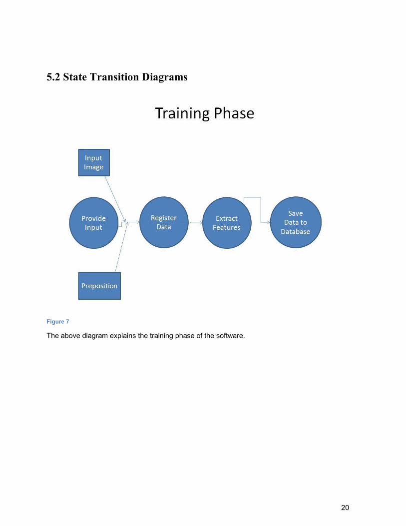
Figure 7
The above diagram explains the training phase of the software.
21
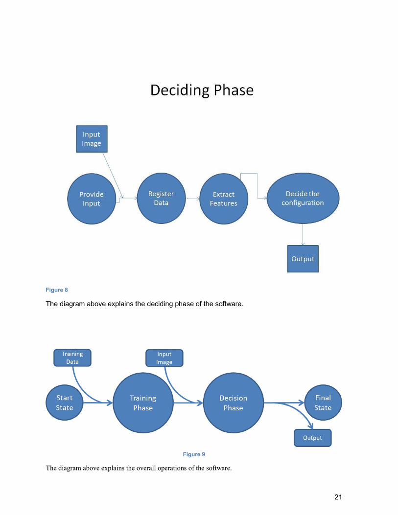
Figure 8
The diagram above explains the deciding phase of the software.
Figure 9
The diagram above explains the overall operations of the software.

22
6 Planning
In this part of the document, the structure of the team responsible from the
project, the basic schedule, and the process model will be presented.
6.1 Team Structure
Our team consists of Ali Barış Uzuner, Baran Küçükgüzel, Batuhan Taşdöven and Bekir
Öztürk. Those have worked on same projects for a long time and have enough experience on
work sharing. In our team, there will not be any project leader. Therefore, we will be deciding on
important issues all together. In each step of the progress, the new tasks will be accomplished by
whom it is assigned to. These assignments will be planned to divide the workload equally. We
will have weekly meetings with our assistant Serdar Çiftçi. We will also have regular meetings
with our consultant teachers who are Asst. Prof.Sinan Kalkan and Prof. Norbert Krüger to take
some advice and to decide next steps of the project.

23
6.2 Estimation (Basic Schedule)

24
6.3 Process Model
After examining the process models, our team decided to go on The Waterfall Model. it
is sometimes called as The Classic Life Cycle. it is a sequential design process, in which
progress is seen as flowing steadily downwards (like a waterfall) through the phases of
Conception, Initiation, Analysis, Design, Construction, Testing, Production/Implementation, and
Maintenance.
At each phase of the Waterfall Model, required documentation will be done by our team.
The document for the first phase, requirement phase, is this document.

25
7 Conclusion
This document gives informatin about the project “Learning Prepositions” which aims to
teach robots prepositions by using protype-based conceptualization method suggested by Sinan
Kalkan. First of all the aim of the project is described, then our solution aproach to this problem
is explanied in the document. To explaing this we have tried to explain basic functionality of the
project, interface requirements of the application, performance, attributes, and design constraints
imposed on the implementation. In the overall description part, all of the functions that this
application is going to be able to do explanied. User and function relationships, user roles and
characteristics are modeled. The assumptions that will maintain the accuracy are made in order
to sustain a reliable application, in addition to that data models and behavioral models are
presented. Finally we presented the team structure and basic expected schedule and the process
model for the team “Leş Koding”.