itbaba.comitbaba.com/ditnotes/operating systems.doc · web viewmultiprocessor scheduling usually,...
TRANSCRIPT

OPERATING SYSTEMS
1. Basic Elements of a Computer
Processor: This is the heart of the computer, consisting of an arithmetic and logic unit (ALU), registers, and various other hardware elements.
Main Memory: This is where the running programs and their data reside. The processor directly interacts with the main memory by reading from and writing on it.
System Bus: This is the interface that connects the various elements of a computer together.
2. Processor Registers
User-visible registers: Registers that are accessible by users generally contain data, addresses, pointers to memory locations, etc. Data registers are referred to as accumulators while those that contain addresses are the stack pointers, memory segment base pointer, and the like.
Control and Status registers: These registers are not visible by users. Only the operating system can gain access to them. They are made up of a program counter (PC), instruction register (IR), program status word (PSW) and many others.
3. Instruction Execution
The execution of program instructions by the processor follows a cycle. The most basic cycle is the following:
Fetch next instruction from main memory using the Program Counter register (PC) and place it in the Instruction Register (IR)
Increment the PC register Execute instruction in IR Verify interrupt lines go to beginning
There are four different types of instructions: Processor-memory: These instructions perform the data transfers from the
memory towards the CPU registers and back. They read like LOAD A6, WRITE 0x56de2, etc.
Processor-I/O: These instructions perform the transfers from the CPU towards I/O controllers and back.
Data processing: These instructions perform arithmetic and logic operations on the contents of registers.
Compiled by http:www.itbaba.com 1

Control: These instructions control the flow of execution of a program. They may specify to what address the PC must jump, and they are used in the implementation of loop and conditional statement structures.
4. I/O Functions
Traditionally, I/O controllers would exchange data directly with the CPU. This, however, is a bit inefficient and other techniques have been developed. For instance, modern I/O controllers now perform data exchanges directly to and from memory, preventing the CPU to be in an active waiting loop. This technique is called DMA (Direct Memory Access) and is implemented with a dedicated processor for this type of data transport.
5. Interrupts
The purpose of having interrupts is to stop the CPU's current executing of a task (process) to attend a more pressing event right away. In modern computers, interrupts are essential. Without them, there is a number of Operating System Concepts we would not be able to implement. There are different events in a computer that will trigger an interruption and that is why we may speak of classes of interrupts and types of interrupts. Here is a short and incomplete list of events giving rise to interruptions of the CPU:
Program: Generated by an instruction that cannot be completed Timer: Scheduled interrupts, required for process management I/O: I/O controller to signal completion of a data transfer Hardware failure: Component unable to satisfy requests
The internals of the interrupts mechanism can be a little tricky. Here's a simplified example of how an interrupt may be generated and then serviced:
A device raises the processor interrupt line, and dumps the memory address of the interrupt handling code on the address bus for the processor
The processor saves all its register values on the current stack (a special purpose location in memory)
The processor attends to the interruption by executing code that is located at the address provided by the device (on the address bus)
When the interrupt handling code returns, it does it in the scheduler, which resets the CPU registers to the values they contained just before the interruption, including the PC, therefore resuming the execution of the process that was interrupted.
Now, an interesting question is: Since interrupts can happen at any time, how do we deal with interruptions that occur when the processor is already servicing a first interruption? There are two ways of answering this question:
We may, when servicing an interrupt, disable the processor's capability for being interrupted until it completes the first interruption. Any device that would raise the INT line would then have to wait for the CPU to be coming back from being interrupted for this new interruption to get serviced.
Compiled by http:www.itbaba.com 2

Another way of dealing with the problem is to prioritize interruptions. This allows a CPU servicing an interruption to be interrupted if the new interruption has a higher priority than the one currently serviced.
The second method is better for systems in which interruptions must be serviced right away. If that is not the case, then the first solution is simpler to implement in hardware and in software.
6. Multiprogramming
The idea of multiprogramming is to allow many users to use a single computer simultaneously. This can be achieved with the implementation of concepts such as processes, virtual memory management, and the like. Interrupts are absolutely necessary to the adequate implementation of multiprogramming.
7. The Memory Hierarchy
The need to store large amounts of data permanently and also the need to store programs and data in the main memory of computers lead to the development of many types of memories. For instance, devices that allow to store large quantities of data are typically slow to access. On the other hand, cache memory and RAM contain much less data but can be accessed very rapidly. All of this lead to an understanding of the different types of memories that is hierarchical. Let's have a look at this concept:
Inboard memory: Registers, Cache, Main Memory Outboard memory: Hard Disk, CD-ROM, CD-RW, DVD Off-line: Magnetic tapes, etc.
We can see that at the top of this scale we have very fast yet very small memories. At the bottom we find memories that can store enormous amounts of data but that are very slow in terms of transfer rates.
© Dr S. S. Beauchemin, All Rights ReservedLast update 15/01/02
CS305b OPERATING SYSTEMS
Compiled by http:www.itbaba.com 3

1. Cache Memory
Cache memory is transparent, even to the operating system. It is a hardware trick to speed up the instruction cycle. As we know, each time the processor executes an instruction, it must complete an execution cycle that includes fetching the next instruction in main memory. This fetch operation has an overhead, and each time an instruction is to be fetched, we must pay this price. Note that this is the same with user program data. This problem exists each time the processor wants to load something from main memory, whether this is data, address, or code.
Hence, instead of having to deal with this overhead for every memory location to be loaded in the CPU, we provide computers with a small, very fast memory that lies right between the CPU and the main memory, in fact adding another level to the memory hierarchy.
The role of this cache is to contain a portion of the main memory contents. Since, most times, when the processor loads a memory location, the next one to be loaded will be near that first one (principle of locality), it makes sense for the cache to contain a continuous part of the main memory. So, when the CPU wants to load the contents of a memory location, if it is present in cache, it doesn't have to make an access to main memory; it simply needs to load from cache, and that is a lot faster. If the memory location is not in cache, then another block is loaded in cache, the one containing the referenced memory cache. In this way, we afford the RAM access overhead once per block of locations, rather than each time a memory location has to be loaded.
Of course, this is fine for reading from main memory through a cache memory. How about writing in it? The added difficulty here is that if the memory location is in cache, then this is where the CPU will write. But this cache location corresponds to a memory location in RAM, and that one is not getting written, bringing an inconsistency of the worst kind. So, a cache block that has been written on is said to be dirty, and needs to be written back into main memory at some point, that point being when the block has to be replaced by another in cache.
We can see that the elements required to implement a cache memory for a computer, aside from cache size and block size issues are:
Mapping function, to map memory blocks to the cache blocks Replacement strategy, to decide what block to replace when loading a new block
in cache Write policy, to make sure dirty block do not create inconsistencies
2. Cache Memory Design
Compiled by http:www.itbaba.com 4

We can describe the size of main memory as a power of two: 2^n, where n is the number of bytes required to address any location in memory. We can also describe the memory as a bunch of blocks (containing more than one memory location) containing K memory locations. Thus the main memory is made up of 2^n/K blocks. The cache consists of C slots of K memory locations, where C << 2^n/K. If the block size is also a power of two, then K = 2^m with m < n, and the number of blocks in main memory is 2^(n-m). The number of bits required to uniquely identify a block is n-m. So, taking the n-m higher-order bits of a memory address, gives us the memory location of the block containing the address. The rest of the bits are the offset within that block. The high-order bits are called a tag and it is with these bits that the mapping function works. The cache contains a tag field for every block that makes it up and to verify if a block is in cache, the hardware looks in the tag fields to find the n-m bits that identify it. If found, the block is in cache and, if not, it is simply not in cache.
Let us have a look at the internals of the hardware that implements cache memory. Suppose the CPU wants to read a memory location from memory. The following suite of actions will happen:
receive address A from CPU take n-m higher-order bits from A and try to match it with one of the tag fields of
the cache memory If tag found (block in cache) then
o access main memory for block containing A o allocate cache slot for main memory block o deliver contents of address A to CPU o load main memory block in cache
else o get contents of address A from the cache block o deliver it to the CPU
end
3. I/O Communication Techniques
There exists three different ways of performing I/O communications. In historical order, they are programmed I/O, interrupt-driven I/O, and Direct Memory Access (DMA).
3.1 Programmed I/O
Programmed I/O means that the processor needs to wait on an I/O controller to get what it is asking for. The name comes from the fact that the CPU enters a loop to pool on the status of the controller. Here is what happens for programmed I/O:
issue READ command to I/O controller while I/O status not ready do wait read data from I/O module write data in memory
Compiled by http:www.itbaba.com 5

3.2 Interrupt-Driven I/O
Instead of having the CPU wait on the results of an I/O operation through a controller, why not send it do something more useful? The idea behind this is to have the processor issue the I/O command to the controller but then it calls the scheduler immediately thereafter to give control to another process. Only an interrupt, coming from the controller to signify that it is done with the I/O, will bring the execution of the prior process to collect the results of its I/O operation. In this way, we do not make the processor waste its time in an active loop. Here is a typical sequence of events:
issue READ command to I/O controller CPU is interrupted and goes to work on another process I/O controller raises INT line to signal it is done CPU comes back to process that issued I/O command CPU reads data from I/O controller CPU writes data in main memory
3.3 Direct Memory Access (DMA)
Still, in interrupt-driven I/O, the CPU is still involved. In particular for transferring the data from the controller to the memory. Are there ways to avoid this? One may want to consider that an I/O controller itself could do that when ready. In fact, that is exactly what DMA is about. Here is what typically happens in DMA I/O:
issue READ command to I/O controller CPU is interrupted and goes to work on another process controller does its job until done controller transfers its data to main memory I/O controller raises INT line to signal it is done CPU reads controller status to see if operation is successful
As can be seen, not once is the CPU transferring data to the main memory from the controller, hence freeing it almost completely from the burden of doing I/O, which is typically slow.
CS305b OPERATING SYSTEMS
Compiled by http:www.itbaba.com 6

1. The OS as a User Interface
The computer provides applications to users in a layered structure where, directly interacting with the hardware, we find the Operating System:
Application programs Utilities Operating System Computer Hardware
The types of services are: Program development Program execution Access to I/O devices Access to files Access to system Error detection
2. The OS as a Resource Manager
The OS typically manages all the movement, storage and processing of information, stored as data. The OS works like any other program on the computer. That is, it is not running when a user program runs, it has to relinquish the CPU, etc. So in fact, the OS leaves control when other programs are run. Only hardware events bring it back, such as interruptions.
3. Evolving an Operating System
The ease with which an OS can evolve is really crucial. There is new hardware appearing on a constant basis. There are new services to be provided and there are the proverbial fixes and patches to resolve OS bugs. The quality of an OS also resides in its capability for evolution.
4. The Evolution of Operating Systems
Simple Batch Systems: The central idea here is to have a program called a monitor to take jobs sequentially, one after the other. The memory layout of such simple systems would look like:
o Interrupt processing o Device drivers o Job sequencing o Control language interpreter o User area
Each job is controlled by a JCL (Job Control Language) supported by the monitor for the use of the operator. The first batch system was developed by General Motors in 1955, on an IBM machine.
Compiled by http:www.itbaba.com 7

Multiprogrammed Batch Systems: To have an idle CPU during the sixties was a really bad idea, because of the operational costs. The goal was to make an efficient use of time. For instance, not to have the CPU do active waits on I/O operations, etc.
It is known that I/O is still the bottleneck of computational devices. To avoid a large part of this overhead, OS designers decided to have more than one job resident on the computer. When a job would do an I/O with the CPU waiting for the result, the other job would start executing and the fist job would return only when with its I/O completed. In this way, active waits were eliminated. This is how the concept of multiprogramming appeared.
Memory Management: The implementation of multiprogramming lead to different problems such as memory space for jobs and so on. With more than one job in memory, questions arose:
o Illegal memory accesses? o Shared memory? o Memory space?
Time-Sharing Systems: The implementation of multiprogramming lead to different problems Direct interaction with the computer was also needed, for jobs with interactive interfaces such as data entry, transaction processing, etc. This lead to the concept of time sharing and systems evolved to handle such jobs. The first system with time sharing concepts was implemented at M.I.T. in 1961.
At this point in time, many challenges has to be overcome, including protecting jobs from each other, sharing a unique file-system, competing for system resources, etc.
5. Processes
There were many definitions of what a process is over the years let us have a look at them in chronological order:
A running program An instance of a running program An entity assignable to a CPU A unit of activity defined by a single thread of execution and state.
The components of a process are: An executable set of instructions Its associated data The execution context
6. Memory Management
With processes, memory management becomes more complicated. The OS must isolate processes from each other, but still must allow them to communicate. There are
Compiled by http:www.itbaba.com 8

automatic memory allocation and management issues, shared memory mechanisms, long term storage and so on.
These requirements are met with two fundamental elements of an OS: A virtual memory and an adequate file system. Virtual memory is nothing more than providing the users with an address space that is larger than the physical addressing space of a computer. This is possible by realizing that, for a program to run, all of its elements do not have to be stored in main memory at any one time.
In a virtual addressing space, we speak of virtual addresses whereas in main memory, we speak of physical addresses. A virtual address is made up of a page number (in a a paged memory system) plus an offset within that page. A physical address is made of a page location in main memory plus the offset within that page location.
The principles of a paged virtual memory system are
All the pages of a process on disk are continuous. When a program starts (becomes a process) the minimum number of pages
required for its execution are loaded in memory, wherever there is room. In addition, the pages do not require to be stored sequentially. They can be anywhere.
There is a page table, managed by to OS, which tells where every loaded virtual memory page is located in main memory. This table is used in the address resolution process.
A paged memory system is at the core of virtual memory systems. The hardware must be designed (CPU and memory) so that is supports paged
memory blocks. That is, we need more than just the OS software to implement a virtual memory system.
7. Scheduling and Resource Management
Active processes need to be managed fairly. For this to happen, the OS scheduler needs to implement a equitable policy for resource sharing (CPU, devices, etc.). However, it is not always clear what is fair in terms of scheduling. Here are a few contradictory goals:
Maximization of throughput Minimization of response time Accommodate as many users as possible
There are different techniques for the scheduling of processes: Round-robin Dynamic priority levels (UNIX) Hybrid
The scheduling parameters can also be modified by systems administrators to fine tune performance given the type of process loads that are most often encountered.
Compiled by http:www.itbaba.com 9

8. Operating System Structure
Operating Systems are really big pieces of software. To construct them with a minimum number of after-delivery bugs, it is required to resort to more powerful design paradigms than just structured programming. We design Operating Systems with layers. It is a little bit like an onion, where a given layer's services are implemented with the services of the inner layers only. Here is an example of such layers:
1. Shell 2. Process 3. Directories 4. Devices 5. File system 6. Communication 7. Virtual memory 8. Local secondary storage 9. Primitive processes 10. Interrupts 11. Hardware
This is the implementation strategy of most modern Operating Systems.
9. Characteristics of Modern Operating Systems
Other useful concepts have been put forward and implemented in OS. These are: Micro-kernels: They contain just a few essential functions. Other OS services are
implemented by processes (the daemons of UNIX, for instance). Multi-threading: Processes as a collection of one or more threads and associated
resources. A thread is a unit of work, including processor context, private data and stack.
Symmetric Multi-Processing (SMP): Operating Systems that are capable of distributing their process loads onto many processors.
Distributed Operating Systems: Operating Systems that are capable of running over a network, rather than a single computer.
OO Design of OS:New ideas being brought to OS construction to minimize bugs and errors.
These concepts and their implementation will be explored as they represent the state-of-the-art in OS design, implementation and maintenance.
Compiled by http:www.itbaba.com 10

CS305b OPERATING SYSTEMS
1. Process Description and Control
Modern operating systems must satisfy the requirement to interleave the execution of multiple processes, to allocate resources to processes and to provide them with interprocess communication means. To do this, an operating system needs to manage most aspects of processes and such concepts as process states and process operations need to be defined.
Compiled by http:www.itbaba.com 11

2. Process States
A process state describes the current situation of a process. For example, a process in a READY state is capable of running but it is not and, a process in the RUNNING state is the process owning the CPU for its execution. So the simplest model for process states is a 2-state model including RUNNING and NOT-RUNNING. This model includes a queue for the processes in the NOT-RUNNING state, because there may be more than one process in this state. The RUNNING state does not require such a queue because there can only be one process running on a mono-processor machine.
Operations that can be applied to the RUNNING process is a PAUSE action that will transfer it from the RUNNING state into the NOT-RUNNING state and move its data structures (or pointers to) into the NOT-RUNNING queue. This action must be accompanied by a DISPATCH, which chooses a process from the queue and gives it the processor.
3. Process Creation and Termination
How do processes get created? There are many ways, each involving the operating system at some level. Here's a list of the various reasons for creating a process:
OS-created: to provide a service (the daemons in UNIX are a prime example of this)
Interactive login: a user enters the system (a shell in UNIX) Created by an existing process: to support parallelism or concurrency Batch job given for execution: this is the & after a command line in UNIX
Of course, all processes that are created must at some point be terminated. The reasons for terminating a process are many:
Normal completion of process Time limit reached (if such limit imposed) Illegal memory access Arithmetic error Attempted access to denied resources Parent process termination Sys. Admin. intervention etc.
It is easy to see that the creation and termination of processes are essential operations an OS must provide. As well, every aspect of a process is involved in its creation and termination. They are elaborate OS services.
4. A More Realistic Process State Model
There are many reasons for which a process may be in the NOT-RUNNING queue and the OS needs to know this. So it is natural to consider other process states that are more descriptive of the reasons for which they are not being run. These states could be:
Compiled by http:www.itbaba.com 12

Running: Only one process is in that state. It possesses the CPU. Ready: These processes are ready to be run and are waiting for the OS to give
them the CPU. Blocked: These processes cannot be run until some event occurs, such as the
completion of an I/O operation. New: Process just created and not yet admissible to the ready queue. Exit: Process taken out of the system for some reason.
There are operations to change the state of processes. Not every combination of state to state changes is permitted. For example, a process in the new state can't directly go to the running state. Here's a list of the admissible operations that assure state transitions:
Admit (new to ready): When the operating system is finished creating the data structures and allocating and the memory for the process, then it changes its state to ready.
Dispatch (ready to running): The OS chooses a process from the ready queue to run. The current process is put back in the ready queue.
Time-out (running to ready): A timer interruption signals that the running process must leave the CPU. The OS puts it back in the ready queue.
Event wait (running to blocked): A process requested something for which it must wait. Hence, the OS does not leave it on the processor where it would do an active wait, it is put in the blocked queue and another ready process is given the CPU.
Event occurrence (blocked to ready): The event for which the process was waiting occurs and it is put back in the ready queue.
Release (running to exit): The process has terminated for some reason and the OS gets rid of it.
5. Process Description
In order to perform adequate process management, the OS must be in a position to keep information about them. Exactly what information it needs to keep can be determined by looking at the data structures that are related to process management in any OS for which the source code is available.
Memory tables are kept by the OS to keep track of memory usage (main and secondary storage such as disks). The information they include is constituted of the following elements:
Allocation of main memory to processes Allocation of disk space to processes Protection attributes of that memory Other elements required by virtual memory systems.
I/O tables are also part of the OS so that they can be attributed to processes.
Compiled by http:www.itbaba.com 13

File tables are required for many purposes other than process management, yet the OS must know at any moment what process has what file in what mode.
Process tables are kept so that the OS can access the information about existing processes. There are many tables and data structures that are related to processes and we will examine them.
5.1. Process Control Structures
The physical reality of a process determines its attributes and it is used in deciding what information is required by the OS. The physical elements are:
Code Data locations (local and global variables, constants, etc) A process stack (keeping track of procedure calls and parameter passing) A process control block (containing process attributes)
These elements are called the process image and is kept in memory (If memory is paged, then the image of a process can be scattered all around the RAM in a non-contiguous fashion). Sometimes, a process image may be swapped to disk for various reasons. We will examine this possibility later.
The information about processes required by an OS is given in the following list, and can be thought of as a Process Control Block (PCB):
Process Identification o Process id (unique) o Parent process id o User id
Processor State Information (process context) o Processor registers o Stack pointers
Process Control Information o Process state o Priority o Scheduling information o Event information
Pointers to Other PCBs Interprocess Communication
o Semaphores o Sockets
Process Privileges Memory Management (pointers to process image) Resource Ownership
5.2. Process Control Block
Compiled by http:www.itbaba.com 14

The PCB is a fundamental data structure in an OS. The PCBs really describe the state in which an OS is. The queues that are associated with the various process states are linked lists of PCBs. The only state without a queue is the running state, and the running process is identified by the OS by a pointer to its PCB in the ready queue.
CS305b OPERATING SYSTEMS
1. The Role of the Process Control Block (PCB)
The PCB is the most fundamental data structure in an OS, since almost all OS modules access it. This means that a change in the PCB structure involves a major rewrite of several OS modules. What is in a PCB? A lot of stuff actually. We, however, can group them into logical sets. So the whole thing for a process is a PCB and the process image in main memory:
Process Control Block o Process ID o Processor state (context) o Process control information
Process Image
Compiled by http:www.itbaba.com 15

o User stack o Private user space o Shared user space
PCBs can be found in more than one data structure within an OS. In general, for each process state, we have a queue of PCBs. This is a clean way of organizing things since the queue in which a PCB is found describe its state immediately.
2. Process Control
There are two modes of execution for processes, in modern OS. There are very good reasons for this. Among them, we find the need to protect the integrity of the OS and its data structures from errors or malice coming from user processes.
The modes of execution differ in many ways. The most important one is that the less privileged mode, usually referred to as the user mode only has access to a restricted subset of the CPU's instruction set. The type of instructions denied to users processes are those that deal with the programming of certain interfaces, instructions that enable and disable interruptions, and the like.
The more privileged modes (there might be more than one) have a greater access to the CPU, and hardware devices. These modes are usually reserved for the processes and the kernel of the OS.
The switch between these modes requires some hardware support. It cannot be accomplished only by software. The mode of execution can be read from the PSW (Process Status Word register). Now the trick is to go from user mode to kernel mode without having a user process doing it. Events such as interrupts and system calls (from user processes) are required to have the mode changed to kernel mode. This could be implemented in various ways. For example, if the mode change comes from the kernel, then it is allowed, otherwise, it is rejected.
3. Process Creation Revisited
The things an OS does when creating a process are the following: Assign a unique process ID Allocate space for the process data structures and its image Initialize the PCB, including setting registers to 0, except SP and IP Initial process priority is set (for scheduling purposes) The PCB is then put in the appropriate queue Create other, relevant process data structures
3. Process Switch (with INTs)
Compiled by http:www.itbaba.com 16

Process switch may occur anytime the OS has control of the computer. Clock interrupts are used to perform process switches. Let us have a look at the different kinds of interruptions that an OS must manage:
Ordinary Interrupts: Controlled by an Interrupt Handler that decides what OS routine to call to service the interruption.
I/O Interrupts: The OS must find the type of the I/O interrupt first. Then, It moves the waiting processes from the corresponding I/O waiting queue into to ready queue. Then, the OS decides if there is to be a context switch.
Traps: A trap is a particular type of interruption that occurs when an error happens. Stuff like dividing by zero, accessing your neighbor's memory, etc.
Now let us have a look at the way an OS performs context switches. The steps are easy but the implementation a bit tricky. Writing a good OS scheduler is a challenge. These are the actions the scheduler must perform:
Save context (CPU stuff) Update PCB of process Move PCB to appropriate queue Select another process from ready queue update its PCB Update memory management structures Restore context from PCB onto the CPU
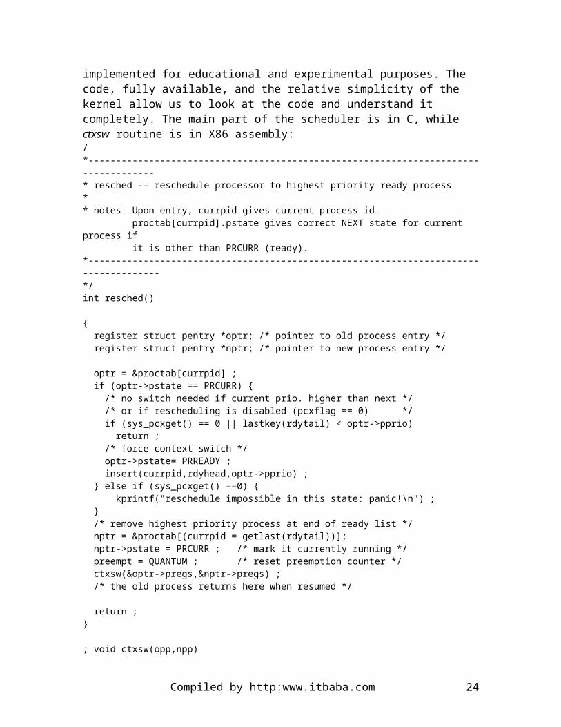
To appreciate the elements of context switches, it is better to look at a real example. A small kernel and some OS functions called XINU (UNIX spelled backwards) was implemented for educational and experimental purposes. The code, fully available, and the relative simplicity of the kernel allow us to look at the code and understand it completely. The main part of the scheduler is in C, while ctxsw routine is in X86 assembly: /*------------------------------------------------------------------------------------* resched -- reschedule processor to highest priority ready process** notes: Upon entry, currpid gives current process id. proctab[currpid].pstate gives correct NEXT state for current process if it is other than PRCURR (ready).*-------------------------------------------------------------------------------------*/int resched()
{ register struct pentry *optr; /* pointer to old process entry */ register struct pentry *nptr; /* pointer to new process entry */
optr = &proctab[currpid] ; if (optr->pstate == PRCURR) { /* no switch needed if current prio. higher than next */
Compiled by http:www.itbaba.com 17

/* or if rescheduling is disabled (pcxflag == 0) */ if (sys_pcxget() == 0 || lastkey(rdytail) < optr->pprio) return ; /* force context switch */ optr->pstate= PRREADY ; insert(currpid,rdyhead,optr->pprio) ; } else if (sys_pcxget() ==0) { kprintf("reschedule impossible in this state: panic!\n") ; } /* remove highest priority process at end of ready list */ nptr = &proctab[(currpid = getlast(rdytail))]; nptr->pstate = PRCURR ; /* mark it currently running */ preempt = QUANTUM ; /* reset preemption counter */ ctxsw(&optr->pregs,&nptr->pregs) ; /* the old process returns here when resumed */
return ;}
; void ctxsw(opp,npp); char *opp, *npp ;;-------------------------------------------------------------------------------------; stack contents upon entry to ctxsw:; SP + 4 => address of new context stack save area ; SP + 2 => address of old context stack save area; SP => return address; The addresses of the old and new context stack save areas are relative to the DS ; segment register, which must be set properly to access the save/restore locations.;; The saved state consists of the current BP, SI and DI registers, and the; FLAGS register.;-------------------------------------------------------------------------------------_ctxsw proc near push bp move bp, sp ; frame pointer pushf ; flags save interrupt condition cli ; disable interrupts just to be sure push si push di mov bx, [bp+4] ; old stack save address mov [bx], sp mov bx, [bp+6] ; new stack save address mov sp, [bx] pop di pop si popf pop bp ret_ctxsw endp;-------------------------------------------------------------------------------------
Compiled by http:www.itbaba.com 18

Consider what happens to the currently executing process during a context switch. Often, the currently executing process remains eligible to use the CPU even though it must temporarily pass the control to another process.In such situations, the context switch must change the current process state to PRREADY and move it onto the ready list, so it will be considered for CPU service again later.
How does resched decide whether to move the current process onto the ready list? It does not receive and explicit parameter telling the disposition of the current process. Instead, the system routines cooperate to save the current process in the following way: if the currently executing process will not remain eligible to use the CPU, system routines assign to the current process' pstate field the desired next state before calling resched. Whenever resched prepares to switch context, it checks pstate for the current process and makes it ready only if the state still indicates PRCURR.
In some situations it is necessary to suspend rescheduling while critical system activities are taking place. Suspension of rescheduling makes it possible for one process to have exclusive use of the CPU even when interrupts are enabled. The procedure sys_pcxget returns a non-zero value if rescheduling is permitted and returns zero otherwise. If the current process calls resched when rescheduling is not permitted, the procedure returns immediately. Since any return from resched must leave the process in the current state, it is an error is a process enters the scheduler when scheduling is suspended and the process is not the current process.
Resched completes every detail of scheduling and context switching except saving and restoring machine registers and switching stacks (can't be done in C or any other high level language, because they use the stack themselves). It selects a new process to run, changes the table entry for the new process, removes the new process from the ready list, marks it current, and updates currpid. It also resets the preemption counter. Finally, it calls ctxsw to save the current registers, switch tasks, and restore the registers for the new process.
The code for ctxsw is, of course, machine-dependent. When it switches processes, the FLAG register must be saved since it contains the interrupt state of the process. The other registers that must be saved are BP, SI, and DI, since C procedures assume that these will not change across procedure calls.
The code of ctxsw reveals how to resolve the dilemma caused by trying to save registers while a process is still using them. Think of an executing process that has called resched, which in turn called ctxsw. Instead of trying to save registers explicitly as the process executes, ctxsw captures the value of the stack pointer precisely when the registers (including the IP and FLAGS) are already on the stack as a result of the code in ctxsw. This freezes the stack of the process as if it were in the midst of executing a normal procedure. Then ctxsw restores the stack pointer to that of another frozen process; ctxsw restores the registers and returns normally to resume execution of the other process.
Compiled by http:www.itbaba.com 19

It is interesting to note that all processes call resched to perform context switching, and resched calls ctxsw, so all suspended processes will resume at the same place: just after the call to ctxsw. Each process has its stack of procedure calls, however, so the return from resched will take them in various directions. Note also that if the two pointers passed to ctxsw are equal (like a context switch to oneself) then ctxsw will simply return to the caller with no change.
CS305b OPERATING SYSTEMS
1. Threads
Threads are a somewhat new idea in OS. They are a form of process but they do not possess all the attributes of classical processes. The existence of the following two facts and their independence leads to the concept of a thread:
A process possesses resources The execution of a process follows a path in the code
Hence a process can be a object which has resource ownership whereas a thread becomes a unit of dispatching. In that light we can say that:
Process has: o Virtual addressing space for its image
Compiled by http:www.itbaba.com 20

o Various resources Thread has:
o Execution state o Saved thread context when not running o Execution stack o Per-thread static storage
2. The Motivation for Threads
There are tremendous advantages, from an OS point of view, to implement threads. Here is an incomplete list if these advantages:
It is faster to create and terminate threads than processes. Threads share process resources and hence less security is needed between
threads originating from the same process. If many instances of a process need to be run concurrently, only one process
image is needed in memory.
There are also some drawbacks with implementing threads. They are related to the fact that some process states apply only to processes, or only to threads or both:
Swapping a process means that its image goes onto the swap partition of the disk and this stops all associated threads.
In general, we can say that all process states will impact the behavior of threads. However, most process states apply to threads, exception made of suspended and swapped.
3. Operations on Threads
Operations on threads are similar to those on processes. It is in their implementation that they differ most, however. Here is a list of them:
Spawn: That is the thread creation mechanism, analogous to fork in UNIX. Block: The result of an event wait, such as an I/O operation. Unblock: Occurrence of awaited event. Finish: Exiting a thread.
4. Synchronization of Threads
Since threads share resources, their alteration will inevitably affect the behavior of other threads. For classical processes, the synchronization mechanisms are for system resources and their sharing. With threads, it is a little different. All threads emanating from the same process share all the resources of that process, at all times. The need for synchronization is even greater here, in terms of the frequency that threads have to resort to it.
5. User and Kernel Threads
Compiled by http:www.itbaba.com 21

The traditional situation in UNIX and in Linux is to have what is called kernel threads. That is to say, all the thread management happens in the kernel. Potentially, all user processes can be programmed to be threaded. The kernel can then schedule multiple threads from the same process onto more than one processor.
In the user thread approach, the situation is such that the kernel is not aware of the existence of threads (it does not implement them). If a user process wants to be threaded, then it has to programmed with a thread library that implements threads. It seems that the kernel thread approach is a superior one, as it is more general.
6. Linux Threads: The __clone System Call
CLONE(2)
NAME
__clone - create a child process
SYNOPSIS
#include <sched.h>
int __clone(int (*fn) (void *arg), void *child_stack, int flags, void *arg)
DESCRIPTION
__clone creates a new process like fork(2) does. Unlike fork(2), __clone allows the child process to share parts of its execution context with its parent process, such as the memory space, the table of file descriptors, and the table of signal handlers. The main use of __CLONE is to implement threads: multiple threads of control in a program that run concurrently in a shared memory space.
When the child process is created, it executes the function application fn(arg). The fn argument is a pointer to a function that is called by the child process at the beginning of its execution. The arg argument is passed back to the fn function.
When the fn(arg) function application returns, the child process terminates. The integer returned by fn is the exit code for the child process. The child process may also terminate explicitly by calling exit(1) or after receiving a fatal signal.
The child_stack argument specifies the location of the stack used by the child process. Since the child and parent processes may share memory, it is not possible in general for the child process to execute in the same stack as the parent process. The parent process must therefore set up memory space for the child stack and pass a pointer to this space to __clone. Stacks grow downwards on all processors that run Linux (except the HP PA
Compiled by http:www.itbaba.com 22

processors), so child_stack usually points to the topmost address of the memory space set up for the child stack.
The low byte of flags contains the number of the signal sent to the parent when the child dies. flags may also be bitwise-or'ed with one or several of the following constants, in order to specify what is shared between the parent and child processes:
CLONE_VM
If CLONE_VM is set, the parent and the child processes run in the same memory space. In particular, memory writes performed by the parent processor by the child process are also visible in the other process. Moreover, any memory mapping or unmapping performed with mmap(2) or munmap(2) by the child or parent process also affects the other process.
If CLONE_VM is not set, the child process runs in a separate copy of the memory space of the parent at the time of __clone. Memory writes or file mapping/unmapping performed by one of the processes does not affect the other, as in the case of fork(2).
CLONE_FS
If CLONE_FS is set, the parent and the child processes share the same file system information. This includes the root of the file system, the current working directory, and the umask. Any call to chroot(2), chdir(2), or umask(2) performed by the parent or child process also takes effect in the other process.
If CLONE_FS is not set, the child process works on a copy of the file system information of the parent at the time of __clone. Calls to chroot(2),chdir(2), umask(2) performed later by one of the processes does not affect the other.
CLONE_FILES
If CLONE_FILES is set, the parent and the child processes share the same file descriptor table. File descriptors always refer to the same files in the parent and in the child process. Any file descriptor created by the parent process or by the child process is also valid in the other process. Similarly, if one of the processes closes a file descriptor, or changes its associated flags, the other process is also affected.
If CLONE_FILES is not set, the child process inherits a copy of all file descriptors opened in the parent process at the time of __clone. Operations on file descriptors performed later by one of the parent or child processes do not affect the other.
CLONE_SIGHAND
If CLONE_SIGHAND is set, the parent and the child processes share the same table of signal handlers. If the parent or child process calls sigaction(2) to change the behavior
Compiled by http:www.itbaba.com 23
associated with a signal, the behavior is also changed in the other process as well. However, the parent and child processes still have distinct signal masks and sets of pending signals. So, one of them may block or unblock some signals using sigprocmask(2) without affecting the other process.
If CLONE_SIGHAND is not set, the child process inherits a copy of the signal handlers of its parent at the time __clone is called. Calls to sigaction(2) performed later by one of the processes have no effect on the other process.
CLONE_PID
If CLONE_PID is set, the child process is created with the same process ID as its parent process. If CLONE_PID is not set, the child process possesses a unique process ID, distinct from that of its parent.
RETURN VALUE
On success, the PID of the child process is returned in the parent's thread of execution. On failure, a -1 will be returned in the parent's context, no child process will be created, and errno will be set appropriately.
ERRORS
EAGAIN Too many processes are already running.
ENOMEM __clone cannot allocate sufficient memory to allocate a task structure for the child, or to copy those parts of the parent's context that need to be copied.
BUGS
As of version 2.1.97 of the kernel, the CLONE_PID flag should not be used, since other parts of the kernel and most system software still assume that process IDs are unique.
There is no entry for __clone in libc version 5. libc 6 (a.k.a. glibc 2) provides __clone as described in this manual page.
CONFORMING TO
The __clone call is Linux-specific and should not be used in programs intended to be portable. For programming threaded applications (multiple threads of control in the same memory space), it is better to use a library implementing the POSIX 1003.1c thread API, such as the LinuxThreads library. See pthread_create(3thr).
This manual page corresponds to kernels 2.0.x and 2.1.x, and to glibc 2.0.x.
Compiled by http:www.itbaba.com 24

CS305b OPERATING SYSTEMS
1. Symmetric Multiprocessing
There are two popular approaches to multiprocessing. SMPs (Symmetric Multi Processors) are machines that have many CPUs that can be running user processes or kernel processes. Generally, the Process Management for such architectures is complicated by coordination and synchronization issues not found with mono-processor machines.
We also find clusters, which are networked computers. The main difference here is that the cluster itself does not have a central memory. Each computer within the cluster has its own memory and synchronization issues are dealt with message passing over the network.
One of the main advantages with SMPs is, of course, the parallelism that they offer. This is especially true for threads, which are meant to run in parallel when originating from the same process.
Compiled by http:www.itbaba.com 25

There are, however, increased difficulties in the management of SMPs. For instance, the kernel code must be reentrant (many processors executing the same kernel routine); data structures must be shared while keeping their integrity; and scheduling can potentially be done by every processor. The memory management is also complicated by the many cache memories and the write policies that are associated with them.
2. Micro-kernels
A micro-kernel is the center of an Operating System that contains only essential core functions, such as hardware-dependent code, process management, and a few other basic components of an OS. This form of OS architecture has a number of advantages over the traditional, layered one:
A uniform interface is presented to both OS and user processes. Adding functionality amounts to adding OS drivers and daemons. Portability is greater, since only the micro-kernel has hardware-dependent code. A smaller core implies a smaller number of bugs and defects.
3. Mutual Exclusion and Synchronization
Process synchronization is vital when we need more than one process to solve a problem or to carry through a task. A good example of this is the producer/consumer problem where producer processes produce something that is consumed by the consumer processes. The need for synchronization here is due to the fact that a process cannot consume something that has not been produced.
In addition, there are resources that cannot be used by more than one process at once. These are memory locations, some I/O resources, etc. This aspect of the problem brings us to define the principle of mutual exclusion, which is a critical section where a process will have a unique access to a system resource. Hence, for a given resource, only one process at a time can be in its critical section, among the competing processes.
Mutual exclusion creates the possibility for deadlocks, which are situations where processes are interlocked in their demands for resources. One can imagine two processes P1 and P2, each possessing a resource, say P1 has R1 and P2 has R2. Now, if P1 needs R2 and P2 needs R1 for completing their work, there will be a deadlock. This kind of problem is generally unavoidable. There are algorithms for detecting and preventing deadlock situations. However, they are not implemented in general-purpose OS like Linux, Unix, or VMS.
In addition, mutual exclusion brings the problem of starvation. We say that there is starvation if a process cannot be guaranteed access to a resource in a finite amount of time. This problem is avoidable and modern OS do not have their kernel processes subjected to that type of problem.
4. An Example of Mutual Exclusion
Compiled by http:www.itbaba.com 26

void p(int i) { while (TRUE) { EnterCritical(i) ; /* critical section */ ExitCritical(i) ; }}
void main() { for (i = 0 ; i < N ; i++) { fork(p(i)) ;}
This example shows that if EnterCritical allows only one process at a time to go further, then the principle of mutual exclusion is implemented among the N processes that are created (forked) by the main program.
A mutual exclusion is supported by shared memory in the examples that we are investigating. That is to say, a number of processes can, by sharing access to some variables among themselves, synchronize their execution to create a mutual exclusion.
However, any viable solution to the problem of mutual exclusion must have a number of properties that we list here:
The critical section of a process must have a finite execution time. A process that demands to enter its critical section should be able to do so in a
finite time. With no processes executing a critical section, a process demanding it should get
access to it immediately. A process which halts in a non-critical section of its code should have no
influence on the execution of other processes, as far as their mutual exclusion is concerned.
The protocol to enter in critical section should be symmetric among processes.
There are three ways of providing processes with a mutual exclusion mechanism: With software With hardware With a combination of both
We examine these three different ways and evaluate their respective merits.
5. Mutual Exclusion Implemented with Software
Here is probably what a first draft would look like if we were to code a solution to the mutual exclusion problem:
Shared memory: Integer variable turn ;
P_0:
Compiled by http:www.itbaba.com 27

while (turn != 0) ;/* critical section */turn = 1 ;
P_1:while (turn != 1) '/* critical section */turn = 0 ;
This solution actually creates a mutual exclusion. That is to say, when P_0 is in critical section, P_1 cannot reach its own, and conversely. However, careful examination will show that for P_1 to go in critical section, then P_0 must have been in its own one first. This is caused by the fact that, in this solution, a process must wait for turn to be equal to the process number. Hence, this solution creates starvation.
A viable solution (1965) would look like:
void P_0()while (TRUE) { flag[0] = TRUE ; while (flag[1] == TRUE) { if (turn == 1) { flag[0] = FALSE ; while (turn == 1) ; flag[0] = TRUE ; } } /* critical section */ turn = 1 ; flag[0] = FALSE ;}
Of course, this solution has disadvantages:
It implies busy waits. The processes will use the CPU to wait for their mutual exclusion.
This solution will not work in an SMP-type machine. It is cumbersome and not really elegant.
6. Mutual Exclusion Implemented with Hardware
There are two ways of doing critical sections with the material of a computer. The first one involves disabling all interrupts:
while(TRUE) { disable_interrupts() ; /* critical section */ enable_interrupts() ; }
Compiled by http:www.itbaba.com 28

This solution might actually be too strong for the kind of problem we are trying to solve. In fact, while a process in in critical section, there is no possibility for the scheduler to pass the processor to another process (which does not want to acquire the resource this process has). So this solution prevents multiprogramming when a process is in its critical section. In addition, it means that the ability to enable and disable interrupts is available to user processes (if, of course, the OS wants to offer them a mutual exclusion mechanism). Consequently, a user process could steal CPU usage forever by simply disabling the interrupts permanently.
A second solution involves a special processor instruction called test and set. In the design of software solutions to mutual exclusion, we have noted that one of the problems was that a process could get interrupted in between testing and setting the value of a shared variable. To avoid this, a test and set instruction can be used. Of course, since the testing and the setting happen within the same processor instruction, it cannot be interrupted in the middle. A mutual exclusion using this mechanism would look like:
while(TRUE) { while (!testset(turn)) ; /* critical section */ turn = 0 ; }
There are two problems with this solution. First, there is busy waiting and starvation is possible, since the choice of the next process to enter in critical section is completely arbitrary.
7. Mutual Exclusion Implemented with Semaphores (Dijkstra, 1965)
struct semaphore {int count ;q_type q ;}
void wait(semaphore s) { disable_interrupts(); s.count-- ; if (s.count < 0) { enqueue(getpid(),s.q) ; } enable_interrupts() ;}
void signal(semaphore s) { s.count++ ; if (s.count <= 0) { dequeue(s.q,FIFO) ; }}
There are various types of semaphores. Let's define them:
Compiled by http:www.itbaba.com 29

Strong semaphore: Encodes the queueing policy. Weak semaphore: Does not encore queueing policy. Binary semaphore: The semaphore's integer variable can only be 0 or 1.
Here is the producer/consumer example coded with semaphores:
void prod() { while(TRUE) { /* critical section */ produce(); /* end of critical section */ signal(produced) ; wait(consumed) ; }}
void cons() { while (TRUE) { wait(produced) ; /* critical section */ consume() ; /* end of critical section */ signal(consumed) ; }}
main() { semaphore produced = 0, consumed = 0 ;
fork(prod()) ; fork(cons()) ;}
Because semaphores employ a queueing strategy, there is no busy waiting, and the interrupts are disabled only for a short, finite amount of time. In addition, since wait and signal are operations that are provided by the OS, there is no user process that can gain access to interrupt control.
Semaphores constitute the classical and current way in which Operating Systems provide mutual exclusion mechanism for user processes.
Compiled by http:www.itbaba.com 30

CS305b OPERATING SYSTEMS
1. Message Passing
As semaphores are shared integer variables with a number of atomic operations defined on them, then can be considered as a form of interprocess communication for synchronization.
Operating Systems also provide more direct means of communication between processes. For instance, message passing is a technique that allows processes to send and receive messages. The type of messages can be arbitrary, as it is usually data dumped in some shared location (memory).
The two message passing operations are usually defined as send(destination,message) and receive(source,message). They can be blocking or non-blocking and the Operating System sometimes leaves this choice to the user of these system calls. The notion of blocking calls here for message passing is essential: you can't receive a message that has not been sent. Let's look at possible blocking schemes for the two system calls send and receive:
Compiled by http:www.itbaba.com 31

send(destination,message): The process that is sending a message can be blocked until it is received by the destination process. Alternatively, the sending process may not block on a call to send, assuming that the message will be received.
receive(destination,message): If the process calling receive has a message to read, then it makes sense for this call to be non-blocking. However, there could also be reasons (this depends on what we want to do with the processes) for the process to wait until a message is sent (blocking call).
To summarize we have: Blocking send() and receive(): There is tight synchronization between processes
and this type of message passing is called rendez-vous. Non-blocking send(), blocking receive(): This is the most common message
passing technique. It can be cleanly implemented if messages can pile up before they are read by the destination process. So, it is the mailbox principle. As well, this is a scheme sufficient to create mutual exclusions between processes.
Non-blocking send(), non-blocking receive(): Nobody waits here, but it is easy to see that some messages can be lost.
2. Message Addressing, Format, and Queueing
With messages, as well as with letters, addressing is an issue. For message passing, we know two forms of addressing: direct, and indirect.
Direct addressing: send() specifies destination process. receive() may or may not designate a sender.
Indirect addressing: Messages are passed within a data structure. They could be mailboxes. So, a process needs a mailbox number, not a process id to send a message. It is the same for receiving, where the process does it from a designated mailbox.
Typically, a message will have the following form and contents: Message type Destination id (pid or mailbox number) Source id (pid or mailbox number) Control information (whatever is needed) Message contents
In addition, since messages can pile up in a mailbox or somewhere else when the send() call is non-blocking, they need to be queued. Generally, a FIFO queue is used, to respect arrival order. However, it is also possible to have message priorities and therefore the queue would be sorted according to this.
3. Mutual Exclusion with Messages
Compiled by http:www.itbaba.com 32

Here is an example of mutual exclusion realized with message passing: #define N ...mailbox mutex ;
void p(int i){ message msg ;
while (TRUE) { receive(mutex,msg) ; /* critical section */ send(mutex,msg) ; }}
void main() { create_mailbox(mutex) ; send(mutex,NULL) ; for (i= 0 ; i < N ; i++) { fork(p(i)) ; }}In this case, only receive() needs to be a blocking call. The call send(mutex,NULL) will initialize the mailbox as empty and the receive() calls will block on an empty mailbox.
Compiled by http:www.itbaba.com 33

CS305b OPERATING SYSTEMS
1. Concurrency
When processes cooperate and compete for resources, there is always the possibility that things go wrong and that processes interlock themselves in the attempt to acquire shared resources. When processes get interlocked and cannot execute at all, we call this a deadlocked state. It is a permanent blocking of processes. For this to happen, processes must be competing for resources. There are two classes of resources: those that are consumable and those that are not. Here is the distinction:
Reusable resources: They are used without being depleted after use. Examples are the CPU, I/O channels and devices, memory, etc.
Consumable resources: They usually are created and then destroyed after use. Examples are: signals and messages, information in I/O buffers, etc.
Deadlocks can happen with both types of resources. The required conditions for deadlock are
Mutual exclusion Hold and wait No preemption Circular wait
Compiled by http:www.itbaba.com 34

Note that these are desirable conditions, as we want processes to cooperate and synchronize themselves. Since, we can have deadlocks, then we must find ways of preventing them when this is required. There are two ways:
Prevent occurrence of deadlock conditions Prevent circular waits
We are going to examine two deadlock avoidance mechanisms.
2. Deadlock Avoidance Strategy
This type of method allows the existence of deadlock conditions. It simply schedules resource usage is such a way as to avoid deadlocking processes. We can come up with a method that denies process execution if it is putting the system at risk for deadlocks. This method is called Process Initiation Denial. It works as follows:
n: Number of processes m: Number of resource types R = (R1, R2, ..., Rm) is the resource vector. It indicates the total number of
instances for each resource type. A = (V1, V2, ..., Vm) is the available vector. It indicates how many instances of
each resource type are unused. Claim: Claim matrix, specifies maximum requirements for each resource type
and for each process:
C11 C12 ... C1m
C21 C22 ... C2m ... ... ... ... Cn1 Cn2 ... Cnm
Alloc: Allocation matrix, describes current resource use for each resource type and for each process:
A11 A12 ... A1m
A21 A22 ... A2m ... ... ... ... An1 An2 ... Anm
There are some formulae that describe some quantities. For example: Ri = Vi + sum for k=1 to n of Aki
This simply states that the total number of instances of a resource type is equal to the sum of allocated resource instances and available resource instances.
Cki <= Ri, for all k,iA process cannot claim more resources than those in existence.
Aki <= Cki for all k,iNo process is given more resources of any type than it claimed to need.
Compiled by http:www.itbaba.com 35

We can now examine the deadlock avoidance policy, which states: Start process Pn+1 only if:
Ri >= C(n+1)i + sum for k=1 to n of Cki, for all i
In other words, start process if the number of resources Ri is greater or equal to the sum of its claim for resource i and the other processes' claims for that same resource i, for all resources.
The strategy here is sub-optimal because processes are assumed to make their maximum claim all at the same time, which is typically a rare event.
Instead of having a process initiation denial, we can work with resources and come up with a Resource Allocation Denial policy (Banker's algorithm). Here are some definitions that we will need to explain the policy:
State: Current allocation of resources to processes. Safe state: A state in which there is at least one sequence of process execution
that does not result in deadlock (all processes can be run in a certain order).
Here is an example, using the same data structures as the preceding method: Claim:
3 2 2
6 1 3 3 1 4 4 2 2
Alloc:
1 0 0
6 1 2 2 1 1 0 0 2
Question: Is this a safe state? That is: can a process be run to completion with the resources that are available?
Answer: Only p2 can have its claim met. So we run it and system state becomes: Claim:
3 2 2
0 0 0 3 1 4 4 2 2
Alloc:
Compiled by http:www.itbaba.com 36

1 0 0
6 1 2 2 1 1 0 0 2
And the vector A, representing available resources, becomes:(0,1,0) + (6,1,3) = (6,2,3)
Question: What other processes can be run? Answer: P1, P3, P4 can be run, in the same way we ran P2.
Compiled by http:www.itbaba.com 37

CS305b OPERATING SYSTEMS
1. Deadlock Avoidance and Prevention
Deadlock prevention mechanisms are very conservative in their approach, and therefore a little inefficient. We might prefer to perform deadlock detection instead. Such methods do not impose a limit on process resource requirements, and do not restrict the actions of processes. Let's examine the properties of deadlock detection:
Resource requests are granted whenever possible The Operating System periodically checks for circular wait conditions A check for deadlock can be made each time a resource is claimed by a process The algorithms can be implemented in a simple way because the checks are based
on incremental changes of the system.
2. Deadlock Detection Algorithm
We have the following data structures for this algorithm: Alloc: Allocation matrix, as before. A: Available vector. W: Work vector. Q: Matrix defined such that Qij is the amount of resources of type j requested by
process i.
The algorithm proceeds with marking processes that are not deadlocked. Here are the steps involved:
1. Mark each process Pi that has a complete row of zeroes in matrix Alloc; 2. Set W to A; 3. find i such that Pi is unmarked and row i in Q is less than or equal to W; 4. If no such row can be found, terminate the algorithm; 5. If row is found, mark Pi and add its corresponding row in Alloc to W; 6. Go back to step 3 of the algorithm;
There is a deadlock if and only if there are unmarked processes left at the end of executing this algorithm. Further, each unmarked process is in a deadlock.
3. Strategies for Recovery from Deadlock
There are various ways of dealing with this problem. Depending on context, we might want to adopt one of the following strategies:
Compiled by http:www.itbaba.com 38

Abort all deadlocked processes Rollback deadlocked process and restart Apply successive aborts, one deadlocked process at a time, until deadlock
disappears Successively preempt resources from deadlocked processes, and apply partial
rollback to where they were in their execution before they gained the preempted resources.
As we can easily see, each method has drawbacks. The choice of one method should be driven by the type of tasks that are carried out by the deadlocked processes.
Compiled by http:www.itbaba.com 39

CS305b OPERATING SYSTEMS
1. Memory Management
Memory management is required in Operating Systems because processes require protection from each other, and the sharing of memory. There are various technical issues, such as logical and physical organization, relocation of code, address binding, etc. We are going to examine these concepts and issues in some detail.
2. Memory Protection
Memory protection is an advanced concept in memory management. Since process location in physical memory is unpredictable, due to virtual memory systems, then protection cannot be achieved at compile time. All the memory accesses performed by a running process need to be checked at run-time. The Operating System itself cannot accomplish this: when a process is running, the system does not have the control. Furthermore, it is illusory to think that we'd keep efficiency of access if each memory access had to generate an interrupt so that the Operating System could validate it. Some material solution has to be present within the hardware to perform this.
3. Memory Sharing
The sharing of memory allows two or more processes to share one or more regions of memory. Somehow, if processes are going to cooperate, synchronize, or compete among themselves, then they must have a means of communication. What else other than shared memory can do this in a mono-processor machine?
4. Logical Organization
The compiling of programs, applications, and other pieces of software must somehow resolve for memory references that are made by the code. For example, suppose you compile the following instruction: a = b ;a and b are variables in the program that have to be bound to some memory location when the program gets to be executed. So how is the compiler to do this if the location in memory of the resulting process is not predictable? Simply, the compiler translates the variable addresses as offsets into the code data part of the process. In this way, when the program is loaded in memory and becomes a process, a base data register is loaded in the CPU with the physical address where the data has been loaded in memory. Then, when the program makes a reference to memory, the physical address is translated as the offset generated by the compiler added to the address contained in the base data register of the CPU. This is called run-time address binding and it requires hardware to be accomplished correctly.
Compiled by http:www.itbaba.com 40

This mechanism also allows a process to be swapped out of memory onto the swap space of the disk and be reloaded at a different physical memory location. At reload time, the only thing that has to change is the base address contained in the base data register. It needs to be set to the start address of the new physical memory location of the data part of the process.
5. Memory Partitioning
Memory partitioning is a physical memory issue that must be dealt with if we want to eventually implement virtual memory. The memory can be divided into fixed partitions (we will call them memory frames later on) or it can be divided into dynamic partitions (and we will call those segments later on). The two methods involve some fragmentation, which is defined as the impossibility of using some parts of the memory. There are two types of fragmentation:
Internal fragmentation: This occurs when the memory is divided into partitions of static, equal size. If the operating system is loading a program into a number of partitions, then the last partition used for it will probably not be fully utilized. This waisted space is called internal fragmentation.
External fragmentation: This occurs when the memory is divided into partitions of dynamic, varying sizes. When some processes are loaded and taken out of memory using segments that perfectly fit their sizes, there comes a time when the memory has parts of it that are free but too small to contain any useful segments This is called external fragmentation.
5.1. Simple Paging
In simple paging, the memory is divided into a set of equal size frames. Each process is divided into a set of pages, that have the same size as the frames. The process pages are loaded into the frames of the memory. These frames containing the process pages do not need to be stored in a contiguous manner. The loaded frames can be anywhere in physical memory. With this scheme, there is little internal fragmentation and no external fragmentation at all.
5.2. Simple Segmentation
In this scheme, a process is divided into a number of segments, and these segments are loaded into memory partitions of variable size. In this case, there is no internal fragmentation as the partitions fit exactly the size of the process segments. However, there is external fragmentation.
5.3. Virtual Memory Paging
In this scheme for memory management, the operating system does not require that all the pages of process be loaded to start its execution. In this way, the process to execute can be significantly larger than the size of the physical memory and still be executed completely, if the system only keeps the required pages into frames for its execution at
Compiled by http:www.itbaba.com 41

any one time. Of course, this makes the management of memory a bit more complex, but the capability of running processes that are larger than the size of the central memory is precious.
5.4. Virtual Memory Segmentation
In this case, the operating system does not require that all the segments of a process be loaded to commence its execution. The technique really is similar to virtual memory paging, with the difference that the segments have variable length. Again, the process size can be much larger than the physical memory size.
6. Virtual Memory Systems
All virtual memory systems aim at providing the user processes with an addressable space that is much larger than the physical size of the memory. To do this, we need to translate memory references (accesses) a process makes at run-time. In addition, we require a mechanism for having a process image that can be divided into a number of parts which do not need to reside in memory in a contiguous fashion. If these two characteristics are found in the hardware and managed by the operating system, then we can implement a Virtual Memory Management System. There are two serious advantages to these systems:
We can have more resident processes Processes can be very large
The principle of locality allows us to implement virtual memory. This principle simply states that a sequence of memory accesses has a good probability of happening close to each other in memory. Mostly avoiding having to go from page to page often and creating page faults (which we define later).
6.1. Paged Virtual Memory Systems
The components of a paged virtual memory system are: Each process has a page table which contains the frame number of the page in
memory The page table is located in main memory (at least partially) There is a P-bit for each page that indicates if the page is loaded in memory There is an M-bit that indicates if the page has been modified since its loading in
main memory (also called a dirty bit)
In the simplest virtual memory systems, the address translation can be viewed as a process involving the relative addresses generated by the compiler of the code into the absolute addresses when the program is a running process. In simple terms, this can be described as:
The virtual (relative) address to be translated in considered to be made of two parts. The first part, consisting of the most significant bits, is called the page number. The remaining least significant bits are called the offset within that page.
Compiled by http:www.itbaba.com 42

The translation process takes the page number, looks up in the process' page table if the page in question is loaded in memory. If so, the table provides the physical address of the frame containing that page. The offset within that page is added to the address of the frame and the absolute address is obtained.
If the frame number cannot be found in the page table, it means that the page does not reside in main memory and needs to be loaded.
This is called a page fault. The way this is dealt with is through an interrupt that tells the operating system to load the page in a free frame. After this is done, the process can complete its memory access into the newly loaded page.
This simple scheme has a serious problem, only aggravated by the constantly growing memory sizes: the page table is usually a very large data structure because there are as many entries in it as there are pages in the virtual addressing space, and with the table residing in main memory, we might actually reduce system performance.
A solution to this problem is to only keep a part of the table inside the main memory. To do this, it is reasonable to store the table in the same virtual addressing space as the processes. The requirements to store the page table in virtual memory instead of main memory call for a table of page tables. It this scheme, we define a root page table the size of a frame which is always resident in memory and indicates where the page table for the process is. Hence, there could be a page fault trying to gain access to the page table, causing the operating system to load the required part of the page table into a memory frame. This is called a 2-level paged virtual memory system. Now that memories can be very large, 3-level systems have appeared, such as in Linux for the 64 bit Alpha processors.
Other solutions to the page table size problem have been implemented. One of them is to have a page table that as a number of entries equal to the number of frames in main memory. When a memory reference is made by a process, the page number part of its virtual address is hashed to give a page table entry. If the the page is found at this page table entry, then it means the page is in memory. Collisions in the hash table are usually handled by simple chaining. Collisions will be unavoidable because the number of virtual memory pages will be greater than the number of entries in the page table, which corresponds to the number of memory frames. This sort of arrangement is called an inverted page table.
In addition to this, Translation Lookaside Buffers have been used to speed up the address translation mechanism. They basically are a type of cache memory dedicated to paging management. They will contain a part of the page table and use associative memory to find page entries, which is much faster than conventional lookup methods.
6.2. Page Size Issues
In any paged virtual memory system, page size is a performance issue of importance. Let's examine this parameter in detail:
Compiled by http:www.itbaba.com 43

For a constant memory size, the smaller the page size is, the more page table entries we have, making the problem of page table sizes worse (except for inverted page tables, where the problem becomes one of increased hash table collisions).
The smaller the pages, the more page faults the operating system will have to resolve, which is time consuming and adds to the overhead of the system.
Internal fragmentation will get worse as page sizes increase. The rapid growth of main memory sizes also involves a growth in virtual memory
spaces. This implies that, for a constant page size, we must resort to more and more page table levels, again adding to the overhead of the memory system.
As we can see, such issues are important from the point of view of system performance and will keep to be, as long as the evolution of hardware keeps its current pace.
CS305b OPERATING SYSTEMS
1. Segmented Virtual Memory Systems
Compiled by http:www.itbaba.com 44

In segmented systems, the same principles behind virtual memory can be found. However, the difference is that processes are divided into segments, that are then loaded in memory as continuous chunks of memory. Compared with a paged system, the main differences are:
A segment table is used instead of a page table. For each segment table entry, there is one more piece of information that must be kept and that is the length of the segment.
Segments do not fit nicely as pages in frames all of the same size. Therefore segment placement and replacement algorithms are required.
The hardware is complicated by the fact that checking for illegal memory references outside a segment involves considering its length which is dynamic.
Segments can dynamically grow as the owner process runs, unlike pages in frames. If a segment gets to be too large for its placement in memory, then the operating system relocates it in a suitable memory location.
Segmented systems thus have advantages. To benefit from the in virtual memory systems, we can devise a segmented system in which segments are made up of pages. Using this strategy we get a 2-level virtual system with the highest level being a segment table and the lowest level being a page table. Each entry in the segment table would point to the page table containing the pages forming that segment. As with a pure paging system, the page table could also be stored in virtual memory. In such systems, a virtual address is divided in three fields: the segment number, the page number, and the offset in that page.
2. Some Examples of Existing Systems
In Solaris 2.x A paged virtual memory system is used and there is also a kernel memory allocator, for the special needs of the operating system. Under this scheme, user processes and kernel processes use two different memory systems.
The data structures in existence are:
Page table: One per process Disk block descriptor: Entry for each page in virtual memory describing the disk
copy of it Page frame data table: Describes all frames in main memory. The index is per
frame number Swap-use table: There is one such table per device, with one entry for each page
on the device.
The page replacement algorithm uses the page frame data table. All free frames are grouped in a list of free frames. When the number of free frames goes below a threshold, the kernel will steal a number of them for itself. The page replacement strategy is based on the clock policy:
Compiled by http:www.itbaba.com 45

It uses the reference bit in the page table entry (PTE) for each unlocked page in memory. The bit is set to 0 when the page is first brought in memory, and set to 1 each time a reference (read or write) is made to it.
The front hand pointer goes around the pages and sets the bit to 0 on each page. The back hand sweeps through pages and checks the bit. If it is set to 1, the page
was referenced since the front hand sweep. If bit is 0, then the page is placed on a page-out list.
The page-out list is used when the need to swap out pages arises.
In linux, the memory management system has a 3-level page structure, which is fully enabled on 64-bit processors (such a large addressable space calls for the 3 levels of page tables). This structure is collapsed to 2 levels on Intel's 32-bit processors. When the 3-level paging system is fully enabled, then a virtual address has four fields: three of them for the page tables and an offset, represented by the least significant bits of the address. In addition and unlike pure Unix systems, the page table mechanism is platform independent.
The page replacement algorithm is a variant of the clock algorithm. A byte is used to describe the time a page has been in memory, so it is more precise than systems using only one bit for this.
Typically, the information that will be found in a Page Table Entry (PTE) is:
page frame number age copy on write (for when the page is shared with other processes) modify (dirty bit) reference valid (indicates if page is in main memory) protect (indicates if the page is write-protected)
3. Summary of Virtual Memory Management
As we have seen, there is a number of issues dealing with both hardware and software. On the hardware side, we find the various paging mechanisms along with segmented memory, multiple level paging, and Translation Lookaside Buffers (TLBs). The software issues that an operating system must deal with are the placement and replacement policies, resident set management, and cleaning policies. Last update 10/03/02
Compiled by http:www.itbaba.com 46

CS305b OPERATING SYSTEMS
1. Processor Scheduling
Compiled by http:www.itbaba.com 47

Processor scheduling is the key to multiprogramming. Its role is to assign processes to be executed so that some criteria on efficiency are met. These criteria will vary, depending on the type of process load a system has, its number of users, whether processes are CPU or I/O bound, etc. There are four different types of scheduling in a system: long-term, medium-term, short-term and I/O scheduling.
Long-term scheduling: This is when the system determines which programs are admitted as processes to be run eventually. The criteria at play here might be process priority, expected run-time, number of I/O requests, etc. However, in the type of systems we use here (Unix), the long-term scheduler refuses entry to a process when resources are exhausted or the number of users is at its maximum. In general, this is the type of long-term scheduling that is implemented.
Medium-term Scheduling: This is the type of scheduling which decides whether a process should be in the ready queue or in a wait, suspend, or sleep queue. This decision depends on processor load, process-triggered events (I/O and the like), and demands made on the virtual memory system.
Short-term scheduling: This part of scheduling is responsible for processor allocation to processes from the ready queue. The algorithms can be designed to meet a number of requirements, such as system throughput (number of finished processes per time unit), or response-time.
I/O Scheduling: This part takes care of processes in the various I/O waiting queues. It makes the decisions as to which processes are going to complete their I/O requests first based on a number of criteria, such as availability of devices, type of I/O request, amount of transferred data, etc.
2. Short-Term Scheduling: Process Priorities
The ready queue of an operating system can be an intricate data structure. Typically, processes will be scheduled according to a priority, represented by an integer, that indicates the urgency with which a process must gain the CPU.
To this effect, the ready queue, instead of containing processes of various priorities and having to be kept sorted, is implemented using an array of queues. Each position in the array is a queue of processes that have the same priority. When a ready queue is implemented this way, then the scheduler does not have to search among processes the one that is to execute next; it simply goes to the highest priority queue and picks the first process that happens to be there.
Of course, priorities cannot remain static throughout the lifetime of a process. It is easy to see that a process with a low priority would never execute, given a constant arrival of processes with higher priorities. Therefore, dynamic priority policies must be used.
Scheduling policies are usually implemented with a selection function, that the scheduler uses to choose the next process. Some of the relevant data for a process are:
w: The time a process has spent in the system e: Execution time so far
Compiled by http:www.itbaba.com 48

s: Maximum service time (a user supplied value, generally)
With this type of information on processes, comes a decision mode implemented into the scheduler. It can either be preemptive or non-preemptive.
Non-preemptive: The process with the CPU runs until it terminates, blocks to wait for an event, or requests a service from the operating system.
Preemptive: The process gets interrupted by a regularly scheduled clock tick and moved back to the ready queue to be resumed later. This mode is based on a periodical interrupt clock mechanism.
3. Choosing the Next Process
When the scheduler is invoked, it needs to figure out what process to pick next for the CPU. This can be done in a variety of ways, and various policies have been implemented in a number of operating systems. Let us examine them:
First-Come-First-Served (FCFS): o The process that has been the longest in the ready queue is selected o This method performs better for time-consuming processes o It is usually combined with a priority queue to improve service time
Round Robin: o Uses a periodical interrupt mechanism o Each time a scheduling interrupt occurs, the next process is chosen
according to FCFS o The frequency with which the interrupt is programmed is an important
parameter for both multiprogramming and scheduling overhead. o This policy proves effective in general-purpose systems. o It is also called time slicing
Shortest Process Next: o It is a non-preemptive policy o The process with the shortest expected running time is selected next o There is a need to know expected running time and this can be difficult to
determine o For regularly scheduled jobs, we may compute average running time,
using incremental formulae. However, this adds to scheduling overhead. Shortest Remaining Time:
o Preemptive version of Shortest Process Next. o The choosing policy is the same, but it is executed at every clock
interruption Highest Response Ratio Next:
o The scheduling policy minimizes a ratio such as r = (w+s)/s, where w is the time spent waiting for the CPU, and s is the expected service time
o The policy is to choose the next process as the one with minimal ratio r o This policy explicitly accounts for process age through w
Feedback: o If there is no indication on the expected running time of various processes,
then we cannot use SPM, SRT, or HRRN.
Compiled by http:www.itbaba.com 49
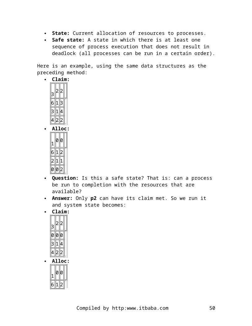
o We may, instead, penalize processes that have been running for longer o The more a process requires CPU time, the lower its priority gets, in this
policy o To implement this policy, preemptive scheduling and dynamic priority
settings are required o Each time a process gets the CPU for its quantum and releases it without
being finished, it is queued back to the next lower priority queue. o This policy favors short processes and stretches the wait for longer ones in
an unfair way. o To fix this, one can allow processes that have reached the lowest priority
queue to climb back again into the queues, according to some policy. Fair Share Scheduling:
o Group processes into sets o These sets could be formed on a per user basis or on a user group basis, as
well o Balancing the scheduling is performed with respect to these sets. o For instance, each user (or user group) is assigned a weighing of some sort
that defines the fraction of resources that corresponding processes may use o The scheduling is done with priorities and the formulae for a process j in a
group k would look like: CPUj(i) = CPUj(i-1)/2 GCPUj(i) = CPUj(i-1)/2 Pj(i) = BASEj + CPU(i-1)/2 + GCPUk(i-1)/(4*Wk)
where
CPUj(i) is a measure of CPU utilization by process j through interval i
GCPUk(i) is a measure of processor utilization of group k through interval i
Pj(i) is the priority of process j at the beginning of interval i (lower values mean higher priorities)
BASEj is the base priority for process j Wk is the weighting assigned to group k, with 0 <= Wk <= 1 and
the sum of Wk's over k is equal to 1.
As we can see, each process is assigned a base priority and the priority of a process is dynamically controlled by the above equations.
4. 4.3 BSD Unix Scheduling
Here we proceed to describe an example of the scheduling policy implemented in 4.3 BSD:
The quantum time is set to 1 second Priority is computed with respect to process type and execution history. The
equations governing their behavior are :
Compiled by http:www.itbaba.com 50

o CPUj(i) = CPUj(i-1)/2 o Pj(i) = BASEj + CPU(i-1)/2 + NICEj, where NICEj is a user supplied
value.
Each second, the priorities are recomputed by the scheduler and a new scheduling decision is made.
CS305b OPERATING SYSTEMS
1. Multiprocessor Scheduling
Usually, processes are not dedicated to processors in a multiprocessor machine. General solutions to the scheduling problem would not be available then. We have seen that on a
Compiled by http:www.itbaba.com 51

single processor machine, sophisticated algorithms for scheduling may improve performance. However, with multiprocessor computers, these refinements may lead to unnecessary scheduling overhead. As a matter of fact, maximum utilization of each processor is less of an issue in multiprocessors, where we tend to favor increased speed of execution through parallelism. In addition, the use of threads is a common way to achieve this parallelism effectively.
2. Process Scheduling
In a multiprocessor machine, the typical scheduling algorithms we find are rather simple. For instance, there can be a unique process queue, and each processor takes the first process from the queue and runs it.
This is an attractive scheme, for it is simple. However, it is easy to imagine how to slow down such a system. Given short execution time processes and a constant flow of them arriving in the queue, then all processors will have to contend for gaining access to the process queue to pick up their next process to run.
Other alternatives exist and they can be implemented simply. Each processor could have its own process queue and a centralized part of the operating system would equally distribute incoming processes to the queues.
3. Thread Scheduling
Here are the different approaches that have been investigated for thread scheduling on multiprocessor machines:
Load Sharing: o Thread load is distributed evenly across processors o There is no centralized scheduler o The shared process queue can be organized just as it is with mono-
processor systems o Mutual exclusion must be gained on the queue o If a great deal of cooperation among threads is needed, the performance
could degrade as all the threads from one application are not likely to each be running on a processor
o There exists three different models of load sharing: FCFS:Each thread from a job is placed in a shared queue where
processors can pick them up Smaller Number of Threads First: The shared queue is
organized per number of threads per process, as with FCFS, a job runs to completion or until it blocks
Preemptive Smaller Number of Threads First: Preemption based on number of threads, where a smaller number of threads indicate preemptive power
Compiled by http:www.itbaba.com 52

Gang Scheduling: Simultaneous scheduling of the threads making up a process. This approach minimizes switches and improves performance when tight cooperation among threads is required.
Dedicated Processor Assignment: This is an extreme form of gang scheduling. In this approach, a group of processors is dedicated to running an application (and its threads) until it is done. This approach is good for massively parallel machines where processor throughput is not so important. In addition, running a cluster of threads until final application completion is bound to eliminate scheduling overhead.
4. Real-Time Scheduling
Real-time scheduling is a reality of systems driving industrial processes, cars, robots, and embarked systems that have to react rapidly to changing conditions. In this sense, not only do results from the operating systems have to be correct, but they have to remain so under a great variety of conditions, characterized by external and somewhat unpredictable events. The types of real-time tasks are the following:
Hard real time: These tasks must meet their deadline for completion Soft real time: It is better if deadline met but, will not make the system fail
As well, there are unique requirements for real-time operating systems, in the areas of determinism (correctness of results under various conditions), responsiveness, control, and reliability.
Determinism: The need to achieve correct results no matter the situation Responsiveness: Time to service requests, and the effects of interrupt nesting Control: There is a need for fine grained control over task priority. Factors
having an effect on this type of control are: number of processes in main memory, paging parameters, swapping, priority allocation
Reliability: Rebooting a real-time machine is generally a bad idea.
5. Features of Real-Time Operating System
The important features of real-time operating systems are the following: Fast process switch: It is essential to give the CPU to a higher priority real-time
process very quickly. The scheduler is optimized to just do this. Minimal functionality: The more frills, the more bugs. Hence, most real-time
operating systems have just the right amount of functionality as to avoid bugs as much as possible.
Interprocess communication: Real-time processes often need to talk to each other as to coordinate operations in the right order. This communication must be fast and reliable.
Preemptive scheduling: The ability to give the CPU to a process, no matter what it is currently doing.
Compiled by http:www.itbaba.com 53

Interrupt disabling: To provide the operating system with the capability of running a process from start to end while ignoring external events.
Recovery: The ability of the operating system to save the day, should there be a software or hardware fault. In other words, let's not crash the plane just because the air conditioning process failed to get loaded in memory.
6. Deadline Scheduling
It is a normal and consequent attribute of real-time operating systems to schedule for deadlines. This type of scheduling uses task information such as:
Ready time: The time at which a task is ready to be run Starting deadline: The time at which a task must start to successfully complete Completion deadline: The time at which a task must complete in order to be
successful Processing time: The time a task needs to execute completely Priority: This is the same concept as with multiprogrammed, mono-processor
machines
7. Rate Monotonic Scheduling
This is the business of scheduling periodic tasks. The important parameters here are the task period T, which indicates the amount of time in between two scheduled runs of the task. If T is expressed in seconds, then it is easy to convert to Hertz: Hz = 1/T.
Let's suppose now that C is the execution time of a task with period T. Then the constraint C <= T comes naturally to mind and expresses the fact that a CPU cannot execute a 2 second-long task every second. With these variables defined we can also characterize CPU usage for a periodic task as U = C/T. In addition, if we have n periodic tasks to schedule, then we must also salsify this general statement: C1/T1 + C2/T2 + ... + Cn/Tn <= 1.
CS305b OPERATING SYSTEMS
1. I/O Management and Disk Scheduling
Input/Output or I/O, for short, is the ugly side of operating systems. First, since there is movement of data over possibly large distance compared with that between RAM and CPU, and maybe even mechanical movement involved (disk r/w head), then it is bound to be slow. In addition, the large variety of I/O devices, each calling for a device driver, makes it a programming mess (installing Linux on a top-of-line machine? Get a screwdriver, cause you'll need to change a few pieces of hardware).
Compiled by http:www.itbaba.com 54

There are three broad categories of I/O devices:
Machine readable devices: These are devices such as tapes and disks, etc. Communication devices: Network Interface Cards (NIC), etc. Human readable devices: Printers, CRTs, etc.
There is also three different ways of performing I/O inside a computer, such as programmed I/O, interrupt-driven I/O, and Direct Memory Access (DMA). Direct Memory Access is the most favored method, since it frees the CPU from the burden of transferring data from devices to memory, a lengthy process.
The logical structure of the I/O function in an operating system is generally layered. At the highest level of abstraction, there are two fundamental goals that must be achieved by the operating system. These are:
Efficiency: Since I/O is a bottleneck, the design of the operating system must be so that it does not render the I/O function significantly slower. Hence, extra care must be taken during design and implementation.
Generality: The programmers and end users should not have to deal with the particular type of I/O device they want to use. To that end, the operating system must provide services that make abstraction of the particulars of its I/O devices. For example, in Unix everything is treated as a stream of bytes, so that a common set of logical operations can be defined.
The Layers involved in I/O implementing these two goals are located at the logical, device, and hardware control levels. Here are their main functions:
Logical I/O: Provides logical services such as read, write, open, and close for all devices, no matter what they are. Of course, for some devices, some of these operations are not defined as they may have no meaning. They are nonetheless provided as routines with no functionality.
Device I/O: The commands coming from the logical I/O layer are transformed into sequences of I/O device transfer instructions, so as to get the I/O accomplished. If there is buffering, it is at this level that it is happening.
Hardware control: This is the layer at which the queuing and low-level scheduling of I/O operations is performed, including the reporting on device status.
2. I/O Buffering
Buffering is a technique that allows to decouple user process I/O from the I/O device itself. For example, a process can write to a disk and not have to wait for the actual data to be physically written on disk to go on doing other operations. This is a very common technique in operating systems and its purpose is to smooth out the rates of transfer, as some devices do go by bursts (disks do, for example).
Compiled by http:www.itbaba.com 55

I/O buffering will be implemented differently, depending on the device being buffered. For instance, some devices are block-oriented while others are stream-oriented. The buffering will then be done by blocks or by byte streams.
Block-oriented devices: Data transfers are performed by buffered blocks of constant size, corresponding to the block size on the device. For example, it is customary to have a disk block size of 512 bytes, which means that one cannot read just a byte. The whole block where the byte to read is must be entirely read into a block.
Stream-oriented devices: Transfers are performed with a flow (therefore the name stream) of bytes. These streams can be of any length, to accommodate the I/O requests. Examples include printers, communication ports, etc.
The most widely used buffering technique is circular buffering. The size of buffers is also determined with the peak data transfer of the device and the speed at which the operating system can consume the data from the buffers.
3. Disk Scheduling
You'd think that, with time, technology gets better. This is true, when the statement is not taken in a differential sense. For example, the speed of CPUs doubles every 18 months on average, whereas the increase in data access speed from disks is a lot slower than this. As a consequence, main memory access is four orders of magnitude faster than disk access, and this is going to get worse before it gets better. So algorithms for disk request scheduling are important. They must perform rapidly and fairly. Here is a list of the various types of lag times a disk access will show:
Seek time: Time needed to move the disk head to the required track (circle of sectors on disk surface).
Rotational delay:Time required for the desired sector on a track to show up under the r/w head. This depends heavily on the rotational speed of disks. 10,000 rpm seems to be the norm for server disks whereas 7,200 rpm is what you find in the typical Personal Computer (PC).
Transfer time:The time it takes to actually write or read something once the arm is on the right track and that the required sector goes under the the arm. This time depends on the rotational speed of the disk but also on how much "space" on the sector a byte takes. The transfer time is given by T = b/(rN), where b is the number of bytes to transfer; N is the number of bytes on the track; and r is the rotation speed in revolutions per second. Then it is easy to deduce that the total average access time is Ta = Ts + 1/(2r) + b/(rN).
4. Disk Scheduling Policies
One problem with disks is that the r/w head (or arm) must mechanically move. This is typically slow, because of inertia, actuation, and the like. The lighter and smaller the arm, the better. There is great pressure to produce disks as small as possible in diameter so that the arm can be as little as possible.
Compiled by http:www.itbaba.com 56

The idea underlying disk scheduling is to minimize that amount of arm movement, and to remain fair to all requests. This means that a request (a block to read or write in the device queue) will be served in a finite and somewhat predictable amount of time. Here are the most widely known policies:
Fist-In-First-Out: This is the simplest form of scheduling. It processes the requests from the queue in order of arrival. FIFO is a fair policy, but if many processes compete for the disk, its performance degrades quickly. The reason is that the arm movement is not optimized and it is easy to imagine requests making the arm work very hard, from one end of the disk to the other for each request in the queue.
Last-In-First-Out: This policy gives disk usage immediately to process requesting it. It has merit in environments where the requests are short ones. However, this is not a fair policy as some requests may never get served under heavy workload.
Shortest Service Time First (SSTF): This policy selects the next disk block from the queue that requires the least arm movement from its current position. This is not optimal as reversals in head direction are frequent and require fighting inertia. In addition, the policy is not fair, always serving processes that are lucky enough to get their requests near the arm position.
Scan: This one scans the disk from outer track to inner track and back, satisfying all requests it can along the path.
C-Scan: This policy is like scan but will not serve requests while coming back from inner track to outer track. This ensures fairness in track servicing.
Scan and C-Scan each have a variant called Look. This variant will perform the sweep up until the innermost request in the queue, rather than track, to save time.
5. RAID (Redundant Array of Independent Disks)
Additional performance can be obtained with duplication of components, and this is the idea behind raid arrays. With many disks working in parallel, there is a variety of ways data can be organized. In this way, disk requests can be served in parallel, as long as they are not on the same disk. As well, a disk request can be distributed across disks if the data is so organized. There are data redundancy capabilities with multiple disks, therefore providing backup capabilities.
Industry has set a standard for storing information on RAIDs, and they have become compatible on every computer and server. There are seven levels to RAIDs, and they describe different ways of organizing data. However, all levels have common characteristics (except RAID 0, which has no parity information):
RAIDs are seen as a single device by the operating system. Data is distributed across the disks in the array. Disk capacity to keep parity information and recoverability.
Compiled by http:www.itbaba.com 57
We examine the different RAIDs, from level 0 to 6.
6. RAID 0
User and system data distributed across all disks. It allows for servicing disks requests in parallel, if they are not on the same disk. The data is arranged on disk as numbered strips, each strip being allocated in a round-robin fashion among the disks. A stripe is a set of strips spanning the disks on the array.
7. RAID 1
Data redundancy is of the mirror type. That is to say, the data is simply mirrored (or copied). Each logical strip is mapped to two separate physical disks, so that all the data is duplicated. In this scheme, two disks can process any request, which is an advantage. A write requires writing on two disks, but this can be done in parallel. In addition, recovery from failure is easy; there is a copy of the data.
8. RAID 2
There is a parallel access technique at play here. In other words, each disk participates in every I/O request. Drive spindles are synchronized so that all heads are all at the same position on each disk, at all times. Data striping is used, but the size of strips is very small: word or byte. An error-correcting code (Hamming) is calculated across corresponding bits on each disk. Consequently, the number of redundancy disks is a logarithm of the number of data disks. On read, all the disks are accessed. The data and correcting codes are delivered to the controller, which can correct one-bit errors. In practice, disks are reliable enough to use more economical ways for storage. RAID 2 is not an implemented technique.
9. RAID 3
Organized like RAID 2 but only requires one redundant disk. Access is parallel, and small strips are used. A simple parity bit is computed for the set of individual bits in the same position on all the data disks. Upon failure, the parity drive is accessed and the lost bit is reconstructed from the parity bit on the parity drive. Changing the defective drive does not require any form of backup recovery, since all bits on it can be deduced with the parity bit and bits from the remaining drives, for each bit position. However, since the disks are synchronized, only one I/O request can be satisfied at a time.
10. RAID 4
Levels 4 and higher use an independent access technique. Each disk operates independently and separate I/O requests can be serviced in parallel. Data striping is used but strips are rather large. A bit-by-bit parity is computed across corresponding strips on each data disk, and the parity bits are stored in the corresponding strip of the parity disk.
Compiled by http:www.itbaba.com 58

Parity can be longer to compute in this scheme but I/O accesses are generally executed in parallel, unlike RAID 3.
11. RAID 5
RAID 5 is very similar to RAID 4 except that the parity strips are distributed among the various disks of the array. The only requirement is that the parity strip does not reside on the disks where the strip is spread. One advantage of this is that the disk operations on the parity strips are generally done in parallel, unlike RAID 3 and 4.
12. RAID 6
Two different parity calculations are carried out in RAID 6. Hence, two parity disks must be used. This is redundancy and has several advantages with respect to data availability. In fact, data is safe even when two disks fail at the same time.
CS305b OPERATING SYSTEMS
1. Disk Cache
As we have seen before, the cache located in between the main memory and the CPU of a computer accelerates memory accesses, through keeping parts of the memory that are often referenced. Associated with it are replacements algorithms which determine what parts of RAM to keep in.
A very similar technique is used between the disk and a part of the main memory. The operating system keeps a part of memory as a disk buffer, where the frequently accessed
Compiled by http:www.itbaba.com 59

blocks are kept. Again, there are replacement algorithms that are used in order to figure what disk sectors to keep as blocks in the buffer.
One of the advantages of keeping a buffer of disk blocks is that requesting processes can be passed a pointer to the requested blocks, rather than have them copied to their process space.
1. Disk Cache Replacement Algorithms
There are two classes of replacement algorithms for disk caches. They are Least Recently Used and Least Frequently Used.
Least-Recently-Used: This is the most used disk block replacement algorithm. The policy is to replace the block that has been the longest in the disk cache without being referenced.
Least-Frequently-Used: The policy here is to replace the block that has had the fewest references. Typically, a reference counter is required.
Performance of replacement algorithms simply amount to achieving a certain hit/miss ratio. Many factors will play a role:
Locality behavior of the references made to the disk The miss ratio partially depends on the size of the cache Block size defines locality for a cache system
Virtually all modern operating systems use disk caching mechanisms.
2. Disk Architecture
We describe here the architectural aspects of a typical hard disk found in modern computers.
Track:Concentric set of rings, found on the disk plate. Each track has the same width as the r/w head. The number of tracks are in the thousands on a regular disk.
Gaps: They separate adjacent tracks. Density: Although the inner tracks have less perimeter than the outer ones, the
same number of bits is stored onto them. Density is thus expressed per linear inch. Sectors The tracks are are divided into sectors, and each track, although of
different length, has the same number of sectors. Block: This is the transfer unit of the disk and its size is equal to that of a sector.
Usually disk drives have multiple platters and multiple heads, and cylinders are defined by the collection of tracks occupying the same location on each disk. Nowadays, platters are magnetized on both sides and there is one r/w head for each side. On high quality disks, there is one r/w head per track, and therefore no arm motion. Usually, however, there is only one r/w head per surface and hence arm motion.
Compiled by http:www.itbaba.com 60

CS305b OPERATING SYSTEMS
1. File Management
Users, programmers and applications must be able to use files for permanent storage, and other tasks such as editing, processing, etc. The typical file-oriented operations provided by operating systems include:
Retrieve all: Find all records of a file Retrieve one: Find one record within a file Retrieve next: Find the record following the last one that was accessed Retrieve previous: Find the previous record from the currently accessed one Insert one: Insert a new record in a file, at a given position Delete one: Delete a record Update one: Retrieve record, change its contents and rewrite to file Retrieve few: Retrieve a number of records meeting one or more criteria
Compiled by http:www.itbaba.com 61

2. File Management Systems
The most convenient way for a user or an application to access files is through a file management system. There is a minimum set of requirements that must be met by any general purpose file management system. They are:
Create, delete, read, and update files Use controlled access to other users' files Control access to own files from other users Move data between files Backup and recover files Refer to files through meaningful names
The file system architecture is also constructed with layers. Let's look at how they are hierarchically constructed:
User/Application level: This is the layer where the interactions between the file system and what is external to it happen.
Access mode: Depending on file structure, different access modes are offered to users and applications. It is the standard interface between applications and the file system.
Logical I/O layer: Enables users and applications to access records. Hence, it is concerned with files themselves, records, and file description data.
Basic I/O supervisor: This layer is responsible for all file I/O initiation and termination. It deals with device I/O, scheduling, file status, and selection of physical device.
Basic file system: This is the layer at which direct communication with the Physical devices happens. Generally, two drivers will be part of the file system. They are the disk drivers and the tape drivers.
3. File Organization and Access
The way file structures are organized (sequential, indexed, etc) has a major impact on various important system parameters and characteristics. For instance, the following desirable properties will be impacted:
Rapid access to files and their contents Ease of update Economy of storage Simple maintenance Reliability
There exists five common file structure organizations. They are Pile organization: Each record consists of one burst of data. Records are of
variable length and have no predetermined structure. Access is performed through exhaustive search.
Sequential organization: This is the most common file organization. All records are of the same length, along with field structure. There is a key field that uniquely identifies records. Records are stored in the sequence of the keys. This is
Compiled by http:www.itbaba.com 62

the optimal structure when the files need to be processed sequentially and completely. Adding records can be problematic when we have to insert them. In addition, finding a particular record will take a long time, due to the sequential nature of access.
Indexed sequential organization: In this type of structure, records are organized and maintained in key field sequence. The index supports random access, rather than only sequential (lookup). To implement this structure, each data file must be accompanied by an index file which contains, for every record in the file, the key field and a pointer to a record in the data file. It is in the index file that the keys are kept in sequence. Adding records to such a file is performed with the use of an overflow file, where the new records are appended. In the original data file, there is also a pointer field (invisible to users and applications) that points to the "next" record. Hence, when a record must be inserted between two already existing records, it ends up in the overflow file, and the invisible next pointers are updated. As well, records can be added to the overflow itself, and by setting pointers accordingly.
Indexed organization: In this type of organization, more than just one field can be indexed. All fields may be, and this provides great flexibility in access. For the rest, the organization is similar to indexed sequential.
Direct (hashed) organization: This access mode makes use of the capability of the disk to access any data block directly. There is a key field and no sequential ordering since there is a hashing function on the key field.
4. File Directories
A directory is itself a file and contains files, in the sense that it holds information about them. The type of information kept is that the operating system needs to perform its file management tasks:
File type Ownership Physical location on disk (volume) Length Permitted actions Pointers to files for access
5. Operations on Directories
Search: Finding a file in a directory Create file: Add a directory entry for a newly created file Delete file: Remove directory entry of deleted file List Directory: Provide a list of files contained in directory Update directory: Change file attributes in directory
A universally adopted approach for management of files is to provide a hierarchical directory structure to users, programmers and applications. This has implications in file
Compiled by http:www.itbaba.com 63

naming and the file system must provide the users with a way of specifying the paths of the files they want to access, if they are not located in the current directory.
6. File Sharing
Multi-users systems must allow users to share files. Then, on a per file basis, there is a need to keep access rights for a file with respect to various users and user groups. In addition, the file system must be able to correctly manage simultaneous access to the same file by two or more users. File access rights can be:
None Determine existence Right to execute Right to read Right to append Right to update Change file protection Delete file
File rights (or permissions) can be granted for various groups of users such as these that we find in Unix:
Owner of file A Group of users All users
File sharing involves some mutual exclusion. The question is the granularity of it. In other words, we can use brute force, and lock an entire file as soon as access to it is gained, or only lock the record that is currently being accessed. There can also be deadlock issues with shared files as it is the case with other types of resources.
7. Physical Block Organization and Record Organization
For I/O to be performed correctly, records must be grouped in blocks, which raises a number of issues that need addressing. On most systems, the size of blocks is fixed. However, there are some architectures that allow for variable block sizes. Let's examine these issues:
Fixed blocking: An integer number of fixed length records are stored in blocks of fixed size. This creates internal fragmentation.
Variable length blocking: Blocks are filled with records (of possibly different length) and no fragmentation is allowed. Hence, a record may span two consecutive blocks.
Variable length, unspanned blocking: Same as the above without block spanning.
8. Secondary Storage Management
Compiled by http:www.itbaba.com 64

At this level, a file is seen as a simple collection of ordered blocks. In the management of these blocks, there are issues that the file system must deal with, such as file allocation mechanisms.
Dynamic allocation allocates space to a file in portions as needed and dynamically. It is better than preallocation schemes that date back to early operating and file systems. However, there are issues with dynamic allocation that must be carefully managed:
Contiguously stored files increase I/O performance Large numbers of small portions lead to larger portion-tables Fixed-size portions (such a equal to block size) simplify allocation schemes Variable-size portions minimize waste of space due to fragmentation but they
require placement strategies such as first-fit, best-fit, nearest-fit, etc.
9. File Allocation Methods
Contiguous allocation: A single, continuous set of disk blocks is given to the file at creation time. This is best for file access time, however it creates large amounts of fragmentation.
Chained allocation: In this scheme, allocation is performed on an single block basis. Each bloc has a pointer to the next block of the file. Chained allocation does not take advantage of access locality principles and can seriously degrade disk performance.
Indexed allocation: By far the most implemented technique. Some file blocks contain only pointers to other file blocks.
10. Free Space Management
There is an obvious need to know where the free blocks on disk are located. A disk allocation table is used for that purpose. It could be a bit table, in which each bit represents the status of one block, or the file system could chain free portions of the disk with a chaining technique. Another choice is to consider free space on a disk as a file itself and employ an indexed technique to keep track of free blocks.
11. Unix File Management
All files are seen by a Unix kernel as streams of bytes. This is the interface and it is highly convenient as it makes abstraction of the actual devices that are in use for I/O.
The handling of ordinary files is implemented with i-nodes. An i-node is an information structure that contains the information that the file system needs to know about a file in
Compiled by http:www.itbaba.com 65

order to perform the operations requested by users. In particular, file attributes are stored in i-nodes.
File allocation is on a block basis and is dynamic. There is no preallocation scheme. The tracking of file blocks uses an index method, and the index is stored in i-nodes.
An i-node includes 39 bytes of address information (thirteen 3-byte long addresses). The first ten addresses (30 bytes) point to the first 10 blocks of the file. If the file requires more blocks, then one ore more levels of indirection are used:
the eleventh 3-byte long address in i-node points to a block on disk that contains pointers to succeeding blocks in the file.
If the file still contains more blocks, then the twelfth address is used to point to a block that contains pointers to blocks of pointers to file blocks. This is the second level of indirection.
If still more blocks are requires, the 13th address of the i-node is used as a pointer to a block that is a third level of indirection.
Using that scheme, most Unix systems can have files as big as 16 gigabytes; a size that is sufficient for nearly all applications.
Compiled by http:www.itbaba.com 66

CS305b OPERATING SYSTEMS
1. Client/Server Computing
One of the latest shifts in computer architecture was the adoption of client/server configurations, over centralized mainframe architectures. This is due in large part to the fact that microcomputers have become relatively powerful and can now run large applications right on the desk. In addition, the telecommunication technology evolved rapidly, leading to the popularization of networked computers sharing software and data from a server computer, usually more powerful than the client machines. On the software side, networked operating systems and distributed operating systems appeared.
Network operating systems: It runs on a server and it is an adjunct to the local operating systems on client machines, allowing them to share file systems, printers, and other resources.
Distributed operating systems: Unlike network operating systems, clients do not run their own local version of the operating system. There is only one running and it is distributed among the machines composing the client/server network. Fully functional distributed systems are not yet on the market.
2. Client/Server and Network Definitions
API: (Application Programming Interface): A set of functions and call programs that allow clients and servers to communicate.
Compiled by http:www.itbaba.com 67

Client: A networked information requester (workstation) that can query databases and or files from a server.
Middleware: A set of drivers and APIs that allow communication between clients and servers.
Server: High end workstation that houses information to be shared with client computers.
In addition to clients and servers, we need a network to connect all these machines together. There is a wide variety of network types. Some are described here:
LAN: A Local Area Network is usually a bunch of interconnected computers within the same office space.
WAN: A Wide Area Network is bunch of machines that may be at some significant distance from each other (enough to justify more equipment than a 10BaseT cable) and that are interconnected.
Internet: The world wide web. Intranet: Uses the same architecture as the WWW, but is local to an
organization. VPN: A Virtual Private Network is like a LAN, however it is built on top of the
WWW architecture (using software only) and there is no limit to the geographical location of machines.
In a typical Client/Server environment, each computer has communication software and hardware that allow them to send and receive information. On top of that telecommunication layer resides a layer of software that we call application logic and it refers to both the client and server portion of the applications that are being shared over the network. There is some hardware independence provided by this layering. As long as the software agrees as to how to exchange information (TCP/IP), all lower-levels of all the networked machines become irrelevant.
Database applications are probably the most common in this type of networked machines. Usually the database software responsible to answer queries will run on servers, while requests are being made by clients (think of SQL, for example). Various layouts that determine what both the client and the server are responsible for in terms of query management exist. Here is a short list of these layouts:
Host-Based Processing: The presentation, application, and database logic are all on the server side, relinquishing the client to act as a dumb terminal.
Server-Based Processing:Only the presentation logic is on the side of the client. All the rest lives on the server.
Client-Based Processing:The presentation, application, and a part of the database logic are all on the client side. The server is left with the other part of the database logic.
Cooperative Processing: The presentation logic and part of the application logic are on the client side, while the rest of the application logic and database logic belong to the server.
Compiled by http:www.itbaba.com 68

3. Three-Tier Client/Server Architecture
This type of client-server architecture is composed of three types of machines: Client: The typical client machine. It directly connects to the application server. Application server: The application server is a gateway between the clients and a
variety of back-end data servers. The interaction between the application server and the back-end data servers is also a client/server model. The application server is a server to its clients but is also a client to the back-end data servers. Usually, this type of organization uses the application server as a gate to legacy systems that are the back-end data servers.
Back-end or data servers:
4. The Problem of Sharing files
With a file server, one can imagine how client computers can clog a local network with repeated demands for large files over the communication lines. To improve the resulting performance degradation, client and server machines can use file caches to hold recently accessed file records.
Then, because of possible multiple copies of records in some clients' caches, the problem of consistency becomes relevant. What if a client modifies a record that is in its cache, but also exists on the server's disk (or disk cache, for that matter)? The most obvious solution to this problem is to have a mutual exclusion on files. That is to say, that only one process at a time can have access to a file for writing in it. This is implemented at the expense of performance. Another technique is to allow processes to to have read access to the same file, but as soon as a write request is made, the server must write all the modified, cached records, and broadcast to the other reading processes that the file is no longer cacheable (i.e. they will have to reload the file from the server).
5. Distributed Message Passing
In real distributed system, just as in client/server systems, there is no shared memory. Hence, a lot must be done and coordinated with messages sent and received by computers in the network. In the client/server environment, the server runs server processes that are ready to receive requests through messages sent over the network by client machines. When a server process receives a requests from a client, it honors it and sends the result back to the client in the form of a message on the network. This can be implemented with Send and Receive.
As far a reliability is concerned, the server could guarantee reception of message and notification of failure. At the other extreme, messages could be sent and no acknowledgement nor notification of success/failure would be received. This simplifies the message passing mechanism but at a price that a number of applications cannot afford: reliability.
Compiled by http:www.itbaba.com 69

In addition, the message passing technique could be blocking or non-blocking. Here, the same problems as in message reception are encountered. The non-blocking calls are efficient, however, no guarantee of delivery can be made. When the calls to Send are blocking, they could block until a receipt is returned, or, in the case of Receive, until a message is effectively received. the message has been received.
6. Remote Procedure Calls (RPC)
The idea underlying RPC is quite simple and is constructed over message-passing mechanisms. It can be thought of as a reliable, blocking message passing technique. Here is how it works:
The client program makes a call to a local procedure with parameters: call proc(x,y) This procedure is a dummy one, not visible to the calling program but accessible (linked with it).
The procedure assembles a message with the name of the real procedure to call on the server, includes the parameters in the message, and sends it off.
The server receives the message, executes the named procedure with the parameters from the message. It then sends a reply to the client, in the form of a message.
The call to p(x,y) on the client machine returns normally upon receipt of the message sent by the server.
There are design issues here. Let's examine them: Parameter types: The client and the server can be different machines running
different software. Hence a common interface is required here for correct interpretation of parameters that are passed while doing a RPC. As well, think about what it means to implement parameters passed by reference in this context.
Binding:There are two kinds of binding. First, nonpersistent binding is the mechanism that creates the connection only for the time of a RPC. Persistent binding will maintain the connection between RPCs. Issues of overhead and network traffic here will guide the appropriate choice.
Synchronous/Asynchronous RPC: Much like blocking/non-blocking message passing. One serious advantage for asynchronous RPC is that the client processes can perform tasks while the server is busy replying to their RPCs, thus raising the degree of parallelism over the network.
Compiled by http:www.itbaba.com 70

CS305 ASSIGNMENT 1
Due date: Thursday January 31 2002, in classWeight: 10% of final mark
Processes are a very fundamental concept in Operating Systems. Without them, interactive multiprogramming would simply not be possible. This assignment is to familiarize students with interprocess communication and process table data structures.
Part 1 (5 marks): The first part of the assignment is to explore all the different ways processes can communicate under UNIX. For this purpose, you are to use gaul and its UNIX Operating System. Find out, with the help of the man pages and any UNIX documentation you deem fit, the different interprocess communication schemes that are available. Write a paragraph per scheme that explains it clearly. Then, give an example of a situation in which that interprocess communication scheme is useful.
Part 2 (5 marks): The second part of this assignment is to download the source code of a Linux kernel (any version will do) and to find the source files in which the process table is defined. Include this part of the code in your document and describe, to the best of your knowledge, what is the purpose of every field in this data structure.
Note 1: This assignment is to be completed individually. Note 2: The document must be produced with a word processing system.
Compiled by http:www.itbaba.com 71

CS305 ASSIGNMENT 2
Due date: Thursday February 21st 2002Weight: 10% of final mark
In this assignment, you are to implement a solution to the consumer/producer problem. The general specifications of your C program are the following:
Your C program must function under UNIX SysV, that is, the operating system on gaul.
The main program will create 16 producer processes and 16 consumer processes, using the fork system call.
Each producer will read one character at a time from the terminal. Once a producer has read a character, it will put it in a round buffer of 256 characters, at the location specified by the buffer head index.
Each consumer will take a character from the round buffer, at the location specified by the buffer tail index.
The initial value for both the head and tail indices is 0. The round (circular) buffer has 256 characters. Make sure your implementation
has the properties of a circular buffer. The producers and the consumers must use semaphores for their synchronisation. The main program must use the fork system call to create processes. Program output, for assignment marking purposes, should be produced by
the consumers only. The form of the output must conform to:
Cons. Process number XXXXX consumed character X at buffer position X.
A typical run of your program should involve the user typing characters at the screen and the output to gather in a text file. For instance, if all the I/O in your program is done through stdin and stdout, then a.out >
Compiled by http:www.itbaba.com 72

output_file.txt should produce a file output_file.txt containing something similar to:
Cons. Process number 23456 consumed character e at buffer position 0.Cons. Process number 3487 consumed character t at buffer position 1.Cons. Process number 11245 consumed character e at buffer position 2.Cons. Process number 8765 consumed character r at buffer position 3.Cons. Process number 4432 consumed character n at buffer position 4.Cons. Process number 10432 consumed character a at buffer position 5.Cons. Process number 10434 consumed character l at buffer position 6.
In addition, you can also feed text files to your program by invoking it as a.out < input_file.txt > output_file.txt.
The program must terminate when the user enters a special character. You can freely choose what this character is, as long as you let the user know what it is.
You can find a useful resource for semaphores
System V Semaphores Michael Lemmon
University of Notre Dame
Semaphores represent data structures used by the operating system kernel to synchronize processes. They are particularly useful in synchronizing the access of different processes to shared resources in a mutually exclusive manner. Semaphores are implemented in UNIX operating systems in a variety of ways. The following lectures discuss the System V implementation of semaphores and a introduce a simplified interface to these System V semaphores which was developed by A. Stevens. The use of both implementations will be demonstrated on a mutually exclusive file access application.
and on shared memory
Accessing a Shared Memory Segment shmget() is used to obtain access to a shared memory segment. It is prottyped by:
Compiled by http:www.itbaba.com 73

int shmget(key_t key, size_t size, int shmflg);
The key argument is a access value associated with the semaphore ID. The size argument is the size in bytes of the requested shared memory. The shmflg argument specifies the initial access permissions and creation control flags.
When the call succeeds, it returns the shared memory segment ID. This call is also used to get the ID of an existing shared segment (from a process requesting sharing of some existing memory portion).
The following code illustrates shmget():
#include <sys/types.h>#include <sys/ipc.h> #include <sys/shm.h>
...
key_t key; /* key to be passed to shmget() */ int shmflg; /* shmflg to be passed to shmget() */ int shmid; /* return value from shmget() */ int size; /* size to be passed to shmget() */
...
key = ... size = ...shmflg) = ...
if ((shmid = shmget (key, size, shmflg)) == -1) { perror("shmget: shmget failed"); exit(1); } else { (void) fprintf(stderr, "shmget: shmget returned %d\n", shmid); exit(0); }...
Controlling a Shared Memory Segment
shmctl() is used to alter the permissions and other characteristics of a shared memory segment. It is prototyped as follows:
int shmctl(int shmid, int cmd, struct shmid_ds *buf);
The process must have an effective shmid of owner, creator or superuser to perform this command. The cmd argument is one of following control commands:
SHM_LOCK
Compiled by http:www.itbaba.com 74

-- Lock the specified shared memory segment in memory. The process must have the effective ID of superuser to perform this command.
SHM_UNLOCK -- Unlock the shared memory segment. The process must have the effective ID of superuser to perform this command.
IPC_STAT -- Return the status information contained in the control structure and place it in the buffer pointed to by buf. The process must have read permission on the segment to perform this command.
IPC_SET -- Set the effective user and group identification and access permissions. The process must have an effective ID of owner, creator or superuser to perform this command.
IPC_RMID -- Remove the shared memory segment.
The buf is a sructure of type struct shmid_ds which is defined in <sys/shm.h>
The following code illustrates shmctl():
#include <sys/types.h>#include <sys/ipc.h>#include <sys/shm.h>
...
int cmd; /* command code for shmctl() */int shmid; /* segment ID */struct shmid_ds shmid_ds; /* shared memory data structure to hold results */ ...
shmid = ...cmd = ...if ((rtrn = shmctl(shmid, cmd, shmid_ds)) == -1) { perror("shmctl: shmctl failed"); exit(1); }...
Attaching and Detaching a Shared Memory Segment shmat() and shmdt() are used to attach and detach shared memory segments. They are prototypes as follows:
void *shmat(int shmid, const void *shmaddr, int shmflg);
Compiled by http:www.itbaba.com 75

int shmdt(const void *shmaddr);
shmat() returns a pointer, shmaddr, to the head of the shared segment associated with a valid shmid. shmdt() detaches the shared memory segment located at the address indicated by shmaddr
. The following code illustrates calls to shmat() and shmdt():
#include <sys/types.h> #include <sys/ipc.h> #include <sys/shm.h>
static struct state { /* Internal record of attached segments. */ int shmid; /* shmid of attached segment */ char *shmaddr; /* attach point */ int shmflg; /* flags used on attach */ } ap[MAXnap]; /* State of current attached segments. */int nap; /* Number of currently attached segments. */
...
char *addr; /* address work variable */register int i; /* work area */register struct state *p; /* ptr to current state entry */...
p = &ap[nap++];p->shmid = ...p->shmaddr = ...p->shmflg = ...
p->shmaddr = shmat(p->shmid, p->shmaddr, p->shmflg);if(p->shmaddr == (char *)-1) { perror("shmop: shmat failed"); nap--; } else (void) fprintf(stderr, "shmop: shmat returned %#8.8x\n",p->shmaddr);
... i = shmdt(addr);if(i == -1) { perror("shmop: shmdt failed"); } else { (void) fprintf(stderr, "shmop: shmdt returned %d\n", i);
for (p = ap, i = nap; i--; p++) if (p->shmaddr == addr) *p = ap[--nap];
Compiled by http:www.itbaba.com 76

}...
Example two processes comunicating via shared memory: shm_server.c, shm_client.c We develop two programs here that illustrate the passing of a simple piece of memery (a string) between the processes if running simulatenously:
shm_server.c -- simply creates the string and shared memory portion.
shm_client.c -- attaches itself to the created shared memory portion and uses the string (printf.
The code listings of the 2 programs no follow:
shm_server.c #include <sys/types.h>#include <sys/ipc.h>#include <sys/shm.h>#include <stdio.h>
#define SHMSZ 27
main(){ char c; int shmid; key_t key; char *shm, *s;
/* * We'll name our shared memory segment * "5678". */ key = 5678;
/* * Create the segment. */ if ((shmid = shmget(key, SHMSZ, IPC_CREAT | 0666)) < 0) { perror("shmget"); exit(1); }
Compiled by http:www.itbaba.com 77

/* * Now we attach the segment to our data space. */ if ((shm = shmat(shmid, NULL, 0)) == (char *) -1) { perror("shmat"); exit(1); }
/* * Now put some things into the memory for the * other process to read. */ s = shm;
for (c = 'a'; c <= 'z'; c++) *s++ = c; *s = NULL;
/* * Finally, we wait until the other process * changes the first character of our memory * to '*', indicating that it has read what * we put there. */ while (*shm != '*') sleep(1);
exit(0);}
shm_client.c /* * shm-client - client program to demonstrate shared memory. */#include <sys/types.h>#include <sys/ipc.h>#include <sys/shm.h>#include <stdio.h>
#define SHMSZ 27
main(){ int shmid; key_t key; char *shm, *s;
/* * We need to get the segment named * "5678", created by the server. */ key = 5678;
Compiled by http:www.itbaba.com 78

/* * Locate the segment. */ if ((shmid = shmget(key, SHMSZ, 0666)) < 0) { perror("shmget"); exit(1); }
/* * Now we attach the segment to our data space. */ if ((shm = shmat(shmid, NULL, 0)) == (char *) -1) { perror("shmat"); exit(1); }
/* * Now read what the server put in the memory. */ for (s = shm; *s != NULL; s++) putchar(*s); putchar('\n');
/* * Finally, change the first character of the * segment to '*', indicating we have read * the segment. */ *shm = '*';
exit(0);}
POSIX Shared Memory POSIX shared memory is actually a variation of mapped memory. The major differences are to use shm_open() to open the shared memory object (instead of calling open()) and use shm_unlink() to close and delete the object (instead of calling close() which does not remove the object). The options in shm_open() are substantially fewer than the number of options provided in open().
Mapped memory In a system with fixed memory (non-virtual), the address space of a process occupies and is limited to a portion of the system's main memory. In Solaris 2.x virtual memory the actual address space of a process occupies a file in the swap partition of disk storage (the file is called the backing store). Pages of main memory buffer the active (or
Compiled by http:www.itbaba.com 79

recently active) portions of the process address space to provide code for the CPU(s) to execute and data for the program to process.
A page of address space is loaded when an address that is not currently in memory is accessed by a CPU, causing a page fault. Since execution cannot continue until the page fault is resolved by reading the referenced address segment into memory, the process sleeps until the page has been read. The most obvious difference between the two memory systems for the application developer is that virtual memory lets applications occupy much larger address spaces. Less obvious advantages of virtual memory are much simpler and more efficient file I/O and very efficient sharing of memory between processes.
Address Spaces and Mapping
Since backing store files (the process address space) exist only in swap storage, they are not included in the UNIX named file space. (This makes backing store files inaccessible to other processes.) However, it is a simple extension to allow the logical insertion of all, or part, of one, or more, named files in the backing store and to treat the result as a single address space. This is called mapping. With mapping, any part of any readable or writable file can be logically included in a process's address space. Like any other portion of the process's address space, no page of the file is not actually loaded into memory until a page fault forces this action. Pages of memory are written to the file only if their contents have been modified. So, reading from and writing to files is completely automatic and very efficient. More than one process can map a single named file. This provides very efficient memory sharing between processes. All or part of other files can also be shared between processes.
Not all named file system objects can be mapped. Devices that cannot be treated as storage, such as terminal and network device files, are examples of objects that cannot be mapped. A process address space is defined by all of the files (or portions of files) mapped into the address space. Each mapping is sized and aligned to the page boundaries of the system on which the process is executing. There is no memory associated with processes themselves.
A process page maps to only one object at a time, although an object address may be the subject of many process mappings. The notion of a "page" is not a property of the mapped object. Mapping an object only provides the potential for a process to read or write the object's contents. Mapping makes the object's contents directly addressable by a process. Applications can access the storage resources they use directly rather than indirectly through read and write. Potential
Compiled by http:www.itbaba.com 80

advantages include efficiency (elimination of unnecessary data copying) and reduced complexity (single-step updates rather than the read, modify buffer, write cycle). The ability to access an object and have it retain its identity over the course of the access is unique to this access method, and facilitates the sharing of common code and data.
Because the file system name space includes any directory trees that are connected from other systems via NFS, any networked file can also be mapped into a process's address space.
Coherence
Whether to share memory or to share data contained in the file, when multiple process map a file simultaneously there may be problems with simultaneous access to data elements. Such processes can cooperate through any of the synchronization mechanisms provided in Solaris 2.x. Because they are very light weight, the most efficient synchronization mechanisms in Solaris 2.x are the threads library ones.
Creating and Using Mappings
mmap() establishes a mapping of a named file system object (or part of one) into a process address space. It is the basic memory management function and it is very simple.
First open() the file, then mmap() it with appropriate access and sharing options Away you go.
mmap is prototypes as follows:
#include <sys/types.h>#include <sys/mman.h>
caddr_t mmap(caddr_t addr, size_t len, int prot, int flags, int fildes, off_t off);
The mapping established by mmap() replaces any previous mappings for specified address range. The flags MAP_SHARED and MAP_PRIVATE specify the mapping type, and one of them must be specified. MAP_SHARED specifies that writes modify the mapped object. No further operations on the object are needed to make the change. MAP_PRIVATE specifies that an initial write to the mapped area creates a copy of the page and all writes reference the copy. Only modified pages are copied.
Compiled by http:www.itbaba.com 81

A mapping type is retained across a fork(). The file descriptor used in a mmap call need not be kept open after the mapping is established. If it is closed, the mapping remains until the mapping is undone by munmap() or be replacing in with a new mapping. If a mapped file is shortened by a call to truncate, an access to the area of the file that no longer exists causes a SIGBUS signal.
The following code fragment demonstrates a use of this to create a block of scratch storage in a program, at an address that the system chooses.:
int fd; caddr_t result; if ((fd = open("/dev/zero", O_RDWR)) == -1) return ((caddr_t)-1);
result = mmap(0, len, PROT_READ|PROT_WRITE, MAP_SHARED, fd, 0); (void) close(fd);
Other Memory Control Functions
int mlock(caddr_t addr, size_t len) causes the pages in the specified address range to be locked in physical memory. References to locked pages (in this or other processes) do not result in page faults that require an I/O operation. This operation ties up physical resources and can disrupt normal system operation, so, use of mlock() is limited to the superuser. The system lets only a configuration dependent limit of pages be locked in memory. The call to mlock fails if this limit is exceeded.
int munlock(caddr_t addr, size_t len) releases the locks on physical pages. If multiple mlock() calls are made on an address range of a single mapping, a single munlock call is release the locks. However, if different mappings to the same pages are mlocked, the pages are not unlocked until the locks on all the mappings are released. Locks are also released when a mapping is removed, either through being replaced with an mmap operation or removed with munmap. A lock is transferred between pages on the ``copy-on-write' event associated with a MAP_PRIVATE mapping, thus locks on an address range that includes MAP_PRIVATE mappings will be retained transparently along with the copy-on-write redirection (see mmap above for a discussion of this redirection)
int mlockall(int flags) and int munlockall(void) are similar to mlock() and munlock(), but they operate on entire address spaces. mlockall() sets locks on all pages in the address space and
Compiled by http:www.itbaba.com 82

munlockall() removes all locks on all pages in the address space, whether established by mlock or mlockall.
int msync(caddr_t addr, size_t len, int flags) causes all modified pages in the specified address range to be flushed to the objects mapped by those addresses. It is similar to fsync() for files.
long sysconf(int name) returns the system dependent size of a memory page. For portability, applications should not embed any constants specifying the size of a page. Note that it is not unusual for page sizes to vary even among implementations of the same instruction set.
int mprotect(caddr_t addr, size_t len, int prot) assigns the specified protection to all pages in the specified address range. The protection cannot exceed the permissions allowed on the underlying object.
int brk(void *endds) and void *sbrk(int incr) are called to add storage to the data segment of a process. A process can manipulate this area by calling brk() and sbrk(). brk() sets the system idea of the lowest data segment location not used by the caller to addr (rounded up to the next multiple of the system page size). sbrk() adds incr bytes to the caller data space and returns a pointer to the start of the new data area.
Some further example shared memory programs The following suite of programs can be used to investigate interactively a variety of shared ideas (see exercises below).
The semaphore must be initialised with the shmget.c program. The effects of controlling shared memory and accessing can be investigated with shmctl.c and shmop.c respectively.
shmget.c:Sample Program to Illustrate shmget() /* * shmget.c: Illustrate the shmget() function. * * This is a simple exerciser of the shmget() function. Itprompts
Compiled by http:www.itbaba.com 83

* for the arguments, makes the call, and reports the results. */
#include <stdio.h>#include <sys/types.h>#include <sys/ipc.h>#include <sys/shm.h>
extern void exit();extern void perror();
main(){ key_t key; /* key to be passed to shmget() */ int shmflg; /* shmflg to be passed to shmget() */ int shmid; /* return value from shmget() */ int size; /* size to be passed to shmget() */
(void) fprintf(stderr, "All numeric input is expected to follow C conventions:\n"); (void) fprintf(stderr, "\t0x... is interpreted as hexadecimal,\n"); (void) fprintf(stderr, "\t0... is interpreted as octal,\n"); (void) fprintf(stderr, "\totherwise, decimal.\n");
/* Get the key. */ (void) fprintf(stderr, "IPC_PRIVATE == %#lx\n", IPC_PRIVATE); (void) fprintf(stderr, "Enter key: "); (void) scanf("%li", &key);
/* Get the size of the segment. */ (void) fprintf(stderr, "Enter size: "); (void) scanf("%i", &size);
/* Get the shmflg value. */ (void) fprintf(stderr, "Expected flags for the shmflg argument are:\n"); (void) fprintf(stderr, "\tIPC_CREAT = \t%#8.8o\n",IPC_CREAT); (void) fprintf(stderr, "\tIPC_EXCL = \t%#8.8o\n", IPC_EXCL); (void) fprintf(stderr, "\towner read =\t%#8.8o\n", 0400); (void) fprintf(stderr, "\towner write =\t%#8.8o\n", 0200); (void) fprintf(stderr, "\tgroup read =\t%#8.8o\n", 040); (void) fprintf(stderr, "\tgroup write =\t%#8.8o\n", 020); (void) fprintf(stderr, "\tother read =\t%#8.8o\n", 04); (void) fprintf(stderr, "\tother write =\t%#8.8o\n", 02); (void) fprintf(stderr, "Enter shmflg: "); (void) scanf("%i", &shmflg);
Compiled by http:www.itbaba.com 84

/* Make the call and report the results. */ (void) fprintf(stderr, "shmget: Calling shmget(%#lx, %d, %#o)\n", key, size, shmflg); if ((shmid = shmget (key, size, shmflg)) == -1) { perror("shmget: shmget failed"); exit(1); } else { (void) fprintf(stderr, "shmget: shmget returned %d\n", shmid); exit(0); }}
shmctl.c: Sample Program to Illustrate shmctl() /* * shmctl.c: Illustrate the shmctl() function. * * This is a simple exerciser of the shmctl() function. It lets you * to perform one control operation on one shared memory segment. * (Some operations are done for the user whether requested ornot. * It gives up immediately if any control operation fails. Becareful * not to set permissions to preclude read permission; you won'tbe *able to reset the permissions with this code if you do.)*/
#include <stdio.h>#include <sys/types.h>#include <sys/ipc.h>#include <sys/shm.h>#include <time.h>static void do_shmctl();extern void exit();extern void perror();
main(){ int cmd; /* command code for shmctl() */ int shmid; /* segment ID */ struct shmid_ds shmid_ds; /* shared memory data structure to hold results */
(void) fprintf(stderr,
Compiled by http:www.itbaba.com 85

"All numeric input is expected to follow C conventions:\n"); (void) fprintf(stderr, "\t0x... is interpreted as hexadecimal,\n"); (void) fprintf(stderr, "\t0... is interpreted as octal,\n"); (void) fprintf(stderr, "\totherwise, decimal.\n");
/* Get shmid and cmd. */ (void) fprintf(stderr, "Enter the shmid for the desired segment: "); (void) scanf("%i", &shmid); (void) fprintf(stderr, "Valid shmctl cmd values are:\n"); (void) fprintf(stderr, "\tIPC_RMID =\t%d\n", IPC_RMID); (void) fprintf(stderr, "\tIPC_SET =\t%d\n", IPC_SET); (void) fprintf(stderr, "\tIPC_STAT =\t%d\n", IPC_STAT); (void) fprintf(stderr, "\tSHM_LOCK =\t%d\n", SHM_LOCK); (void) fprintf(stderr, "\tSHM_UNLOCK =\t%d\n", SHM_UNLOCK); (void) fprintf(stderr, "Enter the desired cmd value: "); (void) scanf("%i", &cmd);
switch (cmd) { case IPC_STAT: /* Get shared memory segment status. */ break; case IPC_SET: /* Set owner UID and GID and permissions. */ /* Get and print current values. */ do_shmctl(shmid, IPC_STAT, &shmid_ds); /* Set UID, GID, and permissions to be loaded. */ (void) fprintf(stderr, "\nEnter shm_perm.uid: "); (void) scanf("%hi", &shmid_ds.shm_perm.uid); (void) fprintf(stderr, "Enter shm_perm.gid: "); (void) scanf("%hi", &shmid_ds.shm_perm.gid); (void) fprintf(stderr, "Note: Keep read permission for yourself.\n"); (void) fprintf(stderr, "Enter shm_perm.mode: "); (void) scanf("%hi", &shmid_ds.shm_perm.mode); break; case IPC_RMID: /* Remove the segment when the last attach point is detached. */ break; case SHM_LOCK: /* Lock the shared memory segment. */ break; case SHM_UNLOCK: /* Unlock the shared memory segment. */ break; default: /* Unknown command will be passed to shmctl. */ break; } do_shmctl(shmid, cmd, &shmid_ds); exit(0);
Compiled by http:www.itbaba.com 86

}
/* * Display the arguments being passed to shmctl(), call shmctl(), * and report the results. If shmctl() fails, do not return; this * example doesn't deal with errors, it just reports them. */static voiddo_shmctl(shmid, cmd, buf)int shmid, /* attach point */ cmd; /* command code */struct shmid_ds *buf; /* pointer to shared memory data structure */{ register int rtrn; /* hold area */
(void) fprintf(stderr, "shmctl: Calling shmctl(%d, %d,buf)\n", shmid, cmd); if (cmd == IPC_SET) { (void) fprintf(stderr, "\tbuf->shm_perm.uid == %d\n", buf->shm_perm.uid); (void) fprintf(stderr, "\tbuf->shm_perm.gid == %d\n", buf->shm_perm.gid); (void) fprintf(stderr, "\tbuf->shm_perm.mode == %#o\n", buf->shm_perm.mode); } if ((rtrn = shmctl(shmid, cmd, buf)) == -1) { perror("shmctl: shmctl failed"); exit(1); } else { (void) fprintf(stderr, "shmctl: shmctl returned %d\n", rtrn); } if (cmd != IPC_STAT && cmd != IPC_SET) return;
/* Print the current status. */ (void) fprintf(stderr, "\nCurrent status:\n"); (void) fprintf(stderr, "\tshm_perm.uid = %d\n", buf->shm_perm.uid); (void) fprintf(stderr, "\tshm_perm.gid = %d\n", buf->shm_perm.gid); (void) fprintf(stderr, "\tshm_perm.cuid = %d\n", buf->shm_perm.cuid); (void) fprintf(stderr, "\tshm_perm.cgid = %d\n", buf->shm_perm.cgid); (void) fprintf(stderr, "\tshm_perm.mode = %#o\n", buf->shm_perm.mode); (void) fprintf(stderr, "\tshm_perm.key = %#x\n", buf->shm_perm.key); (void) fprintf(stderr, "\tshm_segsz = %d\n", buf->shm_segsz);
Compiled by http:www.itbaba.com 87

(void) fprintf(stderr, "\tshm_lpid = %d\n", buf->shm_lpid); (void) fprintf(stderr, "\tshm_cpid = %d\n", buf->shm_cpid); (void) fprintf(stderr, "\tshm_nattch = %d\n", buf->shm_nattch); (void) fprintf(stderr, "\tshm_atime = %s", buf->shm_atime ? ctime(&buf->shm_atime) : "Not Set\n"); (void) fprintf(stderr, "\tshm_dtime = %s", buf->shm_dtime ? ctime(&buf->shm_dtime) : "Not Set\n"); (void) fprintf(stderr, "\tshm_ctime = %s", ctime(&buf->shm_ctime));}
shmop.c: Sample Program to Illustrate shmat() and shmdt() /* * shmop.c: Illustrate the shmat() and shmdt() functions. * * This is a simple exerciser for the shmat() and shmdt() system * calls. It allows you to attach and detach segments and to * write strings into and read strings from attached segments. */
#include <stdio.h>#include <setjmp.h>#include <signal.h>#include <sys/types.h>#include <sys/ipc.h>#include <sys/shm.h>
#define MAXnap 4 /* Maximum number of concurrent attaches. */
static ask();static void catcher();extern void exit();static good_addr();extern void perror();extern char *shmat();
static struct state { /* Internal record of currently attachedsegments. */ int shmid; /* shmid of attached segment */ char *shmaddr; /* attach point */ int shmflg; /* flags used on attach */
Compiled by http:www.itbaba.com 88
} ap[MAXnap]; /* State of current attached segments. */
static int nap; /* Number of currently attached segments. */static jmp_buf segvbuf; /* Process state save area for SIGSEGV catching. */
main(){ register int action; /* action to be performed */ char *addr; /* address work area */ register int i; /* work area */ register struct state *p; /* ptr to current state entry */ void (*savefunc)(); /* SIGSEGV state hold area */ (void) fprintf(stderr, "All numeric input is expected to follow C conventions:\n"); (void) fprintf(stderr, "\t0x... is interpreted as hexadecimal,\n"); (void) fprintf(stderr, "\t0... is interpreted as octal,\n"); (void) fprintf(stderr, "\totherwise, decimal.\n"); while (action = ask()) { if (nap) { (void) fprintf(stderr, "\nCurrently attached segment(s):\n"); (void) fprintf(stderr, " shmid address\n"); (void) fprintf(stderr, "------ ----------\n"); p = &ap[nap]; while (p-- != ap) { (void) fprintf(stderr, "%6d", p->shmid); (void) fprintf(stderr, "%#11x", p->shmaddr); (void) fprintf(stderr, " Read%s\n", (p->shmflg & SHM_RDONLY) ? "-Only" : "/Write"); } } else (void) fprintf(stderr, "\nNo segments are currently attached.\n"); switch (action) { case 1: /* Shmat requested. */ /* Verify that there is space for another attach. */ if (nap == MAXnap) { (void) fprintf(stderr, "%s %d %s\n", "This simple example will only allow", MAXnap, "attached segments."); break; } p = &ap[nap++]; /* Get the arguments, make the call, report the results, and update the current state array. */ (void) fprintf(stderr, "Enter shmid of segment to attach: "); (void) scanf("%i", &p->shmid);
Compiled by http:www.itbaba.com 89

(void) fprintf(stderr, "Enter shmaddr: "); (void) scanf("%i", &p->shmaddr); (void) fprintf(stderr, "Meaningful shmflg values are:\n"); (void) fprintf(stderr, "\tSHM_RDONLY = \t%#8.8o\n", SHM_RDONLY); (void) fprintf(stderr, "\tSHM_RND = \t%#8.8o\n", SHM_RND); (void) fprintf(stderr, "Enter shmflg value: "); (void) scanf("%i", &p->shmflg);
(void) fprintf(stderr, "shmop: Calling shmat(%d, %#x, %#o)\n", p->shmid, p->shmaddr, p->shmflg); p->shmaddr = shmat(p->shmid, p->shmaddr, p->shmflg); if(p->shmaddr == (char *)-1) { perror("shmop: shmat failed"); nap--; } else { (void) fprintf(stderr, "shmop: shmat returned %#8.8x\n", p->shmaddr); } break;
case 2: /* Shmdt requested. */ /* Get the address, make the call, report the results, and make the internal state match. */ (void) fprintf(stderr, "Enter detach shmaddr: "); (void) scanf("%i", &addr);
i = shmdt(addr); if(i == -1) { perror("shmop: shmdt failed"); } else { (void) fprintf(stderr, "shmop: shmdt returned %d\n", i); for (p = ap, i = nap; i--; p++) { if (p->shmaddr == addr) *p = ap[--nap]; } } break; case 3: /* Read from segment requested. */ if (nap == 0) break;
(void) fprintf(stderr, "Enter address of an %s", "attached segment: "); (void) scanf("%i", &addr);
if (good_addr(addr)) (void) fprintf(stderr, "String @ %#x is `%s'\n", addr, addr); break;
Compiled by http:www.itbaba.com 90

case 4: /* Write to segment requested. */ if (nap == 0) break;
(void) fprintf(stderr, "Enter address of an %s", "attached segment: "); (void) scanf("%i", &addr);
/* Set up SIGSEGV catch routine to trap attempts to write into a read-only attached segment. */ savefunc = signal(SIGSEGV, catcher);
if (setjmp(segvbuf)) { (void) fprintf(stderr, "shmop: %s: %s\n", "SIGSEGV signal caught", "Write aborted."); } else { if (good_addr(addr)) { (void) fflush(stdin); (void) fprintf(stderr, "%s %s %#x:\n", "Enter one line to be copied", "to shared segment attached @", addr); (void) gets(addr); } } (void) fflush(stdin);
/* Restore SIGSEGV to previous condition. */ (void) signal(SIGSEGV, savefunc); break; } } exit(0); /*NOTREACHED*/}/*** Ask for next action.*/staticask(){ int response; /* user response */ do { (void) fprintf(stderr, "Your options are:\n"); (void) fprintf(stderr, "\t^D = exit\n"); (void) fprintf(stderr, "\t 0 = exit\n"); (void) fprintf(stderr, "\t 1 = shmat\n"); (void) fprintf(stderr, "\t 2 = shmdt\n"); (void) fprintf(stderr, "\t 3 = read from segment\n"); (void) fprintf(stderr, "\t 4 = write to segment\n"); (void) fprintf(stderr, "Enter the number corresponding to your choice: ");
/* Preset response so "^D" will be interpreted as exit. */
Compiled by http:www.itbaba.com 91

response = 0; (void) scanf("%i", &response); } while (response < 0 || response > 4); return (response);}/*** Catch signal caused by attempt to write into shared memorysegment** attached with SHM_RDONLY flag set.*//*ARGSUSED*/static voidcatcher(sig){ longjmp(segvbuf, 1); /*NOTREACHED*/}/*** Verify that given address is the address of an attachedsegment.** Return 1 if address is valid; 0 if not.*/staticgood_addr(address)char *address;{ register struct state *p; /* ptr to state of attachedsegment */
for (p = ap; p != &ap[nap]; p++) if (p->shmaddr == address) return(1); return(0);}
Exercises Exercise 12771
Write 2 programs that will communicate via shared memory and semaphores. Data will be exchanged via memory and semaphores will be used to synchronise and notify each process when operations such as memory loaded and memory read have been performed.
Exercise 12772
Compile the programs shmget.c, shmctl.c and shmop.c and then
Compiled by http:www.itbaba.com 92

investigate and understand fully the operations of the flags (access, creation etc. permissions) you can set interactively in the programs. Use the prgrams to:
o Exchange data between two processe running as shmop.c. o Inquire about the state of shared memory with shmctl.c. o Use semctl.c to lock a shared memory segment. o Use semctl.c to delete a shared memory segment.
Exercise 12773
Write 2 programs that will communicate via mapped memory.
to help you. However, always reference the materials you use, otherwise, plagiarism penalties will apply to their full extent (see course outline).
Note 1: This assignment is to be completed individually. Note 2: The procedure for handing in this assignment is described in the
Supplement section of the course web-page.
Compiled by http:www.itbaba.com 93

CS305 ASSIGNMENT 3
Due date: Thursday March 21st 2002Weight: 10% of final mark
In this assignment, you are to implement a solution to the Dining Philosophers problem for which you will find a description in the textbook from pages 283 to 285. The general specifications of your C program are the following:
Your C program must function under UNIX SysV, that is, the operating system on gaul.
The main program will create the Philosophers as threads (POSIX or Solaris, see the man page on thread).
Your solution must be free of starvation and deadlock. The program output, for assignment marking purposes, must print which
philosopher(s) is (are) eating, the first time and each subsequent time that there is a change in eating philosophers.
The program must be able to terminate cleanly upon the request of the program user. The termination method is chosen by the student.
You can find useful resources on threads here or here However, always reference the materials you use, otherwise, plagiarism penalties will apply to their full extent (see course outline).
Note 1: This assignment is to be completed individually. Note 2: The procedure for handing in this assignment is described in the
Supplement section of the course web-page.
Compiled by http:www.itbaba.com 94

CS305 ASSIGNMENT 4
Due date: Thursday April 11 2002Weight: 10% of final mark
This assignment deals with the server/client architecture at the software level and the deadlock detection algorithm seen in class. You will create a server process that will answer the queries of its children processes for resources, and that will use the deadlock detection algorithm to stop the children process and itself when deadlock occurs.
The general parameters of this client/server are the following:
The server process' data structures that need to be maintained are the ones from the deadlock detection algorithm: vectors W and Avail, request matrix Q, and allocation matrix A.
The server process has four resource types (R1, R2, R3, R4). The number of instances for each resource type is entered by the user prior to creation of client (children) processes.
The server process creates 4 child processes (the must be heavyweight processes). After creating them, the process enters its server code, ready to answer queries for resources by its children. Therefore it must wait to receive requests (the use of a semaphore for this purpose is appropriate here).
Each client process claims two resources, in a nested fashion (one resource claim embedded within the other). To do so, for each resource, the client process must perform the following steps, in a nested fashion:
o It generates a random number between 1 and 4 to determine what instance of resource type to claim.
o It claims it by gaining access to the server with a mutual exclusion.
Compiled by http:www.itbaba.com 95

o It uses the resource for 2.5 seconds (or a time you feel comfortable with) and then releases it. In order to release the resource, it must also gain access to the server, so that the server can update its deadlock detection data structures.
o The children processes keep claiming and releasing resources in this way within an infinite loop.
Each time a client process gains access to the server, there is an update to the server's deadlock data structure that must take place. Hence, the server must then run the detection algorithm.
If deadlock is detected by the server process, it then dumps the contents of the deadlock detection algorithm's data structures, indicates which processes are deadlocked, and terminates the four client processes.
The server and the client processes must run until deadlock arrives and results are dumped on the screen (also give the user an option to terminate before this occurs).
Note 1: This assignment is to be completed individually. Note 2: The procedure for handing in this assignment is described in the
Supplement section of the course web-page.
Compiled by http:www.itbaba.com 96

CS305b MIDTERM EXAMINATION
This exam is open book.Tuesday Feb. 19th 2002
Student Number and Name:
Instructions. Circle only one choice for each question. Marks are equally distributed among the questions for a weight towards the final mark of 20 percent.
1. The processor can be interrupted in the middle of executing an instruction. o A) TRUE o B) FALSE The processor verifies the interrupt lines each time it gets
done with executing an instruction. Therefore, it is never interrupted in the middle of an instruction (see textbook, figure 1.7 at page 20 and, in particular, point 2 under Interrupt Processing on page 21.
2. A program becomes a process only when it is in the running state. o A) TRUE o B) FALSE A program becomes a process each and every time it is
invoked. However, it could go to sleep, wait on a semaphore, or it could be in the ready state, waiting to get the CPU. In particular, see
Compiled by http:www.itbaba.com 97

page 115 of the textbook, where figure 3.5 expresses the various states a process can be in aside from the running state.
3. A DMA technique is a way of speeding up the clock rate of a processor. o A) TRUE o B) FALSE A DMA technique does not speed up the clock rate of a
processor. The reason why a DMA technique is efficient is because it frees the processor from doing I/O data transfers. In particular, see page 17 of the textbook, under I/O Function, 3rd paragraph.
4. It is possible to implement process management in a multiprogrammed, multiuser environment without the concept (and its implementation) of process states.
o A) TRUE o B) FALSE Without process states, it would be impossible to select
running processes, put processes to sleep, etc. 5. The code from a thread executes at a faster speed than the code from a typical,
regular process. o A) TRUE o B) FALSE It is not the code of a thread that executes more rapidly,
but the Operating System code when creating a thread (less memory mapping to do), compared with creating a regular process. In particular, see the textbook at page 156, point 1.
6. Thread states are typically identical to process states. o A) TRUE o B) FALSE Textbook, page 158, under Thread States: "Generally, it
does not make sense to associate suspend states with threads because such states are process level concepts".
7. It is materially impossible to have threads running on an SMP machine. o A) TRUE o B) FALSE Actually, threads were first implemented with SMPs in
mind. See textbook, page 184, section 4.5. 8. With semaphores, the wait operation is always a blocking one.
o A) TRUE o B) FALSE It is blocking only if the semaphore value is 0 or lower. See
textbook, page 217, point 2. 9. The scheduler of a professional operating system (Unix, for example) can only be
invoked by an interruption. o A) TRUE o B) FALSE The scheduler is called by various routines in an Operating
System. For instance, the system call wait(s) calls the scheduler when the call made to it is blocking, because the Operating System needs to give the CPU to a process that is runnable.
10. We can implement the wait and signal operations on semaphores with a general process message passing technique, in which the programmer can decide if message operations can be blocking or not.
o A) TRUE This can be easily done, as message passing is more general than semaphores for process synchronization. In particular, the textbook gives an example of mutual exclusion with message passing
Compiled by http:www.itbaba.com 98

at page 246. In addition, figure 5.27 at page 247 illustrates the consumer/producer problem implemented with message passing.
o B) FALSE 11. How does the distinction between user mode and monitor mode function as a
rudimentary form of system security?
1. By allowing the operating system to execute only a subset of the instruction set of the machine.
2. By allowing user processes to execute privileged instructions. 3. By forbidding user processes to execute privileged instructions. The
textbook, at page 133, under section 3.3, states: "Most processors support at least two modes of execution. Certain instructions can only be executed in the more privileged mode."
4. User and monitor modes are concepts not applicable to operating systems. 5. None of the above.
2. What is a system call? 1. It is when we call the system administrator late at night because the
system is down. 2. It is an operating system call to a user-defined routine. 3. It is a user process making use of system services through a call to a
system routine. Textbook, page 95: "The system call interface is the boundary with the user and allows higher-level software to gain access to specific kernel functions." In particular, figure 2.16 at page 96 illustrates how user programs gain access to system services through the system call interface.
4. None of the above. 3. What is the difference between a batch operating system and a time-shared one?
1. A time-shared operating system shares its time between being idle and running jobs.
2. A batch operating system may have many users logged onto it. 3. In a time-shared system, processes compete for the CPU, which is not
the case in a batch system. This is the main difference. A batch system will execute jobs sequentially, as described on page 61 of the textbook. However, a time-shared system will allow processes to compete for the CPU, giving the user the illusion of real time operation.
4. In a batch system, there is interaction with many users simultaneously. 5. All of the above.
4. Which one of the following is not an operating system component? 1. File editing management. This is not an Operating System component. It
lives at the Utilities level, as shown in figure 2.1 at page 55 of the textbook.
2. Main memory management. 3. File management. 4. I/O system management. 5. Secondary storage management.
5. What characterizes a layered approach to operating system design?
Compiled by http:www.itbaba.com 99

1. Each new layer implements services with the ones in preceding layers only. Textbook, page 55, under System Structure section: "Each level performs a related subset of the functions required of the operating system. It relies on the next lower level to perform primitive and to conceal the details of those functions."
2. A layer typically does not use other layers in providing its services. 3. A layered design is usually more efficient than other types of design. 4. Each layer is coded with a different programming language. 5. None of the above.
6. Consider a typical Unix SysV system. Which statement is true? 1. There is only one waiting queue for processes. 2. There is only one process in the running state at any one time. This is
always the case as the CPU of a machine cannot be used by more than one process at the same time, as explicated on page 115 of the textbook.
3. For reasons of security user processes cannot communicate with each other.
4. A process that is in a waiting state uses the CPU. 5. A sleeping process can wake up on its own.
7. Choose the task that is not essential to perform each time a context switch occurs: 1. The state of some processes must change. 2. The stack register must change. 3. The IP must change. 4. The exiting process' files must be closed. This operation is not essential
nor desirable as the Operating System would have to reopen the process' files each time the scheduler would give the CPU to it.
5. Accessible memory zones must change. 8. What is the very last thing that is done when a context switch is executed?
1. To change the process state. 2. To change the stack register must change. 3. To change the IP. The Instruction Pointer is the very last thing to change
during a context switch, because it transfers the execution to wherever it is set. See section 3 of the class notes 5.
4. To close the exiting process' files 5. To change memory access zones.
9. Define what is a busy wait: 1. It is a process that the operating system has moved to a waiting queue. 2. It is a process waiting on an event while holding the CPU. Textbook,
page 208, under section 5.2: "...is known as busy waiting because the thwarted process can do nothing productive until... Instead, it must linger and periodically check the variable; thus it consumes processor time (busy) while waiting for its chance.
3. It is a process executing the wait(s) system call, where s is a semaphore. 4. It is a process that has been swapped onto the disk. 5. There is no such thing as a waiting process.
10. In the Unix SysV operating system, do threads share PCBs? 1. Yes
Compiled by http:www.itbaba.com 100

2. No Because threads are not supported by System 5 which is a traditional implementation of Unix. The textbook at page 187 states that the kernel of UNIX, unlike solaris, does not support threads.
3. It depends 11. What does the value of a positive semaphore indicate, in general?
1. The number of resources owned by processes. 2. The number of processes in the waiting queue. 3. The number of resources that cannot be given to processes 4. The number of available instances of a resource type. Each time a
process executes a wait on a semaphore, it must not be blocking if the instance of the resource to acquire is free. Hence, the value of a semaphore represents the number of available instances of a resource. In particular, see the bottom of page 221 in the textbook.
5. None of the above. 12. What statement is false?
1. A semaphore is a variable for which operations on it are atomic. 2. A semaphore is one of the ways to implement the principle of mutual
exclusion. 3. A semaphore is the property of a single process at any one time. This
is false because a semaphore cannot be anything else than a shared object between competing processes. Without them being shared, they could not be used for synchronization purposes.
4. A semaphore is an interprocess synchronizing tool. 5. A semaphore resides in shared memory.
13. How many semaphores are required to impose a complete execution order between n processes?
1. 1 2. 2 3. n - 1 One semaphore is required to synchronize two processes, 2 for three
processes, etc. The code would look like this: 4. process P1 Process P2 Process P3
Process Pn5. begin begin begin begin6. instr a; wait(s0); wait(s1) ;
wait(sn-1)7. instr b; instr a; instr a ; instr
a ;8. ... ... ... ...9. instr n ; instr n ; instr n ; instr
n ;10. signal(s0) ; signal(s1) ; signal(s2) ;
end ;11. end; end; end;
12. n 13. n + 1
14. Does a strictly software solution to the problem of mutual exclusion imply active (busy) waiting?
Compiled by http:www.itbaba.com 101

1. No 2. Yes Again, page 208, section 5.2. 3. Sometimes 4. Almost always 5. It depends on the software solution
15. When is a software solution to mutual exclusion appropriate? 1. When a computer has a shared database. 2. In a loosely coupled (no shared memory) multiprocessor machine. In a
loosely coupled multiprocessor machine with no shared memory, the integrity of a semaphore would not be guaranteed. Many processors could still perform operations simultaneously on a semaphore. Hence, a software solution is required, and it must use message passing, since there is no shared memory.
3. In applications that must run in real-time. 4. In applications that involve more than two user processes. 5. None of the above.
16. For an operating system to provide a deadlock avoidance, a process must: 1. Use non-shareable resources with frugality. 2. Declare its current need of resources. This is in accordance with the
textbook, page 275: "Deadlock avoidance thus requires knowledge of future process resource requests.
3. Declare its maximum need for resources in advance. This answer was also accepted, since the question could lead to confusion.
4. Immediately release any claimed resource which happens to be unavailable.
5. None of the above. 17. Is it possible to have a deadlock which involves only one process?
1. Yes It is very simple in fact: a process that has the last instance of a resource just has to make a request for one more instance and the circular wait condition is fulfilled.
2. No 3. It depends 4. Sometimes 5. Only if certain conditions are met
18. Is a system with four resources of the same type and three processes sharing these resources, with a maximum need of 2 resources per process still in a deadlock-free state if we add another identical process?
1. Yes Because there exists a safe sequence to terminate these processes. 2. No
19. Can the banker algorithm allow a system to be in an unsafe state and still prevent a deadlock?
1. Yes 2. No The algorithm does not allow a system to go into an unsafe state. In
particular, see page 278 of the textbook, at the end of the second paragraph.
20. Is a safe state sequence of process execution always unique?
Compiled by http:www.itbaba.com 102

1. Yes 2. No There may be many processes to execute that will not lead to an unsafe
state, in general. 21. For a safe state sequence of process execution to exist:
1. There must always be a process that doesn't need any resource for its execution.
2. There must always be a process for which its resource demands can be satisfied. As described as one of the properties of the Banker algorithm.
3. There must always be a process that will end up being rolled back. 4. There must always be a process that has a highest priority. 5. There must always be a process that is not in the sequence.
22. Apply the deadlock detection algorithm to the following data request matrix:Request:
2 0 0 1
1 0 1 0 2 1 0 0
23. Allocation:
0 0 1 0
2 0 0 1 0 1 2 0
24. Available:
2 1 0 0
25. Is the system in a deadlock? 1. Yes 2. No The algorithm on page 281 of the textbook will terminate with all
processes marked. indicating no deadlock. In particular, this is exercise 6.4 on page 295, that I pointed out in class.
26. Why a typical, general purpose operating system such as Unix does not implement deadlock avoidance and/or detection?
1. Because it would lead to too much execution-time overhead. Only in special-purpose systems where dealing with deadlocked processes, is it worth to implement a deadlock strategy. The overhead of these methods is very significant.
2. Because these algorithms do not work in a process environment. 3. Because deadlock never happens in real situations. 4. Because deadlock is never a serious problem. 5. None of the above.
27. What is the difference between deadlock avoidance and deadlock detection mechanisms?
Compiled by http:www.itbaba.com 103

1. Deadlock avoidance mechanisms are more conservative and less efficient than deadlock detection mechanisms. This is the case, avoidance strategies will prevent the system from leaving a safe-state, which is more conservative than a deadlock.
2. Deadlock avoidance mechanisms will not prevent deadlock, unlike deadlock detection mechanism.
3. Deadlock avoidance mechanism will never let processes be deadlocked. This is the case. In an avoidance strategy, we avoid deadlocks.
4. Deadlock avoidance and detection mechanisms are identical. 5. None of the above.
28. What hardware mechanism is required from the CPU so that semaphores can be implemented by an operating system?
1. DMA 2. Interrupts 3. Interrupt disabling Just having interrupts in not sufficient, we need
interrupt disabling to implement semaphores, as wait and signal must be uninterruptible.
4. Memory cache 5. All of the above
Compiled by http:www.itbaba.com 104