szent istvÁn university the use of transparent...
TRANSCRIPT

SZENT ISTVÁN UNIVERSITY
THE USE OF TRANSPARENT INSULATION MATERIALS IN PASSIVE SOLAR SYSTEMS
Thesis of Ph.D. work
Miklós Sz cs
Gödöll2005.

2
Doctoral school:
Name: Technical sciences
Science discipline: Agricultural Engineering
Head of the doctoral school: Dr. Péter Szendr DSc
university professor, doctor of a agricultural sciences Institute of Machinery SZIU, Faculty of Mechanical Engineering
Supervisor: Dr. István Farkas DSc university professor, head of the department, doctor of a technical sciences Department of Physics and Process Control SZIU, Faculty of Mechanical Engineering
………………………………… ………………………………Approval of the head of the
doctoral school Approval of the supervisor
3
1. THE PRELIMINARIES AND AIMS OF THE CURRENT WORK
1.1 Preliminaries:
At the Department of Physics and Process Control, Faculty of Mechanical Engineering, Szent István University (SZIU) in Gödöll there was built an integrated solar energy utilizer system (with PHARE support) for research and demonstrational proposes. One of it’s element was the transparent insulation (TI) construction, established on the west-sitting wall of the department’s terrace. It consist of two glazed module, with polycarbonate based transparent insulation material. The building of this wall structure and the monitoring over years were a part of my Ph.D research.
In Hungary there are no publicated data, experiences available about the use of the transparent insulations in our regions. With this object I have studied German and English publications, joined international conferences, and I made more study journies to study several existing buildings with transparent insulation, to enhance my professional knowledge, and change experiences on the field of the construction design.
1.2 Aims, tasks
The aims of my research are following:
1. Examining the adaptability of the transparent insulation materials in passive solar systems.
2. Examining the heat gain amount in different transparent insulated systems: partly on the basis of the measuring of heat transmission charactristic of contact-, and convective models, partly strength of the measuring of light transmittance characteristic of different glass panes, glased sandwich structures, and foil layers with different thickness, surface, layer number, and colour.
3. Making of a block-oriented Matlab+Simulink model for the transparent insulation wall.
4. Developing a value-analysing method for evaluation of the transparent insulation materials, and transparent insulated systems, on the basis of ecological and constructional aspects.
5. Examining the efficiency of the different passive solar systems ones existing buildings, including transparent insulated, glased construction, with different thickness, and materials.
6. Examining the thermal-, humidity-, optical-,and inflammability characteristic of the reed as view of ecological and economical aspect advantageous local, natural, environmental friendly, “semi-transparent” thermal insulation material.
7. Reviewing and systemizing the typical planning and construction mistakes of transparent insulation materials and constructions.
To attainment the aims the following tasks must be solved:
4
To realize the aims written in points 1., 3., and 6. I examine the relevant technical literature, and developed a transparent insulated wall system for experimential and demonstrational purposes. By designing and constructing this TI wall system I can gain very much experience also with the monitoring and data simulationing.
I’m examining the heat gain of optical and heat transmission parameters of the transparent insulated systems with different instruments (Ulbricht-sphere, spectrofotometer, lux meter, and using a special new measuring table as a part of the Ph.D work)(point 2.) It is expedient to arrange the measured samples to be able to modeling the convective and contact solar systems, so the measures will give important results in connection with the construction aspects this systems.
There’s need to develop a new value-analysing method for evaluation of the transparent insulation materials, and transparent insulated systems, on the basis of ecological and constructional aspects, allow for a new approach “weighted method” of required property. In some cases the “weightingless method” gives false result (eg. At demanding downtown buildings, or at some more simply farmer buildings. (See aim 4)
During the solar renovating of the buildings used direct and indirect passive solar systems affects the total heat gain different from the constructions, site and physical characteristic of the material of the building. It is expedient to examine the efficiency of the passive solar systems, include the various transparent insulated systems with an example of a realized building with an appropriate building energetical software. (aim 5)
In the present time the great part of the transparent insulating materials are produced with a very energy costly technology, from artificial materials (PC, PMMA, glass) This results high price, that’s why I’m examining the solutions which can reduce the investment and the waste management price. That’s why I have developed the usage of the reed as a transparent insulating material, and I take a look how the transparent insulations can be recycled. (aim 6)
To disclose, review and organize the faults of the transparent insulated systems, it’s important to know the TI materials. (aim 7)
5
2. MATERIAL AND METHOD
2.1. The construction of transparent insulated wall, study its thermal characteristics
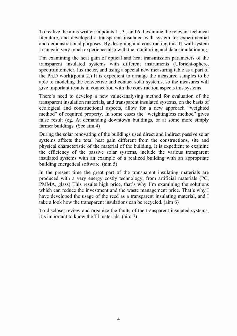
The finished transparent insulated (TI) wall construction is a part of the integrated solar system, etabilished at the SZIU, Department of Physic and Process Control. The two, apiece 1462x2256 mm glassed TI sandwich construction modules are situated on the terrace of the Department, on the west oriented wall. The existing wall is made of brief brick (45 cm thick), plastered on both sides. The total wall thickness is 51 cm. Beyond the TI modules the outer plastered smooth surface was painted black to get an absorber surface. The frame construction of the transparent insulation is made of KÖMMERLING type, hard PVC profiles, enhanced with heat-bridge free steel framework. Between the exterior (6 mm thick) and the inner (4 mm thick) glazing a 100 mm thick honeycomb structured (AREL type) polycarbonate transparent insulations has been placed, attached to the inner glazing. In front of the TI structure there is 40 mm air gap. The air gap between the inner glazing and the absorber layer helps the vapor pressure to be equal and reduce the heat expansion. (Fig. 1.)
Fig. 1. Plan and West elevation of the transparent insulated wall
6
A textile blind for shading was used on the exterior side of the structure, to avoid the overheating of the construction in summer. Later in the 40 mm thick air gap of the glassed construction an automatic electronic tubemotor controlled shading textile or screen can be placed. To measure the heat flux through the wall and the wall’s temperature sensors were mounted to the inner and the exterior side of the wall. The sensors were placed in the geometrical center of the examined surfaces. The heat flux sensors were mounted on the inner and exterior side of the daubed wall beside the panels, and in the center of the panels, placed in heat conducting paste, fixed on the edges.(4 heat flux sensors, AHLBORN 118 type).The temperature measuring is done by four platinum sensors (PT 100), these are situated next to the heat flux sensors. (See Thesis 1.) The sensor’s data is collected by ADAM-type data acquisition system, which transmits the collected data to the monitoring computer. This computer has direct acces to the data of the weather station too.
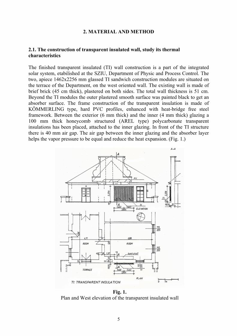
The monthly solar heat gains of the transparent insulated wall in the heating period of 2001/2002, 2002/2003, and 2003/2004 heating period demonstrate the Fig 2.
Fig. 2. The heat gain of the transparent insulated wall in three heating period (16. oct. - 15.
ápr.) in monthly breakdown (2001/2002: 58,929 kWh/m2, 2002/2003: 58,72 kWh/m2,2003/2004: 50,6 kWh/m2)
I have analysed the heat transmission through the wall surfaces with FLIR-E2 type infracamera too.
Constructing the block-oriented Matlab+Simulink model of the builded TI wall.
To the constructing of the block-oriented TI wall, I used a balance equation of the heat flow through the wall (Goetzberger-Wittwer, 1993)
))())(/(( STTUUUUq oiTITIwww

7
where:Wq heat flux through the wall construction [W/m2]
S amount of the absorbed global radiation of the wall [W/m2]( GS where : the light transmittance of the transparent insulation [-], : the absorption of the tansparent insulated wall [-],
G: amount of the global radiation [W/m2])
WU heat transfer coefficient of the wall [W/m2K]
TIU heat transfer coefficient of the transparent insulation [W/m2K]
iT indoor temperature [oC]
oT outdoor temperature [oC]
I have developed the block-oriented model of the TI wall based of thermal model connections.(Thesis 2.) In the simulation I used a “gray-box”-model based on the measured outside temperature and the global radiation. The heat-flux sensors were installed to show a negative value if the heat is flowing from outside of the wall to the room (in case of solare heat gain of the room).
2.2 Study of thermal and optical properties of TI material and sandwich construction
- Study thermal characteristic of TI materials with measuring table
I have developed a special measuring table which is suitable to measure thermal and optical characteristics of smaller (to 120 mm thickness) transparent insulated samples in different wavelength ranges and in different time intervals.(See Thesis 3.) The measuring table has two main parts: the desk’s plate which is divided to three parts, and the lamp bearer construction. (Fig. 3)
Fig. 3. Measuring table
In the compartment of the measuring table heat insulating underplates can be found. In the centre of the heat insulating plates there are placed the temperature sensors (Ni-Cr-

8
Ni, Therm 2220-12 type) into a heat insulation. The samples are lighted by artificial light sources with known intensity over the desk (Tungsraflex R63 (60W), and Infrarubin bulb (250W)). The distance of the light sources can be variated vertically with the holding construction.(See Thesis 3) In the temperature data measuring and acquisition system (which is now under construction) the temperature measuring is solved by an LM 335 type IC sensor with an accurancy of 0,1 oC. With regard to tutorial and demonstrational purposes, the temperature data is shown on a 3 digit display, with one second refreshing. With a wiew to following analyse the measured data will be stored. The data acquisitation is with an special to measuring table developed autonomous data acquisition system solved. If the temperature has to be displayed in real time, a computer can be connected to the device.
Measuring the light transmittance of the TH materials
Light transmittance measuring with Ulbricht-sphere: The used measuring device can be found at the Hannover University (Institut für Technik in Gartenbau). The sphere’s diameter is 1 meter. It’s inner surface is painted white. The light intensity is measured by a photo electronic cell, which is situated on the sphere’s upper edge. The direct light radiation is made by a beam of rotable searchlight with horizontal axle. The zenith distance can be changed by 10 degrees. The internal surface oflamp is painted black. The light source is a 150W halogen bulb. With the built-in lens can be almost parallel light beams produced. The searchlight’s axle situated over a rounded and rotable desk, which diameter is 1,4 m. On the centre of the desk a quadratic aperture can be found. I have examined the sample’s light transmittance with different tight frames. The diffuse light radiation is made by an half sphere, which diameter is 4 m. It is painted white on the internal surface, which reflects the light without making shadow. The light wreath consist of six fluorescent lamp pairs (THLW 86, TLF 65 W34). The laboratory and every building-element - except the half sphere - is painted black. With the Ulbricht-sphere I have found relationships between the honeycomb, and capillary structured sample’s material structure and the maximum of light transmittance of different TI materials by varying bound-angle of incidence, in case of direct lighting (Thesis 4.)
Light transmittance measuring with SHIMADZU UV-120-02 type spectrophotometer: I have measured the light transmittance of different thick, different layer numbered and some recycled transparent insulation material in 200 – 1000 nm wavelength with the SHIMADZU UV-120-02 type spectrophotometer at the Department of Chemistry of Szent István University Gödöll . Before starting the measuring I have zeroed the instrument with the potentiometer, then I have placed the foil samples into the glass holder. The glass samples were place into the instrument without holder. On the instrument the transmittance could be read instantly.

9
Light transmittance measuring with Spektromom 401 spectrophotometer:I have made a comparative measurement with the colorized and particular architectural glasses and foils, and with debris materials in bulk. I used the Spektromom 401 type spectrophotometer, at the BMGE University, Department of Building Materials. The used wavelengths were: 400, 430, 480, 520, 540, 570, 620, 670 nm. Before starting the measurement I have placed in the appropriate color filter in the light beam, then I zeroed the instrument with an null-redding potentiometer. After it, I have placed the samples into the glass holder (the glass samples without holder), and made the light transmission measurement. I have found relationships between the different flat and pattern, colourless and coloured samples. (See Thesis 5.)
Light transmittance measuring with Lux-meter: The artificial light source was Tungsraflex R63 bulb, and the sample was placed on the measuring table, which is described before. The distance between the sample and the light source was 30cm. I measured the light-transmittance of the different thick TI materials with the Lux-meter.
2.3 The ecological evaluation of Transparent Insulated systems:
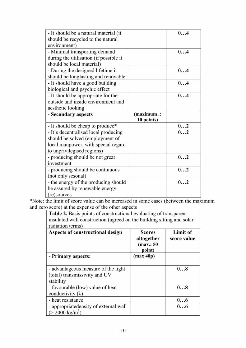
By the me proposed ecological-constructional index gives direct information in connection with ecological suitability of designed construction. (The description of the evaluating method is connected with 6. Thesis). The primary and secondary aspects which served as basis of ecological evaluating of transparent insulated solar systems can be found in the Table 2.
Table 1. Basis points of ecological evaluation of transparent insulated wall construction
Ecological aspects Scoresaltogether (max.: 50
point)
Limit of score value
- Primary aspects: (max.:40p)
- The used base and structural materials should have low energy demand during their life cycle (production, building up, demolition)
0…8
- Don’t issue deleterious environmental pollution during the production of it’s row materials (waste and emission)
0…8
- It’s row and auxiliary materials as well as construction should be recycled
0…4
10
- It should be a natural material (it should be recycled to the natural environment)
0…4
- Minimal transporting demand during the utilisation (if possible it should be local material)
0…4
- During the designed lifetime it should be longlasting and renovable
0…4
- It should have a good building biological and psychic effect
0…4
- It should be appropriate for the outside and inside environment and aesthetic looking
0…4
- Secondary aspects (maximum .: 10 points)
- It should be cheap to produce* 0…2 - It’s decentralised local producing should be solved (employment of local manpower, with special regard to unprivilegised regions)
0…2
- producing should be not great investment
0…2
- producing should be continuous (not only sesonal)
0…2
- the energy of the producing should be assured by renewable energy (re)sources
0…2
*Note: the limit of score value can be increased in some cases (between the maximum and zero score) at the expense of the other aspects
Table 2. Basis points of constructional evaluating of transparent insulated wall construction (agreed on the building sitting and solar radiation terms) Aspects of constructional design Scores
altogether (max.: 50
point)
Limit of score value
- Primary aspects: (max 40p)
- advantageous measure of the light (total) transmissivity and UV stability
0…8
- favourable (low) value of heat conductivity ( )
0…8
- heat resistance 0…6 - appropriatedensity of external wall (> 2000 kg/m3)
0…6

11
- thickness of external wall 0…3 - heat insulation of frame and leaf construction
0…3
- material and color of the absorber surface
0…3
- Self controlling of the heat insulation material (protect from overheating)
0…3
- Secondary aspects (max. 10p) - The transparent heat insulation elements could be integrated into ordinary (opaque) systems*
0…2
- possibility of prefabrication (prefabricated infactory)
0…2
- additional controlled shading construction could be integrated
0…2
- producing and serviceing should a few skilled work demand (so it’s suitable for „home-made” execution)
0…2
- it should retain the working intensive, hand made-style local building tradition.
0…2
**Note: the limit of score value can be increased in some cases (between the maximum and zero score) at the expense of the other aspects
2.4 Construction of the new reed solar walls
My aim was with the developing of the different construction devices, to examine the possibilities of the reed as a local, environmental friendly building material, on the field of the “semi transparent” TI constructions.
Laboratory examination of the reed solar wall samples: I have prepared two samples for the measuring: Sample No.1.: Glassed on both sides (with 5mm plate-glass) transparent reed solar wall module, with 5cm thick reed material, Sample No2.: One side glassed (with 5mm plate-glass), on the other side is covered with non transparent (opaque) laminated plate, with 5cm thick reed material.
Between the reed TH material and the plate-glass there was a 15 mm thick air gap. The measuring of thermal properties of the reed solar wall samples were measured at EMI Kht in Budapest, with a Holometrix-Rapid-K RK-80a type instrument. Based on the measurements the following result can be decide:
Based the heat conducting resistance of the samples, quantify the thermal conductivity factor of the capillary structured reed’s sample ( = 0,122…0,134), compared with the similary capillary structured PC’s sample (about = 0,1) the absolute value of the difference is 0,022...0,034 which is in practice not significant. At those material types -
12
which material structure are very different - the thermal resistance depends on the structure.- Of the two reed samples the sample No.2’s heat conducting resistance (R2=0,6174W/mK) is better than No.1 (R1=0,5676W/mK)
Construction of the experimental reed solar wall After the laboratory measurements, my aim was to build a reed solar wall with real dimensions and constructions. For the quick local mounting the reed wall was built up from three modules. I have used transparent and opaque modules also. To the construction of the reed-solar wall the original frame (with heat-bridge free, glassed thermosetting PVC profiles) was for the transparent insulated wall used. The original PC transparent insulating material was changed for a new solar reed TI modules. The glass pane on the back side was removed from the original wall, because in the transparent solar reed system there was glazing, in the opaque solar reed system there was plated with laminate on the back side of the moduls. Between the back side of the modules and the absorber’s surface the 1cm thick heat-, and humidity-pressure equaliser air gap is remained by the help of distance elements. Based on the measurements of the phisycal characteristic and monitoring of the tested reed-wall the new scientific results can be found in Thesis 7.
2.5 Analysis the energetical renovation of an existent family house with passive solar systems
The energetical parameters of the existent original, and the renovated house (in the I. and II. phase of the solare renovation) were determined by using the ISOVER software, which uses the algorithm of the 6B REHAB building energetical software.
In the first phase of the renovating I have examined the result of different constructional changes one-by one, and after it I have determined the energetical characteristic value of all changes compared to of existing originally buildings.
- Particularly with the post heat insulation the original heating demand can be reduced to 83,8%, and so the resultant heat conducting factor to 83,3%, by unchanged solar gain. It demonstrates the importantce and efficiency the (opaque) post heat insulating systems. - Applying new windows with better thermal insulating properties, the solar gain can be enhanced by 7,4%, but this results the heating expenses reducing only with 0,3%. At the same time, the resultant heat transfer factor will reduce with 4,2%, because of the enlarged glass surfaces. - By adding a sunspace to the house, the useful solar gain will raise significantly with 10,33%, but with this system the building’s heating energy demand will reduce only with 0,24%. Similar to the previous variant the resultant heat transmission factor enhanced with 5%. (See Fig. 4a, 4b)

13
a
b
Fig. 4. Solar renovating of an existing family house
a)West façade with an sunspace b)South-East façade with transparent insulation
In sum of the I. phase of the solar renovation it can be said, that the highest heating energy saving by the efficient solar energy gain can be achieved only through common employing of different passive solar systems, with required planed external thermal insulation.
In the II. phase I have examined the thermal effects of the 47 m2 transparent insulated surface, on the building’s South-East façade.(Fig 4b). In the construction I have used different TI materials (with different light transmittance, thickness, heat conductivity

14
resistance) between the two 5mm thick glass layers. The aim was to estimate how the different materials affects influence on the building’s energy balance, assuming that the first phase of the renovating has been established.
The heating demand can be reduced by using the each examined TI constrictions, compared to the I. phase, depend on their structure. The best TI materials, has the highest construction thickness, and highest light transmissivity and thermal conductivity resistance values, furthermore the aerogels with low thickness, but high light transmittance and thermal conductivity resistance. At the other materials the building heating demand and the average heat conductivity resistance factor are approximately consistent with together. This last result is important especially at the reed solar wall, in spite of it’s material characteristic are differing from the “ordinary” TH materials, the difference of the usable solar energy gain is smaller only 1..9%, and the heat demand saving is also just only with 3..10 % smaller according to the best 10 cm thick PMMA and PC materials.(Fig. 5)
Fig. 5 The energetical characteristic of the renovated building, using transparent insulation
Annual solar energy gains on the TI wall, and on the TI insulated building after the solar renovating.
15
3. NEW SCIENTIFIC RESULTS
There were no Hungarian publications and measuring data available about the comprehensive introduction in connection with the (today only abroad produced) TI materials and constructions, and long-time monitoring and simulation of realized transparent insulated systems. For the new building energy regulations, which will be introduced in 2006, the first Hungarian experiences on the field of this special type of passive solare systems can be important supplement.
1) During my PhD work I have developed a transparent insulated wall for experimental and demonstrational purposes. It is suitable examining the thermal characteristic of different transparent insulation materials during longer thermal monitoring. It’s a part of the Integrated Solar Utilizer System, which is realised at the SZIU, Department of Physics and Process Control. (See Chapter 3.1.1. of PhD thesis) By the lifting of the exterior sash of the glassed TI construction there original transparent insulating material can be easily changed to another examined material. I have placed heat flux and thermometers not only on the center of the inner wall but of the exterior wall surface, to measure the heat gain of the wall. By this way the thermal characteristic of the absorber’s surface can be monitored.
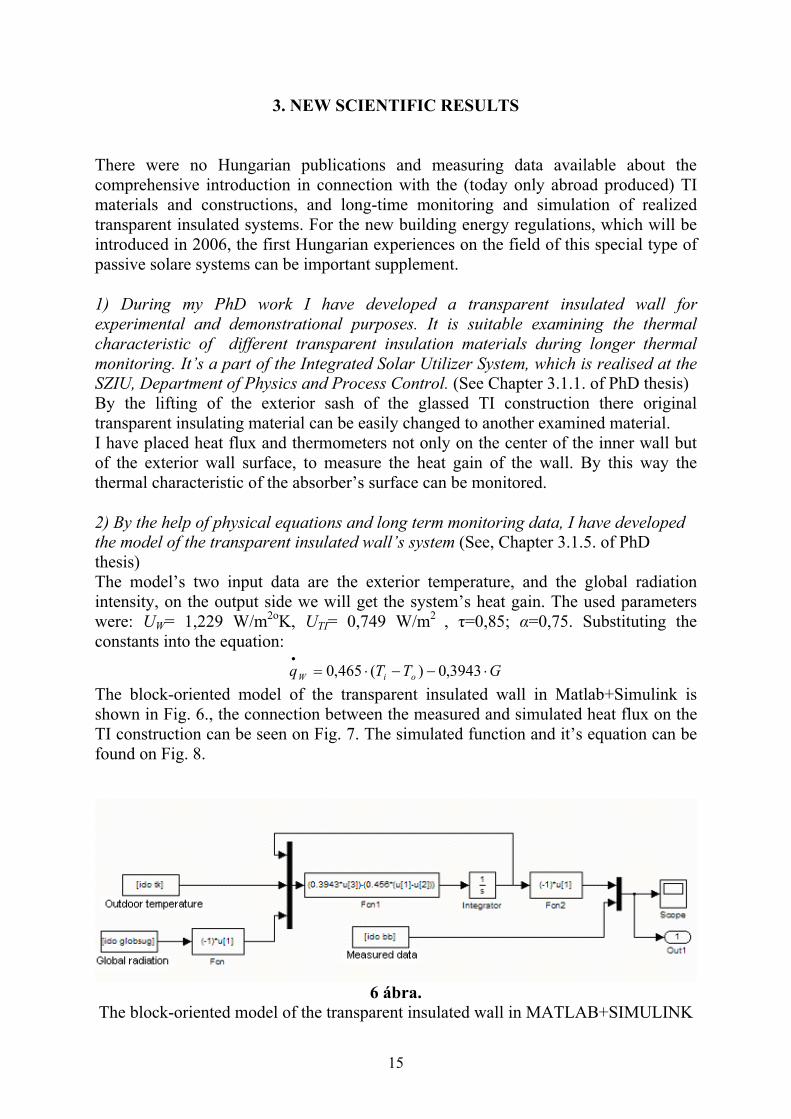
2) By the help of physical equations and long term monitoring data, I have developed the model of the transparent insulated wall’s system (See, Chapter 3.1.5. of PhD thesis)The model’s two input data are the exterior temperature, and the global radiation intensity, on the output side we will get the system’s heat gain. The used parameters were: UW= 1,229 W/m2oK, UTI= 0,749 W/m2 , =0,85; =0,75. Substituting the constants into the equation:
GTTq oiW 3943,0)(465,0
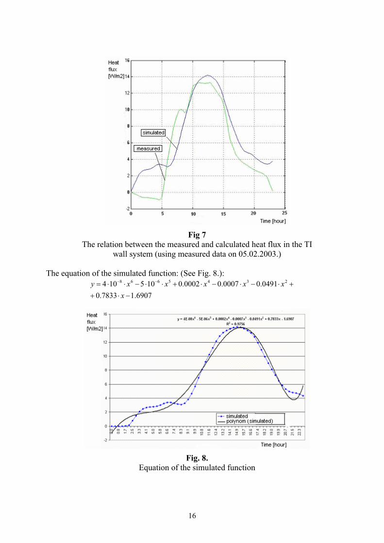
The block-oriented model of the transparent insulated wall in Matlab+Simulink is shown in Fig. 6., the connection between the measured and simulated heat flux on the TI construction can be seen on Fig. 7. The simulated function and it’s equation can be found on Fig. 8.
6 ábra. The block-oriented model of the transparent insulated wall in MATLAB+SIMULINK
16
Fig 7 The relation between the measured and calculated heat flux in the TI
wall system (using measured data on 05.02.2003.)
The equation of the simulated function: (See Fig. 8.):
6907.17833.0
0491.00007.00002.0105104 2345668
xxxxxxy
Fig. 8. Equation of the simulated function

17
3 )I have developed a special measuring table, which is suitable to examine smaller transparent insulated material samples, at different wavelengths and time intervals. (See, Chapter 3.2. of PhD thesis) By examining the heat transfer of the modeled construction (the honeycomb structured 4 and 10cm thick PC transparent insulation samples) of contact solar walls, I have determined that depending on the material structure and the intensity of the light beam, the temperature rises on the inner surface and can achieve 39..70%, while in case of exterior side glazing it’s 81…97% of the non-insulated wall. In case of both sided glazing it is 70…92%. Between the used 1…10cm thick TI samples with a black painted 0,5mm thick absorber plain, which are modeling the convective solar walls systems, the best was the 4cm thick sample, from the point of view of it’s heat transmitting factor.
4) I have determined connections between the honeycomb and the capillary structured transparent insulation’s material structure and the local maximum of the different light angle’s incidence at direct lighting.(See: Chapter: 3.3.1 of PhD thesis) In case of transparent insulated constructions I propose the considering weightinglessinto consideration. I have determined that in case of structures which are perpendicular to the surface, the most efficient if the incoming light beam can pass the TH material without reflexion. It can be determined an optimal bound angle that depends on the geometrical parameters of the structure. Below this angle ( ) the light transmittance is maximal. This angle range can be defined also in those cases when the cell structure is parallel with the surface. (See: Fig 9.)
Fig. 9.
Light transmittance depends on the angle of the light beam, and the geometrical properties of the structures, in honeycomb and capillary
structures
Calculating the bound angle at honeycomb or capillary structures if the geometrical properties are known :
)/( baarctg

18
where: bound angle (the angle of the incident light beam and the normal
of the sample’s plain surface) a in case of honeycomb structure the side length of the crossed
cell’s, in case of capillary structure, the diameter of the capillary [mm]
b thickness of the TH material [mm]
Calculating the bound angle is very important during the right placement of the semi-transparent (glassed reed solar wall) materials, considering that the solar efficiency depends on the degree of the light transmissivity of the single (from the side opaque) fibres. In this case it can be to raise the solar gain partly by varying the angle of plane of the solar module according to solar radiation, partly in case of vertical surface and given orientation, the angle of the reed filaments can be changed compared to reed modul surface.
5) I have determined connection between the light transmittance of flat and pattern, coloured and colourless sheet-glasses. (See, Chapter 3.3.2. of PhD thesis)
The main point of the method is, that by measuring on the basis of the light transmittance one layer of the non-colorized glasses, the other layer’s light transmittance can be well estimated with a proportional factor between 0 and 1, in the visible light range. At the colorized glasses this method should be modified by taking two ranges (400..520 nm, and 540…670nm) and define a proportional factor to each range, because of the effects of the complementary colors. I have examined the light transparency of different chopped, bulked material to determinate if they are suitable (has enough transparency) to use them as a recycled material (in the form of debris or chopped material). According to measurements this kind of use come for the capillary structures (PMMA and glass) up, where the optimal granule’s diameter is 2..3 mm. At the other (recycled) samples has low light transmittance, so these are not enough suitable for use them. These materials, which low light transmittance not equal - to previous point of view – can be used in the production as raw material, or in the manufacturing for ordinary (opaque) insulations, as duvet’s of filler material.
6) I have developed a new method of theory of value to ecological evaluation the transparent insulation materials, it helps the design and construction of transparent insulated systems and preparing for decision making (See, Chapter 3.4.1. of PhD thesis)In case of valuation of transparent insulated constructions, I suggest instead of weightingless consideration and averaging of enumerated propertys – according to practical aspects – the task- and object oriented previous hierarchy of ecological aspects (e.g. with division one’s basis-points), after it the use of quality weighting multiplying factors, depend of the functions of constructional form.
19
The advantage of this method the ecological aspects can be considered without weighting – as starting point – (by making the base scores equal), but also possible to compare the functional conformance and the quality of the mechanical constructionrather.The base score is 50 points both at the ecological and constructional view, so the valuation can be separate and together easily survay. I propose the weighting of certain ecological aspects in accordance with their priority following:
By reason of the scores of Table1 and Table 2.:
ÖSZ=a*Ö+b*Sz
where:ÖSZ: Scores of ecological-constructional aspects (max 100 scores) Ö: Scores of ecological aspects (max 50 scores) SZ: Scores of constructional design aspects (max 50 scores) a,b: quality weighting factors (0..1 rational number)
Score ranges, and categories: 0-40: unsuitable to use, environmental polluting; 41-50: use as wall construction can be only exceptionally, provisionally, for
subordinated functions; 51-60: prepare other design conception recommended 61-70: the use is debateable 71-80: good, it can be used according to aims 81-100: over the ecological aspects, special solution (e.g. it presents aesthetical experience, or offer special building-biological advantages).
7) I have developed new constructional solution on the field of “semi-transparent” TI materials: for the use of the reed as a local building material. To determinate the basic technical usage conditions I have made thermo-physic measurements, and built and measured a real sized solar reed wall.(See: Chapter: 3.5. of PhD thesis) There is only one type of the semi transparent solar systems is known before, the corrugated cardboard. It’s produced by the Gap-Solar, this product is handled with flame-proofing and fungus protected materials. The layers are glued together, and the structures are perpendicular to the surface. In my PhD thesis I made an attempt to the use of the reed, as a local natural material in this new technology. The reed’s advantage is that it can be chopped to 5…10 cm pieces very well up, the light transmittance of the cutted pieces can be significantly improve by a survey classification.(Opaque reed solar wall can be also made by them, there is no need to select.) The reed can be easily built-in, it’s flame-proofing is much more better than the ordinary (PC, PMMA) transparent materials, it’s thermal insulation value is almost the same, but heat capacity is greater as it’s. The reed able to control the vapour amount of the structure. As a local material in the country, it is cheap (Sheaves, which length are not suitable for roofing, are also can be used).

20
The reed’s disadvantage is that it’s sensible to too much water, but this problem occures at other transparent insulations too. There were two modules developed during the reed solar wall’s examination: - The non transparent (opaque) module: one side glassed, on the other side it’s covered with laminated plate, - The size, the frame construction and the material and thick of the reed insulation of the transparent moduls are consistent with the opaque modul, but it’s other side is a 5 mm thick plate-glass. In this case I had to avoid the contact between the screws and the glass. I used heat proof rubber and plastic strips. Between the glass plane and the fixings 2 mm heat expansion is allowed.
7.1) Comparing the transparent (PC) and opaque (reed) TI construction’s monitored results, it can be determined that the on the absorber-surface measured heat-flux value of the reed solar and the PC TI wall are very different, depending on the weather conditions (sunlight, exterior temperature of the air, cloudy sky).: - On a bright, sunny day the opaque reed solar wall produces only the 62…65% of the transparent reed-solar wall’s solar energy gain. The transparent reed solar wall produces approximately the 20 % energy gain of the PC TI wall, while the opaque is 12%.- In a cooler period, under an overcast sky the reed solar wall’s performance is 50%, while the non transparent reed solar wall’s is 30% of the PC wall The inner heat gains are depends on the length of the cooler period, and mass of the wall. To examine this, longer measurements will be done in the winter periods too.
7.2) While in the direct, sunlight free period the temperature of the two module’s exterior glassing is almost the same, by at the afternoon, in the direct sunlight period, the temperature of the exterior glassing of the transparent module with glazed backside is only 60-80 % of the non transparent (opaque) module. The reason is that the energy in the opaque module is absorbed only in the material of the module, while at the transparent version, 15…30% of the light is absorbed on the black painted wall’s absorber-surface. In that way, the material of the module and the covered glass construction will be protected from a significant heat load. In other words: the glazed transparent reed solar wall’s heat loss is less with 20-40% than the opaque modul.
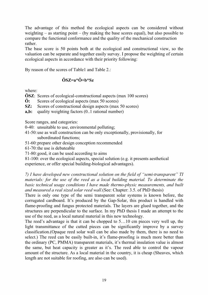
During the constructing of the light transparent modul, I had no possibility to select the reed pieces, so I choosed randomly, the 5 cm length reed pieces. Because of these reasons the module’s light transmittance is lower then on the measured sample (with the same length). Therefore the light transmittance of the reed solar wall module (20%) less, that in the Fig (?) showed measured value (48%). This means, that the efficiency of the reed solar wall can be considerably raise by using of selected reed material in comparison with monitored sample.
The light transmittance of the 3; 4; 5; 6, 7; 8, 9; and 10 cm thick, at full length light transmitted reed samples were measured by a lux meter. (See Fig.10.)
21
Fig. 10. Measured light transmittance of the 3; 4; 5; 6; 7; 8; 9; and 10 cm thick reed layer, in case of perpendicular and direct lighting (using selected,
light transmitting filaments)
7.3) It is very important that before the reed is built-in into the frame it has to be accordingly dry, so it has to be stored in a roofed, from the side opened, good through ventilated space. The moisture equilibrium of the air dry state reed samples were measured in a dewatering box of the Department of Agrochemistry at the SZIE University Gödöll . The measured amount was 6,62%. Because of this relatively high moisture content, it’s very important to safe conduct of the vapour from the reed-solarwall TI material especially in the warming up periods. It can be solved by vent hole with 5..10 mm diameter, next from the sides of the frame, connecting the air gap between the glass-plate and the reed TI material with the outer air space, without draught-effect.
7.4) The exterior glass-plate gives enough protection in defence of the rainfall, supposed the connected frame construction protected against the strike-rain, powdery snow and in the frame construction infiltrated moisture. The rain-protection is certained with rubber-profiles on the edges of the glass-plates and two opening for outconducting for moisture on the bottom of the frames.
7.5) The fire protection measurement details of the air-dry reed samples can be found in the ÉMI’s research report, No: M-203/2005. (See in appendix M4). The results of the examinations showed that the fire proof qualities of the reed samples are better than the ordinary PC and PMMA materials: -Burning temperature for the air-dry reed woof is 347oC ,according to the MSZ 14800-16:1992, 8.1,point, B method. -According of the 3. § of National Regulations of Protection against fire, the reed woof is signed “D”, as a “Moderately incendiary” material, based it’s fire burning point.

22
7.6) During the using of the light transmitting TI module’s it’s indispensable reasoned to separate the chopped, light transmitting reed pieces with given length. The raising of the light transparency is usually more than 50..60%, using 3…10 cm thick samples, supposed random select of the reed pieces. By the use of opaque solar reed modules, it’s not necessary to select the reed pieces, because it doesn’t considerably effect the panel’s efficiency. (See: Fig. 11.)
7.7.) Knowing and considering the solar orbit data, it is possible to raise the efficiency of the reed solar TI modules, through the adequate determination of the optimum of the angle between the direction of the reed filaments and the wall (or modul) surface, to get the maximum collection of direct sunlight. Using this method the yearly energy gain of the modul can be raised by 10..12% compared to the absorber surface perpendicular type modul-material.
a
b c
Fig. 11. Transparent insulated walls, SZIU, Gödöll
a) Semi transparent reed solar wall and polycarbonate TI wall b) Reed solar wall’s structure (without selecting), c) PC based
honeycomb TI structure

23
5. PUBLICATIONS IN CONNECTION WITH THE PHD THESIS
Periodical published contributions in Hungarian language: 1. Farkas I. - Bíró A. - Buzás J. - Hegyi K. -Lágymányosi A. - Seres E. E. - Sz cs
M.: Oktatási és demonstrációs célú napenergia hasznosító berendezések. In: Magyar Energetika, 1998., VI. évf. 3. sz., p. 17-24.
2. Sz cs M.: Passzív napenergia-hasznosítás, Beszámoló a Falufejlesztési Társaság építész tagozatának III. Országos Vándorgy lésér l, Nagykovácsi, 2000. Január 21-22. In: Falu Város Régió, 2000., X. évf. 4. sz., p. 17-21.
3. Sz cs M.: Passzív napenergia-hasznosítás. In: Országépít , 2000., XI. évf. 1.-2. sz.., p. 18-20.
4. Sz cs M.: Transzparens h szigetelések. H nyereség kevesebb h veszteséggel, In: Alaprajz, 2000., VII. évf. 2. sz., p.44--47.
5. Sz cs M.: Alacsony energiafelhasználású lakóépületek. In: F téstechnika,megújuló energiaforrások, 2002., V. évf. 78. sz., p. 25-32.
6. Sz cs M.: Földfalak ma. Új módszerek és energiatakarékos szerkezeti megoldások a földfalak építésében. In: Építész Spektrum. Épületek és szerkezeteik. 2002., I. évf. 4. sz., p.38-41.
7. Fülöp L. – Sz cs M. – Zöld A.: A napenergia passzív hasznosításának hazai potenciálja. In: Energiagazdálkodás, 2005., 46. évf. 1.sz., p. 8-13.
8. Sz cs M.: Föld- és vályogfalú házak építésének lehet ségei Magyarországon. Épületenergetikai követelmények, sajátos energetikai anyagjellemz k. In: Épít világ. 2005. XLVI. évf. 3. sz., p. 21-25.
9. Sz cs M.: Transzparens h szigetelések. In: Építés Spektrum. Épületek és szerkezeteik, IV. évf. 2005.5. sz. p. 18-22.
Conference proceedings in Hungarian language 1. Sz cs M.:- Farkas I.: Transzparens szigetelés falak termikus jellemz inek
meghatározása. MTA Agrár-M szaki Bizottság, Kutatási és Fejlesztési Tanácskozás, Gödöll , 1997. jan. 21-22, p. 29-30.
2. Sz cs M. - D. Kohlmeier: Transzparens h szigetel anyagok fényáteresztésének vizsgálata. MTA Agrár-M szaki Bizottság, Kutatási és Fejlesztési Tanácskozás, Gödöll , 1998. jan. 20-21, p. 41.
3. Sz cs M.: Passzív szolár f tési rendszerek a vidék építészetében, MTA Agrár-M szaki Bizottság Kutatási és Fejlesztési Tanácskozás, Gödöll , 1999. jan. 19-20, p. 47.
4. Sz cs M.: Napenergia hasznosító eszközök a mez gazdaságban, MTA Agrár-M szaki Bizottság, Kutatási és Fejlesztési Tanácskozás, Gödöll , 1999. jan. 19-20, p. 49.
5. Farkas I. – Seres E.E.- Lágymányosi A. – Buzás J. - Sz cs M.:Folyamatirányítási célú laboratóriumi modellek, MTA Agrár-M szakiBizottság Kutatási és Fejlesztési Tanácskozás, Gödöll , 1999. jan. 19-20, p. 56.
6. Sz cs M.: A szoláris-bioklimatikus építészet fogalma, f bb jellemz i,„Korszer technológiák alkalmazása a megújuló energiák hasznosításában, különös tekintettel az agrárszférára. Az állami támogatások lehet ségei” konferencia. Gazdasági Tudományos Társaság, Energiagazdálkodási Tudományos Egyesület, Budapest, 1999. május 14. p. 77-81.
24
7. Sz cs M.: Transzparens h szigetelések építészeti alkalmazásának lehet ségei. MTA Agrár-M szaki Bizottság, Kutatási és Fejlesztési Tanácskozás, Gödöll ,2000. jan. 18-19, p. 46.
8. Sz cs M. - Lágymányosi A. - Farkas I.: Transzparens h szigetel anyagok termikus és optikai jellemz inek összehasonlító mérései, MTA Agrár-M szakiBizottság, XXV. Kutatási és Fejlesztési Tanácskozás, Gödöll , 2001. jan. 23-24. p. 36.
9. Sz cs M.: Lakóépületek energiatudatos tervezésének új módszerei. MTA Agrár-M szaki Bizottság, XXVII. Kutatási és Fejlesztési Tanácskozás, Gödöll , 2003. jan. 21-22. p. 64.
Periodical published contributions in foreign language:
1. Sz cs M. – Farkas I.: Optical characteristics of transparent insulation materials. Hungarian Agricultural Engineering, 2001/14. p. 77. – 79.
Conference proceedings in foreign language:
1. Farkas I., Jesch L. F., Sz cs M.: Construction aspects of transparent insulation wall for demonstration purposes, EuroSun'96, 10. Internationales Sonnenforum, Freiburg, 1996. szept. 16-19, p. XVIII. 40-41.
2. Sz cs M.: Transparent insulation walls, 2.nd Seminar on Energy and Environment, GATE Fizika és Folyamatirányítási Tanszék, Gödöll , 1996. szept. 3-6, p. 13.
3. Sz cs M.: Transparent insulation Technology in the Passive solar Architecture, CERECO'97, The 2nd International Conference on Carpathian Euroregion, Miskolc-Lillafüred, 1997. jún. 1-4, p. 56.
4. Sz cs M.: Passive solar energy utilisation in the rural architecture, 3.rd Seminar on Energy and Environment, GATE, Fizika és Folyamatirányítási Tanszék, Gödöll ,1997. nov. 10-12, p. 12
5. Farkas I. - Sz cs M. - Zöld A. : Monitoring of a Transparent Insulation Wall Used for Demonstration Purposes, EuroSun98, The second ISES-Europe Solar Congress, Portoroz, Slovenia, 1998. szept. 14-17, p. VI. 2.
6. Sz cs M.: Passive solar heating in building renovation, 4.th Seminar on Energy and Environment, GATE, Fizika és Folyamatirányítási Tanszék, Gödöll ,1998.nov.11-13.
7. Sz cs M.: Heizenergieeinsparung durch Wände mit Transparenten Wärmedämm-verbundsystemen (TWDVS), 5.th Seminar on Energy and Environment, GATE, Fizika és Folyamatirányítási Tanszék, Gödöll ,1999. nov. 3-5.
8. Sz cs M.: Construction aspects of transparently insulated solar walls. 6 th Workshop on Energy and Environment, SZIE, Fizika és Folyamatirányítási Tanszék, Gödöll , 2000. oktober 9-10.
9. Sz cs M. – Farkas I.: Constructional issues of transparently insulated walls. Research and teaching at Departments of Physics in the Context of University Education.. Slovak Agricultural University in Nitra. International Scientific Conference, Nitra 26 th January 2001.
25
10. Sz cs M. – Ruda Gy.: Environment friendly and energy saving animal buildings. Anbalysis of present day state and prognosis of development technique in farm animal breeding until 2006 under the conditions of the slovak and Hungarian Republic. Slovak Agricultural University in Nitra, Nitra 26 th October 2001. p. 31. – 38.
Study and lecture notes:
1. Sz cs M.: Reischl G. – Sz cs M.: A gazdálkodás építészete. Szaktanácsadási Füzetek 4. szám, Gödöll i Agrártudományi Egyetem, Vidékfejlesztési és Szaktanácsadási Központ, 1997.
2. Sz cs M.: A föld és a fa a környezetbarát építésben. Épített Környezetért Alapítvány, Budapest, 1999., TEMPUS Joint European Project IB 14276/99.
3. Sz cs M.: Szoláris bioklimatikus építészet. A napenergia építészeti hasznosítása, Oktatási segédlet és gyakorlati útmutató. UNESCO WSSP Magyar Részvételi Program 2000., Magyar Napenergia Társaság, Budapest, 2000.
4. Barótfi I. - Ónódi G. – Medgyaszay P: -Kazi J.- Sz cs M.: Energia és térrendezés Bács-Kiskun megyében. Független Ökológiai Központ, Budapest, 2001. p. 159.- 189.
Books, and passages in a books:
1. Sz cs M.: Föld- és vályogfalak építése. Építésügyi Tájékoztatási Központ Kft. Budapest, 1996. p1. – 133.
2. Sz cs M.: Föld- és vályogfalú házak építése és felújítása. Építésügyi Tájékoztatási Központ Kft. Budapest, 2002. (11. fejezet: H szigetelések, passzív szoláris rendszerek, alacsony energiaigény épület-koncepciók.).p.1.-185.
3. Sz cs M.: Passzív napenergia-hasznosítás a mez gazdasági építészetben. In: Napenergia a mez gazdaságban. Szerk.: Farkas I. Budapest: Mez gazda Kiadó, 2003. p.207. – 240.).
4. Sz cs M.: Az alternatív baromfitartás épített környezete. Az alternatív állattartás épületei. In: Alternatív baromfitenyésztés és tartás. Szerk.:Szalay I. Budapest: Mez gazda Kiadó, 2004. p.61. – 68.
5. Sz cs M.: 3. Az ökológiai szemlélet termék-el állítás termelési feltételei. 3.1. Épületek. In: Ökológiai szemlélet állatitermék-el álllítás. Szerk.:Radics L. – Seregi J. Budapest: Szaktudás Kiadó Ház, 2005. p. 147.- 175.
6. Sz cs M.: Homlokzati falak transzparens h szigetelése. In: Épületszigetlési Kézikönyv. Szerk.: Fülöp Zs. – Osztroluczky M. Budapest: Verlag Dashöfer, 2005. p.
Scientific and popular-science lectures:
1. Sz cs M.: Energiesparende Planung und Anwendung von natürlichen Baustoffen, Seminar Umweltphysik, Universität für Bodenkultur Wien, Institut für Meteorologie und Physik, Wien, 1996. máj. 22-24.
2. Sz cs M.: Transparente Wärmedämmung in der Archtektur, Seminar Umweltphisik, Universität für Bodenkultur Wien, Institut für Meteorologie und Physik, Wien, 1997. máj.
26
3. Sz cs M.: Passzív napenergiahasznosítás az építészetben, "Öntevékeny Társadalmi mozgalom a Napenergiahasznosítás el segítésére" Gödöll iRegionális Központ tanácskozása, GATE Fizika és Folyamatirányítási Tanszék, Gödöll , 1997. máj.
7. Sz cs M.: Passzív napenergiahasznosítás a mez gazdasági építészetben, "A napenergia alkal-mazása a mez gazdaságban" c. tanácskozás keretében, GATE Fizika és Folyamatirányítási Tanszék és a GATE Vidékfejlesztési és Szaktanácsadási Központ rendezvénye, Gödöll , 1997
5. Sz cs M.: Passive solar architecture. Seminar Umweltpysik, Universität für Bodenkultur Wien, Institut für Meteorologie und Physik, Wien, 1998. máj. 25 -27.
6. Sz cs M.: Passzív napenergia hasznosítás az építészetben, El adás az Európai "Nap Napja" (SunDay) gödöll i rendezvényén, Gödöll , 1998. jún. 21.
7. Sz cs M. : Passzív napenergia felhasználás az építészetben, Országos Napenergia Hasznosítási Konferencia, Szakkiállítás és Ausztriai Tapasztalatcsere, el adás és konzultáció, Sopron, 1998. okt. 1-2.
8. .Sz cs M.: Application of solar energy in architecture, Seminar Umweltphysik, Universität für Bodenkultur Wien, Institut für Meteorologie und Physik, Wien, 1999. máj. 5-6.
9. Sz cs M.: A szoláris-bioklimatikus építészet fogalma, f bb jellemz i. El adás a „Korszer technológiák alkalmazása a megújuló energiák hasznosításában, különös tekintettel az agrárszférára. Az állami támogatások lehet ségei” c. konferencián. Gazdasági Tudományos Társaság, Energiagazdálkodási Tudományos Egyesület, Budapest, 1999. május 14. p. 77-81.
10. Sz cs M.: Passzív napenergia hasznosítás. El adás a Falufejlesztési Társaság Építész Tagozatának III. Országos Vándorgy lésén, Nagykovácsi, 2000.január.21-22.
11. Sz cs M.: Transzparens h szigetelés alkalmazása az építészetben, El adás a Szent István Nyári Egyetemi Napok keretében rendezett „Megújuló energiaforrások a lakosság és az agrárgazdaság szolgálatában” c. szakmai fórumon, Gödöll ,2000. augusztus 23-24.
12. Sz cs M.: A napenergia hasznosítása az építészetben. A Környezetvédelmi és Vízügyi Minisztérium és a Közép-Európai Egyetem (CEU) „Alternatív energiatermelési módok” konferencia-sorozata: „3. A napenergia hasznosítása” c. rendezvénye. Budapest, 2005. 09. 20.
Other publications:
1. Farkas I. - Bíró A. - Buzás J. - Lágymányosi A. - Seres E. E. - Seres I. - Sz cs M. : Aktív, termikus és fotovillamos napenergia hasznosító rendszerek demonstrálása, PHARE Megújuló Energia Projekt No. HU9103-07-01-L013, Részjelentés, 1996. december, p. 16 - 22.
2. Farkas I. - Bíró A. - Buzás J. - Lágymányosi A. - Seres E. E. - Seres I. - Sz cs M. : Aktív, termikus és fotovillamos napenergia hasznosító rendszerek monitorozása, PHARE Megújuló Energia Projekt No. HU9103-07-01-L013, Zárójelentés, 1997. december, p. 15 - 21.