t-200 user guide - phoenix geophysics ug … · authorized volvo penta service. . . . . . . . 113...
TRANSCRIPT

o
T-200 Current SourceUser Guide
Version 3.1 September 2009
• Software version 3111C1
PHOENIX GEOPHYSICS


T-200 Current SourceUser Guide
Version 3.1 September 2009
• Software version 3111C1
PHOENIX GEOPHYSICS

Printed in Canada on tear-resistant and water-resistant Xerox® Digital Synthetic Polyester Paper.
This User Guide was created in Adobe FrameMaker 7.0. Writing and Production: Stuart Rogers.
Copyright 2009 Phoenix Geophysics Limited.
All rights reserved. No part of this Guide may be reproduced or transmitted in any form or by any means electronic or mechanical, including photocopying, recording, or information storage and retrieval system, without permission in writing from the publisher. Address requests for permission to:
Phoenix Geophysics Limited, 3781 Victoria Park Avenue, Unit 3, Toronto, ON Canada M1W 3K5, or [email protected].
Information in this document is subject to change without notice.
T-200, TblEdit, and the Phoenix logo are trademarks of Phoenix Geophysics Limited. All other trademarks referred to are the property of their respective owners.

i Contents i
Contents
Chapter 1: Introduction . . . . . . . . . . . . . . . . . . . . . . . . . . . 1About the T-200 current source . . . . . . . . . . 2
Intended audience . . . . . . . . . . . . . . . . . . . . . . 2
How to use this guide . . . . . . . . . . . . . . . . . . . 3
How to get further information and support . . . . . . . . . . . . . . . . . . . . . . . . . . . . . . . . 4
Important safety information . . . . . . . . . . . . 4Safety features . . . . . . . . . . . . . . . . . . . . . . . . . . . . . 4Major safety concerns . . . . . . . . . . . . . . . . . . . . . . . . 5
Chapter 2: Preparing the T-200 for Field Use . . . . . . . . . 9Positioning the T-200 on a vehicle . . . . . . 10
Adding engine oil . . . . . . . . . . . . . . . . . . . . . . 11
Installing and connecting the batteries. . 14
Fueling the T-200 . . . . . . . . . . . . . . . . . . . . . . 16Connecting the fuel lines. . . . . . . . . . . . . . . . . . . . . . 16Preparing the external fuel supply . . . . . . . . . . . . . . . 17
Priming the fuel system . . . . . . . . . . . . . . . . 18
Priming the fuel line . . . . . . . . . . . . . . . . . . . . . . . . . .18Priming the fuel injectors . . . . . . . . . . . . . . . . . . . . . .19
Adding coolant to the engine cooling system . . . . . . . . . . . . . . . . . . . . . . . . . . . . . . . . .20Diluting the coolant . . . . . . . . . . . . . . . . . . . . . . . . . .20Adding the coolant . . . . . . . . . . . . . . . . . . . . . . . . . . .22

ii T-200 User Guide ii
Adding coolant to the transmitter cooling system . . . . . . . . . . . . . . . . . . . . . . . . . . . . . . . . 22Diluting the coolant . . . . . . . . . . . . . . . . . . . . . . . . . 23Adding the coolant . . . . . . . . . . . . . . . . . . . . . . . . . . 24
Grounding the chassis and high-voltage leak detector . . . . . . . . . . . . . . . . . . . . . . . . . . .25Grounding the chassis . . . . . . . . . . . . . . . . . . . . . . . .25Grounding the high-voltage leak detector . . . . . . . . . . .26
Connecting the high voltage cables . . . . . .27
Chapter 3: Starting the T-200 . . . . . . . . . . . . . . . . . . . . . . 31Using the T-200 Safely . . . . . . . . . . . . . . . . . 32Activating emergency stop . . . . . . . . . . . . . . . . . . . . 32
Preparing to start the T-200 . . . . . . . . . . . . 34Selecting the high voltage range . . . . . . . . . . . . . . . . 34Working in cold temperatures . . . . . . . . . . . . . . . . . . 35Preheating the engine coolant . . . . . . . . . . . . . . . . . . 36
Starting the transmitter controller . . . . . . .37Finding the controls . . . . . . . . . . . . . . . . . . . . . . . . . .37Connecting the remote controller. . . . . . . . . . . . . . . . .37Starting the transmitter controller . . . . . . . . . . . . . . . .37
Starting the engine . . . . . . . . . . . . . . . . . . . . .40

iii Contents iii
Chapter 4: Transmission Modes and Frequency Stepping . . . . . . . . . . . . . . . . . . . . . . . . . . . . . 43
Understanding the transmission modes . 44Frequency stepping schedules . . . . . . . . . . . . . . . . . . 44Phase . . . . . . . . . . . . . . . . . . . . . . . . . . . . . . . . . . . 44Frequency . . . . . . . . . . . . . . . . . . . . . . . . . . . . . . . . 45Automatic modes . . . . . . . . . . . . . . . . . . . . . . . . . . . 45
Using CompactFlash cards . . . . . . . . . . . . . . 50Types and quality of CF cards . . . . . . . . . . . . . . . . . . 51Use only CF cards supplied by Phoenix . . . . . . . . . . . . 51Formatting a CF card . . . . . . . . . . . . . . . . . . . . . . . . 52
Preparing files using TblEdit . . . . . . . . . . . . .53Overview . . . . . . . . . . . . . . . . . . . . . . . . . . . . . . . . .54Starting the program . . . . . . . . . . . . . . . . . . . . . . . . .54Setting up the acquisition parameters . . . . . . . . . . . . .54Setting up the site parameters . . . . . . . . . . . . . . . . . .55Setting a default frequency (non-Auto modes) . . . . . . .57Creating a frequency schedule file . . . . . . . . . . . . . . . .58Setting up an Auto Stepping frequency table. . . . . . . . .61Setting up radio communication . . . . . . . . . . . . . . . . .65Specifying the frequency-stepping default . . . . . . . . . .66Saving the startup files. . . . . . . . . . . . . . . . . . . . . . . .66Copying the files to CF cards . . . . . . . . . . . . . . . . . . . .69Editing saved schedule files. . . . . . . . . . . . . . . . . . . . .69
iv T-200 User Guide iv
Chapter 5: Transmitting with the T-200 . . . . . . . . . . . . . 71Setting the parameters in manual modes 72Selecting the main or remote controller . . . . . . . . . . . 73Setting the transmission mode . . . . . . . . . . . . . . . . . 73Setting the period or frequency . . . . . . . . . . . . . . . . . 74Pre-setting the current . . . . . . . . . . . . . . . . . . . . . . . 74
Transmitting in manual modes . . . . . . . . . . 75Starting transmission . . . . . . . . . . . . . . . . . . . . . . . . 77Adjusting the current while transmitting . . . . . . . . . . . 78Adjusting the frequency while transmitting . . . . . . . . . 78Changing the mode . . . . . . . . . . . . . . . . . . . . . . . . . 78
Transmitting using an external clock . . . . 79Connecting an external clock . . . . . . . . . . . . . . . . . . . 79Transmitting under clock control . . . . . . . . . . . . . . . . 80
Automatic frequency stepping using parameters (Auto-1 mode) . . . . . . . . . . . . . 80Verifying the Auto-1 table . . . . . . . . . . . . . . . . . . . . . 81Transmitting under Auto-1 control . . . . . . . . . . . . . . . 81
Transmitting using schedule files (Auto-2 to Auto-9) . . . . . . . . . . . . . . . . . . . . . . . . . . . . . . . .82Verifying uploaded schedules . . . . . . . . . . . . . . . . . . .82Transmitting under Auto-2 to Auto-9 control . . . . . . . . .83
Responding to faults and alarms . . . . . . . . .83Clearing fault conditions . . . . . . . . . . . . . . . . . . . . . . .84
Stopping transmission and shutting down the T-200. . . . . . . . . . . . . . . . . . . . . . . . . . . . . . .85Stopping transmission . . . . . . . . . . . . . . . . . . . . . . . .85Idling the engine . . . . . . . . . . . . . . . . . . . . . . . . . . . .86Stabilizing the engine temperature . . . . . . . . . . . . . . .86Turning the engine off automatically . . . . . . . . . . . . . .86Turning the engine off manually . . . . . . . . . . . . . . . . .86Shutting down the transmitter controller . . . . . . . . . . .87
Appendix A: Location of Controls and Major Components. . . . . . . . . . 89

v Contents v
Appendix B: Understanding and Clearing Faults . . . . . . . . . . . . . . . . . . 93Table B-1: Fault indications and resolutions . . . . . . . . 94
Appendix C: T-200 Frequency Tables . . . . . . . . . . . . . . . . . . . . . . . . . . 101Table C-1: Frequency Domain Frequencies and Periods 102
Table C-2: Time Domain Frequencies and Periods . . . 103
Table C-3: FD9 Mode Frequencies and Periods . . . . . .104
Appendix D: Specifications . . . . . . . . . . . . . . . . . . . . . . . . . . . . . . . . . . . 105
Appendix E: Maintenance . . . . . . . . . . . . . . . . . . . . . . . . . . . . . . . . . . . . 109Introduction . . . . . . . . . . . . . . . . . . . . . . . . . . 110
Frequent Activities . . . . . . . . . . . . . . . . . . . . 110Displaying operating hours . . . . . . . . . . . . . . . . . . . 110Daily—engine stopped . . . . . . . . . . . . . . . . . . . . . . 111Daily—engine operating . . . . . . . . . . . . . . . . . . . . . 111Every 8 hours of continuous use . . . . . . . . . . . . . . . 112Every 50-600 hours . . . . . . . . . . . . . . . . . . . . . . . . 112
Authorized Volvo Penta service . . . . . . . . 113
Maintenance Schedules . . . . . . . . . . . . . . . .113
Table E-1: Maintenance Schedule . . . . . . . . . . . . . . .114
Servicing the cooling systems . . . . . . . . . .118Draining and flushing the engine cooling system . . . . .118Draining and flushing the transmitter cooling system . .118
Drying the AC Generator windings . . . . . .119

vi T-200 User Guide vi
Appendix F: Time Zone Map . . . . . . . . . . . . . . . . . . . . . . . . . . . . . . . . . . 121
Index. . . . . . . . . . . . . . . . . . . . . . . . . . . . . . . . . . . . . . . . . . . . . . . . . . . . . . 125

1 Chapter 1 1
Chapter
Introduction
This document is a guide to the T-200 High-Power Time and Frequency Domain Current Source. The guide describes installation procedures, safety precautions, and operation. Users should read the entire document before operating the T-200 to ensure that the equipment is used correctly and that the results obtained are of the highest quality possible.
Users should also become familiar with the Gen Set (Power) Manual (Maintenance and Instruction Manual) from Enerflex, and the Operator’s Manual from Volvo Penta. Copies of these two documents are provided by Phoenix for use with this User Guide.

2 T-200 User Guide About the T-200 current source 2
About the T-200 current sourceThe Phoenix T-200 is a high-powered controlled current source for geophysical applications. Those applications include exploration for oil, gas, and minerals. The T-200 can be used for time domain techniques (less than 100% duty cycle), or frequency domain techniques (100% duty cycle). The turn-off waveform shape is suitable for Long Period Transient Electromagnetics (LoTEM). The unit can also be used for Time Domain Induced Polarization (TDIP). Other frequency domain techniques include Controlled Source Audio Magnetotellurics (CSAMT), Spectral Induced Polarization (SIP, or Complex Resistivity, CR), and Frequency Domain Electromagnetics (FDEM).
The T-200 is designed to use either a grounded (resistive) load connected to the earth by suitable electrodes, or an inductive load consisting of a suitable loop of wire.
Microprocessor-based controllers make the T-200 easy to operate. Simple push-buttons and toggle switches allow quick setup and adjustment. Large, clear LEDs display the status of the system. Transmission is synchronized with GPS satellite time signals. This synchronization allows accurate stacking of waveforms without any physical link between the T-200 and a separate receiving apparatus. In some applications, an RXU-TM transmitter monitor and CMU-1 current monitor are used with the T-200 for accurate measurement and recording of transmitted current.
Intended audienceThis Guide is intended for use by trained geophysicists and technicians who are familiar with electromagnetic techniques.

3 Chapter 1 Introduction How to use this guide 3
How to use this guideThe T-200 User Guide is organized in the chronological order in which tasks must be performed. Chapter 2 explains how to prepare the T-200 for first use. Chapter 3 explains procedures for controller startup and engine startup. Chapter 5 explains how to operate the system to transmit waveforms.
Appendices supply further information on the following:• location of controls and major components• fault conditions and resolution• maintenance of the mechanical elements• system specifications• available frequencies
A time zone map is also included for convenient reference.
All personnel who will use the T-200 should read this entire guide and ensure that they understand how to operate the Current Source safely and effectively. The T-200 can operate at a variety of frequencies in several
different modes. Ensure that the instructions appropriate for the intended mode are followed.
In this Guide, many references are made to the Enerflex PowerSystems Maintenance and Instruction Manual, supplied with the T-200. The Enerflex manual includes information on many different Volvo Penta engines. It is important to note that the T-200 uses engine model TAD741GE. When referring to the Enerflex Manual, ensure that you follow only the instructions and specifications that apply to this engine model.

4 T-200 User Guide How to get further information and support 4
How to get further information and supportContact us at:
Phoenix Geophysics Limited 3781 Victoria Park Avenue, Unit 3Toronto, ONCanada M1W 3K5Telephone: +1 (416) 491-7340Fax: +1 (416) 491-7378e-mail: [email protected]
Important safety informationIt is very important to operate the T-200 safely, and all safety instructions must be followed. Failure to follow the instructions in this guide could result in serious personal injury or death, and could result in damage to equipment or to property.
Warning! The T-200 is a high-power current source that can generate up to 100A at 1600V. This level of electrical power can cause serious injury or death if mishandled. Various safety features are built into the T-200, but there is no substitute for safe operation. Please read and follow all the safety instructions provided by this documentation.
Safety features
The T-200 is equipped with several important safety features, including a system power key, Emergency Stop buttons, and multiple electrical grounds. The T-200 responds automatically to engine and system

5 Chapter 1 Introduction Important safety information 5
faults, to open doors, to high voltage leaks, and to non-level positioning. The T-200 notifies the operator of fault conditions by illuminating LED indicators.
Major safety concerns
The major safety concerns specific to the operation of the T-200 are the following:
High power output. At maximum power, the T-200 output is 160kW, at a maximum of 1600V. This amount of electrical power can cause serious injury or death.
The cables and electrodes or the wire loop used for the survey work must be capable of handling such high output. It is important to install the electrodes properly and to use ‘O’ type cable terminations so that the characteristics of electrical conductivity and of heat dissipation are adequate.
High power dummy load. A large, resistive dummy load is located behind Access Panel 3 at the rear of the housing. During periods of zero-output in time domain
techniques, circuitry diverts current to the dummy load so that the load on the AC Generator is constant.
Danger! Never attempt to operate the T-200 with Access Panel 3 open. The exposed plates of the dummy load present extreme electrical hazards and heat hazards.
Diesel fuel. There is a danger of fire and explosion when handling fuel and when making fuel line connections. Ensure that no one in the area is smoking and that the engine is turned off. Clean up all fuel spills immediately.
Batteries with corrosive electrolytes. Batteries contain an extremely corrosive electrolyte that can cause severe burns.
Carbon monoxide poisoning. Exhaust fumes from the T-200 engine contain carbon monoxide and other toxic substances. Avoid breathing the exhaust fumes. Do not operate the T-200 indoors unless an additional system is used to carry exhaust fumes outside the building.
Hot surfaces and exhaust. Many components of the T-200 can become very hot during use. These

6 T-200 User Guide Important safety information 6
components include the engine, the cooling systems, the electrical components (other than the controller), the metal housing (particularly Access Panel 3), and the exhaust system. Avoid touching hot components.
Debris in housing. Tools or other objects left inside the housing may cause damage to the T-200 or may lead to fire, explosion, or short-circuit. Before operating the T-200, ensure that there are no foreign objects inside the housing. Also ensure that the air vents are not covered or blocked.
Chemicals. Coolant, fuel, and lubricating oil are toxic. Coolant and oil may also become very hot during T-200 operation and may remain hot for some time after operation. Avoid contact with these chemicals. Clean up spills immediately.
High sound-pressure levels. When the engine is running, the sound pressure level of the T-200 is approximately 116dB(A) at 1m. Exposure to this level of sound pressure for as little as 15 minutes can cause permanent hearing loss. Personnel in the vicinity of the T-200 must wear hearing protection. Permanent
hearing loss will result if operators do not observe this caution.
Wet weather. The interior of the T-200 should be kept dry. Although the housing and the waterproof cabinets protect most components, the transmitter will need to be shielded from heavy rain, particularly in windy conditions.
Danger! If the T-200 is operated in very wet weather, water may be drawn into the housing through the intake vents (Access Panels). This moisture presents an electrical hazard. The moisture may also adversely affect the AC Generator and engine.
Shipping the T-200. The T-200 weighs approximately 4000kg. It is heavy and bulky and contains dangerous components including fuel, oil, and batteries. These components may have to be removed before the T-200 is shipped by commercial carriers. Proper arrangements must be made to ship the T-200 without damage or danger. Do not lift the T-200 by the housing. Lift the T-200 only by the steel transport skid that forms its base. For information on installing the

7 Chapter 1 Introduction Important safety information 7
T-200 on a vehicle for normal survey use, see “Positioning the T-200 on a vehicle” on page 10.
Maintenance procedures. Never attempt to perform maintenance procedures on the engine or on the AC
Generator when the T-200 is running or hot. Always turn off the engine and allow all components to cool to ambient temperatures before performing maintenance procedures.

8 T-200 User Guide Important safety information 8

9 Chapter 2 9
Chapter
Preparing the T-200 for Field Use
When the T-200 is shipped as air freight, it contains no fuel, engine lubricating oil, engine coolant, transmitter coolant, or batteries. When the T-200 is shipped by sea, the same is true except that batteries, coolant, or engine oil may already be installed.
This chapter explains how to position the T-200 on a suitable vehicle for field work, and how to install these requirements:
• lubricating oil• batteries• diesel fuel• transmitter and engine coolants

10 T-200 User Guide Positioning the T-200 on a vehicle 10
Warning! Be sure to use the fuel, lubricating oil, coolant, and batteries that match the specifications required by the T-200. Failure to do so voids the warranty and could damage the T-200 or cause personal injury. Refer to the ENERFLEX PowerSystems Maintenance and Instruction Manual for full details.
Before continuing, please consult “Location of Controls and Major Components” on page 89 to familiarize yourself with the T-200.
Figure 2-1: T-200 shipped without liquids or batteries.
Positioning the T-200 on a vehicleThe T-200 Current Source is intended to be semi-permanently or permanently installed on a flatbed truck for ease of transport to survey sites (Figure 2-2).
The following are important considerations for characteristics of the vehicle and placement of the T-200 on the flatbed:
• Ensure that the vehicle is capable of carrying a load of 4000kg, and that the bed is long enough that the centre of gravity is not too far back. The rear of the T-200 is the heavier end, because it contains the engine. The overall length is approximately 4m.
• Ensure that the bed of the truck is wide enough for personnel to easily and safely walk around the T-200, and that safety rails are in place to prevent personnel from falling off.
• Lift the T-200 by using only the transport skid that forms the base. Do not lift by using the housing. Position the T-200 with its front facing the front of the truck. In this position, the hot air from the
!

11 Chapter 2 Preparing for Field Use Adding engine oil 11
engine radiator will flow past the rear of the truck. If the truck bed and transmitter are covered, arrange an extension of the exhaust pipe to carry fumes to the rear of the truck.
Figure 2-2: Position of T-200 on truck.
• To provide proper ventilation and to make access easy, allow 1–1.5m between the front of the T-200 and the rear of the truck cab. Personnel should be able to walk from one side of the T-200 to the other side while Door 1 is open.
Danger! Personnel should not walk past the rear of the T-200 when the engine is running. A strong flow of hot air comes from the radiator at this location.
• Ensure that the T-200 transport skid is securely attached to the bed of the truck with suitable bolts, clamps, or tie-downs, or a combination of these attachment devices.
• Ensure that the T-200 is level when the truck bed is level. The T-200 must be level when in use.
Adding engine oilYou must add engine oil to the T-200 before starting it for the first time. (You must also add oil periodically when the T-200 is used, especially in hot weather. See “Frequent Activities” on page 110.)
Use oil of the correct grade and viscosity. The specifications of grade and viscosity vary with the sulphur content of the fuel and with the ambient temperatures during operation. Refer to the ENERFLEX PowerSystems Maintenance and Instruction Manual,
1–1.5m ~4m
4000kg
Door1
!

12 T-200 User Guide Adding engine oil 12
section 3.20, pages 24–25 and 47 for exact specifications and further information.
Warning! Use caution when adding oil if the engine is hot.
To add engine oil:
1. Open Access Panel 4 and Access Panel 5 on the left side of the T-200 (see “Location of Controls and Major Components” on page 89). Find the Oil Level Sight Glass (Figure 2-3) and the Engine Oil Drain Valve (Figure 2-4).
2. Ensure that the Engine Oil Drain Valve is closed. (The handle should be at a right angle to the drain pipe.)
3. Open Access Panel 2 on the right side of the T-200 (see “Location of Controls and Major Components” on page 89).
4. Unscrew the Engine Oil Filler Cap (Figure 2-5).
Figure 2-3: Oil Level Sight Glass.
!

13 Chapter 2 Preparing for Field Use Adding engine oil 13
Figure 2-4: Engine Oil Drain Valve.
5. Use only the correct type and quantity (24–29 L) of engine oil as specified in the ENERFLEX manual. Pour the oil carefully into the Engine Oil Filler until
the level in the Sight Glass rises to the halfway point.
6. Replace the Engine Oil Filler Cap.
7. Do not close the Access Panels yet.
Figure 2-5: Engine Oil Filler Cap.

14 T-200 User Guide Installing and connecting the batteries 14
Note When the engine is started for the first time, the oil level in the Sight Glass may fall slightly as oil fills the filters and the engine chambers. Be sure to check the oil level during the first hour of operation, and add oil if necessary.
Installing and connecting the batteriesThe T-200 engine uses a 24V electrical system. You must supply two 12V diesel starter batteries and connect them in series. Battery cables and a jumper cable with red (+) and black (—) ends are supplied.
To install the batteries:
1. Open Access Panel 1 and Access Panel 2 and place two 12V diesel starter batteries securely in the battery compartment, arranged so that the battery terminals are next to each other.
2. Use the jumper cable to connect the positive terminal of one battery to the negative terminal of the second battery (Figure 2-6).
3. The positive cable is marked with red where it connects to the starter motor; connect the cable to the remaining positive terminal of the batteries.
Figure 2-6: Batteries connected in series.
12V 12V
+ –+–
Motor ConnectionsJumper Cable

15 Chapter 2 Preparing for Field Use Installing and connecting the batteries 15
Figure 2-7: Battery connections.
4. The negative cable is black where it connects to the starter motor; connect the cable to the remaining negative terminal of the batteries (Figure 2-7).
5. Close Access Panel 1 and Access Panel 2.
Refer to the ENERFLEX PowerSystems Maintenance and Instruction Manual, section 3.20, page 51 for exact specifications and further information.
Note Batteries must be 12 volt, high-power diesel starter batteries, maximum 2 x 143Ah. Standard automotive batteries are not recommended, as they will be damaged by the high current draw of the T-200 engine.

16 T-200 User Guide Fueling the T-200 16
Fueling the T-200Diesel fuel is flammable. To handle fuel safely, follow these guidelines:
• Keep all flames and hot surfaces away from fuel supplies and fuel lines.
• Do not create sparks near any fuel supplies or fuel lines.
• Do not smoke near any fuel supplies or fuel lines.• Ensure that fuel lines are connected securely to the
proper ports.
Connecting the fuel lines
The T-200 requires a fuel supply line and a fuel return line. Both fuel lines connect to the same fuel supply. At the Fuel Connection Box (Figure 2-8), the fuel supply line connects to the port marked FUEL IN, and the fuel return line connects to the port marked FUEL OUT.
To prevent fuel from leaking during operation, ensure that the fuel lines are connected securely.
To connect the fuel lines:
1. Find the Fuel Connection Box (Figure 2-8) on the T-200 transport skid, below Access Panel 4. (See “Location of Controls and Major Components” on page 89.)
Figure 2-8: Fuel Connection Box.

17 Chapter 2 Preparing for Field Use Fueling the T-200 17
2. Lift the Fuel Connection Box cover.
3. Push the fuel line quick-connectors straight onto the ports until you hear a click (Figure 2-9). Test the security of the connection.
Figure 2-9: Push the fuel line connectors straight onto the ports.
Note Do not expose the fuel supply or any part of the fuel supply system to dirt, water, or other contaminants.
Preparing the external fuel supply
You must supply an external fuel tank to store diesel fuel for use by the T-200. Refer to the ENERFLEX PowerSystems Maintenance and Instruction Manual, section 3.20, page 32 for fuel specifications. Fuel consumption is approximately 50L/h depending on operating conditions.
To prepare the supply for use:
1. Position the fuel tank so that the lowest point from which fuel will be drawn is no more than 1m below the transport skid of the T-200. The fuel pump cannot lift fuel from below this level.
Tip It is easier to prime the fuel system if the initial fuel level is slightly higher than the T-200 engine (see “Priming the fuel system” on page 18).

18 T-200 User Guide Priming the fuel system 18
2. Ensure that the two fuel lines are securely connected to the T-200, as described earlier.
3. Connect the other ends of the fuel lines to the fuel tank.
4. At Access Panel 4, locate the two valves labelled DIESEL FUEL SUPPLY and DIESEL FUEL RETURN. (See “Location of Controls and Major Components” on page 89.) Open the valves by turning the handles to align with the fuel lines.
Note Do not expose the fuel supply or any part of the fuel supply system to dirt, water, or other contaminants.
Priming the fuel systemThe fuel system must be primed before first use (or after long storage). The system must also be primed after refilling the fuel tank if the tank was allowed to run dry. If the system is not primed, the engine will not start.
Refer to the ENERFLEX PowerSystems Maintenance and Instruction Manual, section 3.20, page 33 for details on fuel injection venting.
Priming the fuel line
To prime the fuel line:
1. Ensure that the fuel lines are securely connected and the fuel supply is properly prepared as directed in the preceding sections.
2. At Access Panel 4, find the air bleed valve on top of the fuel filter housing on the engine (Figure 2-10).
3. Loosen the air bleed valve one turn.
4. Slide a suitable length of tight-fitting flexible tubing to the top of the air bleed valve and place the other end of the tubing into a jar or other container.
5. Press and release the manual fuel pump repeatedly (Figure 2-11) until fuel containing no air flows into the jar.

19 Chapter 2 Preparing for Field Use Priming the fuel system 19
Figure 2-10: Fuel filter air bleed valve.
6. Close the air bleed valve securely while fuel is flowing and then remove the flexible tubing.
7. Press and release the manual fuel pump a further 15–20 times.
8. Wipe up any spilled fuel.
Figure 2-11: Press and release the manual fuel pump.
Priming the fuel injectors
The preceding steps will allow the engine to start, but only after prolonged cranking. For easier starting, you should also prime the fuel injectors.
To prime the fuel injectors:
1. Find the injectors along the top of the engine crankcase (Figure 2-12).

20 T-200 User Guide Adding coolant to the engine cooling system 20
2. Loosen the first injector nut and pump the manual fuel pump repeatedly until fuel flows from the injector.
3. Tighten the injector nut securely and wipe up spilled fuel.
4. Repeat steps 2 and 3 for each of the other injectors.
Figure 2-12: Fuel injector nuts.
Adding coolant to the engine cooling systemIf the T-200 has been shipped by air, you may need to add engine coolant before starting it for the first time. (You must also add engine coolant periodically when the T-200 is used, especially in hot weather. See “Frequent Activities” on page 110.)
Warning! Do not add coolant while the engine and coolant are hot.
Diluting the coolant
It is extremely important that the correct concentration of coolant is added to the system. The coolant must be a mixture of at least 40% ethylene-glycol and pure distilled, de-ionized water. To protect the engine from freezing at extreme temperatures, the ethylene-glycol percentage can be increased to 60%. This percentage provides protection to —54°C.
!

21 Chapter 2 Preparing for Field Use Adding coolant to the engine cooling system 21
Refer to the ENERFLEX PowerSystems Maintenance and Instruction Manual, section 3.20, pages 27–31 and 49 for complete specifications and instructions.
Warning! Failure to protect the coolant from freezing will result in catastrophic damage to the engine.
Figure 2-13: Engine Coolant Drain Valve.
!

22 T-200 User Guide Adding coolant to the transmitter cooling system 22
Adding the coolant
Note You will need 37 litres of diluted coolant for the engine and 4–5 litres more for the transmitter, as described in the next section. You should mix the entire 41–42 litres of water and coolant before beginning the following procedure.
To add engine coolant:
1. If the engine is hot, turn it off and allow it to cool before proceeding.
2. Find the Engine Coolant Drain Valve behind Access Panel 4 (Figure 2-13), and ensure that it is closed. (The handle should be at a right angle to the drain pipe.)
3. Dilute the glycol-based antifreeze as described earlier.
4. Open the Rear Roof Hatch to gain access to the Radiator Cap. See “Location of Controls and Major Components” on page 89.
5. Remove the Radiator Cap by turning it counter-clockwise.
6. Pour the coolant slowly into the radiator, allowing air to escape.
7. Verify the correct level of coolant by examining the coolant level indicator. The indicator is located at the top of the radiator near the hinge of Access Panel 4.
8. Replace the Radiator Cap.
9. Close the Rear Roof Hatch and Access Panel 4.
Adding coolant to the transmitter cooling systemIf the T-200 has been shipped by air, you may have to add transmitter coolant before starting it for the first time. (You must also add transmitter coolant periodically when the T-200 is used, especially in hot weather. See “Frequent Activities” on page 110.)

23 Chapter 2 Preparing for Field UseAdding coolant to the transmitter cooling system
Diluting the coolant
It is extremely important that the correct concentration of coolant is added to the system. The coolant must be a mixture of at least 40% ethylene-glycol and pure distilled, de-ionized water. To protect the engine from freezing at extreme temperatures, the ethylene-glycol percentage can be increased to 60%. This percentage provides protection to —54°C.
Refer to the ENERFLEX PowerSystems Maintenance and Instruction Manual, section 3.20, pages 27–28 for specifications of coolant and water and for instructions on dilution.
Warning! Failure to protect the coolant from freezing will result in catastrophic damage to the transmitter.
Figure 2-14: Transmitter Coolant Drain Valve.
!

24 T-200 User Guide Adding coolant to the transmitter cooling system 24
Adding the coolant
To add Transmitter system coolant:
1. Open Access Panel 6 and find the Transmitter Coolant Drain Valve (see Figure 2-14 on page 23). Ensure that the valve is closed. (The handle should be at a right angle to the drain pipe.)
2. If you did not prepare additional coolant for the transmitter when filling the engine radiator, then dilute the glycol-based antifreeze as specified earlier. You will need 4–5L of coolant.
3. Open the Front Roof Hatch to gain access to the Transmitter Coolant Reservoir (Figure 2-15).
4. Remove the reservoir cap.
5. Pour the coolant slowly into the Transmitter Coolant Reservoir until the reservoir is approximately half full.
6. Replace the reservoir cap.
7. Close the Front Roof Hatch and Access Panel 6.Figure 2-15: Transmitter Coolant Reservoir.

25 Chapter 2 Preparing for Field UseGrounding the chassis and high-voltage leak detec-
Grounding the chassis and high-voltage leak detector
Danger! It is essential for the safety of personnel and the protection of equipment that all ground connections are properly made before using the T-200.
To protect the transmitter and the operator, the T-200 must be properly grounded. Two electrically independent ground connections are required:• T-200 chassis• High-voltage leak detector
Note For all ground connections, use 10 or 12 gauge cable, fitted with ring type terminals. Attach the cables to the ground connections securely, using the nuts and washers supplied.
We recommend that the maximum impedance of each ground be 4Ω, and that the two ground electrodes be at least 2m apart.
Grounding the chassis
There are two chassis ground connectors, located at the rear of the T-200 on the left and right sides of the base. See “Location of Controls and Major Components” on page 89.
To ground the chassis:
1. Connect a ground cable with ring type terminal to one of the chassis ground connectors (Figure 2-16).
Figure 2-16: Chassis ground connection.

26 T-200 User Guide Grounding the chassis and high-voltage leak detector 26
2. Attach the free end of the ground cable to a ground electrode.
Grounding the high-voltage leak detector
The ground cable of the high-voltage leak detector terminates on a threaded brass connector below Door 2.
To ground the high-voltage leak detector:
1. Prepare a ground cable by attaching a 0.25” (6.5mm) O-shaped lug to one end.
2. Remove the wing-nut from the ground terminal below Door 2 (Figure 2-17), fit the lug over the terminal, and tighten the wing-nut over it.
3. Attach the free end of the ground cable to a ground electrode located at least 2m from the chassis ground electrode.
Figure 2-17: Exterior faceplate for high-voltage leak detector ground.

27 Chapter 2 Preparing for Field Use Connecting the high voltage cables 27
Connecting the high voltage cablesThe High Voltage Panel has terminals for two output cables. (Terminals for lightning protection are present but are no longer used.)
Observe these cautions:• If you make connections to the threaded
posts, use crimped ring-type terminals.• If you make connections using the cable
clamps, use a single cable with a conductor diameter equal to the diameter of the clamp hole. Do not substitute multiple thinner cables.
• If you make connections using the cable clamps, examine the connections periodically during use to ensure they remain tight. Vibration from the engine or transportation may cause the clamps to loosen over time. Loose connections can burn out or cause dangerous electrical arcing.
• Ensure that there are no loose cable strands that might cause short circuits or arcing.
• Use appropriately rated cable. Inadequate cable can overheat and cause brush fires in dry conditions.
• Ensure that the connections to the electrodes are solid both physically and electrically. Poor connections will cause overheating and are a fire hazard.
• If there is any excess length of high voltage cable, lay it in S-shapes, not coils. Coils increase induction, which reduces high-frequency performance.
To connect the high voltage cables:
1. If you intend to use the threaded posts, crimp ring-type terminals securely to the cable ends.
2. Open Door 3 on the left side of the housing. See “Location of Controls and Major Components” on page 89.
3. Release the latches and open the High Voltage Panel door.
28 T-200 User Guide Connecting the high voltage cables 28
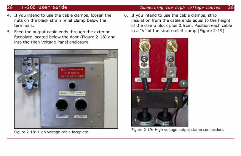
4. If you intend to use the cable clamps, loosen the nuts on the black strain relief clamp below the terminals.
5. Feed the output cable ends through the exterior faceplate located below the door (Figure 2-18) and into the High Voltage Panel enclosure.
Figure 2-18: High voltage cable faceplate.
6. If you intend to use the cable clamps, strip insulation from the cable ends equal to the height of the clamp block plus 0.5 cm. Position each cable in a “V” of the strain relief clamp (Figure 2-19).
Figure 2-19: High voltage output clamp connections.

29 Chapter 2 Preparing for Field Use Connecting the high voltage cables 29
7. Connect the cables securely to the output terminals, using either the clamps (Figure 2-19) or the threaded posts (Figure 2-20).
8. Attach the free ends of the cables to suitable high voltage electrodes.
Figure 2-20: High voltage output posts and ring type connections.
Tip Do not close the doors until you have verified the output voltage range. See “Selecting the high voltage range” on page 34.

30 T-200 User Guide Connecting the high voltage cables 30

31 Chapter 3 31
Chapter
Starting the T-200
Now that you have prepared the engine and transmitter for use and connected the cables, you are ready to start the transmitter operating system and the engine.
This chapter tells you how to:• use the T-200 safely.• start the Transmitter Controller.• start the Engine and clear Engine faults.

32 T-200 User Guide Using the T-200 Safely 32
Using the T-200 Safely
Warning! Ensure that all personnel working with or near the T-200 understand the safety information on page 4.
Before operating the T-200, verify the following:• Ground cables of the correct gauge have been
connected (see “Grounding the chassis and high-voltage leak detector” on page 25).
• Two high voltage output cables of the correct gauge have been connected from the electrodes to the high voltage output terminals using ring type connectors, with no wire strands left loose.
• Any oil or fuel spills have been cleaned up.• All tools and debris have been removed from the
interior.• There are no leaks, missing components, unfilled
reservoirs, unfastened caps or corrosion.• All Access Panels and Doors, except Door 1, are
closed and secured.• The engine exhaust pipe is unobstructed and the
protective cap moves freely.
• No flammable materials are near the engine exhaust pipe or near the radiator exhaust (Access Panel 3).
• The air intakes and exhausts (Access Panels 1 to 6) are unobstructed.
• All personnel are aware of the location and operation of the Emergency Stop buttons on the controllers.
Activating emergency stop
Pressing the transmitter EMERG. STOP button (Figure 3-1) will immediately stop electrical power output, without affecting the engine. Pressing the engine EMERGENCY STOP button on the MICROPROCESSOR ENGINE CONTROLLER (Figure 3-2) will stop the engine, but electrical output may continue for a fraction of a second.
Press these buttons if there seems to be any immediate risk to personnel or to the T-200.
!

33 Chapter 3 Starting the T-200 Using the T-200 Safely 33
To activate the transmitter emergency stop:
1. Press the red EMERG. STOP button (Figure 3-1).
Figure 3-1: Transmitter EMERG. STOP button.
2. To reset the button, turn it clockwise and release.
To activate the engine emergency stop:
1. Press the red EMERGENCY STOP button on the MICROPROCESSOR ENGINE CONTROLLER (Figure 3-2).
Figure 3-2: Engine EMERG. STOP button.

34 T-200 User Guide Preparing to start the T-200 34
2. To reset the engine emergency stop, press the OFF button, then press the two RESET buttons simulta-neously (Figure 3-3).
Figure 3-3: Engine controller OFF button and RESET buttons.
Preparing to start the T-200
Selecting the high voltage range
The T-200 AC Generator generates voltage in two ranges:
• 800VAC (maximum transmitter output 1000V and 160A).
• 1400VAC (maximum transmitter output 1600V and 100A).
Before starting the system, select the range to be used.
Danger! Do not attempt to change the voltage range while the T-200 is powered!
To select the voltage range:
1. Open Door 3 on the left side of the housing. See “Location of Controls and Major Components” on page 89.

35 Chapter 3 Starting the T-200 Preparing to start the T-200 35
2. Release the two latches and open the High Voltage Panel door.
Figure 3-4: High voltage switch set for 1400VAC.
3. Set the triple-pole, double-throw switch to the desired voltage range: upward for 1400VAC, downward for 800VAC (Figure 3-4). Ensure that the blades are fully seated.
4. Close the Panel door and secure the latches.
5. Close Door 3 and secure the latch.
Working in cold temperatures
Note Preparations must be made to allow the engine to be started in extremely cold conditions.
• Ensure that a glycol-based antifreeze solution has been installed in the engine cooling system (see “Adding coolant to the engine cooling system” on page 20).
• Use a winter grade fuel to reduce the risk of wax deposits in the fuel injection system. Refer to the ENERFLEX PowerSystems Maintenance and Instruction Manual, section 4.20 page 33.
• Use a synthetic rather than mineral-based engine oil suitable for the prevailing temperature. Refer to

36 T-200 User Guide Preparing to start the T-200 36
the ENERFLEX PowerSystems Maintenance and Instruction Manual, section 4.20, page 25.
Preheating the engine coolant
The engine coolant should be preheated for several hours before starting the engine in cold weather.
To preheat the engine coolant:
1. Open Access Panel 5 and find the engine and alternator Heater Switches. (Figure 3-5).
2. Connect a 10A, 220V AC power source to the switch box.
3. Turn the ENGINE HEATER switch ON. (The ALTERNATOR heater is used only to dry the windings of the AC Generator when it has been exposed to dampness. Do not use it now.)
4. After the preheating period and before starting the engine, turn the switch OFF, remove the AC power source, and close Access Panel 5. Figure 3-5: Engine and alternator Heater Switches.

37 Chapter 3 Starting the T-200 Starting the transmitter controller 37
Starting the transmitter controller
Finding the controls
The T-200 is operated from two Controllers behind Door 1: the CURRENT SOURCE controller and the MICROPROCESSOR ENGINE CONTROLLER. See “Location of Controls and Major Components” on page 89. The T-200 can also be operated from a remote controller connected to the CURRENT SOURCE controller.
To access the Controllers, open Door 1.
Connecting the remote controller
The remote controller makes it convenient to operate the T-200 at a distance of up to 30m from the transmitter. Although the controller can be connected at any time, it is good practice to set it up before starting the transmitter.
To connect the remote controller:
1. Remove the protective caps from the REMOTE CONTROL connectors on the main and remote controllers by pushing them in and turning them counterclockwise.
2. Remove the protective cap from each end of the remote control cable by grasping the cap and turning the locking ring counterclockwise.
3. Fit the cable ends to the controller connectors and turn the locking rings clockwise until they lock.
4. Ensure that both the main and remote HV switches are in the HV OFF position.
Starting the transmitter controller
To start the transmitter controller:
1. Ensure that the high voltage switch is set for the required voltage range (see “Selecting the high voltage range” on page 34) and that the high voltage panel door and Door 3 are both closed and latched. (The T-200 will not transmit otherwise.)

38 T-200 User Guide Starting the transmitter controller 38
2. To power the system, insert the key into the POWER key slot and turn it counterclockwise one-quarter turn. Wait approximately 30s for the controller displays to light. (Figure 3-6):• In the STATUS rectangle, the SYSTEM READY lamp
lights and the UTC:MIN:SEC digits begin accumulating time; the colons start flashing. (The Global Positioning System (GPS) receiver will not synchronize with the satellite signal until the engine has been turned on.)
• In the OUTPUT rectangle, the DRIVE lamps and the two SET lamps light, the VOLTAGE display shows the selected voltage range (either 1OOO or 16OO (V), and the CURRENT digits display the default 2O.O (A).
• In the SETUP rectangle, the MODE and SEC lamps light, the MODE characters display FD, and the PERIOD/FREQUENCY digits display 256 (seconds).
Figure 3-6: Controller at power up.

39 Chapter 3 Starting the T-200 Starting the transmitter controller 39
• For safety, the engine controller enters emergency stop mode. On the MICROPROCESSOR ENGINE CONTROLLER, the OFF lamp and EMERGENCY STOP lamp light.
3. Reset the MICROPROCESSOR ENGINE CONTROLLER by pressing the two reset buttons simultaneously (see Figure 3-3 on page 34).
Note If the engine temperature is less than 25ºC, a LowEngineTemperature alarm will be triggered on the MICROPROCESSOR ENGINE CONTROLLER. Silence the alarm by pressing the two SILENCE buttons simultaneously (Figure 3-7). You will reset this alarm in the next procedure.
4. If you have connected the remote controller, insert its key into the POWER key slot and turn it counter-clockwise one-quarter turn.
After about 30s, the remote controller displays will light with the same indications as the main controller.
Figure 3-7: Alarm SILENCE buttons.
Note The speed of serial communication between the main and remote controllers limits the refresh rate of the remote controller display. At transmission frequencies higher than 0.1Hz, the remote controller DRIVE and HIGH VOLTAGE lamps will light steadily, rather than flashing at the frequency displayed.
40 T-200 User Guide Starting the engine 40
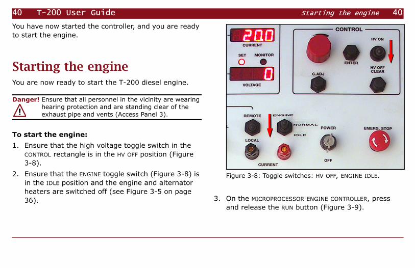
You have now started the controller, and you are ready to start the engine.
Starting the engineYou are now ready to start the T-200 diesel engine.
Danger! Ensure that all personnel in the vicinity are wearing hearing protection and are standing clear of the exhaust pipe and vents (Access Panel 3).
To start the engine:
1. Ensure that the high voltage toggle switch in the CONTROL rectangle is in the HV OFF position (Figure 3-8).
2. Ensure that the ENGINE toggle switch (Figure 3-8) is in the IDLE position and the engine and alternator heaters are switched off (see Figure 3-5 on page 36).
Figure 3-8: Toggle switches: HV OFF, ENGINE IDLE.
3. On the MICROPROCESSOR ENGINE CONTROLLER, press and release the RUN button (Figure 3-9).
!

41 Chapter 3 Starting the T-200 Starting the engine 41
Figure 3-9: MICROPROCESSOR ENGINE CONTROLLER, RUN button.
• After a brief delay, the diesel engine starts and runs at idle speed of 1036 rpm.
• After a variable delay, the GPS lamp lights, indicating satellite synchronization.
4. Ensure that the PRESSURE gauge registers an engine oil pressure of at least 280kPa.
5. In warm weather, move the ENGINE toggle switch to the NORMAL position. In cold weather, allow the engine to idle for several minutes, then move the ENGINE toggle switch to the NORMAL position. Allow the engine to warm up under no load until the temperature gauge registers at least 60ºC.
If you prefer a digital readout of the temperature, press and release the NEXT button on the MICROPROCESSOR ENGINE CONTROLLER repeatedly until the display shows the engine temperature.
6. If the LowEngineTemperature alarm was triggered in the previous procedure, reset the alarm by simulta-neously pressing the two RESET buttons on the MICROPROCESSOR ENGINE CONTROLLER. (The T-200 will not transmit if there are any active alarms.)
7. If you started the engine with the ENGINE toggle switch in the IDLE position, move it to the NORMAL position.
The engine speed increases to 1846 rpm.

42 T-200 User Guide Starting the engine 42
Note Note: Check the engine oil pressure and temperature periodically during operation. Normal oil pressure is 300–500 kPa; normal temperature is 70–95ºC. The first time the engine is used, check the oil level after one hour (see “Adding engine oil” on page 11).
With the engine running at operating temperature and normal speed, you are ready to begin transmitting. See the next chapter for instructions.

43 Chapter 4 43
Chapter
Transmission Modes andFrequency Stepping
This chapter explains the transmission modes and frequencies available. It also tells you how to use the TblEdit program on a PC to create startup files and to control automatic frequency stepping.
Use of the frequency-stepping tables is explained in Chapter 5.

44 T-200 User Guide Understanding the transmission modes 44
Understanding the transmission modesThe T-200 Current Source output is adjustable for both frequency domain (FD) and time domain (TD) methods. In time domain, output can be bipolar or unipolar.
The T-200 has a built-in table of frequencies that can be selected manually using the controller, as explained in Chapter 5. However, Phoenix current source controllers and System 2000.net receivers are also capable of automatically transmitting and receiving specific signal frequencies according to a GPS-synchronized schedule. (The built-in frequency table contains only a small subset of the frequencies that are possible using a schedule.)
Frequency stepping schedules
Schedule files can be created on a PC and the files transferred to the instruments, or a schedule can be created by the instruments in real time, calculated
from a small set of parameters. Schedule files created for the T-200 specify a waveform, a series of frequencies, a duration for each frequency, and the requested current for each frequency. Schedule files are binary files (not text files) and have the extension .tfs.
Schedules created by the T-200 in real time are determined by a few parameters saved in a file. These schedules specify a waveform, a series of frequencies, a minimum duration for each frequency, a minimum number of cycles for low frequencies, and the requested current. Optionally, an automatic current roll-off can be specified to prevent inductive loads from triggering a fault at higher frequencies.
Phase
For synchronization with other Phoenix GPS-equipped instruments, the phase is such that if the waveform were extended backward in time, the centre of the positive on time (or the negative on time in unipolar negative) would align with 2000/01/01 00:00:00 UTC.

45 Chapter 4 Frequency Stepping Understanding the transmission modes 45
Note Leap seconds may occur at the beginning of January or July every few years, as determined by the International Earth Rotation and Reference Systems Service (IERS). If a leap second happens to occur while the transmitter is generating a waveform, there may be a discrepancy of 1s in its phase. To prevent problems, consult the IERS Web site (www.iers.org) for notifications, and avoid transmitting during the occurrence of a leap second.
Frequency
The T-200 derives frequencies from a 921.6kHz base frequency, and therefore may not be able to produce exactly the requested frequency. Use at least 6 (preferably 8) significant digits when specifying a frequency. The T-200 will calculate the closest approximation possible.
The highest frequencies available are 256Hz for frequency domain modes; 4Hz for time domain modes; and 4Hz for the special FD9 mode .
For best results, select frequencies from the tables in Appendix C, page 101.)
Automatic modes
The T-200 can be programmed to follow an automatic frequency-stepping schedule, and can also be programmed to start up in a pre-determined configuration. Two different automatic frequency-stepping modes are available: the file-based mode and the parameter-based mode.
The files controlling automatic operation must be present on the CompactFlash (CF) card, which must be installed before powering on the T-200. The startup configuration and parameter-based frequency stepping configuration (explained next) are stored in a file with the extension .tbl. Frequency-stepping schedules are stored in files named with a number from 2 to 9 and the extension .tfs.
When these binary .tbl and .tfs files are saved on an instrument’s CF card, you can choose which schedule to activate by selecting an Auto mode on the T-200
f 9f+( )

46 T-200 User Guide Understanding the transmission modes 46
controller. You can also specify when creating the startup configuration (.tbl) file which schedule to activate when the instrument is powered on.
In order to synchronize the transmitter and receivers, identical schedules must be activated on all instruments used in a survey.
When a System 2000.net transmitter or receiver is powered on, it searches the CF card for a file named Startup.tbl. If it finds such a file, it uses the parameters contained in that file. If a Startup.tbl file is not found, the instrument starts up in its default configuration.
Parameter-based frequency stepping. In the parameter-based mode (Auto-1 in the T-200 display), the instrument builds a frequency-stepping table that can contain up to 100 entries, including up to 20 that you specify. This mode includes an automatic current roll-off feature that helps to avoid problems with inductive loads. The TblEdit program allows you to specify and save the parameters in a file with the extension .tbl. The file name must be the reserved name, Startup.tbl.
The advantage of the parameter-based mode is that you can set only a few parameters and have the instrument calculate all the table entries automatically following the pattern you establish. (If you want to specify more unique entries, it is better to use the file-based mode.)
File-based frequency stepping. In the file-based mode (Auto-2 to Auto-9 in the T-200 display), the instrument reads a schedule of frequencies (with associated durations and current levels) from a schedule file stored on the CF card. The TblEdit program allows you to create, modify, and save schedule files. Each file can contain up to 100 entries specifying the waveform, the frequency, the current, and the duration. Schedule files have the extension .tfs.
Note A schedule (.tfs) file contains only frequency-stepping parameters. A table (.tbl) file contains more than just frequency-stepping parameters. A table file may also specify that a particular schedule file is to be loaded at startup.
Schedule alignment to UTC. The system calculates each schedule in the automatic modes to begin at 00:00:00

47 Chapter 4 Frequency Stepping Understanding the transmission modes 47
UTC each day and repeat continuously. For this reason, it is best to plan your schedules so that an integral number of repetitions can occur in a 24-hour period. If the total duration of your schedule does not divide evenly into 24h and you happen to be working at 00:00:00 UTC, you will experience an abrupt return to the first frequency in the schedule.
Waveforms. Table 4-1 on page 48 illustrates the waveform that will be generated for each time domain and frequency domain code setting in the schedule files.
Controller Display. During operation, the MODE display in the SETUP rectangle shows an abbreviation denoting the waveform. The first two characters denote the domain—either TD (time domain) or FD (frequency domain). If these two characters are followed by a number, that number represents the percentage duty cycle or the special compound waveform, FD9. Finally, if the output is not bipolar, the last character is either P for unipolar positive or N for unipolar negative.

48 T-200 User Guide Understanding the transmission modes 48
Table 4-1: Transmission Modes and Resulting Waveforms
ControllerDisplay
Domain RatioON:OFF
Duty Cycle Waveform
TD5O Time 1:1 50%bipolar
TD33 Time 1:2 33.33%bipolar
TD25 Time 1:3 25%bipolar
= Aligned with 2000/01/01 00:00:00 UTC.
1 : 1 : 1 : 1
1 : 2 :1 : 2
1 : 3 : 1 : 3

49 Chapter 4 Frequency Stepping Understanding the transmission modes 49
TD5OP Time 1:1 50%unipolar positive
TD33P Time 1:2 33.33%unipolar positive
TD25P Time 1:3 25%unipolar positive
TD5ON Time 1:1 50%unipolar negative
TD33N Time 1:2 33.33%unipolar negative
Table 4-1: Transmission Modes and Resulting Waveforms (continued)
ControllerDisplay
DomainRatio
ON:OFFDuty Cycle Waveform
= Aligned with 2000/01/01 00:00:00 UTC.
1 : 1 : 1 : 1
1 : 2 :1 : 2
1 : 3 : 1 : 3
1 : 1 : 1 : 1
1 : 2 :1 : 2

50 T-200 User Guide Using CompactFlash cards 50
Using CompactFlash cards The T-200 can be operated using its built-in default parameters. However, in most cases it is preferable to
TD25N Time 1:3 25%unipolar negative
FD Frequency — 100%bipolar
FD9 Frequency 10:8 55.55% bipolar
Table 4-1: Transmission Modes and Resulting Waveforms (continued)
ControllerDisplay
DomainRatio
ON:OFFDuty Cycle Waveform
= Aligned with 2000/01/01 00:00:00 UTC.
1 : 3 : 1 : 3
1 : 1
f 9f+( )
:1 1
1:1

51 Chapter 4 Frequency Stepping Using CompactFlash cards 51
use pre-programmed parameters and frequency-stepping tables saved on a CompactFlash (CF) card. This section explains what kind of card to use and how to handle, store, and format CF cards.
The CF card fits into a slot in the front of the T-200, protected by a small watertight cover.
Protect CF cards from damage by storing them in plastic or fabric cases when they are not in use.
Types and quality of CF cards
CF cards from different manufacturers may not be compatible with Phoenix instruments. Not all CF cards are of high enough quality to assure reliable storage and transfer of data. The type of card sold for use in digital cameras and other consumer electronics is not suitable for geophysical use. Phoenix supplies CF cards that are rated for industrial use over a wide temperature range and are 100% factory tested.
Use only CF cards supplied by Phoenix
The external CF card and the internal CF card containing the T-200 operating system must be the same type from the same manufacturer. Mixing card types may destroy the internal or external CF card or otherwise damage the T-200. Use only the cards supplied by Phoenix.
Warning Never insert or remove a CompactFlash card when the T-200 is powered.
Do not mix different brands of CF cards. Use only the cards supplied by Phoenix. Serious damage to the unit may result if either of these warnings is ignored.
To access the CompactFlash card slot :
1. Locate the card slot on the front of the control panel behind Door 1.
2. Unlock the card slot cover by lifting the ring on the handle and turning it 90° counterclockwise.
!

52 T-200 User Guide Using CompactFlash cards 52
3. Lift the slot cover away from the instrument.
To insert the CompactFlash card :
1. Ensure that the T-200 is powered off.
2. Hold the CompactFlash card by the bottom corners, with the front of the card facing the hole for the slot cover lock.
3. Slide the card gently into the slot and press it into place.
To remove the CompactFlash card :
1. Ensure that the T-200 is powered off.
2. Eject the card partially by pressing the small square button beside it.
3. Hold the card by the two corners and withdraw it from the slot.
To replace the card slot cover :
1. Align the ring of the slot cover at right angles to the length of the cover.
2. Place the bevelled edge of the cover against the card slot opening and push on the cover handle until the cover is flat against the panel.
3. Turn the cover handle one-quarter turn clockwise to lock.
Formatting a CF card
CompactFlash cards must be correctly formatted before use.
The formatting utilities provided by CF card manufacturers are not compatible with Phoenix instruments. CompactFlash cards must use the FAT or FAT16 file system applied by the Windows formatting utility. Do not format as FAT32 or NTFS.
Tip If you experience PC system crashes when inserting a CompactFlash card into the reader, the problem may be caused by static electricity. Touch a grounded object such as an unpainted area of the computer case before inserting the card.

53 Chapter 4 Frequency Stepping Preparing files using TblEdit 53
To format a CompactFlash card :
1. Insert the card into a card reader connected to the PC.
2. Double click My Computer.
3. Right-click the CompactFlash card drive letter and click Format…
4. If your operating system is Windows XP, be sure that the File system is set to FAT. (In earlier Windows versions, the file system is always FAT.)
5. If desired, type a volume label (a name for the card).
6. If Quick Format is selected, clear the checkbox.
7. Click Start.
When formatting is complete (it takes only a few seconds), click Close. The card is ready for use in Phoenix instruments.
Preparing files using TblEditTblEdit (“Table Editor”) is a program that runs on a Windows PC, providing a graphical interface that allows you to create startup table files (.tbl) and schedule files (.tfs) easily.
Note that in normal practice, you will create at the same time startup and/or schedule files for all the instruments used in the survey. Therefore, you will need to know the serial numbers of all the instruments and sensors and other factors such as expected contact resistance, power-line frequency, and planned site spacing before you begin working with TblEdit.
This section describes how to use TblEdit to set up only the T-200. For complete information on the TblEdit program and instructions for setting up other instruments in the System 2000.net family, refer to the System 2000.net User Guide.

54 T-200 User Guide Preparing files using TblEdit 54
Overview
The general sequence of steps when using TblEdit is:
1. Set up the acquisition parameters (the geophysical method to be used, gains, filters, sensor serial numbers, etc).
2. Set up the site parameters (receiver serial numbers, channel assignments, array layout, survey project information, etc.)
3. Set up automatic frequency stepping (file-based, parameter-based, or both), or if manual control will be used, set up the starting frequency.
4. Optionally, set up radio communication parameters.
5. Save startup files for all the instruments.
6. Copy the startup and schedule files to the CF card(s) to be used in the instruments.
Starting the program
Start TblEdit as you would any other Windows program: either double click a desktop shortcut, or select the program from the Start menu.
Setting up the acquisition parameters
The geophysical method chosen determines the parameters available in the rest of the program’s windows. Therefore the method and its associated gains, filters, and so on must be selected first.
To set up the acquisition parameters:
1. From the Edit menu, select Acquisition Parameters…
The Acquisition Parameters dialog box appears. (See Fig. 4-1.)

55 Chapter 4 Frequency Stepping Preparing files using TblEdit 55
Fig. 4-1: The Acquisition Parameters dialog box.
2. In the Function area, select the method. (See Fig. 4-2.)
Fig. 4-2: The Function area of the Acquisition Parameters dialog box.
3. Set the remaining parameters according to your survey conditions. Refer to the System 2000.net User Guide for instructions.
Setting up the site parameters
The site parameters include the serial numbers of the receivers, channel assignments, array layout, and project information. Refer to the System 2000.net User Guide for instructions on setting up site parameters for the method you are using.
To set up site parameters:
1. In the Acquisition Parameters dialog box, click the Site Setup button. (See Fig. 4-3.)

56 T-200 User Guide Preparing files using TblEdit 56
Fig. 4-3: The Site Setup button.
The Input V8 and TMR Serial Number dialog box appears.
Fig. 4-4: The Input V8 and TMR Serial Number dialog box.
2. Type the 4-digit serial numbers of the V8 and/or RXU-TMR and click OK.
The Site Setup dialog box for the selected method appears. (See Fig. 4-5.)
Fig. 4-5: The Site Setup dialog box (IP method shown).
3. Enter the information required for the method you are using, according to the System 2000.net User Guide.

57 Chapter 4 Frequency Stepping Preparing files using TblEdit 57
4. For SIP, TDIP, or TDEM, enter the information required in the Array Layout area for the T-200 dipole or loop length and location co-ordinates.
5. Click OK to close the Site Setup dialog box, and again to close the Acquisition Parameters dialog box.
Note When you use an RXU-TM for current monitoring, the RXU-TM is referred to as the “Transmitter” when assigning channel numbers in TblEdit.
Setting a default frequency (non-Auto modes)
If you don’t plan to use automatic frequency stepping, you may still find it convenient to program the T-200 to start up ready to transmit at a particular, default frequency.
To set a default frequency:
1. From the Edit menu, select Frequency Stepping Parameters…
The Frequency Stepping Parameters dialog box for the selected method appears. (See Fig. 4-6.)
Fig. 4-6: The Frequency Stepping Parameters dialog box (SIP method shown).
2. From the Freq. stepping control list, choose No Step.
The Requested frequency of 0 becomes highlighted in red.
58 T-200 User Guide Preparing files using TblEdit 58
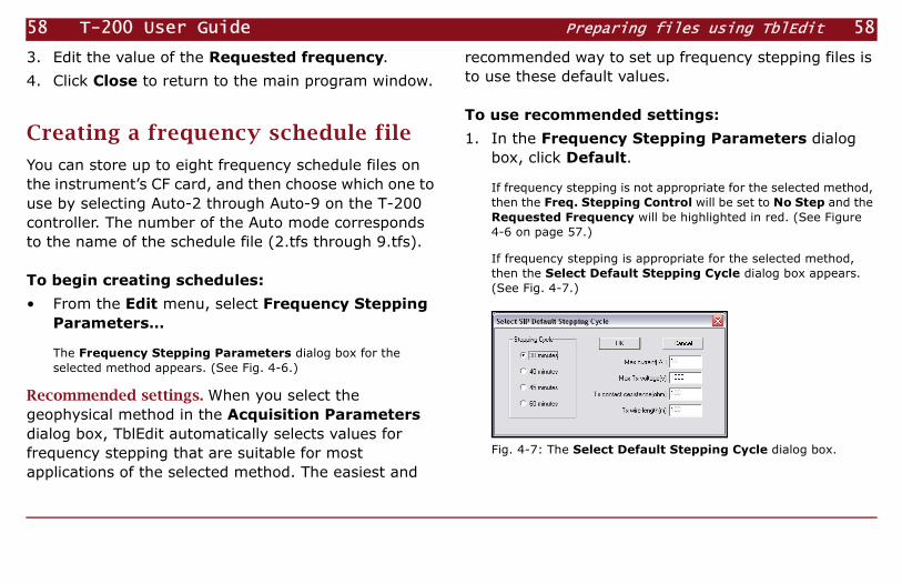
3. Edit the value of the Requested frequency.
4. Click Close to return to the main program window.
Creating a frequency schedule file
You can store up to eight frequency schedule files on the instrument’s CF card, and then choose which one to use by selecting Auto-2 through Auto-9 on the T-200 controller. The number of the Auto mode corresponds to the name of the schedule file (2.tfs through 9.tfs).
To begin creating schedules:
• From the Edit menu, select Frequency Stepping Parameters…
The Frequency Stepping Parameters dialog box for the selected method appears. (See Fig. 4-6.)
Recommended settings. When you select the geophysical method in the Acquisition Parameters dialog box, TblEdit automatically selects values for frequency stepping that are suitable for most applications of the selected method. The easiest and
recommended way to set up frequency stepping files is to use these default values.
To use recommended settings:
1. In the Frequency Stepping Parameters dialog box, click Default.
If frequency stepping is not appropriate for the selected method, then the Freq. Stepping Control will be set to No Step and the Requested Frequency will be highlighted in red. (See Figure 4-6 on page 57.)
If frequency stepping is appropriate for the selected method, then the Select Default Stepping Cycle dialog box appears. (See Fig. 4-7.)
Fig. 4-7: The Select Default Stepping Cycle dialog box.
59 Chapter 4 Frequency Stepping Preparing files using TblEdit 59
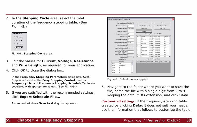
2. In the Stepping Cycle area, select the total duration of the frequency stepping table. (See Fig. 4-8.)
Fig. 4-8: Stepping Cycle area.
3. Edit the values for Current, Voltage, Resistance, and Wire Length, as required for your application.
4. Click OK to close the dialog box.
In the Frequency Stepping Parameters dialog box, Auto Step is selected as the Freq. Stepping Control, and the Frequency List and Frequency Stepping Schedule Table are populated with appropriate values. (See Fig. 4-9.)
5. If you are satisfied with the recommended settings, click Export Schedule File…
A standard Windows Save As dialog box appears.
Fig. 4-9: Default values applied.
6. Navigate to the folder where you want to save the file, name the file with a single digit from 2 to 9 keeping the default .tfs extension, and click Save.
Customized settings. If the frequency-stepping table created by clicking Default does not suit your needs, use the information that follows to customize the table.

60 T-200 User Guide Preparing files using TblEdit 60
You can edit the parameters that were used to create the Frequency Stepping Schedule Table. (See “Setting up an Auto Stepping frequency table” on page 61.) You can also edit the table directly.
Note If any of the frequencies in the Frequency Stepping Schedule Table are invalid (they cannot be generated accurately from the base clock frequency of 921.6kHz), they will be highlighted in red. You should correct these values using the tables in Appendix C, page 101, before continuing.
To customize the Frequency Stepping Schedule Table:
1. If you want TblEdit to recreate the Table starting from different parameters, read the next section and change the parameters accordingly.
If you want to edit the table directly, do any of the following:
• Click any cell of the table and type a new value.
• Click any cell of the table, then click and drag to select individual characters or groups of characters. Type new values.
• Click Insert Row to insert a new blank row above the selected cell. Click in the new cells and type new values.
• Click Delete Row to delete the entire row containing the selected cell.
2. When you have finished editing the table, click Export Schedule File…
A standard Windows Save As dialog box appears.
3. Navigate to the folder where you want to save the file, name the file with a single digit from 2 to 9 keeping the default .tfs extension, and click Save.
4. If you want to create additional schedule files, repeat this procedure, saving each file with a different name.

61 Chapter 4 Frequency Stepping Preparing files using TblEdit 61
Tip You can save schedule files using names that are more meaningful than the digits from 2 to 9. However, because of the correspondence between the file name and the Auto mode number, only files named with the digits 2 to 9 can be used by the T-200. Therefore, when copying files to the CF card, make sure that you rename the schedule files you want to use.
Setting up an Auto Stepping frequency table
In the Auto Stepping mode (Auto-1 in the T-200 display), the instrument builds a frequency-stepping schedule in real time in a pattern determined by parameters that you specify. The parameters are saved in a table file, and no external schedule of frequencies needs to be loaded. The schedule created from the parameters can contain up to 100 entries, including up to 20 non-pattern frequencies that you specify. The advantage of the Auto Stepping mode is that you can set only a few parameters and have the instrument calculate all the table entries automatically. (If you
want to specify more non-pattern entries, it is better to use the file-based mode.)
Recommended settings. The advice given under “Creating a frequency schedule file” on page 58 to use the Default button is also applicable to Auto Stepping. Customization of the Auto Stepping parameters is more complex than for schedule files.
Customized settings. If the frequency-stepping schedule created by clicking Default does not suit your application, use the information that follows to customize the schedule.
The instrument creates the frequency stepping schedule using three types of parameters:
• FREQn, specified values for the first frequencies in the schedule (1≤n≤20).
• Lowest frequency, an approximate value for the last frequency in the schedule.
• Frequencies per octave, an integer that determines the number of frequencies per octave to complete the schedule automatically. (An octave is

62 T-200 User Guide Preparing files using TblEdit 62
the span between two frequencies, one of which is twice the other.)
Although you can specify all 20 values for the FREQn parameter, you will typically specify only a few of them, establishing a starting frequency and/or a pattern of frequency stepping, and allowing the Lowest frequency and Frequencies per octave to determine the remaining schedule entries based on that starting frequency or pattern.
Note When specifying the first frequencies in the schedule, always start with FREQ1 and work consecutively. Unused parameters should be set to a value of 0.
Specifying non-pattern and pattern frequencies. You can specify one or more frequencies at the beginning of the schedule—for example, a 1Hz test signal—that will not affect the automatic calculation of the remaining frequencies. As explained below, the automatic calculation is based on the frequencies in the last octave that you specify.
To specify frequencies:
1. In the Frequency Stepping Parameters window of TblEdit, edit the FREQ1 Frequency cell, assigning it a value less than or equal to the highest frequency suitable for the method you’re using (256Hz for frequency domain, 4Hz for time domain, or 4Hz for the special FD9 mode).
2. Edit one or more cells from FREQ2–FREQ20, assigning them the desired frequencies. End with the sequence of frequencies that you want to use as the frequency-stepping pattern.
3. Leave all remaining FREQn cells set to a value of 0.
Selecting a frequency-stepping pattern. There are two patterns that can complete the frequency schedule:
• Equally spaced divisions of descending octaves, starting with the last non-zero value of the specified frequencies.
• A sequence of frequencies (equally or unequally spaced) per descending octave, based on the last sequence of specified frequencies that are in descending order and span less than an octave.

63 Chapter 4 Frequency Stepping Preparing files using TblEdit 63
Tip To gain a better understanding of how Auto-stepping works and to see typical parameter values for the geophysical method you’re using, click Default in the Frequency Stepping Parameters window.
To select equally spaced divisions of the octave:
1. In the Frequency Stepping Parameters window, choose Auto Step as the Freq. stepping control.
2. Edit the Lowest frequency parameter, assigning it the approximate value of the lowest frequency you want. (As explained under “Frequency” on page 45, not all frequencies can be generated by the T-200.)
3. Edit the Frequencies per octave parameter, assigning it the number of frequencies per octave you want.
4. Click Calculate Step(Wnd) Table to update the Frequency Stepping Schedule Table.
When TblEdit completes the schedule, it will start with the last non-zero value of FREQn and repeatedly multiply by
until the schedule is full or the Lowest frequency has been reached.
To select a repeating sequence of frequencies per octave:
1. In the Frequency Stepping Parameters window, choose Auto Step as the Freq. stepping control.
2. Start with the lowest-numbered unassigned parameter among FREQ1–FREQ20. Edit that parameter, assigning it the highest frequency of the pattern.
3. Edit the next parameters in sequence, assigning them consecutively lower frequencies in the pattern. The difference between the first and last frequencies of the sequence must be less than an octave. Ensure the remaining FREQn parameters are set to a value of 0.
4. Click Calculate Step(Wnd) Table to update the Frequency Stepping Schedule Table.
When TblEdit completes the schedule, it will repeatedly divide each frequency in the sequence by 2 until the schedule is full or the Lowest frequency has been reached.
Setting up the timing. Three parameters control the timing:
2 1 Frequencies per octave( )⁄–

64 T-200 User Guide Preparing files using TblEdit 64
• Cycles per frequency, the minimum number of cycles generated for each frequency. (The Time per frequency parameter may cause a longer duration for a given frequency.) Use Cycles per frequency to ensure that enough cycles of very low frequencies are transmitted.
• TPFR, Time per frequency, the duration in seconds for which each frequency is generated, unless the Cycles per frequency parameter causes a longer duration for a given frequency. Use Time per frequency to set the duration for the relatively high frequencies.
• TTOT, Total time, controls the duration in seconds of the entire table. If Total time = 0, then the length of the schedule is controlled by Time per frequency and Cycles per frequency. If Total time is not 0, then the schedule is truncated or the duration of the last frequency is extended accordingly. It is best to use Total time to ensure that your schedule can be repeated an integral number of times in 24h. (See “Schedule alignment to UTC” on page 46.)
To set up the schedule:
1. Edit the Time per frequency, Cycles per frequency, and Total time parameters, assigning them the appropriate values for your application.
2. Click Calculate Step(Wnd) Table to update the Frequency Stepping Schedule Table.
Setting up automatic current reduction (roll-off). If the transmitter load is inductive, then the achievable current will drop as frequency increases. If the output current falls too far below the requested current, a fault will be triggered. To avoid this condition, set up a roll-off frequency in Auto Stepping to reduce the requested current as frequency increases. The effect of automatic current reduction is shown in Fig. 4-10.
Two parameters control the automatic reduction of requested current:
• Transmitted LF current (Transmitted Low Frequency current), in amperes.
• Rolloff corner frequency, the frequency at which the requested output current will be reduced to about 70% of Transmitted LF current.

65 Chapter 4 Frequency Stepping Preparing files using TblEdit 65
The transmitted current for each frequency f in the table is equal to:
To set up automatic current reduction:
1. Edit the Transmitted LF current and Rolloff corner frequency parameters, assigning them the appropriate values for your application.
2. Click Calculate Step(Wnd) Table to update the Frequency Stepping Schedule Table.
Completing the Auto Stepping setup. Click Close to return to the TblEdit main window, and turn to “Saving the startup files” on page 66 to complete the file preparation.
Fig. 4-10: Automatic current reduction.
Setting up radio communication
If you plan to use radio networking among the other System 2000.net instruments (V8, RXU-TMR, RXU) used in the survey, you should set up the communication parameters at this time. All instruments used in a survey must have compatible
LF transmitted current
1 f( ) Rolloff corner frequency( )⁄( )2+( )-------------------------------------------------------------------------------------------------------------------
LF current
Rol
loff
Increasing frequency
Req
uest
ed c
urre
nt
corn
er

66 T-200 User Guide Preparing files using TblEdit 66
settings. Refer to the System 2000.net User Guide for instructions.
Note The T-200 does not support radio communication directly from the transmitter. Use an RXU-TMR to acquire transmitter data and communicate with other instruments on a radio network.
Specifying the frequency-stepping default
After you create one or more schedule files or set up Auto-stepping in a table file, you can specify which condition should apply when the T-200 starts up. If you specify that a schedule file should be used, it must be present on the instrument’s CF card.
To specify the frequency-stepping default:
• From the Freq. stepping control list, select No Step, Auto Step, or the name of the file you want to be loaded when the T-200 starts up. (See Fig. 4-11.)
Fig. 4-11: Selecting a default schedule (.tfs) file.
Saving the startup files
After you have set up the survey parameters and/or Auto-stepping parameters, you should save startup table files to a folder on your PC.
Saving the T-200 startup table file. With current T-200 software, the file name must be Startup.tbl. Follow these instructions to save the T-200 startup table file. (You can also use this procedure to save the receiver startup table files; they should be named with their respective serial numbers.)
To save a single startup file:
1. From the File menu, select Save As.
A standard Windows Save As dialog box appears.

67 Chapter 4 Frequency Stepping Preparing files using TblEdit 67
2. Navigate to the folder where you want to save the file.
3. Name the file with either the receiver’s serial number or, for the T-200, the reserved name Startup, keeping the default .tbl extension, and click Save.
Saving multiple receiver startup table files. You can name and save a series of files manually as just described, but TblEdit makes it easy to save files for all the survey receivers at once.
To save files for all receivers:
1. From the File menu, select Save *.TBL Files for All Boxes
The Save RXUTMR Startup File dialog box appears. (See Fig. 4-12.)
2. If required, edit any of the RXU parameters displayed in the dialog box.
3. In the File Name area, select SerialNumber.tbl.
Fig. 4-12: The Save RXUTMR Startup File dialog box, with the mouse pointer on the Location ellipsis button.
4. Click the Location ellipsis button (see Fig. 4-12) and navigate to the folder where you want to save the files.

68 T-200 User Guide Preparing files using TblEdit 68
5. Click OK to select the folder and click OK to save the RXU startup table file.
The Save V8 Startup File dialog box appears. (See Fig. 4-13.)
6. If required, edit any of the V8 parameters displayed in the dialog box.
7. In the File Name area, select SerialNumber.tbl.
8. Click OK to save the V8 startup table file in the same folder as the other startup files.
Fig. 4-13: The Save V8 Startup File dialog box.

69 Chapter 4 Frequency Stepping Preparing files using TblEdit 69
Copying the files to CF cards
When a System 2000.net receiver is powered on, it searches the CF card for a startup table (.tbl) file named with its own serial number. If such a file is found, the parameters in it determine the instrument’s configuration. The only other similar file that an instrument will use is one with the reserved name, Startup.tbl.
This design means that you can copy all of the table files that you saved in the previous step to all the CF cards used in the survey: the instruments will simply ignore table files named with serial numbers other than their own. The advantage is that any CF card prepared in this way can be installed in any instrument. There is therefore no risk that the wrong table file will be used or that the correct table file will be missing.
If you choose to use the file name Startup.tbl for each instrument, you will have to manage the copying of files and installation of cards individually and much more carefully.
To copy the files to the CF cards:
• Put each CF card in your card reader in turn and use the Windows commands (drag and drop or copy and paste) to copy all the receivers’ serial-numbered table files and the T-200’s Startup.tbl file to every card.
Editing saved schedule files
Schedule files are binary files that cannot be edited in a text editor. However, you can easily open them in TblEdit, either to examine their content or to make changes.
To edit a saved schedule file:
1. From the Edit menu, choose Frequency Stepping Parameters…
The Frequency Stepping Parameters dialog box appears.

70 T-200 User Guide Preparing files using TblEdit 70
Fig. 4-14: The Frequency Stepping Parameters dialog box with Open Schedule File button disabled.
2. If the Open Schedule File button is disabled, then from the Freq. stepping control list, choose any numbered .tfs file name. (The choice you make has no effect on which file is actually opened.)
The Open Schedule File button is enabled.
3. Click Open Schedule File.
A standard Windows Open dialog box appears.
4. Navigate to the folder containing the file you want to edit, and click Open.
5. Examine and/or edit the Frequency Stepping Schedule Table as explained earlier in this chapter.
6. To save the schedule file with the same or a different name, click Export Schedule File, or to discard the changes, click Close.

71 Chapter 5 71
Chapter
Transmitting with the T-200
The T-200 Current Source output is adjustable for both Frequency domain (FD) and Time domain (TD) techniques. In Time domain, output can be bipolar or unipolar.
This chapter explains how to operate the T-200 in manual and automatic modes.
This chapter also explains how to start and stop transmission, and how to make and monitor adjustments during operation.

72 T-200 User Guide Setting the parameters in manual modes 72
Setting the parameters in manual modesTo set the parameters, you will press the SELECT button (Figure 5-1) to move from one parameter to the next, and turn the adjustment knob in the CONTROL rectangle to change each parameter value (Figure 5-2).
Figure 5-1: The SELECT button.
Figure 5-2: Adjustment knob, ENTER button, and high voltage toggle switch.
Note To set most parameters, the high voltage toggle switch must be in the HV OFF position (Figure 5-2).

73 Chapter 5 Transmitting Setting the parameters in manual modes 73
Selecting the main or remote controller
The T-200 can be operated from either the main or remote controllers. (See “Connecting the remote controller” on page 37.) When one controller is active, the other is in monitoring mode and its controls are inoperative. (Exception: EMERGENCY STOP can always be activated from the main controller.)
To select the main or remote controller:
1. Ensure that the high voltage toggle switch on both controllers is in the HV OFF position.
2. Toggle the REMOTE CONTROL switch to the REMOTE position or the LOCAL position as desired (Figure 5-3).
The two controllers may take one or two seconds to synchronize displays.
Figure 5-3: REMOTE/LOCAL toggle switch.
Setting the transmission mode
To set the transmission mode:
1. Press and release the SELECT button (Figure 5-1).
In the SET UP rectangle, the MODE lamp lights and the MODE display starts flashing.
2. Turn the adjustment knob in the CONTROL rectangle (Figure 5-2) either way until the desired trans-mission mode is displayed. Refer to Table 4-1 on page 48 for the meaning of the MODE displays.

74 T-200 User Guide Setting the parameters in manual modes 74
Tip Use a quick, short motion of the adjustment knob to change the display by one mode at a time. Use a quick, full turning motion to move rapidly through several modes.
Setting the period or frequency
To set the period or frequency:
1. Press and release the SELECT button (Figure 5-1).
In the SET UP rectangle, the MODE display stops flashing and
the PERIOD/FREQUENCY display starts flashing.
2. Turn the adjustment knob in the CONTROL rectangle (Figure 5-2) either way until the desired period or frequency is displayed.
Consult “T-200 Frequency Tables” on page 101 for the range of values available in time and frequency domains in manual modes.
Tip The digits displayed may represent either period or frequency. Ensure that the SEC or HZ lamp indicates your intention.
Pre-setting the current
To set the current before transmitting:
1. Press and release the SELECT button (Figure 5-1).
The PERIOD/FREQUENCY display stops flashing. In the OUTPUT
rectangle, the SET lamps light and the CURRENT display starts flashing (Figure 5-4).
2. Turn the adjustment knob in the CONTROL rectangle (Figure 5-2) either way until the desired current in amperes is displayed.
3. Press the ENTER button in the CONTROL rectangle (or the SELECT button again) to finish setting the param-eters (Figure 5-2).
The current display stops flashing and the DRIVE “+” and “–”
lamps in the output rectangle light. The main controller DRIVE
lamps will flash if the frequency is ≤0.5Hz; the remote controller
DRIVE lamps will flash if the frequency is ≤0.1Hz.

75 Chapter 5 Transmitting Transmitting in manual modes 75
Figure 5-4: SET lamp and CURRENT display.
Tip Transmit initially at 20A in order to calculate the load resistance and maximum current for the voltage range selected. Setting the current too high will trigger a fault.
Transmitting in manual modesWith the parameters correctly set, you are ready to transmit, monitor voltage and current levels, and adjust the parameters if required (Figure 5-5).
For instructions on transmitting in non-manual modes, see “Transmitting using an external clock” on page 79, “Automatic frequency stepping using parameters (Auto-1 mode)” on page 80, and “Transmitting using schedule files (Auto-2 to Auto-9)” on page 82.

76 T-200 User Guide Transmitting in manual modes 76
Figure 5-5: Ready to transmit.

77 Chapter 5 Transmitting Transmitting in manual modes 77
Starting transmission
To start transmitting:
• Move the high voltage toggle switch up to the HV ON position.
In the OUTPUT rectangle:
• The CURRENT and VOLTAGE displays will change as the AC Generator produces the output current.
• The DRIVE “+” and “–” lamps continue to flash alternately at the rate set in the PERIOD/FREQUENCY display (low frequencies only).
• At the start of the next positive pulse in the waveform, the HIGH VOLTAGE “+” and “–” lamps will light in unison with the DRIVE lamps. (At very low frequencies, there may be a noticeable delay until the positive pulse begins and the HIGH VOLTAGE and DRIVE lamps synchronize.)
The T-200 is now transmitting (Figure 5-6).
Figure 5-6: Transmission in progress. The HIGH VOLTAGE and DRIVE lamps light in unison, CURRENT and VOLTAGE displays show the output levels, and the two MONITOR lamps are lit.

78 T-200 User Guide Transmitting in manual modes 78
Adjusting the current while transmitting
The current can be changed while the high voltage toggle switch is in the HV ON position.
To adjust the current:
1. In the CONTROL rectangle, press and hold the C.ADJ button (Figure 5-2).
2. Watch the CURRENT display and turn the adjustment knob until the desired current is displayed. Use caution when approaching the calculated maximum.
3. Release the C.ADJ button.
Adjusting the frequency while transmitting
The frequency can be changed while the high voltage toggle switch is in the HV ON position.
To adjust the frequency:
1. Press and hold the SELECT button.
2. Watch the FREQUENCY display and turn the adjustment knob in the CONTROL rectangle until the desired frequency is displayed.
3. Release the SELECT button.
The display returns momentarily to the previous frequency, then displays the new frequency.
Changing the mode
Transmission must be interrupted to change the mode. (The period/frequency and the the current can also be changed at this time.)
To re-adjust the mode and other parameters:
1. Move the high voltage toggle switch down to the HV OFF position to interrupt transmission.
2. Press and release the SELECT button once to change mode, twice to change period/frequency, or three times to change current.

79 Chapter 5 Transmitting Transmitting using an external clock 79
The affected parameter display starts flashing.
3. Turn the adjustment knob in the CONTROL rectangle to change the value.
4. Press the SELECT button to go to the next parameter, or press the ENTER button to end the adjustments.
5. To resume transmission, move the high voltage toggle switch up to the HV ON position.
Transmitting using an external clockIn applications where phase measurements are critical, it can be desirable to have the transmitter timing controlled by an external device. For example, a Phoenix RXU-TM connected to the T-200 can control the transmitted frequency and waveform while simultaneously acquiring data.
Newer Phoenix clocks operate from a programmable frequency table that is synchronized to UTC by GPS signals. Once the clock achieves satellite lock, it
determines how much of the active table has elapsed and loads the appropriate frequency. However, the transmitter does not begin transmission in the middle of a pulse, so there may be a delay before output begins.
Note If you turn on the clock or change the active table just after the UTC-synchronized start-time of a low frequency, there will be a noticeable delay before the next start-time, when transmission will begin. At very low frequencies, this delay could be 20 min or more.
Connecting an external clock
The external clock controller can be any of several Phoenix devices, but is usually an RXU-TM. Use the same procedure to connect any of the controllers.
To connect an external clock:
1. Remove the protective caps on the clock output connector and on the T-200 EXT DRIVE connector by pushing in and turning counterclockwise.

80 T-200 User Guide Automatic frequency stepping using parameters (Auto-1 mode) 80
2. If the cable you are using has protective caps, remove them by holding the cap and turning the locking ring counterclockwise.
3. Fit the cable to the transmitter and clock connectors and turn the locking rings clockwise until they lock.
4. If the cable has protective caps, keep them clean by joining them to the transmitter and clock caps.
Transmitting under clock control
Under external clock control, only the current can be adjusted on the T-200 controllers.
To transmit under external clock control:
1. Ensure that the T-200 high voltage toggle switch is in the HV OFF position.
2. Turn on the external clock.
3. On the T-200 controller, press and release the SELECT button.
4. In the set up rectangle, the MODE display starts flashing.
5. Turn the adjustment knob in the control rectangle in either direction until EXTCLK appears in the display.
6. In the CONTROL rectangle, press ENTER.
7. Move the high voltage toggle switch up to the HV ON position.
Transmission is now under the control of the external clock. As explained in the note above, with GPS-synchronized clocks, there may be a significant delay before the first output.
8. If necessary, adjust the current (see “Adjusting the current while transmitting” on page 78).
Automatic frequency stepping using parameters (Auto-1 mode)The Auto-1 mode of the T-200 creates and follows a frequency-stepping table and a current roll-off curve according to parameters that you saved using the TblEdit program. See Chapter 4 for instructions.

81 Chapter 5 TransmittingAutomatic frequency stepping using parameters (Auto-1 mode) 81
Verifying the Auto-1 table
The frequency-stepping table of Auto-1 mode is stored within the T-200, not the PC you use to create it. However, you can view the contents of the table on the T-200 controllers.
To verify the Auto-1 mode table:
1. On the T-200 controller, press and release the SELECT button.
In the SET UP rectangle, the MODE lamp lights and the MODE display starts flashing.
2. Turn the adjustment knob in the CONTROL rectangle either way until AUTO-1 is displayed.
3. Press and release the SELECT button again.
In the SET UP rectangle, the MODE display stops flashing and
the PERIOD/FREQUENCY display starts flashing.
4. Turn the adjustment knob either way and watch the PERIOD/FREQUENCY display and the CURRENT display to see the frequency and current values in the frequency-stepping table.
5. When you are satisfied, press ENTER.
Transmitting under Auto-1 control
To begin transmitting on the Auto-1 schedule:
1. Ensure that the GPS lamp in the STATUS rectangle is lit. (If not, wait for GPS synchronization to be achieved and the lamp to light.)
2. Select AUTO-1 mode.
Note If the mode display reads –––––– when you expect to see the name of an Auto mode, then that mode has not been properly set up. Review the preceding instructions.
3. Move the high voltage switch up to the HV ON position.
The T-200 synchronizes the table and phase to GPS and loads the presently scheduled frequency. There may be a slight delay before output begins, since transmission will not begin in the middle of a pulse.

82 T-200 User Guide Transmitting using schedule files (Auto-2 to Auto-9) 82
Transmitting using schedule files (Auto-2 to Auto-9)Auto modes 2–9 are similar to Auto-1 mode in that they allow transmission based on a stored frequency-stepping table. However, in these modes, you create the tables in the TblEdit program and save them on a CF card along with the T-200’s Startup.tbl file. The files are named with the digits 2 to 9 and the extension .tfs. The correspondingly numbered Auto modes are then available for use in transmission. See Chapter 4 for instructions.
Verifying uploaded schedules
The frequency-stepping tables of modes Auto-2 to Auto-9 are stored within the T-200, and you can view the contents of the tables on the T-200 controllers.
To verify the Auto mode tables:
1. On the T-200 controller, press and release the SELECT button.
In the SET UP rectangle, the MODE lamp lights and the MODE display starts flashing.
2. Turn the adjustment knob in the CONTROL rectangle either way until AUTO- is displayed with the number of the schedule file you want to verify.
3. Press and release the SELECT button again.
In the SET UP rectangle, the MODE display stops flashing and
the PERIOD/FREQUENCY display starts flashing.
4. Turn the adjustment knob either way and watch the PERIOD/FREQUENCY display and the CURRENT display to see the frequency and current values in the frequency-stepping table.
5. When you are satisfied, press ENTER.

83 Chapter 5 Transmitting Responding to faults and alarms 83
Transmitting under Auto-2 to Auto-9 control
To begin transmitting on an Auto-2 to Auto-9 schedule:
1. Ensure that the GPS lamp in the STATUS rectangle is lit. (If not, wait for GPS synchronization to be achieved and the lamp to light.)
2. Select the Auto mode you want to use.
Note If the mode display reads –––––– when you expect to see the name of an Auto mode, then that mode has not been properly set up. Review the preceding instructions.
3. Move the high voltage switch up to the HV ON position.
The T-200 synchronizes the table and phase to GPS and loads the presently scheduled frequency. There may be a slight delay before output begins, since transmission will not begin in the middle of a pulse.
Responding to faults and alarmsThe transmitter controller constantly monitors the state of the T-200 and will shut off high voltage transmission and trigger an alarm if any fault conditions arise.
If a fault condition occurs, fault lamps will light in the FAULTS rectangle on the controller (Figure 5-7).
Figure 5-7: Fault lamps.

84 T-200 User Guide Responding to faults and alarms 84
Clearing fault conditions
To respond to a transmission fault:
1. Move the high voltage toggle switch down to the HV OFF position.
2. Consult the table below and “Understanding and Clearing Faults” on page 93 for the meaning of the fault lamps and the means of resolving fault condi-tions.
3. When the condition is corrected, press the CLEAR button in the CONTROL rectangle (Figure 5-8) to turn off the fault lamps.
Figure 5-8: Fault CLEAR button.
4. Change the transmission parameters if necessary (some fault conditions will reset the transmitter to the default parameters) and resume transmitting.

85 Chapter 5 Transmitting Stopping transmission and shutting down the T-200 85
Stopping transmission and shutting down the T-200At the end of a transmission session, you will need to stop transmitting, allow the engine temperature to stabilize, and either turn the engine off or allow it to idle until the next session.
Stopping transmission
To stop transmission:
• Move the high voltage toggle switch down to the HV OFF position.
In the OUTPUT rectangle:
• The HIGH VOLTAGE lamps stop flashing.
• The MONITOR lamps go out and the SET lamps light.
• The VOLTAGE display shows the selected voltage range (either 1OOOV or 16OOV).
Table 5-1: Fault Lamp Key
Lamp Meaning
CH Current High.
CL Current Low.
VH Voltage High.
VL Voltage Low.
RST Reset required.
TEMP Temperature out of range.
EF Engine Fault.
DL Door Lock.
WS Warning—Software.
HVL High Voltage Leak.

86 T-200 User Guide Stopping transmission and shutting down the T-200 86
Idling the engine
To idle the engine in between transmission sessions:
• Move the Engine toggle switch down to the IDLE position.
Warning! Do not idle the engine for long periods. Idling or running at low load for long periods causes soot to build up on critical engine parts.
Stabilizing the engine temperature
When the T-200 operates under load for a period of time, the engine stores a great deal of heat. If you turn the engine off before this heat has dissipated, the coolant may boil and the engine may be damaged. Although you can stabilize the engine temperature by running the engine at normal speed with no load for 5 minutes before turning it off, we recommend that you use the AUTO shutdown feature. This feature
automatically turns the engine off after a cool-down period.
Turning the engine off automatically
To turn the engine off automatically:
• Press the AUTO button on the MICROPROCESSOR ENGINE CONTROLLER.
The engine runs for approximately 5 minutes and then stops.
Turning the engine off manually
To turn the engine off manually:
• Press the OFF button on the MICROPROCESSOR ENGINE CONTROLLER.
The engine takes several seconds to stop completely.
!

87 Chapter 5 Transmitting Stopping transmission and shutting down the T-200 87
Shutting down the transmitter controller
To shut down the T-200 transmitter controller completely:
1. Ensure that the engine has come to a complete stop.
2. Turn the POWER key clockwise one-quarter turn.
The controller lamps and displays all go out.

88 T-200 User Guide Stopping transmission and shutting down the T-200 88

89 89
Appendix
Location of Controls and MajorComponents
This appendix provides a top view of the T-200 with call-outs to help locate controls and components.
Refer to the ENERFLEX PowerSystems Maintenance and Instruction Manual, section 3.20, page 9 for additional diagrams of the engine.

90 T-200 User Guide 90
+
– +
–
FRO
NT
REARAC Generator
1 2 3 4 5 76 8 9 10 11 12
13
14
15
1617181920212223242526272829303132
33
34

91 Appendix A Location of Components 91
1 Chassis Ground
2 Controllers
3 Door 1
4 Controller Ground
5 Door 2
6 Batteries
7 Access Panel 1
8 Air Filter Indicator
9 Engine Oil Filler
10 Access Panel 2
11 Rear Roof Hatch
12 Radiator Cap
13 Access Panel 3
14 Dummy Load
15 Engine Coolant Level Indicator
16 Fuel Filters
17 Engine Coolant Drain Valve
18 Fuel Supply Valve
19 Fuel Return Valve
20 Engine Oil Drain Valve
21 Access panel 4, Fuel Connection Box below
22 Manual Fuel Pump
23 Engine Oil Sight Glass
24 Access Panel 5
25 Fuel Injectors
26 Heater Switches
27 Door 3
28 High Voltage Panel
29 Door 4
30 Front Roof Hatch
31 Transmitter Coolant Reservoir
32 Chassis Ground
33 Access Panel 6
34 Transmitter Coolant Drain Valve

92 T-200 User Guide 92

93 93
Appendix
Understanding and Clearing Faults

94 T-200 User Guide 94
Table B-1: Fault indications and resolutions
DisplayAssociated FAULTS
LED*Meaning Resolution†
ERR-01 DL Power unit enclosure is open. Open Door 4, close power unit enclosure and secure latches.
ERR-02 DL High Voltage Panel enclosure is open.
Open Door 3, close High Voltage Panel enclosure and secure latches.
ERR-03 DL Controller enclosure is open. Close Controller enclosure and secure latches.
ERR-04 TEMP Electrical power unit overheated.
Check transmitter coolant system for fluid level and proper operation. Check thermal switch for proper operation. If no fault found, contact Phoenix.
ERR-05 EF Engine in idle mode, or engine fault.
Move the ENGINE toggle switch to the NORMAL position before transmitting. (The fault will clear automatically; there is no need to press the CLEAR button.)Refer to the ENERFLEX PowerSystems Maintenance and Instruction Manual, section 4.50, page 16 for descriptions and resolutions of engine faults.
ERR-06 WS EMERG. STOP button pressed. Turn EMERG.STOP button clockwise to reset.

95 Appendix B Faults 95
ERR-07 WS POWER key turned off before engine shut off.
Turn POWER key counterclockwise one-quarter turn. Follow the instructions for “Stopping transmission and shutting down the T-200” on page 85.
ERR-08 HVL High voltage leak, ground. Contact Phoenix.
ERR-09 HVL High voltage leak, hot. Contact Phoenix.
ERR-10 WS High voltage switch not closed. Ensure that the high voltage switch blades are fully seated. See “Selecting the high voltage range” on page 34..
ERR-11 WS Engine not running Follow the instructions for “Starting the engine” on page 40.
ERR-12 CH Dummy load IGBT over current. Contact Phoenix.
ERR-13 CH IGBT1 or IGBT3 over current. Contact Phoenix.
ERR-14 CH IGBT2 or IGBT4 over current. Contact Phoenix.
ERR-15 CH Current high (detected by software in Auto modes, otherwise detected by hardware).
If running in Auto mode, revise the current setting(s) to lower level(s). If not running in Auto mode, contact Phoenix.
Table B-1: Fault indications and resolutions
DisplayAssociated FAULTS
LED*Meaning Resolution†

96 T-200 User Guide 96
ERR-16 CL Current low (detected by software in Auto modes, otherwise detected by hardware).
If running in Auto mode, revise the current setting(s) to lower level(s). If not running in Auto mode, check for abnormally high resistance in load cables and electrodes. If no fault found, contact Phoenix.
ERR-17 VL Voltage low (hardware detected).
Check for abnormally low resistance in load cables and electrodes. If no fault found, contact Phoenix.
ERR-18 VH Voltage high (hardware detected).
Transmit at 20A, noting voltage displayed. Use Ohm’s law to calculate load resistance. Use load resistance and selected voltage range (1000V or 1600V) to calculate maximum current. Transmit at or below calculated maximum. If fault recurs, contact Phoenix.
ERR-19 WS In Auto mode, the file or parameters specify mixed or undefined waveforms or a frequency out of range.
In Auto-1 mode, correct the WFRM parameter value. In Auto-2, -3, -4 modes, ensure that only one waveform type is specified in each CSV file. Ensure that you have not requested a frequency below 1/1024Hz, or above 256Hz (Frequency Domain) or 4Hz (Time Domain).
ERR-20 Not used.
Table B-1: Fault indications and resolutions
DisplayAssociated FAULTS
LED*Meaning Resolution†

97 Appendix B Faults 97
ERR-21 WS Remote controller EMERG. STOP activated.
Reset EMERG. STOP button on remote controller.
ERR-22 WS 1) With remote controller connected, HV switch is toggled ON at inactive controller; or2) In Auto modes, HV switch is toggled ON before GPS lock is achieved.
When remote controller is connected, ensure HV switch is toggled OFF at the inactive controller. In Auto modes, wait for GPS lamp to light steadily before toggling HV switch ON.
ERR-23 WS With remote controller connected and active, communication with the T-200 has been lost.
Check remote controller cable and connections.
ERR-24 WS External clock has requested a frequency that is out of range.
Ensure that external clock does not request a frequency below 1/1024Hz, or above 256Hz (Frequency Domain) or 4Hz (Time Domain).
ERR-25 HVL High voltage leak detector test failed.
Contact Phoenix.
Table B-1: Fault indications and resolutions
DisplayAssociated FAULTS
LED*Meaning Resolution†

98 T-200 User Guide 98
ERR-26 WS AC Generator bearings or windings overheated.
Contact Phoenix.
ERR-27 WS AC Generator bearings or windings overheated.
Contact Phoenix.
ERR-28 WS AC Generator bearings or windings overheated.
Contact Phoenix.
ERR-29 WS AC Generator bearings or windings overheated.
Contact Phoenix.
ERR-30 WS Maximum power exceeded. Contact Phoenix.
ERR-31 Not used.
ERR-32 Not used.
*CH = current high; CL = current low; DL = Door Lock; EF = engine fault; HVL = high voltage leak; RST = reset required; TEMP = temperature fault; VH = voltage high; VL = voltage low; WS = warning–software
Table B-1: Fault indications and resolutions
DisplayAssociated FAULTS
LED*Meaning Resolution†

99 Appendix B Faults 99
Note †After correcting a fault, press the CLEAR button in the CONTROL rectangle to reset the system. If the remote controller was active when the fault occurred, switch to LOCAL control, clear the fault at the T-200 controller, then switch back to REMOTE.

100 T-200 User Guide 100

101 101
Appendix
T-200 Frequency Tables
This appendix provides tables of frequencies and periods for three modes:• Frequency domain• Time domain• Frequency domain FD9 mode
When specifying a frequency in a frequency table, use at least 6 (preferably 8) significant digits. The T-200 will calculate the closest approximation possible.
The T-200 controller displays frequencies and periods with a fixed decimal point and only two decimal places. However, the frequency actually transmitted will be as shown in these tables.

102 T-200 User Guide 102
Table C-1: Frequency Domain Frequencies and Periods
Hz s Hz s Hz s Hz s256 215.3271028 180.9897879 152.1796565
128 107.6132648 90.49489395 76.11496531
64 53.81920112 45.25633471 38.05748266
32 26.91195795 22.6259452 19.02874133
16 13.45087279 11.3129726 9.51437066
8 6.72548547 5.6564863 4.75718533
4 3.36274274 2.82824315 2.37859267
2 1.6813683 1.41412158 1.18929633
1 0.84068415 1.1895 0.70706079 1.4143 0.59464817 1.6817
0.5 2 0.42034208 2.3790 0.35353039 2.8286 0.29732408 3.3633
0.25 4 0.21017104 4.7580 0.1767652 5.6572 0.14866204 6.7267
0.125 8 0.10508552 9.5161 0.0883826 11.3144 0.07433102 13.4533
0.0625 16 0.05254276 19.0321 0.0441913 22.6289 0.03716551 26.9067
0.03125 32 0.02627138 38.0642 0.02209565 45.2578 0.01858276 53.8133
0.015625 64 0.01313569 76.1285 0.01104782 90.5156 0.00929138 107.6266
0.0078125 128 0.00656784 152.2571 0.00552391 181.0312 0.00464569 215.2533
0.00390625 256 0.003283904 304.5156 0.00276196 362.0617 0.00232284 430.5075
0.00195313 512 0.00164196 609.0282 0.00138098 724.1234 0.00116142 861.0150
0.00097656 1024

103 Appendix C Frequency Tables 103
Table C-2: Time Domain Frequencies and Periods
Hz s4 0.25
2.5 0.4
2 0.5
1 1
0.5 2
0.25 4
0.125 8
0.06666667 15
0.0625 16
0.03333333 30
0.03125 32
0.01666667 60
0.015625 64
0.00833333 120
0.0078125 128
0.00416667 240
0.00390625 256
0.00208333 480
0.00195313 512
0.00104167 960
0.00097656 1024

104 T-200 User Guide 104
Table C-3: FD9 Mode Frequencies and Periods
Hz s4 0.25
2.5 0.4
2 0.5
1 1
0.5 2
0.25 4
0.125 8
0.0666667 15
0.06250000 16
0.03333333 30
0.03125000 32
0.0166667 60
0.01562500 64
0.00833333 120
0.00781250 128

105 105
Appendix
Specifications
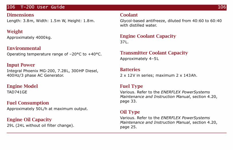
106 T-200 User Guide 106
DimensionsLength: 3.8m, Width: 1.5m W, Height: 1.8m.
WeightApproximately 4000kg.
EnvironmentalOperating temperature range of –20°C to +40°C.
Input PowerIntegral Phoenix MG-200, 7.28L, 300HP Diesel, 400Hz/3 phase AC Generator.
Engine ModelTAD741GE
Fuel ConsumptionApproximately 50L/h at maximum output.
Engine Oil Capacity29L (24L without oil filter change).
CoolantGlycol-based antifreeze, diluted from 40:60 to 60:40 with distilled water.
Engine Coolant Capacity37L.
Transmitter Coolant CapacityApproximately 4–5L
Batteries2 x 12V in series; maximum 2 x 143Ah.
Fuel TypeVarious. Refer to the ENERFLEX PowerSystems Maintenance and Instruction Manual, section 4.20, page 33.
Oil TypeVarious. Refer to the ENERFLEX PowerSystems Maintenance and Instruction Manual, section 4.20, page 25.

107 Appendix D Specifications 107
Oil Pressure300–500kPa; minimum 150kPa.
Idle Speed1036 rpm.
Normal Speed1846 rpm.
Normal Engine Temperature70–95°C.
Output CurrentMaximum 160A at 1000V.Maximum 100A at 1600V.
Output VoltageMaximum 1000V or 1600V.
Output PowerMaximum 160kW.
WaveformsFrequency Domain:Bipolar square wave selectable from:• continuous (100% duty cycle).• fundamental plus 9th harmonic (ON/OFF ratio of
10:8; 55.55% duty cycle).Frequency range: 1/1024Hz to 256Hz.Time Domain:Bipolar or unipolar square wave with duty cycles of 25%, 33%, or 50%.Frequency range: 1/512Hz to 4Hz.
Turn-off time<50µs.
ControlsMicroprocessor-based controller with GPS display; remote controller.

108 T-200 User Guide 108
IndicatorsMode, Frequency/Period, Current, Voltage, Output Polarity, GPS Time (UTC), Faults.
Integrated Safety FeaturesFault detection, voltage leak detection, open door detection, emergency stop buttons, system power key.

109 109
Appendix
Maintenance

110 T-200 User Guide Introduction 110
IntroductionThe T-200 is a complex machine that will be subject to a variety of stresses—mechanical, electrical, thermal, and environmental—depending on the conditions of transportation, use, and storage. To assure safety and a long service life and to avoid unnecessary environmental damage, it is essential that the T-200 is regularly and properly maintained.
Warning! Failure to follow the service recommendations in this document may result in damage to equipment or injury to personnel and may void any warranties, expressed or implied.
For most procedures, complete instructions, specifications, and details are provided in the ENERFLEX PowerSystems Maintenance and Instruction Manual (“ENERFLEX”). Please read and understand sections 3.20 (Volvo engine) and 3.30 (Kato AC Generator) before performing any maintenance operations. In case of discrepancy between this User Guide and the ENERFLEX Manual, follow the instructions in the ENERFLEX Manual.
Note Except where noted, never attempt to perform engine or AC Generator maintenance procedures while the T-200 is running or is still hot. Always allow the system to cool to ambient temperatures before servicing any component.
Frequent Activities
Displaying operating hours
You can use the engine controller’s automatic hourmeter to determine when to perform many of the maintenance procedures described below.
To display the total number of hours the system has operated:
1. Power the system (see page 37; the engine can be running or not).
!

111 Appendix E Maintenance Frequent Activities 111
2. On the MICROPROCESSOR ENGINE CONTROLLER, press the NEXT or PREVIOUS button repeatedly until the display shows Freq on the top line.
3. Read the total Hours of operation on the second line.
Daily—engine stopped
Before starting the engine for the first time each day, perform the following operations:
Check engine oil level. Open Access Panel 5 and examine the level of oil in the sight glass. Add engine oil if necessary. See “Adding engine oil” on page 11.
Check engine coolant level. Open Access Panel 4 and examine the Engine Coolant Level Indicator. Add engine coolant if necessary. See “Adding coolant to the engine cooling system” on page 20.
Check transmitter coolant level. Open Door 2 or the Front Roof Hatch and examine the level of transmitter coolant in the reservoir. Add transmitter coolant if
necessary. See “Adding coolant to the transmitter cooling system” on page 22.
Check radiator. Inspect the radiator and if necessary, clean it. See ENERFLEX, section 3.20, page 31, “Cooler (charge air cooler TAD). External cleaning.”
Check air filter indicator. The indicator is visible through Door 2 (see “Location of Controls and Major Components” on page 89). If the indicator remains in the red field when the engine is stopped, replace the filter. See ENERFLEX, section 3.20, page 21, “Air filter. Check/replace.”
Check for leakage. Inspect the T-200 generally for any signs of leaking fluids. Include a check for excess lubricant on the AC Generator bearings and seals.
Daily—engine operating
Once the engine has reached operating temperature, perform the following checks (See ENERFLEX, section 3.20, “Maintenance Schedule,” page 19):

112 T-200 User Guide Frequent Activities 112
• Check the engine oil pressure periodically during operation. Normal oil pressure is 300–500 kPa.
• Check the engine temperature periodically during operation. Normal temperature is 75–95ºC.
Every 8 hours of continuous use
If the T-200 is run continuously for long periods:
Check engine oil level. Open Access Panel 5 and examine the level of oil in the sight glass. Add engine oil if necessary. See “Adding engine oil” on page 11.
Every 50-600 hours
Change engine oil and filter. Depending on the grade of lubricating oil and the sulphur content of the fuel, it may be necessary to change the oil and filter as often as every 50 hours of operation. In any case, the oil and filter should be changed at least once every 12 months.
The oil and filter should always be changed at the same time, and the engine should be at operating temperature. See ENERFLEX, section 3.20, pages 25–26.

113 Appendix E Maintenance Authorized Volvo Penta service 113
Authorized Volvo Penta serviceCertain parts of the engine must be serviced by an Authorized Volvo Penta Service workshop. To locate a local workshop, contact:
AB Volvo PentaSE-405 08 GöteborgSwedenwww.penta.volvo.se
After first 150 hours. Check valve clearances and tighten fuel injector posts.
Every 1200 hours. Adjust valve clearances.
Every 2400 hours. Check fuel injectors, turbocharger, engine and equipment.
Maintenance SchedulesFor the remaining mandatory maintenance procedures and schedules, see the ENERFLEX Manual, section 3.20, p. 19–20 and section 3.30, p. 33–34, and the table that follows.

114 T-200 User Guide Maintenance Schedules 114
Table E-1: Maintenance Schedule
Repeat at this
intervalEngine Service
AC Generator Service
ENERFLEX ReferenceT-200
User Guide Reference
Comments
50 hours Check battery electrolyte levels.
Section 3.20, p. 36. Consult battery manufacturer.
Drain water from fuel prefilter.
Section 3.20, p. 33.
400 hours
Check and adjust drive belts.
Section 3.20, p. 23.
Drain fuel tank sludge collector.
Consult fuel tank manufacturer.
800 hours
Replace fuel filter and pre-filter.
Section 3.20, p. 32–33.
Check air lines. Section 3.20, p. 21.

115 Appendix E Maintenance Maintenance Schedules 115
2000 hoursor 6
months
Various tasks. Section 3.30, Maintenance Schedule, p. 33.
8000 hoursor 12
months
Various tasks. Section 3.30, “Maintenance Schedule,” p. 33.
5000 hoursor 2
years
Replace coolant. page 118.
8000 hoursor 12
months
Various tasks Section 3.30, “Maintenance Schedule,” p. 33.
Table E-1: Maintenance Schedule (continued)
Repeat at this
intervalEngine Service
AC Generator Service
ENERFLEX ReferenceT-200
User Guide Reference
Comments

116 T-200 User Guide Maintenance Schedules 116
20 000 hoursor 3
years
Various tasks Section 3.30, “Maintenance Schedule,” p. 34.
30 000 hoursor 5
years
Various tasks. Section 3.30, “Maintenance Schedule,” p. 34.
6 months
Check batteries and cables for corrosion.
Clean or replace as necessary.
Replace coolant filter.
Section 3.20, p. 31.
Various tasks. Section 3.30, “Maintenance Schedule,” p. 33.
Unnecessary if already serviced due to hours of operation.
Table E-1: Maintenance Schedule (continued)
Repeat at this
intervalEngine Service
AC Generator Service
ENERFLEX ReferenceT-200
User Guide Reference
Comments

117 Appendix E Maintenance Maintenance Schedules 117
12 months
Various tasks. Section 3.30, “Maintenance Schedule,” p. 33.
Unnecessary if already serviced due to hours of operation.
Change oil and filter.
Section 3.20, p. 24–26.
Clean charge air cooler.
Section 3.20, p. 31.
Check insulation resistances and dry windings.
Section 3.30, “Maintenance Schedule,” p. 34.
page 119.
2 years Replace coolant. page 118. Unnecessary if already serviced due to hours of operation.
3 years Various tasks. Section 3.30, “Maintenance Schedule,” p. 34.
Unnecessary if already serviced due to hours of operation.
Table E-1: Maintenance Schedule (continued)
Repeat at this
intervalEngine Service
AC Generator Service
ENERFLEX ReferenceT-200
User Guide Reference
Comments

118 T-200 User Guide Servicing the cooling systems 118
Servicing the cooling systems
Draining and flushing the engine cooling system
To drain the coolant and flush the engine cooling system:
1. Attach a drain hose to the engine coolant drain outlet at the base of the chassis and place the other end into a suitable container.
2. Follow the instructions in the ENERFLEX Manual, section 3.20, p. 30–31.
3. Follow the instructions for “Adding coolant to the engine cooling system” on page 20.
Draining and flushing the transmitter cooling system
To drain the coolant and flush the transmitter cooling system:
1. Open Access Panel 6.
5 years Various tasks. Section 3.30, “Maintenance Schedule,” p. 34.
Unnecessary if already serviced due to hours of operation.
Table E-1: Maintenance Schedule (continued)
Repeat at this
intervalEngine Service
AC Generator Service
ENERFLEX ReferenceT-200
User Guide Reference
Comments

119 Appendix E Maintenance Drying the AC Generator windings 119
2. Place the free end of the transmitter coolant drain hose into a suitable container.
3. Open the Front Roof Hatch and remove the Trans-mitter Coolant Reservoir cap.
4. Open the coolant drain valve (see Figure 2-14 on page 23).
5. Turn on the transmitter controller by turning the POWER key counterclockwise. This will start the transmitter coolant pump to ensure complete draining. (Do not start the engine.)
6. When the coolant stops draining, dispose of the used coolant according to local hazardous waste regulations.
Danger! Glycol-based antifreeze is poisonous to humans and animals.
7. Place a hose into the Transmitter coolant reservoir and flush with plain water until the draining water is clear.
8. When the water stops draining, turn off the trans-mitter by turning the POWER key clockwise.
9. Close the transmitter coolant drain valve.
10. Follow the instructions for “Adding coolant to the transmitter cooling system” on page 22.
11.Close the Front Roof Hatch and Access Panel 6.
Drying the AC Generator windingsIf the periodic maintenance inspection reveals insulation resistance below acceptable levels, or if the T-200 is subjected to dampness or condensation, it may be necessary to dry the windings of the AC Generator.
To dry the windings:
1. Refer to the ENERFLEX PowerSystems Maintenance and Instruction Manual, section 3.30, Maintenance Schedule, page 38, “Dry out procedures.”
2. Open Access Panel 5 and find the engine and alter-nator Heater Switches (see Figure 3-5 on page 36).
!

120 T-200 User Guide Drying the AC Generator windings 120
3. Connect a 10A, 220V AC power source to the switch box.
4. Turn the ALTERNATOR switch ON.
5. When the resistance returns to an acceptable level, turn the ALTERNATOR switch OFF and remove the power source.

121 121
Appendix
Time Zone Map

122
T-200 User Guide
122
11 10 9 8 7 6 5 4 3

123
Appendix F Time Zone Map
123
2 1 0 1 2 3 54

124
T-200 User Guide
124
5 6 7 8 9 10 1211

125 Index 125
Index
– – – – – – on controller display, 83
Numerics921.6 kHz base frequency, 45
AAC Generator, 34
drying windings, 119grounding, 25
acquisition parameters, setting up, 54adding
engine coolant, 22engine oil, 11transmitter coolant, 24
adjusting the current, 78air bleed valve, 18alarm, LowEngineTemperature, 39, 40alarms, 83alignment to UTC, schedule, 46
alternator, see AC Generatorantifreeze
changing, 118engine, 22transmitter, 24
applications, geophysical, 2audience, 2Auto mode number and file names, 61auto shutdown, 86auto stepping frequency table, setting
up, 61auto stepping setup, completing the, 65Auto-1 mode, 80
transmitting, 81verifying table, 81
Auto-2,3,4 modes, 82transmitting, 83
automatic current reduction (roll-off), setting up, 64
automatic frequency stepping using parameters, 80
automatic modes, 45
Bbatteries, 14, 106bipolar output, 44
CC. ADJ. button, 78cable
ground, 25output, 27
calculating load resistance, 75, 96centre of gravity, 10CF card
copying the files to, 69changing
coolant, 118engine oil, 112
chassis ground, 25checklist, safety, 32CLEAR button, 83clearing faults, 83, 93

126 Index 126
cold temperature operationadding engine coolant, 22adding transmitter coolant, 24starting the engine, 40summary, 35
CompactFlash cardinstalling and removing, 50
completing the auto stepping setup, 65Complex Resistivity, 2concerns, safety, 5connection
battery, 14external clock, 79fuel lines, 16ground, 25high voltage cables, 27remote controller, 37
contact informationPhoenix, 4Volvo Penta, 113
Controlled Source Audio Magnetotellurics, 2
controller displays – – – – – –, 83controller, remote see remote controllercontrols, location, 89coolant
capacities, 106changing, 118engine, 22transmitter, 24
copying the files to the CF card(s), 69CR (complex resistivity, 2creating a frequency schedule file, 58CSAMT, 2current
reduction (roll-off), setting up automatic, 64
setting, 78setting in manual modes, 72
customized settingsauto mode, 61frequency-stepping files, 59
Cycles per frequency parameter, 64
Ddefault frequency (non-auto modes),
setting, 57default, specifying the frequency-
stepping, 66delay before transmission, 83Delete Row button, 60diesel oil, see fueldiluting antifreeze, 22, 24dimensions, 106drain valve
engine coolant, 22engine oil, 11transmitter coolant, 24
drying AC Generator windings, 119dummy load, 5Duty Cycle, 48
Eediting saved schedule files, 69electrode
ground, 25high voltage, 27lightning protection, 27
e-mail, Phoenix, 4emergency stop, 32engine
coolantadding, 22changing, 118drain valve, 22
heater, servicing, 118oil
adding, 11capacity, 106changing, 112
preheating, 35starting, 40temperature
normal, 107temperature, stabilizing, 86
engine model, 3

127 Index 127
error messages, table of, 93exporting (saving) schedule files, 60external clock
connecting, 79transmitting, 79, 80
Ffaults
responding to, 83table of, 93
FDEM, 2features, safety, 4file extensions
TBL, 45TFS, 45
file names for auto modes, 61file-based frequency stepping, 46files
copying to the cf card(s), 69creating frequency schedule, 58editing saved schedule, 69preparing using tbleditor, 53saving startup, 66
flatbed truck, 10
flushing, cooling system, 118format
CompactFlash card, 52formatting a CF card, 52FREQn parameter, 61frequencies
specifying non-pattern and pattern, 62Frequencies per octave parameter, 61frequency
(non-auto modes), setting a default, 57
about, 45adjusting while transmitting, 78limits, 45schedule file, creating, 58setting in manual modes, 72tables, manual modes, 101
Frequency Domain Electromagnetics, 2frequency stepping
file-based, 46parameter-based, 46transmission modes and, 43
frequency tablesetting up an auto stepping, 61
frequency-steppingdefault, specifying, 66pattern, selecting, 62
fuelconsumption, 17, 106injectors, 18lines, connecting, 16pump, manual, 18safety, 16specifications, 17supply, 17system, priming, 17, 18
Ggauge, ground cable, 25geophysical applications, 2glycol, see antifreezeGPS, 2, 37, 41ground
AC generator, 25cable gauge, 25chassis, 25electrodes, 25high voltage panel, 27impedance, 25

128 Index 128
Hhearing protection, 6heater
AC Generator, 36, 119engine, 35, 118
high voltageconnections, 27range, 34
highlighted values, frequency table, 60hoses, fuel, see fuel lines
IIERS, 45impedance, ground, 25inductance problems, 27injectors, fuel, 18input power, 106Insert Row button, 60inspection, safety, 32installing
batteries, 14International Earth Rotation and
Reference Systems Service (IERS), 45
invalid frequencies, 60
Lleap seconds, 45lifting the T-200, 6lightning protection, 27load resistance, calculating, 75, 96location of controls, 89Long Period Transient
Electromagnetics, 2LoTEM, 2LowEngineTemperature alarm, 39, 40Lowest frequency parameter, 61lubrication, engine, 11, 112
Mmain controller, selecting, 73maintenance, 109
schedule (table), 114map, time zone, 121mode display, abbreviations, 47model, engine, 3
modesautomatic, 45changing while transmitting, 78manual, 72manual, frequency tables, 101non-auto, setting a default
frequency, 57
Nnoise level, 6
Ooctave, 61oil
adding, 11capacity, 106changing, 112diesel, see fueldrain valve, 11pressure, 42, 107, 112sight glass, 11synthetic, 35
operating temperature, 106

129 Index 129
outputbipolar, 44cables, 27unipolar, 44voltage range, 34
output, specifications, 107overview
preparing files, 54
Pparameter-based frequency stepping, 46parameters
setting in manual modes, 72, 78setting, manual modes, 78
pattern, selecting a frequency-stepping, 62
period, setting, 78period, setting in manual modes, 72period/frequency table, 101phase, about, 44positioning the T-200 on a vehicle, 10power, input, 106precautions, safety, 4, 32preheating the engine, 35preparing
files, using TblEditor, 53pre-setting parameters in manual
modes, 72
pressureoil, 107
pressure, oil, 42, 112priming the fuel system, 18protection
hearing, 6lightning, 27
Rradiator, 22radio communication, setting up, 65range, voltage, 34recommended settings
auto mode, 61frequency schedule file, 58
red highlight, frequency table, 60remote controller
connecting, 37powering, 39selecting, 73
reset, emergency stop, 32resetting after faults, 83, 93responding to faults and alarms, 83rolloff corner frequency parameter, 64roll-off, setting up automatic current
reduction, 64
Ssafety
features, 4information, 4inspection, 32
satellite time, see GPSSave *.TBL Files for All Boxes
command, 67saved schedule files, editing, 69saving (exporting) schedule files, 60saving the startup files, 66schedule alignment to UTC, 46schedule file
creating, 58editing saved, 69
schedule filestransmitting with, 82verifying, 82
selecting a frequency-stepping pattern, 62
selecting main or remote controller, 73SerialNumber.TBL, file name, 68setting
default frequency (non-auto modes), 57
setting parameters, 78manual modes, 72

130 Index 130
setting upacquisition parameters, 54auto stepping frequency table, 61automatic current reduction (roll-
off), 64radio communication, 65site parameters, 55timing, 63
settings, customizedauto mode, 61frequency-stepping files, 59
settings, recommendedauto mode, 61frequency schedule file, 58
shipping the T-200, 6shutdown, engine, 86sight glass, oil level, 11significant digits when specifying a
frequency, 45, 101SIP, 2site parameters, setting up, 55sound pressure level, 6specifications, T-200, 105specifying
frequency-stepping default, 66non-pattern and pattern
frequencies, 62Spectral Induced Polarization, 2stabilizing engine temperature, 86
starter batteries, 14starting
engine, 40TblEditor, 54transmitter, 37
startup files, saving, 66Startup.TBL, reserved name, 46static electricity and CF cards, 52stop, emergency, 32stopping transmission, 85support, 4switch, high voltage, 34
TT-200 specifications, 105table of frequencies/periods, 101TAD741GE, 3TblEditor
preparing files using, 53starting, 54
TDIP, 2temperature
operating range, 106temperature, normal engine, 42, 112TFS file extension, 45Time Domain Induced Polarization, 2Time per frequency parameter, 64
time signal, see GPStime zone map, 121timing, setting up, 63Total time parameter, 64TPFR parameter, 64transmission modes
frequency stepping, 43resulting waveforms, 48understanding, 44
Transmitted LF current parameter, 64transmitter
coolant drain valve, 24coolant, adding, 24coolant, changing, 118delay before output, 83starting, 37stopping, 85
transmittingAuto-1 mode, 81Auto-2, -3, or -4 mode, 83manual modes, 75using schedule files, 82with external clock, 80
truck, flatbed, 10TTOT parameter, 64turn-off time, 107

131 Index 131
Uunderstanding
transmission modes, 44unipolar output, 44using TblEditor, preparing files, 53UTC, 37
see also GPSUTC, schedule alignment to, 46
Vvalve, air bleed, 18vehicle, positioning on, 10venting, fuel system, 18verifying
Auto-1 table, 81uploaded schedules, 82
voltage range, 34Volvo Penta, 113
Wwarm-up, engine, 40waveform
setting in manual modes, 72specifications, 107
waveforms, 47transmission modes and resulting, 48
Web site, Phoenix, 4weight, 106windings, AC Generator, 119winter operation, 35