t o be finalised - parts db
TRANSCRIPT

FI Doc No: PZQ97-89010FI - Issue: 3 - 04/12/18
HILUX
16Page 01 of
Reverse Park Assist
Fitting Instructions
Fitting Time: 60 minutes
July 2015 Production Onwards
Kit Part No: PZQ97-89010
Kit Part No: PZQ97-89020
Checkers Initials
Date Checked
DRAFT
TO B
E FIN
ALIS
ED
FI Doc No: PZQ97-89010FI - Issue: 3 - 04/12/18
HILUX
16
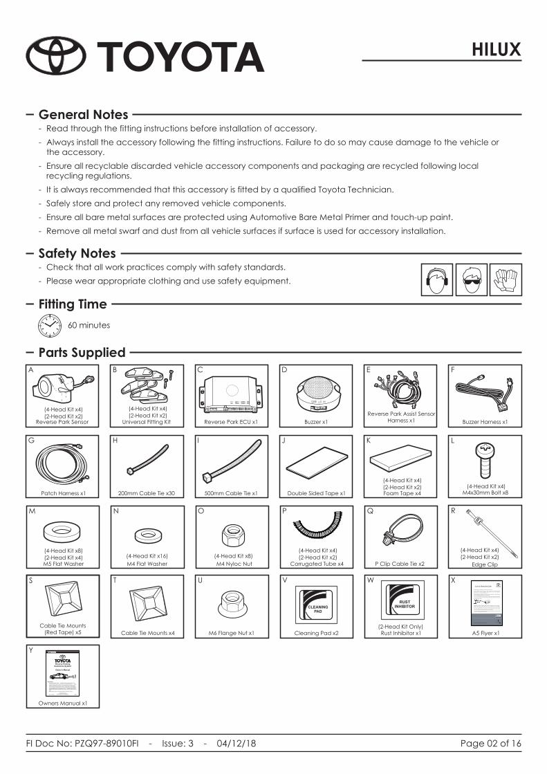
Parts Supplied
- Read through the fitting instructions before installation of accessory.
- Always install the accessory following the fitting instructions. Failure to do so may cause damage to the vehicle or the accessory.
- Ensure all recyclable discarded vehicle accessory components and packaging are recycled following local recycling regulations.
- It is always recommended that this accessory is fitted by a qualified Toyota Technician.
- Safely store and protect any removed vehicle components.
- Ensure all bare metal surfaces are protected using Automotive Bare Metal Primer and touch-up paint.
- Remove all metal swarf and dust from all vehicle surfaces if surface is used for accessory installation.
- Check that all work practices comply with safety standards.
- Please wear appropriate clothing and use safety equipment.
60 minutes
General Notes
Safety Notes
Fitting Time
Page 02 of
1
21
3
A B C D E F
G H I J K L
M N O P Q R
XT U V W
Foam Tape x4
Reverse Park Sensor Universal Fitting Kit Reverse Park ECU x1 Buzzer x1
Reverse Park Assist Sensor Harness x1 Buzzer Harness x1
Double Sided Tape x1500mm Cable Tie x1200mm Cable Tie x30 Patch Harness x1
LR
CR
CL
CL
CR
L
R
M4x30mm Bolt x8
P Clip Cable Tie x2M4 Nyloc Nut M4 Flat WasherM5 Flat Washer
Edge ClipCorrugated Tube x4
Rust Inhibitor x1Cleaning Pad x2
CLEANINGPAD
RUSTINHIBITOR
(2-Head Kit x2)
(4-Head Kit x4)
(2-Head Kit x2)
(4-Head Kit x4)(2-Head Kit x2)
(4-Head Kit x4)
(2-Head Kit x2)
(4-Head Kit x4)
(2-Head Kit x4)
(4-Head Kit x8)(4-Head Kit x16) (4-Head Kit x8)
S
Cable Tie Mounts (Red Tape) x5
Y
Owners Manual x1
COPYRIGHT Toyota 2006
Reproduction in whole or part prohibited without written approval of Toyota Australia.Pty.Ltd.RPA - TOYOTA - MT 24APR08
Reverse ParkingAssistance System
The Toyota Reverse Parking Assistance System is designed as a driver assistance device and should not be used as a substitute for safe p arking practices. Under certain circumstances the operation of this device may be impaired or possibly not work at all. The area into which the vehicle is to be reversed must be visually monitored while p arking. Ultimate responsibility to ensure that people and/or property are not harmed remains with the driver. Keep reversing speeds under five kilometres per hour . The legal responsibility for recognising and assessing objects while reversing remains with the driver at all times.
Disclaimer
Owner's Manual
Note: Exhaust vapour could trigger beeping in cold winter morning,
Cable Tie Mounts x4
(2-Head Kit x2)
(4-Head Kit x4)
(4-Head Kit x4)
M6 Flange Nut x1 A5 Flyer x12-Head Kit (2-Head Kit Only)
Live a Genuine Life
www.toyotamanuals.com.au/accessories
T2
01
5-0
00
68
9 P
SA
00
68
0
Congratulations on purchasing your Toyota Genuine Accessory.
Correct installation of your Accessory is critical to ensuring its performance and safe
operation. Before commencing installation, please consider if you have the appropriate
technical skills to successfully install this product.
Fitting instructions are available on the Toyota Service Information & Repair Manuals
website at www.toyotamanuals.com.au/accessories.
To view or download fitting instructions, enter the Accessory part number without the dash.
The part number is found on the barcode label located on the outside of the Accessory
packaging as shown below.
Please follow the fitting instructions closely using the tools specified. If cutting or drilling
templates are required, set the page scale to “none” in the print menu prior to printing.
Always confirm the template size by measuring the scale indicator before cutting or drilling.
To the extent permitted by law, Toyota Australia excludes all liability which may arise because
a user of this publication fails to follow directions in the publication.
If you have any queries regarding the installation of your Toyota Genuine Accessory, please
contact your nearest preferred Toyota Dealer.

FI Doc No: PZQ97-89010FI - Issue: 3 - 04/12/18
HILUX
16Page 03 of
Tools and Materials Required
Phillips Head Screw Driver Trim Removal Tools Phillips Head Drill BitFlat Blade Screw Driver Cutters 3mm & 5mm Drill Bit
Drill RatchetAdhesive tape ScissorsSocket - 7mm, 8mm,
10mm, 12mm

FI Doc No: PZQ97-89010FI - Issue: 3 - 04/12/18
HILUX
16Page 04 of
Step 1
1
1 1
1 1
1 1
11
1 1
1 1
1 1
11
1
11
1
Step 2
Step 3
Important
Always refer to the vehicle’s Workshop Manual when removing vehicle components.
• Note down all clock and radio settings.
• In the engine bay, disconnect the negative battery terminal (1).
Always refer to the workshop manual for assistance with parts removal.
• In the LHS front cabin, remove the LHS front scuff plate (1).
• Remove the plastic nut (2) securing the driver’s kick panel (3) and remove the kick panel (3).
3
1
• Unclip the glove box dampener (1).
Remove LH retaining clip (2) by rotating anti-clockwise.
Remove the glove Box (3).
•
•
• Remove the driver's lower dash garnish (4).
1
1
3
4
2
2
FI Doc No: PZQ97-89010FI - Issue: 3 - 04/12/18
HILUX
16Page 05 of
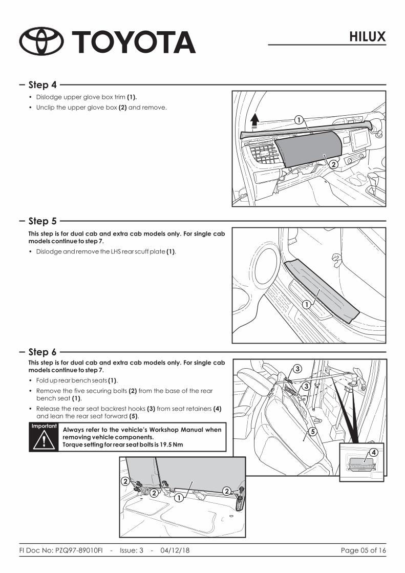
Step 4
1
1 1
1 1
11
1 1
1 11 1
11
Step 5
Step 6This step is for dual cab and extra cab models only. For single cab models continue to step 7.
• Remove the five securing bolts (2) from the base of the rear bench seat (1).
•
• Fold up rear bench seats (1).
Release the rear seat backrest hooks (3) from seat retainers (4) and lean the rear seat forward (5).
• Dislodge upper glove box trim (1).
• Unclip the upper glove box (2) and remove.
This step is for dual cab and extra cab models only. For single cab models continue to step 7.
• Dislodge and remove the LHS rear scuff plate (1).
1
1
2
3
3
4
2
1
4
3
3
5Important
Always refer to the vehicle’s Workshop Manual when removing vehicle components. Torque setting for rear seat bolts is 19.5 Nm
12 2
2
FI Doc No: PZQ97-89010FI - Issue: 3 - 04/12/18
HILUX
16
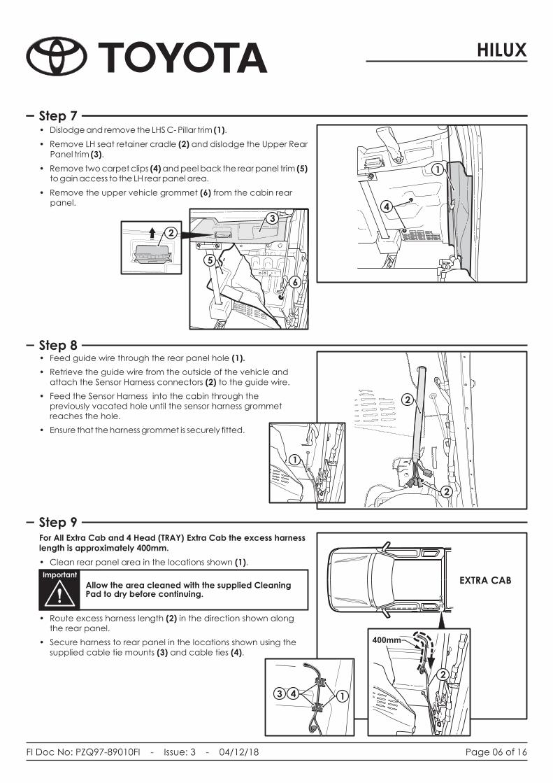
Step 7
Step 9
Page 06 of
1
2
3
3
4
1
1
1
1 1
1
1
1 1
1 11
1
11
For All Extra Cab and 4 Head (TRAY) Extra Cab the excess harness length is approximately 400mm.
Clean rear panel area in the locations shown (1).
Route excess harness length (2) in the direction shown along the rear panel.
Secure harness to rear panel in the locations shown using the supplied cable tie mounts (3) and cable ties (4).
•
•
•
TBA
EXTRA CABImportant
Allow the area cleaned with the supplied Cleaning Pad to dry before continuing.
Step 7• Dislodge and remove the LHS C- Pillar trim (1).
Remove LH seat retainer cradle (2) and dislodge the Upper Rear Panel trim (3).
• Remove two carpet clips (4) and peel back the rear panel trim (5) to gain access to the LH rear panel area.
Remove the upper vehicle grommet (6) from the cabin .
•
• rear panel
1
2
3
6
4
Step 8• Feed guide wire through the rear panel hole (1).
Retrieve the guide wire from the outside of the vehicle and attach the
Feed the Sensor Harness into the cabin through the previously vacated hole until the sensor harness grommet reaches the hole.
• Ensure that the harness grommet is securely fitted.
•Sensor Harness connectors (2) to the guide wire.
•
1
2
2
400mm
400mm
1
1
2
43
5

FI Doc No: PZQ97-89010FI - Issue: 3 - 04/12/18
HILUX
16
Step 10
Step 11
Step 12
Page 07 of
2
1
1 1
1 1
11
1 1
1 11
1
11
• Route the RPA Sensor Harness (1) along the LHS chassis towards the rear of the vehicle.
• Secure the RPA Sensor Harness (1) to the vehicle chassis and vehicle harness as shown using supplied cable ties (2) and 8mm P-Clips (3).
• Continue to route the RPA Sensor Harness (1) along the LHS chassis towards the rear of the vehicle.
• Secure the RPA Sensor Harness (1) to the vehicle chassis as shown using supplied cable ties (2).
For RPA 4 Head (TRAY) Single Cab the excess harness length is approximately 800mm.
•
•
•
under carpet edge (5)
Clean rear panel area in the locations shown (1).
Route excess harness length (2) in the direction shown along the rear panel.
Secure harness to rear panel in the locations shown using the supplied cable tie mounts (3) and cable ties (4).
Route harness (1) from rear panel towards front of vehicle
Important
Allow the area cleaned with the supplied Cleaning Pad to dry before continuing.
800mm
1
43
23
1
2 2
1
1
2
2
Important
Ensure when routing harness to avoid airbag and seat belt components. 5

FI Doc No: PZQ97-89010FI - Issue: 3 - 04/12/18
HILUX
16Page 08 of
• Continue to route the Sensor Harness (1) along the LHS chassis towards the rear of the vehicle.
• Secure Sensor Harness (1) to the vehicle on the LH & RH rear chassis flange using the two supplied Edge Clips (2).
S• ecure the remaining Sensor Harness (1) to the vehicle chassis using supplied cable ties (3).
Step 13
Step 15
Step 14For RPA 2 Head (TUB) Double Cab and 4 Head (TRAY) Extra Cab the excess harness length is approximately 400mm.
• Bundle excess harness (1) and secure to vehicle with cable ties (2) to the rear LHS chassis rail.
EXTRA CAB
DOUBLE CAB
For RPA 4 Head (TUB) Double Cab the excess harness length is approximately 800mm.
• Bundle excess harness (1) and secure to vehicle with cable ties (2) on the rear LHS chassis rail.
2 1
1 1
1 1
11
1 1
1 11
1
11
1
2
2
2
1
2
2
2
DOUBLE CAB
31
2
2
1
2
1
2
1

FI Doc No: PZQ97-89010FI - Issue: 3 - 04/12/18
HILUX
16
This step is for dual cab and extra cab models only. For single cab models continue to step 17.
• Following the vehicle harness, route the Sensor Harness (1) along the LHS rear door sill and past the 'B' pillar (2), ensuring the Sensor Harness (1) is tucked under the 'B' pillar trim (2).
• Secure the Sensor Harness (1) to the vehicle using existing clips (3) and cable tie to the vehicle harness every 200mm (4).
Step 16
Step 17
Step 18
1
1 1
1 1
11
1 1
1 11
1
11
2
3
1
• Continue to route the RPA Sensor Harness (1) along the LHS front door sill towards the glovebox area.
and cable tie (3) every 200mm.• Secure the Sensor Harness (1) to the vehicle harness using
existing clips (2)
3
2
1
Page 09 of
• In the glove box cavity area, clean the vehicle sheet metal areas (1) where the ECU and the Buzzer will be mounted, using the supplied cleaning pad.
• Using a supplied Cleaning Pad, clean the underside of the Reverse Park Assist ECU (2).
Important
Allow the area cleaned with the supplied Cleaning Pad to dry before continuing.
• Remove the backing film from the supplied double sided Adhesive Pad (3) and secure the pad to the ECU (2).
Remove the remaining backing film from the Buzzer and ECU and secure each in locations shown.
3
2
2 2
3
4 4 4
33
1
1

FI Doc No: PZQ97-89010FI - Issue: 3 - 04/12/18
HILUX
16
Step 19
Step 20
Page 10 of
• Following the vehicle harness, route the sensor harness connectors (1) towards the ECU.
Note: 2-Sensor Kits - Use only "CL" & "CR" connectors.
• In the passenger footwell area, connect the Sensor Harness connectors (1) to the ECU (2).
• Connect the Buzzer connector (3) to the Buzzer (4).
• Connect the Buzzer/Power Harness 4-pin connector (5) to the ECU (2).
• Connect the 2-pin power connector (6) to the Patch Harness (7).
• Set the Buzzer to 'HI' (8).
1
5
2
67
4
3
8
LC
LC
RR
• In the upper glovebox cavity area, if vehicle is equipped with an ECU (1) in the location shown, remove vehicle earth bolt (2).
• Route Patch Harness ground ring terminal (3) to the vehicle grounding point (4) located in the upper LH glove box cavity area on the I/P reinforcement bar.
• Fasten the ring terminal (3) using the existing / supplied nut (2) to the vehicle grounding point (4).
Note: If no ECU is present, use the supplied M6 Flange Bolt.
Important
Earth Bolt Torque to be between 5 ~ 6 Nm.
1 1
1 1
1 1
11
1 1
1 1
2
4
• Route the Power Harness (1) across the glove box cavity, following the vehicle harness
• Locate the blue 12-Way junction connector (2) in the RHS glove box cavity area.
• Disconnect the 12 pin connector from junction connector (2).
Step 21
1
3
Important
1
2

FI Doc No: PZQ97-89010FI - Issue: 3 - 04/12/18
HILUX
16
Step 22
Page 11 of
Step 23
• Disengage the connector Secondary Lock (1).
• Insert the Power Harness fused red wire terminal (2) into cavity 11.
• Refit the Secondary Lock.
• Re-connect the 12 pin connector to the junction connector.
• Cable tie (1) the Power Harness (2) to the vehicle harness every 200mm.
Important
Ensure terminal is housed correctly in connector cavity.
View from rear of connector 1 1
1
1 1
11
1 1
1 1
2
111
1
12
1
Connector Front View
2

FI Doc No: PZQ97-89010FI - Issue: 3 - 04/12/18
HILUX
16
Step 24
Step 25
Page 12 of
This step is for Tub variants only. For all tray variants continue to step 25.
• Cut out and apply the fitting templates (pages 15) (1) to the rear step bumper (2).
• Using a 3mm drill bit, drill out pilot holes in the positions marked on the fitting templates (1).
• Remove the fitting templates (1) from the rear step bumper (2).
• Position the appropriate supplied spacers (3) (by referring to the table below) in between the Sensor (4) and the rear step bumper (2)
• Secure the Sensors (4) and the Spacers (3) in place with the Self Tapping Screws (5) and M5 Washers (6) supplied.
• Connect each sensor connector (7) to the sensor harness connector (8), and wrap the connector with foam tape (9).
Continue to step 27.
This step is for models with trays without light protectors. For vehicles with trays fitted with light protectors continue to step 26.
• Locate the pre-punched locating marks on the underside of the tray (1) and drill holes using a 5mm drill bit.
• Secure each Reverse Park Assist Sensor (2) into place using the M4x30mm Pan Head Bolts (3) M4 Washers (4) M5 Washers (5) and Nyloc Nuts (6) supplied in the fitting kit.
• Connect each sensor connector (7) to the sensor harness connector (8), and wrap the connector with foam tape (9).
• Continue to step 16.
9
7
82
9
45
6
3
4
22
1
2
24
5
3
46
ImportantEnsure Rust Preventative Is Correctly Applied To Holes. Remove All Swarf After Self Tapping Screws Are Fitted.
ImportantEnsure Rust Preventative is correctly applied to holes. Remove all swarf after Self Tapping Screws are fitted.
ImportantThis system is susceptible to bumper damage caused through accidental use of the vehicle. Even minor bumper deformation can affect sensor angles leading to system false triggering. In occurrence, the owner should return the vehicle to the dealer for evaluation / repair.
8
1
4x4 Vehicle
-15°
-20°
LHS SHOWN, RHS OPPOSITE
1 1
1
1 1
11
1 1
1 1
1
OUTER SENSORSVariant
4x4 Vehicle
2x4 Vehicle
-15°
-7°
7

FI Doc No: PZQ97-89010FI - Issue: 3 - 04/12/18
HILUX
16
Step 26
Page 13 of
Step 27
This step is for models with trays with light protectors. For all other vehicles continue to step 27.
• Locate the pre-punched locating marks on the underside of the tray (1) and drill holes using a 5mm drill bit. Secure the two inner Reverse Park Assist Sensors (2) into place using the M4x30mm Pan Head Bolts (3) M4 Washers (4) M5 Washers (5) and Nyloc Nuts (6) supplied in the fitting kit.
• Locate the pre-punched locating marks on the underside of the protectors (7) and drill holes using a 3mm drill bit. Secure the two outer Reverse Park Assist Sensors (8) into place using the self tapping screws (9) M5 Washers (5)
• Connect each sensor connector (10) to the sensor harness connector (11), and wrap the connector with foam tape (12).
12
10
112
1
24
5
3
46
28
8
9
5 8
• Using the provided corrugated tube (1) cover the sensor harness (2) on each of the Reverse Park Assist Sensors (3) and secure with cable ties.
• Using the supplied Edge Clips (4) secure the Reverse Park Assist Harness (5) along the rear of the vehicle tray (6).
6
31
2
5
43
3
3
44
7
7
ImportantEnsure Rust Preventative is correctly applied to holes. Remove all swarf after Self Tapping Screws are fitted.

FI Doc No: PZQ97-89010FI - Issue: 3 - 04/12/18
HILUX
16Page 14 of
Step 28• Reconnect the negative battery terminal.
• Test the Reverse Parking Assist system for correct operation as follows:
Turn ignition to the “ON” position. Do not start the vehicle.
Select reverse gear.
Have someone walk towards the rear of the car, checking the changes in tone.
The two corner sensors have 3 stages of detection.
The two centre sensors have 6 stages of detection.
Refer to the RPA Owner’s Manual for further information and trouble shooting.
Turn the ignition to the “OFF” position.
Important
Refit all removed parts and secure all fasteners to the Service Manual torque specifications.
Please place the in the glov box after installation completed.
Fitting Instructions e is
Important
Post Terminal Torque to be between 2.9 ~ 7.8 Nm.
Important
Earth Bolt Torque to be between 5 ~ 6 Nm.
Important
Refit all removed parts and secure all fasteners to the Service Manual torque specifications.
Important
Post Terminal Torque to be between 2.9 ~ 7.8 Nm.
Important
Earth Bolt Torque to be between 6.9 ~ 9.8 Nm.
Cable tie the Bullbar Harness to the vehicle harness every 200mm. Ensure the harness is not crushed or stretched during Driving Lamp Harness installation.
Reprogram all radio stations and clock settings by referring to the vehicle's owner manual.
Cable tie the Bullbar harness to the vehicle harness every 200mm. Ensure the harness is not crushed or stretched during Bullbar installation.
Refit all removed parts and secure all fasteners to the Service Manual torque specifications. Battery Post terminal to be torqued in between 2.9 and 7.8Nm.
Reprogram all radio stations and clock settings by referring to the vehicle's owner manual.
Please place the Fitting Instructions in the glove box after installation is completed.
Cable tie the RPA Harness to the vehicle harness every 200mm. Ensure the harness is not crushed or stretched during RPA Harness installation.
Reprogram all radio stations and clock settings by referring to the vehicle's owner manual.

FI Doc No: PZQ97-89010FI - Issue: 3 - 04/12/18
HILUX
16Page 15 of
Scale Size: 1:1Page Size: A4
Harness Diagram
EC
U
Se
nso
rs
RE
V
GN
D
Eart
h S
tud o
nIn
stru
ment P
anel
Rein
forc
em
ent
2A
B
ehin
d
Glo
vebox
RH
S
Lo
cati
on
: B
ehin
d G
love
box
Panel
Wir
e E
ntr
y L
oc
ati
on
: In
fro
nt
of T
ub
/Tra
y
CA
BIN
RE
AR
PA
NE
L
BK
BK
BK
- W
H
Sp
eaker
Lo
cati
on
: B
ehin
d G
love
box
Panel
12P
Connect
or
RD
Wir
e E
ntr
y L
oca
tio
n:
LH
S R
ear
Pane
l
RD
RD
BK
BK
RD
BK
RD
BK
RD
BK
RD
Push
-In
Term
inal
Rin
g T
erm
ina
l
Lo
cati
on
:L
ocati
on
:
Connect
or
353
Pin
11