t-rec-y.1564-201103-i!!pdf-e
TRANSCRIPT
7/30/2019 T-REC-Y.1564-201103-I!!PDF-E
http://slidepdf.com/reader/full/t-rec-y1564-201103-ipdf-e 1/38
I n t e r n a t i o n a l T e l e c o m m u n i c a t i o n U n i o n
ITU-T Y.1564TELECOMMUNICATIONSTANDARDIZATION SECTOROF ITU
(03/2011)
SERIES Y: GLOBAL INFORMATIONINFRASTRUCTURE, INTERNET PROTOCOL ASPECTS
AND NEXT-GENERATION NETWORKS
Internet protocol aspects – Quality of service and networkperformance
Ethernet service activation test methodology
Recommendation ITU-T Y.1564
7/30/2019 T-REC-Y.1564-201103-I!!PDF-E
http://slidepdf.com/reader/full/t-rec-y1564-201103-ipdf-e 2/38
ITU-T Y-SERIES RECOMMENDATIONS
GLOBAL INFORMATION INFRASTRUCTURE, INTERNET PROTOCOL ASPECTS AND NEXT-
GENERATION NETWORKS
GLOBAL INFORMATION INFRASTRUCTURE
General Y.100–Y.199
Services, applications and middleware Y.200–Y.299 Network aspects Y.300–Y.399
Interfaces and protocols Y.400–Y.499
Numbering, addressing and naming Y.500–Y.599
Operation, administration and maintenance Y.600–Y.699
Security Y.700–Y.799
Performances Y.800–Y.899
INTERNET PROTOCOL ASPECTS
General Y.1000–Y.1099
Services and applications Y.1100–Y.1199
Architecture, access, network capabilities and resource management Y.1200–Y.1299
Transport Y.1300–Y.1399
Interworking Y.1400–Y.1499Quality of service and network performance Y.1500–Y.1599
Signalling Y.1600–Y.1699
Operation, administration and maintenance Y.1700–Y.1799
Charging Y.1800–Y.1899
IPTV over NGN Y.1900–Y.1999
NEXT GENERATION NETWORKS
Frameworks and functional architecture models Y.2000–Y.2099
Quality of Service and performance Y.2100–Y.2199
Service aspects: Service capabilities and service architecture Y.2200–Y.2249
Service aspects: Interoperability of services and networks in NGN Y.2250–Y.2299
Numbering, naming and addressing Y.2300–Y.2399
Network management Y.2400–Y.2499 Network control architectures and protocols Y.2500–Y.2599
Smart ubiquitous networks Y.2600–Y.2699
Security Y.2700–Y.2799
Generalized mobility Y.2800–Y.2899
Carrier grade open environment Y.2900–Y.2999
Future networks Y.3000–Y.3099
For further details, please refer to the list of ITU-T Recommendations.
7/30/2019 T-REC-Y.1564-201103-I!!PDF-E
http://slidepdf.com/reader/full/t-rec-y1564-201103-ipdf-e 3/38
Rec. ITU-T Y.1564 (03/2011) i
Recommendation ITU-T Y.1564
Ethernet service activation test methodology
Summary
Recommendation ITU-T Y.1564 defines a test methodology that may be used in assessing the proper
configuration and performance of an Ethernet network to deliver Ethernet-based services. This out-
of-service test methodology was created so that service providers may have a standard way of
measuring the performance of Ethernet-based services.
History
Edition Recommendation Approval Study Group
1.0 ITU-T Y.1564 2011-03-01 12
7/30/2019 T-REC-Y.1564-201103-I!!PDF-E
http://slidepdf.com/reader/full/t-rec-y1564-201103-ipdf-e 4/38
ii Rec. ITU-T Y.1564 (03/2011)
FOREWORD
The International Telecommunication Union (ITU) is the United Nations specialized agency in the field of
telecommunications, information and communication technologies (ICTs). The ITU Telecommunication
Standardization Sector (ITU-T) is a permanent organ of ITU. ITU-T is responsible for studying technical,
operating and tariff questions and issuing Recommendations on them with a view to standardizingtelecommunications on a worldwide basis.
The World Telecommunication Standardization Assembly (WTSA), which meets every four years,
establishes the topics for study by the ITU-T study groups which, in turn, produce Recommendations on
these topics.
The approval of ITU-T Recommendations is covered by the procedure laid down in WTSA Resolution 1.
In some areas of information technology which fall within ITU-T's purview, the necessary standards are
prepared on a collaborative basis with ISO and IEC.
NOTE
In this Recommendation, the expression "Administration" is used for conciseness to indicate both a
telecommunication administration and a recognized operating agency.
Compliance with this Recommendation is voluntary. However, the Recommendation may contain certain
mandatory provisions (to ensure, e.g., interoperability or applicability) and compliance with the
Recommendation is achieved when all of these mandatory provisions are met. The words "shall" or some
other obligatory language such as "must" and the negative equivalents are used to express requirements. The
use of such words does not suggest that compliance with the Recommendation is required of any party.
INTELLECTUAL PROPERTY RIGHTS ITU draws attention to the possibility that the practice or implementation of this Recommendation may
involve the use of a claimed Intellectual Property Right. ITU takes no position concerning the evidence,
validity or applicability of claimed Intellectual Property Rights, whether asserted by ITU members or others
outside of the Recommendation development process.
As of the date of approval of this Recommendation, ITU had not received notice of intellectual property,
protected by patents, which may be required to implement this Recommendation. However, implementers
are cautioned that this may not represent the latest information and are therefore strongly urged to consult the
TSB patent database at http://www.itu.int/ITU-T/ipr/.
ITU 2011
All rights reserved. No part of this publication may be reproduced, by any means whatsoever, without the
prior written permission of ITU.
7/30/2019 T-REC-Y.1564-201103-I!!PDF-E
http://slidepdf.com/reader/full/t-rec-y1564-201103-ipdf-e 5/38
Rec. ITU-T Y.1564 (03/2011) iii
Table of Contents
Page
1 Scope ............................................................................................................................ 1 2 References..................................................................................................................... 1 3 Definitions .................................................................................................................... 2
3.1 Terms defined elsewhere ................................................................................ 2 3.2 Terms defined in this Recommendation ......................................................... 2
4 Abbreviations and acronyms ........................................................................................ 2 5 Conventions .................................................................................................................. 4 6 Background on Ethernet network architecture and service attributes .......................... 4
6.1 Ethernet network architecture ......................................................................... 4 6.2 Ethernet service attributes .............................................................................. 5
7 Test architecture and considerations ............................................................................. 7 7.1 Measurement points and measurable sections ................................................ 8 7.2 Ethernet frame transfer reference events (FRE) ............................................. 8 7.3 Test architecture considerations ..................................................................... 10 7.4 Required test equipment capabilities .............................................................. 11
8 Ethernet service activation test methodology ............................................................... 11 8.1 Service configuration test ............................................................................... 12 8.2 Service performance test ................................................................................ 17 8.3 Test configuration ........................................................................................... 19 8.4 Test connectivity considerations .................................................................... 19 8.5 Availability considerations for testing ............................................................ 20 8.6 Frame loss ratio and errored frame ratio ........................................................ 21
Appendix I – CBS and EBS test methodology ........................................................................ 22 I.1 Introduction .................................................................................................... 22 I.2 CBS test methodology .................................................................................... 22 I.3 EBS configuration test methodology .............................................................. 23
Appendix II – Example of service activation test reports ........................................................ 27
II.1 Introduction .................................................................................................... 27 II.2 Service configuration test reporting format .................................................... 27 II.3 Service performance test report format .......................................................... 28
Bibliography............................................................................................................................. 30
7/30/2019 T-REC-Y.1564-201103-I!!PDF-E
http://slidepdf.com/reader/full/t-rec-y1564-201103-ipdf-e 6/38
iv Rec. ITU-T Y.1564 (03/2011)
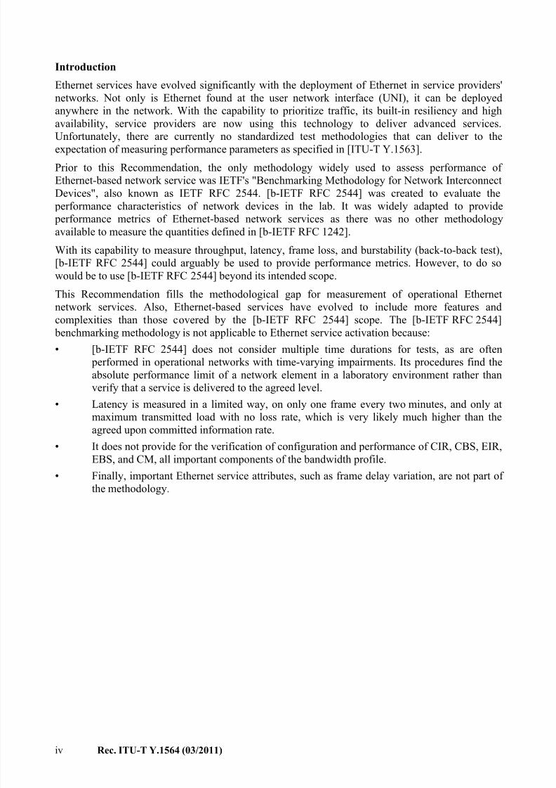
Introduction
Ethernet services have evolved significantly with the deployment of Ethernet in service providers'
networks. Not only is Ethernet found at the user network interface (UNI), it can be deployed
anywhere in the network. With the capability to prioritize traffic, its built-in resiliency and high
availability, service providers are now using this technology to deliver advanced services.
Unfortunately, there are currently no standardized test methodologies that can deliver to theexpectation of measuring performance parameters as specified in [ITU-T Y.1563].
Prior to this Recommendation, the only methodology widely used to assess performance of
Ethernet-based network service was IETF's "Benchmarking Methodology for Network Interconnect
Devices", also known as IETF RFC 2544. [b-IETF RFC 2544] was created to evaluate the
performance characteristics of network devices in the lab. It was widely adapted to provide
performance metrics of Ethernet-based network services as there was no other methodology
available to measure the quantities defined in [b-IETF RFC 1242].
With its capability to measure throughput, latency, frame loss, and burstability (back-to-back test),
[b-IETF RFC 2544] could arguably be used to provide performance metrics. However, to do so
would be to use [b-IETF RFC 2544] beyond its intended scope.
This Recommendation fills the methodological gap for measurement of operational Ethernet
network services. Also, Ethernet-based services have evolved to include more features and
complexities than those covered by the [b-IETF RFC 2544] scope. The [b-IETF RFC 2544]
benchmarking methodology is not applicable to Ethernet service activation because:
• [b-IETF RFC 2544] does not consider multiple time durations for tests, as are often
performed in operational networks with time-varying impairments. Its procedures find the
absolute performance limit of a network element in a laboratory environment rather than
verify that a service is delivered to the agreed level.
• Latency is measured in a limited way, on only one frame every two minutes, and only at
maximum transmitted load with no loss rate, which is very likely much higher than theagreed upon committed information rate.
• It does not provide for the verification of configuration and performance of CIR, CBS, EIR,
EBS, and CM, all important components of the bandwidth profile.
• Finally, important Ethernet service attributes, such as frame delay variation, are not part of
the methodology.
7/30/2019 T-REC-Y.1564-201103-I!!PDF-E
http://slidepdf.com/reader/full/t-rec-y1564-201103-ipdf-e 7/38
Rec. ITU-T Y.1564 (03/2011) 1
Recommendation ITU-T Y.1564
Ethernet service activation test methodology
1 Scope
This Recommendation defines an out-of-service test methodology to assess the proper configurationand performance of an Ethernet service prior to customer notification and delivery. The test
methodology applies to point-to-point and point-to-multipoint connectivity (using a pair-wise
configuration) in the Ethernet layer, and to the network portions that provide or contribute to the
provisioning of such services. This Recommendation does not define Ethernet network architectures
or services, but defines a methodology to test Ethernet-based services at the service activation stage.
In particular, it addresses testing out of the scope of [b-IETF RFC 2544] methods, as listed above.
This Recommendation assumes dedicated test equipment in the test methodology. It is understood
that this test methodology may be implemented as a test function inside of a network element.
2 References
The following ITU-T Recommendations and other references contain provisions which, through
reference in this text, constitute provisions of this Recommendation. At the time of publication, the
editions indicated were valid. All Recommendations and other references are subject to revision;
users of this Recommendation are therefore encouraged to investigate the possibility of applying the
most recent edition of the Recommendations and other references listed below. A list of the
currently valid ITU-T Recommendations is regularly published. The reference to a document within
this Recommendation does not give it, as a stand-alone document, the status of a Recommendation.
[ITU-T G.8010] Recommendation ITU-T G.8010/Y.1306 (2004), Architecture of Ethernet
layer networks, plus Amendment 1 (2006) and Amendment 2 (2010).
[ITU-T G.8011] Recommendation ITU-T G.8011/Y.1307 (2009), Ethernet service
characteristics.
[ITU-T G.8011.1] Recommendation ITU-T G.8011.1/Y.1307.1 (2009), Ethernet private line
service.
[ITU-T G.8011.2] Recommendation ITU-T G.8011.2/Y.1307.2 (2009), Ethernet virtual
private line service.
[ITU-T G.8012] Recommendation ITU-T G.8012/Y.1308 (2004), Ethernet UNI and
Ethernet NNI, plus Amendment 1 (2006).
[ITU-T M.2110] Recommendation ITU-T M.2110 (2002), Bringing into serviceinternational multi-operator paths, sections and transmission systems.
[ITU-T Y.1543] Recommendation ITU-T Y.1543 (2007), Measurements in IP networks for
inter-domain performance assessment .
[ITU-T Y.1563] Recommendation ITU-T Y.1563 (2009), Ethernet frame transfer and
availability performance, plus Amendment 1 (2009).
[ITU-T Y.1730] Recommendation ITU-T Y.1730 (2004), Requirements for OAM functions
in Ethernet-based networks and Ethernet services.
[ITU-T Y.1731] Recommendation ITU-T Y.1731 (2008), OAM functions and mechanisms
for Ethernet based networks, plus Amendment 1 (2010).[IEEE 802.1Q] IEEE 802.1Q-2003, IEEE Standards for Local and Metropolitan Area
Networks – Virtual Bridged Local Area Networks.
7/30/2019 T-REC-Y.1564-201103-I!!PDF-E
http://slidepdf.com/reader/full/t-rec-y1564-201103-ipdf-e 8/38
2 Rec. ITU-T Y.1564 (03/2011)
[MEF 10.2] Technical Specification MEF 10.2 (2009), Ethernet Services Attributes,
phase 2.
3 Definitions
3.1 Terms defined elsewhere
None.
3.2 Terms defined in this Recommendation
This Recommendation defines the following terms:
3.2.1 Ethernet virtual connection (EVC) (derived from [MEF 10.2]: An association of two or
more user network interfaces (UNIs) that limits the exchange of service frames between these
interfaces.
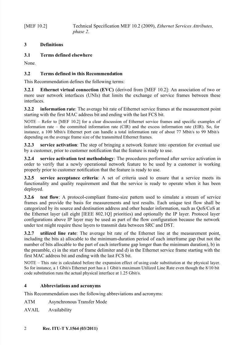
3.2.2 information rate: The average bit rate of Ethernet service frames at the measurement point
starting with the first MAC address bit and ending with the last FCS bit.
NOTE – Refer to [MEF 10.2] for a clear discussion of Ethernet service frames and specific examples of information rate – the committed information rate (CIR) and the excess information rate (EIR). So, for
instance, a 100 Mbit/s Ethernet port can handle a total information rate of about 77 Mbit/s to 99 Mbit/s
depending on the average frame size of the transmitted Ethernet frames.
3.2.3 service activation: The step of bringing a network feature into operation for eventual use
by a customer, prior to customer notification that the feature is ready to use.
3.2.4 service activation test methodology: The procedures performed after service activation in
order to verify that a newly operational network feature to be used by a customer is working
properly prior to customer notification that the feature is ready to use.
3.2.5 service acceptance criteria: A set of criteria used to ensure that a service meets its
functionality and quality requirement and that the service is ready to operate when it has been
deployed.
3.2.6 test flow: A protocol-compliant frame-size pattern used to simulate a stream of service
frames and provide the basis for measurements and test results. Each unique test flow shall be
categorized by its source and destination address and other header information, such as QoS/CoS at
the Ethernet layer (all eight [IEEE 802.1Q] priorities) and optionally the IP layer. Protocol layer
configurations above IP layer may be used as part of the flow configuration because the network
under test might require these layers to transmit data between SRC and DST.
3.2.7 utilized line rate: The average bit rate of the Ethernet line at the measurement point,
including the bits a) allocable to the minimum-duration period of each interframe gap (but not the
number of bits allocable to the part of each interframe gap longer than the minimum duration), b) in
the preamble, c) in the start of frame delimiter and d) in the Ethernet service frame starting with the
first MAC address bit and ending with the last FCS bit.
NOTE – This rate is calculated before the expansion effect of using code substitution at the physical layer.
So for instance, a 1 Gbit/s Ethernet port has a 1 Gbit/s maximum Utilized Line Rate even though the 8/10 bit
code substitution runs the actual physical interface at 1.25 Gbit/s.
4 Abbreviations and acronyms
This Recommendation uses the following abbreviations and acronyms:
ATM Asynchronous Transfer Mode
AVAIL Availability
7/30/2019 T-REC-Y.1564-201103-I!!PDF-E
http://slidepdf.com/reader/full/t-rec-y1564-201103-ipdf-e 9/38
Rec. ITU-T Y.1564 (03/2011) 3
CBS Committed Burst Size
CE Customer Edge
CF Coupling Flag
CIR Committed Information Rate
CM Colour ModeCoS Class of Service
DST Destination CE
EBS Excess Burst Size
EIR Excess Information Rate
EL Exchange Link
EMIX Ethernet Mix
ENNI External Network-to-Network Interface
ETH Ethernet MAC layer network
ETY Ethernet physical layer network
EVC Ethernet Virtual Connection
FCS Frame Check Sequence
FDV Frame Delay Variation
FL Frame Loss
FLR Frame Loss Ratio
FRE Frame Reference EventFTD Frame Transfer Delay
GPS Global Positioning System
IMIX Internet Mix
IP Internet Protocol
IR Information Rate
LACP Link Aggregation Control Protocol
LAN Local Area Network
MAC Medium Access Control
MP Measurement Point
MPLS MultiProtocol Label Switching
MTU Maximum Transmission Unit
NID Network Interface Device
NNI Network to Network Interface
NS Network Section
NSE Network Section EnsembleOAM Operation, Administration and Maintenance
OTN Optical Transport Network
7/30/2019 T-REC-Y.1564-201103-I!!PDF-E
http://slidepdf.com/reader/full/t-rec-y1564-201103-ipdf-e 10/38
4 Rec. ITU-T Y.1564 (03/2011)
PDH Plesiochronous Digital Hierarchy
PE Provider Edge
QoS Quality of Service
SAC Service Acceptance Criteria
SDH Synchronous Digital HierarchySLA Service Level Agreement
SRC Source CE
TCP Transmission Control Protocol
ToD Time of Day
UDP User Datagram Protocol
ULR Utilized Line Rate
UNI User Network Interface
UNI-C UNI – Customer
UNI-N UNI – Network
VLAN Virtual LAN
5 Conventions
This Recommendation uses the following terms to indicate requirement levels:
• MUST, SHALL, or REQUIRED means that the specification is a mandatory requirement
for test functions that claim compliance with this Recommendation.
• SHOULD means that there may exist valid reasons to avoid this specification, but thereasons need to be fully understood, and otherwise this is a strong suggestion for test
functions that claim compliance with this Recommendation.
• MAY means that the specification is truly optional, and need not be implemented in test
functions that claim compliance with this Recommendation.
6 Background on Ethernet network architecture and service attributes
This Recommendation does not define Ethernet network architectures or services, but defines a
methodology to test Ethernet-based services at the service activation stage. To provide some
background to the user, an overview of Ethernet network architecture and related service attributes
will be covered in this clause.
As the methodology relates to the performance model defined in [ITU-T Y.1563], the network
architecture it defines is used. From a service attributes perspective (i.e., CIR, EIR, etc.), there is no
reference to any service attributes in [ITU-T Y.1563], therefore the ones presented in the ITU-T
G.8011 family of Recommendations will be used.
6.1 Ethernet network architecture
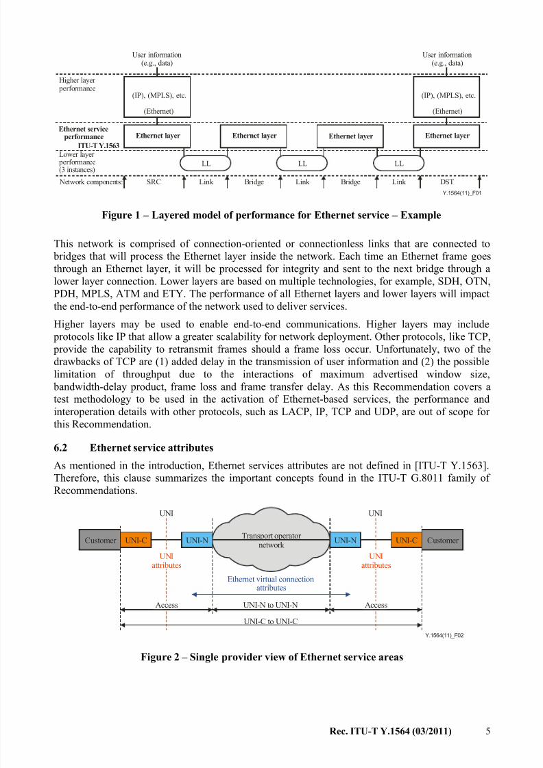
As illustrated in Figure 1, based on Figure 2 of [ITU-T Y.1563], Ethernet services are delivered
through a layered architecture. User information will be transported over a higher layer (usually IP),
that will then be encapsulated in an Ethernet layer to finally be transmitted across a network to a
destination. To provide an end-to-end transfer of user information, the higher layer at the source CEwill use the Ethernet layer to access the network. The Ethernet layer has end-to-end significance
only for a pair of source and destination MAC addresses.
7/30/2019 T-REC-Y.1564-201103-I!!PDF-E
http://slidepdf.com/reader/full/t-rec-y1564-201103-ipdf-e 11/38
Rec. ITU-T Y.1564 (03/2011) 5
Y.1564(11)_F01
Higher layer performance
User information(e.g., data)
(Ethernet)
Ethernet serviceperformance
ITU-T Y.1563Ethernet layer
Lower layer performance(3 instances)
Network components: SRC Link
LL LL
Link Bridge Bridge
Ethernet layer Ethernet layer Ethernet layer
LL
Link DST
(Ethernet)
User information(e.g., data)
(IP), (MPLS), etc.(IP), (MPLS), etc.
Figure 1 – Layered model of performance for Ethernet service – Example
This network is comprised of connection-oriented or connectionless links that are connected to
bridges that will process the Ethernet layer inside the network. Each time an Ethernet frame goes
through an Ethernet layer, it will be processed for integrity and sent to the next bridge through alower layer connection. Lower layers are based on multiple technologies, for example, SDH, OTN,
PDH, MPLS, ATM and ETY. The performance of all Ethernet layers and lower layers will impact
the end-to-end performance of the network used to deliver services.
Higher layers may be used to enable end-to-end communications. Higher layers may include
protocols like IP that allow a greater scalability for network deployment. Other protocols, like TCP,
provide the capability to retransmit frames should a frame loss occur. Unfortunately, two of the
drawbacks of TCP are (1) added delay in the transmission of user information and (2) the possible
limitation of throughput due to the interactions of maximum advertised window size,
bandwidth-delay product, frame loss and frame transfer delay. As this Recommendation covers a
test methodology to be used in the activation of Ethernet-based services, the performance andinteroperation details with other protocols, such as LACP, IP, TCP and UDP, are out of scope for
this Recommendation.
6.2 Ethernet service attributes
As mentioned in the introduction, Ethernet services attributes are not defined in [ITU-T Y.1563].
Therefore, this clause summarizes the important concepts found in the ITU-T G.8011 family of
Recommendations.
Y.1564(11)_F02
Customer Customer UNI-C UNI-C
UNI UNI
Transport operator network
Ethernet virtual connectionattributes
UNI-N to UNI-N
UNI-C to UNI-C
Access Access
UNIattributes
UNIattributes
UNI-N UNI-N
Figure 2 – Single provider view of Ethernet service areas
7/30/2019 T-REC-Y.1564-201103-I!!PDF-E
http://slidepdf.com/reader/full/t-rec-y1564-201103-ipdf-e 12/38
6 Rec. ITU-T Y.1564 (03/2011)
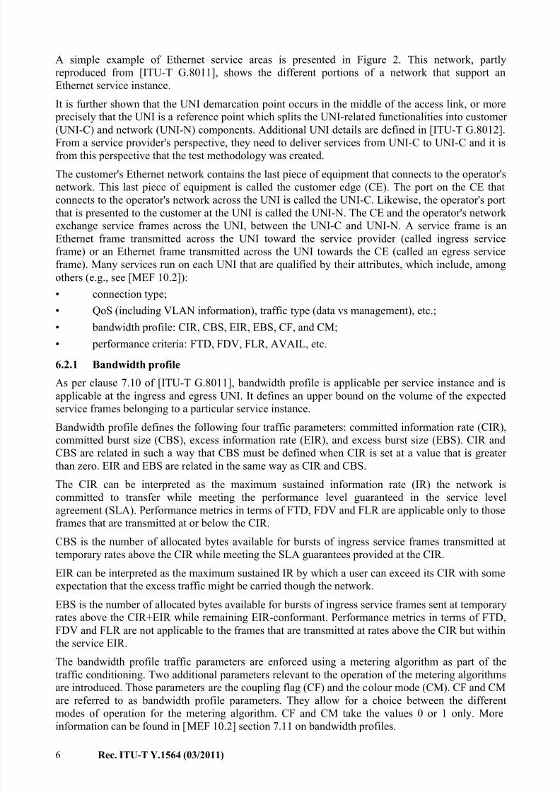
A simple example of Ethernet service areas is presented in Figure 2. This network, partly
reproduced from [ITU-T G.8011], shows the different portions of a network that support an
Ethernet service instance.
It is further shown that the UNI demarcation point occurs in the middle of the access link, or more
precisely that the UNI is a reference point which splits the UNI-related functionalities into customer
(UNI-C) and network (UNI-N) components. Additional UNI details are defined in [ITU-T G.8012].
From a service provider's perspective, they need to deliver services from UNI-C to UNI-C and it isfrom this perspective that the test methodology was created.
The customer's Ethernet network contains the last piece of equipment that connects to the operator's
network. This last piece of equipment is called the customer edge (CE). The port on the CE that
connects to the operator's network across the UNI is called the UNI-C. Likewise, the operator's port
that is presented to the customer at the UNI is called the UNI-N. The CE and the operator's network
exchange service frames across the UNI, between the UNI-C and UNI-N. A service frame is an
Ethernet frame transmitted across the UNI toward the service provider (called ingress service
frame) or an Ethernet frame transmitted across the UNI towards the CE (called an egress service
frame). Many services run on each UNI that are qualified by their attributes, which include, among
others (e.g., see [MEF 10.2]):• connection type;
• QoS (including VLAN information), traffic type (data vs management), etc.;
• bandwidth profile: CIR, CBS, EIR, EBS, CF, and CM;
• performance criteria: FTD, FDV, FLR, AVAIL, etc.
6.2.1 Bandwidth profile
As per clause 7.10 of [ITU-T G.8011], bandwidth profile is applicable per service instance and is
applicable at the ingress and egress UNI. It defines an upper bound on the volume of the expected
service frames belonging to a particular service instance.
Bandwidth profile defines the following four traffic parameters: committed information rate (CIR),
committed burst size (CBS), excess information rate (EIR), and excess burst size (EBS). CIR and
CBS are related in such a way that CBS must be defined when CIR is set at a value that is greater
than zero. EIR and EBS are related in the same way as CIR and CBS.
The CIR can be interpreted as the maximum sustained information rate (IR) the network is
committed to transfer while meeting the performance level guaranteed in the service level
agreement (SLA). Performance metrics in terms of FTD, FDV and FLR are applicable only to those
frames that are transmitted at or below the CIR.
CBS is the number of allocated bytes available for bursts of ingress service frames transmitted at
temporary rates above the CIR while meeting the SLA guarantees provided at the CIR.
EIR can be interpreted as the maximum sustained IR by which a user can exceed its CIR with some
expectation that the excess traffic might be carried though the network.
EBS is the number of allocated bytes available for bursts of ingress service frames sent at temporary
rates above the CIR+EIR while remaining EIR-conformant. Performance metrics in terms of FTD,
FDV and FLR are not applicable to the frames that are transmitted at rates above the CIR but within
the service EIR.
The bandwidth profile traffic parameters are enforced using a metering algorithm as part of the
traffic conditioning. Two additional parameters relevant to the operation of the metering algorithms
are introduced. Those parameters are the coupling flag (CF) and the colour mode (CM). CF and CM
are referred to as bandwidth profile parameters. They allow for a choice between the different
modes of operation for the metering algorithm. CF and CM take the values 0 or 1 only. More
information can be found in [MEF 10.2] section 7.11 on bandwidth profiles.
7/30/2019 T-REC-Y.1564-201103-I!!PDF-E
http://slidepdf.com/reader/full/t-rec-y1564-201103-ipdf-e 13/38
Rec. ITU-T Y.1564 (03/2011) 7
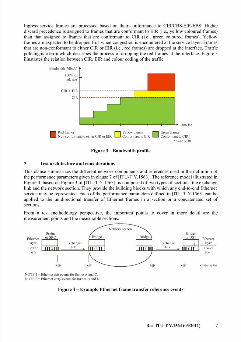
Ingress service frames are processed based on their conformance to CIR/CBS/EIR/EBS. Higher
discard precedence is assigned to frames that are conformant to EIR (i.e., yellow coloured frames)
than that assigned to frames that are conformant to CIR (i.e., green coloured frames). Yellow
frames are expected to be dropped first when congestion is encountered at the service layer. Frames
that are non-conformant to either CIR or EIR (i.e., red frames) are dropped at the interface. Traffic
policing is a term which describes the process of dropping the red frames at the interface. Figure 3
illustrates the relation between CIR, EIR and colour coding of the traffic.
Y.1564(11)_F03
Red frames Non-conformant to either CIR or EIR
− Yellow frames −Conformant to EIR
Green frames −Conformant to CIR
Bandwidth (Mbit/s)
100 of
link rate
CIR EIR
CIR
Time (s)
Figure 3 – Bandwidth profile
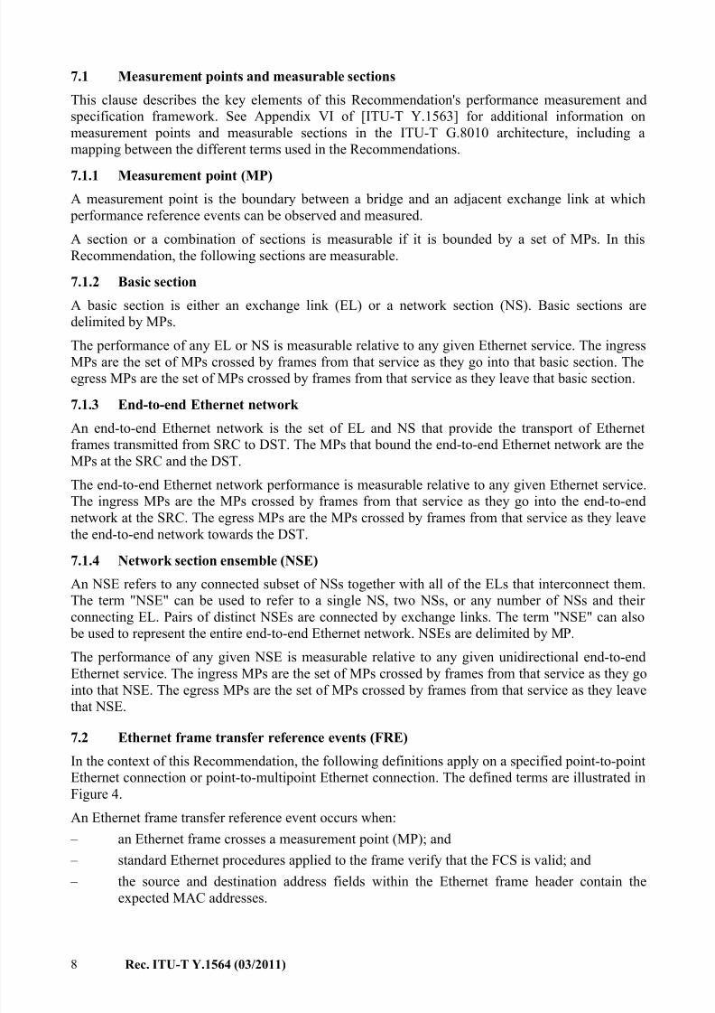
7 Test architecture and considerations
This clause summarizes the different network components and references used in the definition of
the performance parameters given in clause 7 of [ITU-T Y.1563]. The reference model illustrated in
Figure 4, based on Figure 3 of [ITU-T Y.1563], is composed of two types of sections: the exchange
link and the network section. They provide the building blocks with which any end-to-end Ethernet
service may be represented. Each of the performance parameters defined in [ITU-T Y.1563] can be
applied to the unidirectional transfer of Ethernet frames in a section or a concatenated set of
sections.
From a test methodology perspective, the important points to cover in more detail are the
measurement points and the measurable sections.
Y.1564(11)_F04
Bridgeor SRC
Exchangelink
Bridge
Network section
Bridge
Exchangelink
Bridgeor DST
Ethernetlayer
Lower layer
Ethernetlayer
Lower layer
MP MP MP MP
A B C D
NOTE 1 Ethernet exit events for frames A and C.
NOTE 2 Ethernet entry events for frames B and D.
−
−
Figure 4 – Example Ethernet frame transfer reference events
7/30/2019 T-REC-Y.1564-201103-I!!PDF-E
http://slidepdf.com/reader/full/t-rec-y1564-201103-ipdf-e 14/38
8 Rec. ITU-T Y.1564 (03/2011)
7.1 Measurement points and measurable sections
This clause describes the key elements of this Recommendation's performance measurement and
specification framework. See Appendix VI of [ITU-T Y.1563] for additional information on
measurement points and measurable sections in the ITU-T G.8010 architecture, including a
mapping between the different terms used in the Recommendations.
7.1.1 Measurement point (MP)
A measurement point is the boundary between a bridge and an adjacent exchange link at which
performance reference events can be observed and measured.
A section or a combination of sections is measurable if it is bounded by a set of MPs. In this
Recommendation, the following sections are measurable.
7.1.2 Basic section
A basic section is either an exchange link (EL) or a network section (NS). Basic sections are
delimited by MPs.
The performance of any EL or NS is measurable relative to any given Ethernet service. The ingress
MPs are the set of MPs crossed by frames from that service as they go into that basic section. The
egress MPs are the set of MPs crossed by frames from that service as they leave that basic section.
7.1.3 End-to-end Ethernet network
An end-to-end Ethernet network is the set of EL and NS that provide the transport of Ethernet
frames transmitted from SRC to DST. The MPs that bound the end-to-end Ethernet network are the
MPs at the SRC and the DST.
The end-to-end Ethernet network performance is measurable relative to any given Ethernet service.
The ingress MPs are the MPs crossed by frames from that service as they go into the end-to-end
network at the SRC. The egress MPs are the MPs crossed by frames from that service as they leave
the end-to-end network towards the DST.
7.1.4 Network section ensemble (NSE)
An NSE refers to any connected subset of NSs together with all of the ELs that interconnect them.
The term "NSE" can be used to refer to a single NS, two NSs, or any number of NSs and their
connecting EL. Pairs of distinct NSEs are connected by exchange links. The term "NSE" can also
be used to represent the entire end-to-end Ethernet network. NSEs are delimited by MP.
The performance of any given NSE is measurable relative to any given unidirectional end-to-end
Ethernet service. The ingress MPs are the set of MPs crossed by frames from that service as they go
into that NSE. The egress MPs are the set of MPs crossed by frames from that service as they leave
that NSE.
7.2 Ethernet frame transfer reference events (FRE)
In the context of this Recommendation, the following definitions apply on a specified point-to-point
Ethernet connection or point-to-multipoint Ethernet connection. The defined terms are illustrated in
Figure 4.
An Ethernet frame transfer reference event occurs when:
– an Ethernet frame crosses a measurement point (MP); and
– standard Ethernet procedures applied to the frame verify that the FCS is valid; and
– the source and destination address fields within the Ethernet frame header contain theexpected MAC addresses.
7/30/2019 T-REC-Y.1564-201103-I!!PDF-E
http://slidepdf.com/reader/full/t-rec-y1564-201103-ipdf-e 15/38
Rec. ITU-T Y.1564 (03/2011) 9
Four types of Ethernet frame transfer reference events are defined:
7.2.1 Ethernet frame entry event into an end station
An Ethernet frame transfer entry event into a bridge occurs when an Ethernet frame crosses a MP
entering a bridge (PE or DST) from the attached EL.
7.2.2 Ethernet frame exit event from an end station
An Ethernet frame transfer exit event from a bridge occurs when an Ethernet frame crosses a MP
exiting a bridge (PE or SRC) into the attached EL.
7.2.3 Ethernet frame ingress event into a basic section or NSE
An Ethernet frame transfer ingress event into a basic section occurs when an Ethernet frame crosses
an ingress MP into a basic section.
7.2.4 Ethernet frame egress event from a basic section or NSE
An Ethernet frame transfer egress event from a basic section occurs when an Ethernet frame crosses
an egress MP out of a basic section.
NOTE 1 – Ethernet frame entry and exit events always represent, respectively, entry into and exit from an
end station (bridge, SRC or DST). Ethernet frame ingress events and egress events always represent ingress
into and egress from a section or an NSE. To illustrate this point, note that an ingress event into an EL
follows from an exit event from the preceding bridge, while an ingress event into an NS is an entry event
because, by definition, NSs always have end stations (bridge, SRC or DST) at their edges.
NOTE 2 – For practical measurement purposes, Ethernet frame transfer reference events need not be
observed within the MAC layer of the end station. Instead, the time of occurrence of these reference events
can be approximated by observing the Ethernet frames crossing an associated physical interface. This
physical interface should, however, be as near as possible to the desired MP. In cases where reference events
are monitored at a physical interface, the time of occurrence of an exit event from an end station is
approximated by the observation of the first bit of the Ethernet frame coming from the end station or test
equipment. The time of occurrence of an entry event into an end station is approximated by the observationof the last bit of the Ethernet frame going to the end station or test equipment.
7.2.5 In-order and reordered Ethernet frame outcomes
The definition of these Ethernet frame outcomes requires some background discussion. In-order
frame delivery is a property of successful frame transfer attempts, where the sending frame order is
preserved on arrival at the destination (or measurement point). Arrival order is determined by the
position relative to other frames of interest, though the extent to which a given frame has been
reordered may be quantified in the units of position, time and payload byte distances.
A reordered frame performance parameter is relevant for most applications, especially when
assessing network support for real-time media streams, owing to their finite ability to restore order or the performance implications of a lack of that capability. Frames usually contain some unique
identifier applied at the SRC, sometimes assumed to be a sequence number, so this number or other
information (such as time stamps from the MP0) is the reference for the original order at the source.
The evaluation of arrival order also requires the ability to determine which specific frame is the
"next expected" frame, and this is greatly simplified with sequence numbers that are consecutive
increasing integers.
Assuming that sequence numbers are used for order verification, an in-order frame outcome occurs
when a single Ethernet frame reference event at a permissible egress measurement point results in
the following:
– The frame has a sequence number greater than or equal to the next expected frame value.
After this sequence number comparison is complete, the next expected value is increased to
the next number higher than the number in the just-received frame.
7/30/2019 T-REC-Y.1564-201103-I!!PDF-E
http://slidepdf.com/reader/full/t-rec-y1564-201103-ipdf-e 16/38
10 Rec. ITU-T Y.1564 (03/2011)
Assuming sequence numbers are used for order verification, a reordered or out-of-order frame
outcome occurs when a single Ethernet frame reference event at a permissible egress measurement
point results in the following:
– The frame has a sequence number lower than the next expected frame value, and therefore
the frame is reordered. The next expected value does not change after this sequence number
comparison.
Reordered and out-of-order frames outcome are an optional measurement in this Recommendation.
7.3 Test architecture considerations
This Recommendation explicitly uses the terms "test equipment" or "test instrument" in the test
methodology. It is understood that this test methodology MAY be implemented as a test function
inside a network element.
Compliant implementations of this methodology perform tests between two test instruments
connected at different MPs in the network. When measuring an EVC as depicted in Figure 2, the
test instruments will be connected to the service at the UNI, which represent the MPs. As per
[ITU-T Y.1563], these performance measurements are performed in a one-way fashion, whichmeans that performance parameters are measured separately in each direction.
There are unfortunately occasions when a dedicated testing resource is not available at one MP. For
example, the remote location equipment (DST) might not have all the test functionality found in a
test instrument. Some network elements found at the UNI will have the capability to loopback
traffic to a test instrument. As these network elements only have a logical loopback function, they
cannot be used in a one-way test.
When the ideal MPs described above cannot be accessed, or cannot be accessed without disrupting
service, then alternative measurement connectivity MAY be permissible as long as the users
understand and take steps to limit and quantify the measurement error.
One alternative measurement connection is to use a port loopback at one measurement point andmake all measurements in a round-trip connection performed by a single test instrument. There are
significant issues and limitations inherent to loopback connectivity, including:
• The network device performing the loopback may dominate the performance levels
measured. Overload testing on shared devices can affect the performance of other services.
• Unless symmetrical link speeds, traffic profile, QoS configuration, and frame routing are
present throughout the measured path, measurement errors can occur in any of the
performance parameters.
• It is unreliable and likely inaccurate to perform tests of excess traffic or bursts and attempt
to infer results for the return-from-loopback direction.
Where the precision of a one-way test is not needed, a logical loopback device can be used at one
end in combination with test equipment at the other end to provide a round-trip measurement of
service performance.
When the test instrument at the DST is replaced by a loopback function in a network device, then
only round-trip service acceptance criteria may be measured. Loopback measurements are primarily
intended for limited accuracy tests and for the convenience of maintenance forces, and cannot be
used to strictly validate SLA performance metrics, especially one-way metrics.
When a round-trip measurement is made by two test instruments to assess the performance
parameters and avoid clock synchronization requirements, some are not believed to be meaningful.
Performance parameters such as round-trip FTD or FLR have some use when the round-trip path issymmetrical with regard to delay and the loss is zero. Also, round-trip acceptance thresholds are
needed in addition to one-way thresholds. But items such as FDV and EIR are more problematic as
7/30/2019 T-REC-Y.1564-201103-I!!PDF-E
http://slidepdf.com/reader/full/t-rec-y1564-201103-ipdf-e 17/38
Rec. ITU-T Y.1564 (03/2011) 11
the test flow traverses the network twice and could be disproportionately affected by the
performance of the instrument providing the test loopback function or by network congestion in one
direction. FDV and EIR results for round-trip measurement could be studied further, but their
usefulness is questionable at this time.
Note that the network topology terminology of Figure 2 differs greatly from that of Figure 4. For
the purposes of this Recommendation, the associated UNIs at each end of the circuit shown in
Figure 2 are the two measurement points to be used to characterize end-to-end performance of theservice as suggested in Figure 4 and this clause.
7.4 Required test equipment capabilities
As part of the methodology, test flows must be configured to simulate user data encapsulated into
the different network layers so the traffic can be transported by the Ethernet network according to
the provisioned service attributes. The service may be provisioned to be port based, in which case
all flows from the UNI will be associated with a single bandwidth profile. Alternatively, the service
bandwidth profile may be provisioned to be attached to an individual VLAN at the UNI, with the
possibility of more than one VLAN having more than one bandwidth profile. Finally, bandwidth
profiles may be attached to individual CoS flows within a given VLAN. Referring to Figure 2, a testinstrument located at the UNI-N transmitting frames into the network section ensemble acts as the
SRC, and another test instrument located at the UNI-N on the other side of the network section
ensemble acts as the DST. Each service acceptance test requires testing to be configured in one or
more simultaneous test flows, which will be measured as an appropriate aggregate of test flows for
the service configuration test. Each test flow MUST have the capability to be configured for
QoS/CoS at the Ethernet layer (all eight [IEEE 802.1Q] priorities) and MAY be configured at the IP
layer. Protocol layer configurations above the IP layer MAY be used as part of the flow
configuration because the network under test might require these layers to transmit data between
SRC and DST.
Another capability required for one-way measurement is time of day (ToD) synchronization. One-
way measurements SHOULD use synchronization to align their measurement clocks. Without a
stable ToD reference (usually GPS based), a test instrument cannot accurately measure one-way
FTD from SRC to DST with sub-millisecond accuracy. Therefore, round-trip FTD MAY be used as
a service acceptance criteria. When the local clock has sufficiently stable frequency and long
term-accuracy characteristics over the test interval, one-way FDV and FLR performance MAY be
performed in accordance to the definition in [ITU-T Y.1543], where clock synchronization is
discussed in clause 6.6.
Additional discussion of clock synchronization may be found in clause 8.2 of [ITU-T Y.1731].
With good stability, users may find the quality of one-way measurements acceptable, despite using
temporarily non-synchronized clocks.
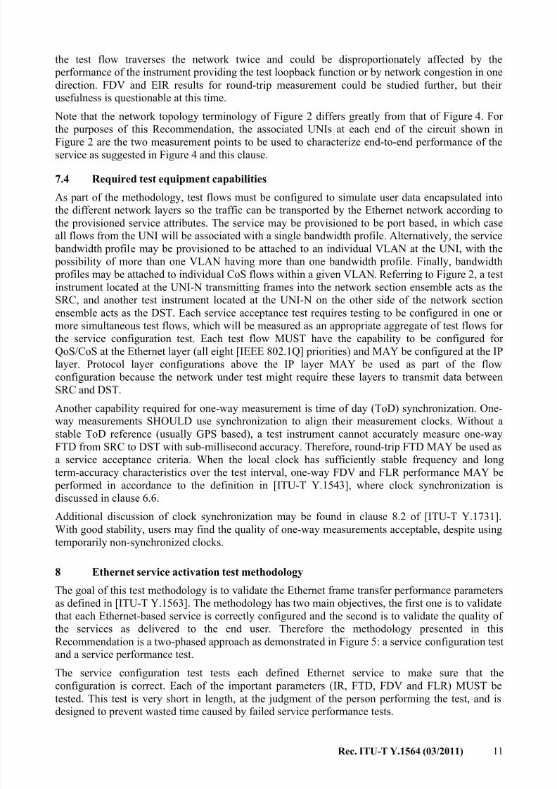
8 Ethernet service activation test methodology
The goal of this test methodology is to validate the Ethernet frame transfer performance parameters
as defined in [ITU-T Y.1563]. The methodology has two main objectives, the first one is to validate
that each Ethernet-based service is correctly configured and the second is to validate the quality of
the services as delivered to the end user. Therefore the methodology presented in this
Recommendation is a two-phased approach as demonstrated in Figure 5: a service configuration test
and a service performance test.
The service configuration test tests each defined Ethernet service to make sure that the
configuration is correct. Each of the important parameters (IR, FTD, FDV and FLR) MUST betested. This test is very short in length, at the judgment of the person performing the test, and is
designed to prevent wasted time caused by failed service performance tests.
7/30/2019 T-REC-Y.1564-201103-I!!PDF-E
http://slidepdf.com/reader/full/t-rec-y1564-201103-ipdf-e 18/38
12 Rec. ITU-T Y.1564 (03/2011)
The service performance test is conducted to validate the quality of the Ethernet services over a
medium to long time duration. The time duration is discussed in clause 8.2.1.
Y.1564(11)_F05
Enter test parameters
Start test
Serviceconfiguration
test
Pass
FailTroubleshoot
serviceconfiguration
Service
performancetest
Pass
Test completed
FailTroubleshoot
Ethernetservices
Figure 5 – High-level service activation test methodology
8.1 Service configuration test
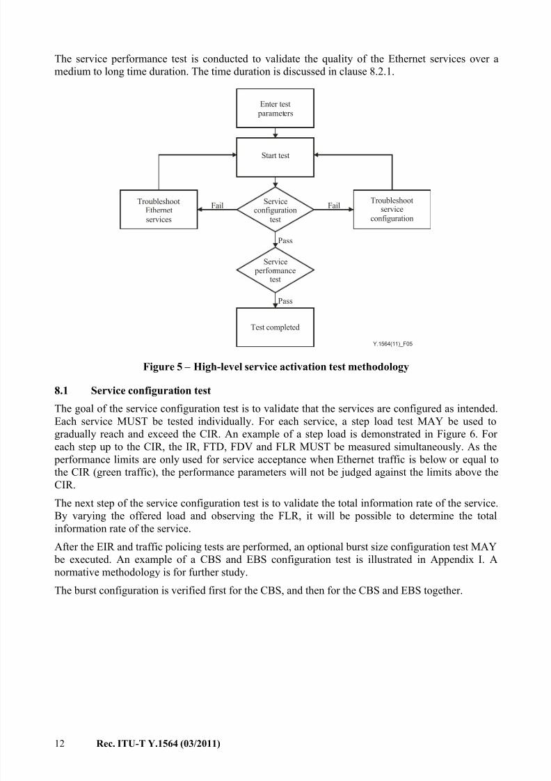
The goal of the service configuration test is to validate that the services are configured as intended.Each service MUST be tested individually. For each service, a step load test MAY be used to
gradually reach and exceed the CIR. An example of a step load is demonstrated in Figure 6. For
each step up to the CIR, the IR, FTD, FDV and FLR MUST be measured simultaneously. As the
performance limits are only used for service acceptance when Ethernet traffic is below or equal to
the CIR (green traffic), the performance parameters will not be judged against the limits above the
CIR.
The next step of the service configuration test is to validate the total information rate of the service.
By varying the offered load and observing the FLR, it will be possible to determine the total
information rate of the service.
After the EIR and traffic policing tests are performed, an optional burst size configuration test MAY be executed. An example of a CBS and EBS configuration test is illustrated in Appendix I. A
normative methodology is for further study.
The burst configuration is verified first for the CBS, and then for the CBS and EBS together.
7/30/2019 T-REC-Y.1564-201103-I!!PDF-E
http://slidepdf.com/reader/full/t-rec-y1564-201103-ipdf-e 19/38
Rec. ITU-T Y.1564 (03/2011) 13
Y.1564(11)_F06
Bandwidth (Mbit/s)
CIR EIR
25 EIR
CIR EIR
CIR
Time (s)
Level below whichSLA parameters
are verified
TX
Maximum informationrate threshold
1 to 60 seconds
Red frames
Non-conformant to either CIR or EIR
Yellow frames
Conformant to EIR
Green frames
Conformant to CIR
Figure 6 – Step-load test used in the service configuration test
NOTE 1 – The step load demonstrated in Figure 6 represents the transmission rate as would be seen at theoutput of the test instrument (denoted by the TX in the figure).
The test instruments SHOULD have the possibility of configuring the CIR, CBS, EIR, EBS, step
size and step duration for each service (test flow). The duration for each step size SHOULD be
configurable from at least 1 second up to 60 seconds. All equipment claiming compliance with this
Recommendation MUST provide the default values as per clause 8.3
NOTE 2 – Caution should be exercised when configuring the test time for the service configuration test to
make sure the traffic policer has enough time to be exercised. Low information rate combined with high
burst sizes require more time for the traffic policing to take effect. Guidance on test time is for further study.
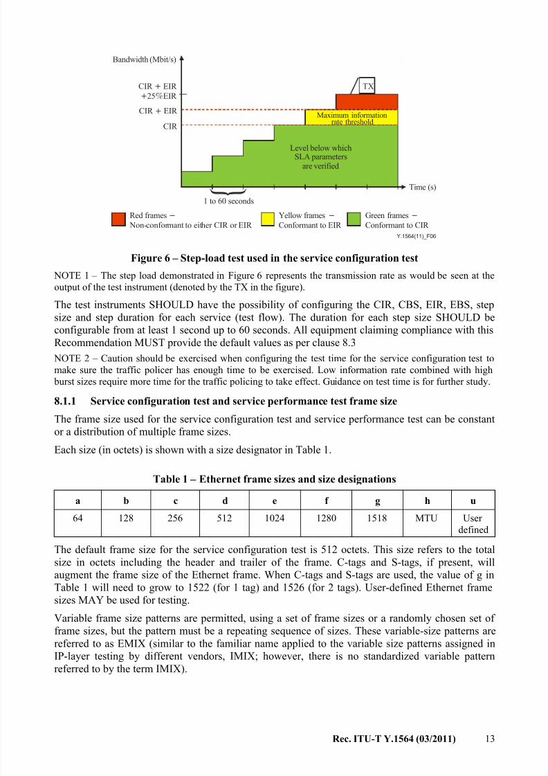
8.1.1 Service configuration test and service performance test frame size
The frame size used for the service configuration test and service performance test can be constant
or a distribution of multiple frame sizes.
Each size (in octets) is shown with a size designator in Table 1.
Table 1 – Ethernet frame sizes and size designations
a b c d e f g h u
64 128 256 512 1024 1280 1518 MTU User
defined
The default frame size for the service configuration test is 512 octets. This size refers to the total
size in octets including the header and trailer of the frame. C-tags and S-tags, if present, will
augment the frame size of the Ethernet frame. When C-tags and S-tags are used, the value of g in
Table 1 will need to grow to 1522 (for 1 tag) and 1526 (for 2 tags). User-defined Ethernet frame
sizes MAY be used for testing.
Variable frame size patterns are permitted, using a set of frame sizes or a randomly chosen set of
frame sizes, but the pattern must be a repeating sequence of sizes. These variable-size patterns are
referred to as EMIX (similar to the familiar name applied to the variable size patterns assigned in
IP-layer testing by different vendors, IMIX; however, there is no standardized variable pattern
referred to by the term IMIX).
7/30/2019 T-REC-Y.1564-201103-I!!PDF-E
http://slidepdf.com/reader/full/t-rec-y1564-201103-ipdf-e 20/38
14 Rec. ITU-T Y.1564 (03/2011)
EMIX patterns shall be specified by the size designator for each frame in the repeating pattern from
Table 1. For example, a five-frame repeating pattern can be specified as follows:
EMIX – ggeaa = 1518, 1518, 1024, 64, 64
The default pattern SHOULD be the sequence of sizes:
EMIX – abceg
8.1.2 Service configuration test procedure
The following steps provide the test procedure for verifying proper network configuration before
proceeding to the service performance test. Each of these tests MUST be run separately for each
service to be activated between two or more UNIs and the corresponding measurement points.
Utilized line rate and information rate MAY be used to define and report bandwidth profiles test
parameters, results or information in accordance with this Recommendation. To simplify this
Recommendation, only information rate will be used in the procedure that follows.
Here is a high level summary of the paragraphs to follow in this clause. Only one procedure
SHOULD be used from each of the five capitalized-letter subclauses below.
A. CIR configuration test, colour aware and non-colour aware:
A.1 Simple CIR validation (mandatory to implement, optional to perform).
A.2 Step load CIR test (mandatory to implement, optional to perform).
B. EIR configuration test:
B.1 Colour aware (mandatory to implement, optional to perform).
B.2 Non-colour aware (mandatory to implement, optional to perform).
C. Traffic policing test:
C.1 Colour aware (mandatory to implement, optional to perform).
C.2 Non-colour aware (mandatory to implement, optional to perform).
D. CBS configuration test, colour aware and non-colour aware (optional test to implement).
E. EBS configuration test (optional test to implement):
E.1 Colour aware and non-colour aware, CIR = 0.
E.2 Colour aware, CIR > 0.
E.3 Non-colour aware, CIR > 0.
A) CIR configuration test – Colour aware and non-colour aware
A.1) Simple CIR validation test
1. Configure test function CIR as target offered load rate, EIR, test duration, and framesize/pattern.
2. Transmit at the CIR. Frames SHOULD be transmitted at constant intervals, e.g., without
burstiness or interval variation. If interval variation is present, it should be proportional to
the size variation in the EMIX. Frames MAY be transmitted in units of IR bits per second,
although transmission rate measured in utilized line rate (ULR) bits per second is also
acceptable.
3. Measure the received IR, FLR, FTD and FDV. FLR SAC is the frame loss ratio limit as
specified in the SAC.
4. If the performance parameters are not within SAC limits, the user SHOULD troubleshoot
the problem. Investigate the issues, determine the possible configuration error and correct
the problem if necessary. Repeat the service configuration test from Step 2, or perform the
step load CIR test (A.2).
7/30/2019 T-REC-Y.1564-201103-I!!PDF-E
http://slidepdf.com/reader/full/t-rec-y1564-201103-ipdf-e 21/38
Rec. ITU-T Y.1564 (03/2011) 15
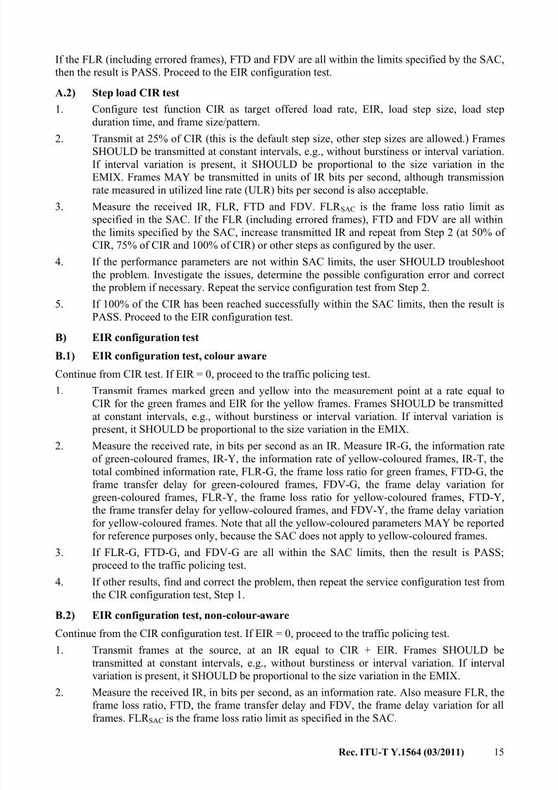
If the FLR (including errored frames), FTD and FDV are all within the limits specified by the SAC,
then the result is PASS. Proceed to the EIR configuration test.
A.2) Step load CIR test
1. Configure test function CIR as target offered load rate, EIR, load step size, load step
duration time, and frame size/pattern.
2. Transmit at 25% of CIR (this is the default step size, other step sizes are allowed.) FramesSHOULD be transmitted at constant intervals, e.g., without burstiness or interval variation.
If interval variation is present, it SHOULD be proportional to the size variation in the
EMIX. Frames MAY be transmitted in units of IR bits per second, although transmission
rate measured in utilized line rate (ULR) bits per second is also acceptable.
3. Measure the received IR, FLR, FTD and FDV. FLR SAC is the frame loss ratio limit as
specified in the SAC. If the FLR (including errored frames), FTD and FDV are all within
the limits specified by the SAC, increase transmitted IR and repeat from Step 2 (at 50% of
CIR, 75% of CIR and 100% of CIR) or other steps as configured by the user.
4. If the performance parameters are not within SAC limits, the user SHOULD troubleshoot
the problem. Investigate the issues, determine the possible configuration error and correctthe problem if necessary. Repeat the service configuration test from Step 2.
5. If 100% of the CIR has been reached successfully within the SAC limits, then the result is
PASS. Proceed to the EIR configuration test.
B) EIR configuration test
B.1) EIR configuration test, colour aware
Continue from CIR test. If EIR = 0, proceed to the traffic policing test.
1. Transmit frames marked green and yellow into the measurement point at a rate equal to
CIR for the green frames and EIR for the yellow frames. Frames SHOULD be transmitted
at constant intervals, e.g., without burstiness or interval variation. If interval variation is present, it SHOULD be proportional to the size variation in the EMIX.
2. Measure the received rate, in bits per second as an IR. Measure IR-G, the information rate
of green-coloured frames, IR-Y, the information rate of yellow-coloured frames, IR-T, the
total combined information rate, FLR-G, the frame loss ratio for green frames, FTD-G, the
frame transfer delay for green-coloured frames, FDV-G, the frame delay variation for
green-coloured frames, FLR-Y, the frame loss ratio for yellow-coloured frames, FTD-Y,
the frame transfer delay for yellow-coloured frames, and FDV-Y, the frame delay variation
for yellow-coloured frames. Note that all the yellow-coloured parameters MAY be reported
for reference purposes only, because the SAC does not apply to yellow-coloured frames.
3. If FLR-G, FTD-G, and FDV-G are all within the SAC limits, then the result is PASS; proceed to the traffic policing test.
4. If other results, find and correct the problem, then repeat the service configuration test from
the CIR configuration test, Step 1.
B.2) EIR configuration test, non-colour-aware
Continue from the CIR configuration test. If EIR = 0, proceed to the traffic policing test.
1. Transmit frames at the source, at an IR equal to CIR + EIR. Frames SHOULD be
transmitted at constant intervals, e.g., without burstiness or interval variation. If interval
variation is present, it SHOULD be proportional to the size variation in the EMIX.
2. Measure the received IR, in bits per second, as an information rate. Also measure FLR, theframe loss ratio, FTD, the frame transfer delay and FDV, the frame delay variation for all
frames. FLR SAC is the frame loss ratio limit as specified in the SAC.
7/30/2019 T-REC-Y.1564-201103-I!!PDF-E
http://slidepdf.com/reader/full/t-rec-y1564-201103-ipdf-e 22/38
16 Rec. ITU-T Y.1564 (03/2011)
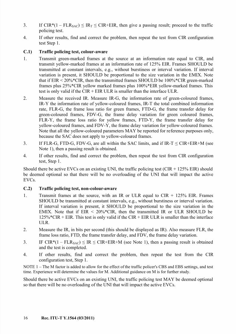
3. If CIR*(1 – FLR SAC) ≤ IR T ≤ CIR+EIR, then give a passing result; proceed to the traffic
policing test.
4. If other results, find and correct the problem, then repeat the test from CIR configuration
test Step 1.
C.1) Traffic policing test, colour-aware
1. Transmit green-marked frames at the source at an information rate equal to CIR, andtransmit yellow-marked frames at an information rate of 125% EIR. Frames SHOULD be
transmitted at constant intervals, e.g., without burstiness or interval variation. If interval
variation is present, it SHOULD be proportional to the size variation in the EMIX. Note
that if EIR < 20%*CIR, then the transmitted frames SHOULD be 100%*CIR green-marked
frames plus 25%*CIR yellow marked frames plus 100%*EIR yellow-marked frames. This
test is only valid if the CIR + EIR ULR is smaller than the interface ULR.
2. Measure the received IR. Measure IR-G, the information rate of green-coloured frames,
IR-Y the information rate of yellow-coloured frames, IR-T the total combined information
rate, FLR-G, the frame loss ratio for green frames, FTD-G, the frame transfer delay for
green-coloured frames, FDV-G, the frame delay variation for green coloured frames,
FLR-Y, the frame loss ratio for yellow frames, FTD-Y, the frame transfer delay for
yellow-coloured frames, and FDV-Y, the frame delay variation for yellow-coloured frames.
Note that all the yellow-coloured parameters MAY be reported for reference purposes only,
because the SAC does not apply to yellow-coloured frames.
3. If FLR-G, FTD-G, FDV-G, are all within the SAC limits, and if IR-T ≤ CIR+EIR+M (see
Note 1), then a passing result is obtained.
4. If other results, find and correct the problem, then repeat the test from CIR configuration
test, Step 1.
Should there be active EVCs on an existing UNI, the traffic policing test (CIR + 125% EIR) should
be deemed optional so that there will be no overloading of the UNI that will impact the activeEVCs.
C.2) Traffic policing test, non-colour-aware
1. Transmit frames at the source, with an IR or ULR equal to CIR + 125% EIR. Frames
SHOULD be transmitted at constant intervals, e.g., without burstiness or interval variation.
If interval variation is present, it SHOULD be proportional to the size variation in the
EMIX. Note that if EIR < 20%*CIR, then the transmitted IR or ULR SHOULD be
125%*CIR + EIR. This test is only valid if the CIR + EIR ULR is smaller than the interface
ULR.
2. Measure the IR, in bits per second (this should be displayed as IR). Also measure FLR, the
frame loss ratio, FTD, the frame transfer delay, and FDV, the frame delay variation.
3. IF CIR*(1 – FLR SAC) ≤ IR ≤ CIR+EIR+M (see Note 1), then a passing result is obtained
and the test is completed.
4. If other results, find and correct the problem, then repeat the test from the CIR
configuration test, Step 1.
NOTE 1 – The M factor is added to allow for the effect of the traffic policer's CBS and EBS settings, and test
time. Experience will determine the values for M. Additional guidance on M is for further study.
Should there be active EVCs on an existing UNI, the traffic policing test MAY be deemed optional
so that there will be no overloading of the UNI that will impact the active EVCs.
7/30/2019 T-REC-Y.1564-201103-I!!PDF-E
http://slidepdf.com/reader/full/t-rec-y1564-201103-ipdf-e 23/38
Rec. ITU-T Y.1564 (03/2011) 17
The following two tests which are still considered preliminary/experimental are included for
informational purposes only in Appendix I:
D) CBS configuration test, colour aware and non-colour aware
E) EBS configuration test
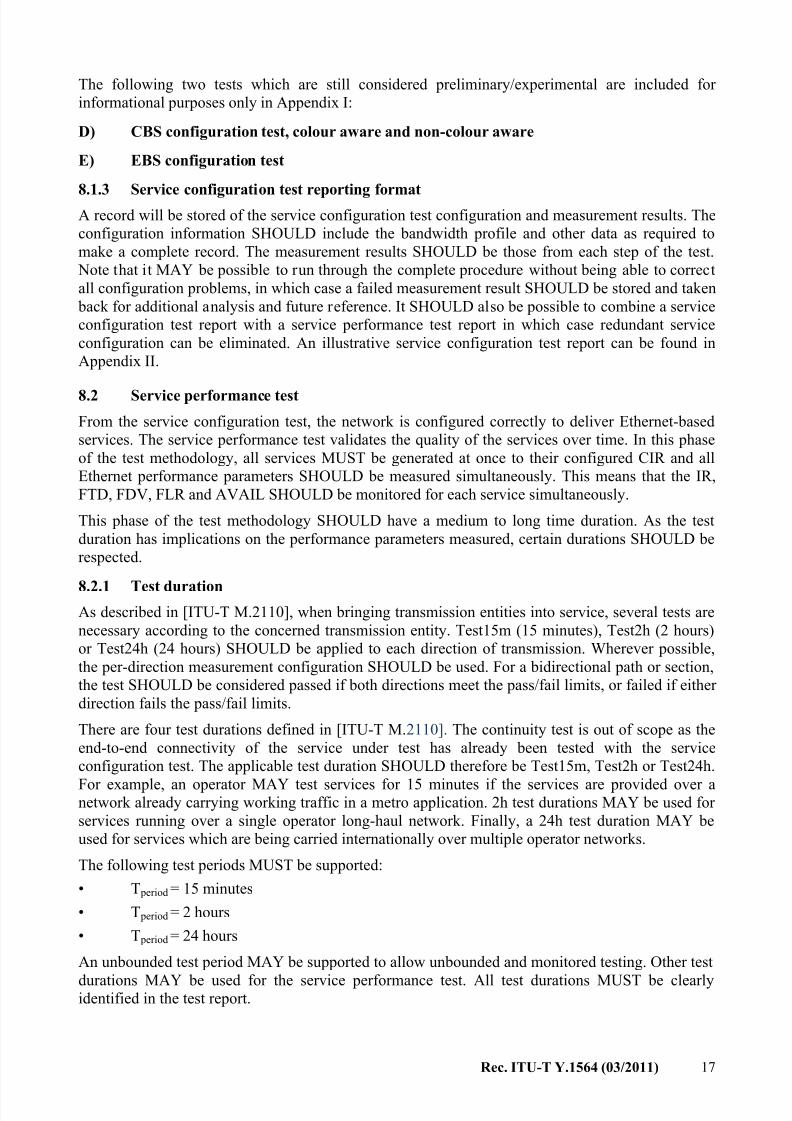
8.1.3 Service configuration test reporting formatA record will be stored of the service configuration test configuration and measurement results. The
configuration information SHOULD include the bandwidth profile and other data as required to
make a complete record. The measurement results SHOULD be those from each step of the test.
Note that it MAY be possible to run through the complete procedure without being able to correct
all configuration problems, in which case a failed measurement result SHOULD be stored and taken
back for additional analysis and future reference. It SHOULD also be possible to combine a service
configuration test report with a service performance test report in which case redundant service
configuration can be eliminated. An illustrative service configuration test report can be found in
Appendix II.
8.2 Service performance test
From the service configuration test, the network is configured correctly to deliver Ethernet-based
services. The service performance test validates the quality of the services over time. In this phase
of the test methodology, all services MUST be generated at once to their configured CIR and all
Ethernet performance parameters SHOULD be measured simultaneously. This means that the IR,
FTD, FDV, FLR and AVAIL SHOULD be monitored for each service simultaneously.
This phase of the test methodology SHOULD have a medium to long time duration. As the test
duration has implications on the performance parameters measured, certain durations SHOULD be
respected.
8.2.1 Test durationAs described in [ITU-T M.2110], when bringing transmission entities into service, several tests are
necessary according to the concerned transmission entity. Test15m (15 minutes), Test2h (2 hours)
or Test24h (24 hours) SHOULD be applied to each direction of transmission. Wherever possible,
the per-direction measurement configuration SHOULD be used. For a bidirectional path or section,
the test SHOULD be considered passed if both directions meet the pass/fail limits, or failed if either
direction fails the pass/fail limits.
There are four test durations defined in [ITU-T M.2110]. The continuity test is out of scope as the
end-to-end connectivity of the service under test has already been tested with the service
configuration test. The applicable test duration SHOULD therefore be Test15m, Test2h or Test24h.
For example, an operator MAY test services for 15 minutes if the services are provided over anetwork already carrying working traffic in a metro application. 2h test durations MAY be used for
services running over a single operator long-haul network. Finally, a 24h test duration MAY be
used for services which are being carried internationally over multiple operator networks.
The following test periods MUST be supported:
• T period = 15 minutes
• T period = 2 hours
• T period = 24 hours
An unbounded test period MAY be supported to allow unbounded and monitored testing. Other test
durations MAY be used for the service performance test. All test durations MUST be clearlyidentified in the test report.
7/30/2019 T-REC-Y.1564-201103-I!!PDF-E
http://slidepdf.com/reader/full/t-rec-y1564-201103-ipdf-e 24/38
18 Rec. ITU-T Y.1564 (03/2011)
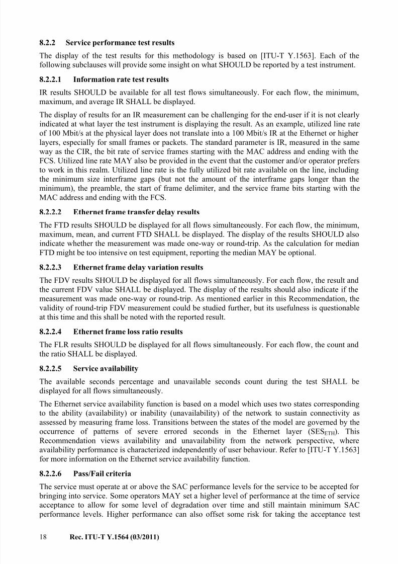
8.2.2 Service performance test results
The display of the test results for this methodology is based on [ITU-T Y.1563]. Each of the
following subclauses will provide some insight on what SHOULD be reported by a test instrument.
8.2.2.1 Information rate test results
IR results SHOULD be available for all test flows simultaneously. For each flow, the minimum,
maximum, and average IR SHALL be displayed.
The display of results for an IR measurement can be challenging for the end-user if it is not clearly
indicated at what layer the test instrument is displaying the result. As an example, utilized line rate
of 100 Mbit/s at the physical layer does not translate into a 100 Mbit/s IR at the Ethernet or higher
layers, especially for small frames or packets. The standard parameter is IR, measured in the same
way as the CIR, the bit rate of service frames starting with the MAC address and ending with the
FCS. Utilized line rate MAY also be provided in the event that the customer and/or operator prefers
to work in this realm. Utilized line rate is the fully utilized bit rate available on the line, including
the minimum size interframe gaps (but not the amount of the interframe gaps longer than the
minimum), the preamble, the start of frame delimiter, and the service frame bits starting with the
MAC address and ending with the FCS.
8.2.2.2 Ethernet frame transfer delay results
The FTD results SHOULD be displayed for all flows simultaneously. For each flow, the minimum,
maximum, mean, and current FTD SHALL be displayed. The display of the results SHOULD also
indicate whether the measurement was made one-way or round-trip. As the calculation for median
FTD might be too intensive on test equipment, reporting the median MAY be optional.
8.2.2.3 Ethernet frame delay variation results
The FDV results SHOULD be displayed for all flows simultaneously. For each flow, the result and
the current FDV value SHALL be displayed. The display of the results should also indicate if the
measurement was made one-way or round-trip. As mentioned earlier in this Recommendation, thevalidity of round-trip FDV measurement could be studied further, but its usefulness is questionable
at this time and this shall be noted with the reported result.
8.2.2.4 Ethernet frame loss ratio results
The FLR results SHOULD be displayed for all flows simultaneously. For each flow, the count and
the ratio SHALL be displayed.
8.2.2.5 Service availability
The available seconds percentage and unavailable seconds count during the test SHALL be
displayed for all flows simultaneously.
The Ethernet service availability function is based on a model which uses two states corresponding
to the ability (availability) or inability (unavailability) of the network to sustain connectivity as
assessed by measuring frame loss. Transitions between the states of the model are governed by the
occurrence of patterns of severe errored seconds in the Ethernet layer (SESETH). This
Recommendation views availability and unavailability from the network perspective, where
availability performance is characterized independently of user behaviour. Refer to [ITU-T Y.1563]
for more information on the Ethernet service availability function.
8.2.2.6 Pass/Fail criteria
The service must operate at or above the SAC performance levels for the service to be accepted for
bringing into service. Some operators MAY set a higher level of performance at the time of serviceacceptance to allow for some level of degradation over time and still maintain minimum SAC
performance levels. Higher performance can also offset some risk for taking the acceptance test
7/30/2019 T-REC-Y.1564-201103-I!!PDF-E
http://slidepdf.com/reader/full/t-rec-y1564-201103-ipdf-e 25/38
Rec. ITU-T Y.1564 (03/2011) 19
over a shorter interval. For instance, the availability limit may be set at a much higher level than
SAC or at exactly 100% during the acceptance measurement time. Also, if multiple operators are
working together to deliver a service, each operator MAY need to get a budget for the performance
for the particular link that the operator will provide, subject to negotiation among the cooperating
providers, so that the overall SAC is met for the end-to-end service for the end user.
8.2.2.7 Service performance test report format
A record will be stored of the service performance test configuration and measurement results. The
configuration information SHOULD include the bandwidth profile and other data as required to
make a complete record. If this report is printed or downloaded with the service configuration test,
then the configuration information SHOULD not be recorded twice, as long as it is the same for
both tests. An illustrative service performance test report can be found in Appendix II.
8.3 Test configuration
The test equipment SHALL allow the user to configure the following functionality to perform the
test (unless the word "optional" is fixed to the feature, in which case it is optional to provide the
feature):
a) UNI attributes:
Port speed: 10 Mbit/s, 100 Mbit/s, 10/100 Mbit/s Auto negotiate, 1 Gbit/s, 10 Gbit/s
Port type: Optional combination of the following: 10/100BASE-T, 100BASE-FX,
1000BASE-T, 1000BASE-X, 10GBASE-W, 10GBASE-R
NOTE – Port type and port speed might be found on multiple test equipments to cover all possibilities.
b) Number of services being tested (test equipment MUST support at least one).
c) Service attribute configurations for each service:
Bandwidth profile (CIR/CBS/EIR/EBS/CM/optional CF).
Service acceptance criteria (FLR, FTD, FDV, AVAIL).Maximum transmission unit size to test at (default 1518).
Traffic policing: On/Off.
d) Per flow test frame definitions – Destination MAC address, source MAC address, 0 or 1
VLAN ID/Priority tags, optional second VLAN ID for S-TAG, TAG protocol ID, PCP or
IP DSCP.
e) Per test flow frame size:
Fixed (64, 128, 256, 512, 1024, 1280, 1518, or MTU).
Optional EMIX (64, 128, 256, 512, 1024, 1280, 1518, MTU).
Other pattern sequences are acceptable according to operational preference.
f) Test time/steps for the service configuration test (at least 1 to 60 seconds per step, at least 1
to 4 steps, optional to fallback to lower speeds to debug failure after starting at full CIR)
and duration for the service performance test (choices provided at least for 15 minutes,
2 hours, and 24 hours).
8.4 Test connectivity considerations
This Recommendation explicitly uses test equipment to describe the test methodology. It is
understood that this test methodology MAY be implemented as a test function inside of a network
element.
7/30/2019 T-REC-Y.1564-201103-I!!PDF-E
http://slidepdf.com/reader/full/t-rec-y1564-201103-ipdf-e 26/38
20 Rec. ITU-T Y.1564 (03/2011)
As specified in clause 7.3, compliant implementations of this methodology SHOULD perform tests
between two test instruments connected at different UNIs in the network when measuring an EVC
as depicted in Figure 2. This is an intrusive test configuration that REQUIRES replacement of the
customer equipment connection with a connection to the test equipment.
Other test connections MAY be used when unavoidable, with the understanding that results that
differ from the compliant configuration are possible. Examples of such circumstances are discussed
below.
On occasion, a new service will need to be tested that is running on an Ethernet line that is already
carrying other in-service traffic. Care must be taken to avoid disrupting the in-service traffic while
the new measurement is made. If there is a NID at the UNI, the NID MAY offer a test access port
that can non-disruptively drop and insert traffic into the UNI while the other port is plugged in to
the customer edge equipment carrying live traffic.
Alternatively, the test equipment MAY have a mode where it is able with dual ports to pass traffic
through without disruption while dropping and inserting test flows toward the network or toward
the customer premises. Care should be used with this method, however, because merely plugging
the test equipment into the line will cause at least a momentary disruption to traffic, and if any
configuration errors are made in setting up the equipment, then the disruption may become
extended.
A final way to accomplish testing over an active service is to connect to the closest device to the
UNI that offers non-disruptive test access, such as a switch. It should be noted that in this case, the
user has an even larger burden to monitor the live traffic rates at the interface so that the test traffic
that is introduced does not overload the physical ability of the UNI to carry all the transmitted
frames.
Should there be active EVCs on an existing UNI, the traffic policing test MAY be deemed optional
so that there is no overloading of the UNI that will impact the active EVCs.
8.5 Availability considerations for testing
[ITU-T Y.1563] and [MEF 10.2] exclude unavailable time for the purposes of performance
parameter/attribute evaluation and comparison with objectives. This principle MUST be
implemented in test equipment/function, to ensure that they consistently measure performance and
the results compare favourably with other test equipment functions.
Availability was originally developed as an in-service monitoring performance parameter that
would be accumulated and reported in monthly intervals. Unavailable time shall not be used for the
purposes of SAC evaluation in service activation testing, beyond reporting the presence of
unavailability in the reported results (as in clause 8.2.2.5). However, the operator MAY choose to
include availability as a performance parameter with a limit that will drive a pass/fail result in the
service performance test. The test equipment SHOULD support availability testing and its optional
use as pass/fail criteria in the service performance test. The longer the test interval, the more
statistically relevant the availability parameter becomes.
Test equipment SHOULD display periods of unavailability that occur during testing so that the
operator can take action if desired.
7/30/2019 T-REC-Y.1564-201103-I!!PDF-E
http://slidepdf.com/reader/full/t-rec-y1564-201103-ipdf-e 27/38
Rec. ITU-T Y.1564 (03/2011) 21
8.6 Frame loss ratio and errored frame ratio
Errored frames are dropped by the network to prevent undesirable effects. Therefore, in most cases
it SHOULD be sufficient to examine the frame loss ratio in order to see if the service has provided
acceptable performance to the customer. However, in some cases such as microwave access links,
the access portion of the network MAY provide by far the highest source of errors. In this case,
frames egressing the network at the UNI MAY not be dropped if they are errored, particularly if a
NID is not installed at the UNI. When performing service activation testing, service providers MAYalso combine their frame error counts with their frame loss counts and require the sum of those
parameters to meet the FLR acceptance limits.
7/30/2019 T-REC-Y.1564-201103-I!!PDF-E
http://slidepdf.com/reader/full/t-rec-y1564-201103-ipdf-e 28/38
22 Rec. ITU-T Y.1564 (03/2011)
Appendix I
CBS and EBS test methodology
(This appendix does not form an integral part of this Recommendation.)
I.1 IntroductionThe two tests described below are still considered preliminary/experimental, and are therefore
included for informational purposes only.
The bandwidth profile contains attributes of committed burst size and excess burst size that some
service providers may wish to test at the time of service activation to verify proper attribute
configuration. These procedures may be inserted after completion of the traffic policing test step of
the service configuration test. As very little testing of CBS and EBS is documented in the
certification tests heretofore available in the industry, there is a clear need for appropriate methods
to use at the time of service activation. One such method is provided below, and verifies the
configuration of traffic policers that operate according to the bandwidth profile algorithm, as
defined in Figure 13 of [MEF 10.2].Some network element manufacturers may feel that alternative procedures may produce more
appropriate results, and such manufacturers are welcome to provide their procedures to ITU-T for
further review and study. Note that burst testing is most meaningful for high bandwidth Ethernet
user network interfaces that have a small fraction of the line capacity provisioned to carry customer
traffic. As the EIR or CIR grow to approach full line rate, the usefulness of burst testing declines,
and it can take significantly longer to perform a burst test according to these procedures. These
burst test procedures are designed to work best at committed and excess information rates up to
67% of maximum attainable information rate.
I.2 CBS test methodology
D) CBS configuration test – Colour aware and non-colour aware
1. If there is no CBS provisioned, proceed to the EBS test.
2. For procedural context, refer to [b-MEF 19], test case 36 and [MEF 10.2], Figure 13. The
value for time interval T of test case 36 and a single period of this test is chosen so that a
frame loss rate of 10% will occur if all frames that are sent through the associated
back-to-back burst are dropped by the network. F (tolerance variance) of test case 36 is
substituted by the FLR of the SAC or other lesser operator-chosen limit with exact
acceptance criteria as described in Step 5 below.
3. At the beginning of the CBS test, the transmitter turns off for the smallest amount of time
equal to or greater than 100%*CBS*8/CIR to initialize the measurement with the Bc CBStoken bucket full (note that different transmitters will have differing degrees of precision as
relates to their ability to transmit a frame at an exactly controlled time. The language is
written to allow for these differences between different transmitters, each following this
procedure).
4. Then the test instrument begins the CBS test bursting cycle of period T . The transmitter
turns off for the smallest amount of time necessary to ensure that the Bc token bucket is full
and has overflowed by an amount equal to or greater than 2%*CBS. Then the transmitter
bursts the largest number of back-to-back (minimum interframe gap) frames that will draw
down the number of remaining bytes in the Bc token bucket to more than or equal to the
greatest of:
a) 1% of the CBS;
b) 1.5 times the size of the test frame (if only a single size frame is being transmitted);
7/30/2019 T-REC-Y.1564-201103-I!!PDF-E
http://slidepdf.com/reader/full/t-rec-y1564-201103-ipdf-e 29/38
Rec. ITU-T Y.1564 (03/2011) 23
c) 1.5 times the size of the largest frame in the current EMIX (if an EMIX of frames is
being transmitted);
d) The lesser of (50%*CBS) and (0.001*CIR/8).
After the last frame of the burst, the transmitter turns off for the smallest amount of time
necessary to refill the CBS token bucket to at least 50% full. Then the transmitter resumes
transmission at the CIR. Frames should be transmitted at constant intervals, e.g., without
burstiness or interval variation. If interval variation is present, it should be proportional to
the size variation in the EMIX. The period T ends when the total number of frames
transmitted during the period is 10 times the number of frames transmitted during the burst.
The transmitter continues to cycle the frame bursting over successive periods of T in this
sequence, starting from this Step 4, until the test is complete.
5. Measure the received frames upon egress at the other end of the network. IF FLR, FTD,
FDV, are within the SAC limits specified by the SAC, then the measurement result is a
PASS, record the measured IR, FLR, FTD, FDV, and proceed to the EBS test
6. If the performance parameters are not within the SAC limits, investigate the trouble or
possible configuration error and correct the problem. Repeat from the CIR configuration
test Step 1.
I.3 EBS configuration test methodology
E.1) EBS configuration test, colour aware and non-colour aware, CIR = 0
1. If there is no EBS on the service, proceed to the next service. Or, if all the services'
configuration is verified, proceed to the service performance test.
2. For procedural context, refer to [b-MEF 19], test case 37, and [MEF 10.2], Figure 13. The
value for time interval T of test case 37 and a single period of this test is chosen so that a
frame loss rate of 10% will occur if all frames that are sent through the associated
back-to-back burst are dropped by the network.
3. At the beginning of this EBS test, the transmitter turns off for the smallest amount of time
equal to or greater than 100%*EBS*8/EIR to initialize the measurement with the Be EBS
token bucket full.
4. Then the test instrument begins the EBS test bursting cycle of period T . The transmitter
turns off for the smallest amount of time necessary to ensure that the Be token bucket is full
and has overflowed by an amount equal to or greater than 2%*EBS. Then the transmitter
bursts the largest number of back-to-back (minimum interframe gap) frames that will draw
down the number of remaining bytes in the Be token bucket to more than or equal to the
greatest of:
a) 1% of the EBS; b) 1.5 times the test frame;
c) 1.5 times the largest frame in the current EMIX;
d) the lesser of (50%*EBS) and (0.001*EIR/8).
After the last frame of the burst, the transmitter turns off for the smallest time necessary to
refill the EBS token bucket to at least 50% full. Then the transmitter resumes transmission
at the CIR. Frames should be transmitted at constant intervals, e.g., without burstiness or
interval variation. If interval variation is present, it should be proportional to the size
variation in the EMIX. The transmitter continues to cycle the frame bursting over
successive periods of T in this sequence, starting from this Step 4, until the test is complete.
5. Measure IR, FLR, FTD, and FDV. If FLR, FTD, FDV, are within the SAC limits specified by the SAC, then the result is a PASS (note, this test should always pass because yellow
frames are not measured against the SAC); and
7/30/2019 T-REC-Y.1564-201103-I!!PDF-E
http://slidepdf.com/reader/full/t-rec-y1564-201103-ipdf-e 30/38
24 Rec. ITU-T Y.1564 (03/2011)
a) record the measured IR, FLR, FTD, FDV, and proceed back to the CBS test for the
next service; or
b) if all services have passed the configuration test, move to the service performance test.
Otherwise,
6. If the performance parameters are not within the SAC limits, investigate the source of the
trouble or possible configuration error and correct the problem. Repeat from CIR configuration test Step 1.
E.2) EBS configuration test, colour aware, CIR > 0
1. If there is no EBS on the service, proceed to the next service. Or, if all service
configurations have been verified, proceed to the service performance test.
2. For procedural context, refer to [b-MEF 19], test case 37, and [MEF 10.2], Figure 13. The
value for time interval T of test case 36 and a single green-frame or yellow-frame period of
this test are chosen so that a frame loss rate of 10% will occur if all frames that are sent
through the associated burst are dropped by the network.
3. In this test there will be two test flows, the first for the green/CBS test flow and the second
for the yellow/EBS test flow.
4. In this EBS test there is a separate cycle for green frames and yellow frames. The green
cycle has a period of nominal length T G, and the yellow cycle has a period of nominal
length T Y . The green cycle and the yellow cycle run asynchronously with respect to each
other.
Note that the bursting may include periods of burst green frames only, burst yellow frames
only, burst green and yellow frames combined, and burst frames from one cycle transmitted
during EIR- or CIR-spaced frames from the other cycle. When a burst frame competes for a
transmission time with a spaced frame, the burst frame shall take precedence if it is the first
frame in the burst. If a later frame of the burst competes with an EIR- or CIR-spaced frame
for transmission, then the timing of the spaced frame shall take precedence, and the burstframe shall wait in queue.
Note that burst frames from one cycle may be transmitted freely at line rate in the spaced
period of the frames from the other cycle transmitting at CIR or EIR. When burst frames of
both cycles compete for the transmitter, the transmitter may be shared on a prorata basis
between the bursts, or one burst may be served with preference, while the other stream
waits its turn for bursting while continuing to be served at EIR or CIR. During non-burst
periods, if a green frame transmitted at CIR competes for a transmit time with a yellow
frame transmitted at EIR, then the green CIR frame shall be transmitted at the proper time
while the yellow frame is queued. Green CIR frames may be transmitted during the idle
time between yellow frames transmitted at EIR, and yellow EIR frames may be transmittedduring the idle time between green frames transmitted at CIR.
At the beginning of this EBS test, the transmitter stops sending all frames. It stops sending
green frames for the smallest amount of time equal to or greater than 100%*(CBS*8/CIR).
Likewise, the transmitter stops sending yellow frames for the smallest amount of time equal
to or greater than 100%*(EBS*8/EIR). At the completion of each separate quiet period
described in this Step 4, the separate green- and yellow-frame burst cycles will begin as
described in next Step 5.
7/30/2019 T-REC-Y.1564-201103-I!!PDF-E
http://slidepdf.com/reader/full/t-rec-y1564-201103-ipdf-e 31/38
Rec. ITU-T Y.1564 (03/2011) 25
5. At the beginning of the green cycle, the green frame transmission stops for the smallest
amount of time necessary to ensure that the Bc token bucket is full and has overflown by an
amount equal to or greater than 2%*(CBS). At the beginning of the yellow cycle, the
yellow frame transmission stops for the smallest amount of time necessary to ensure that
the Be token bucket is full and has overflown by an amount equal to or greater than
2%*(EBS). Then the transmitter bursts the largest number of green frames that will draw
down the number of remaining bytes in the Bc token bucket, to more than or equal to thegreatest of:
a) either 1% of the CBS;
b) 1.5 times the test frame;
c) 1.5 times the size of the largest frame in the current EMIX;
d) the lesser of (50%*CBS) and (0.001*CIR/8).
Likewise, the transmitter bursts the largest number of yellow frames that will draw down
the number of remaining bytes in the Be token bucket to more than or equal to the greatest
of:
a) 1% of the EBS; b) 1.5 times the test frame;
c) 1.5 times the largest frame in the current EMIX;
d) the lesser of (50%*EBS) and (0.001*EIR/8).
After the last frame of the green frame burst, the transmitter stops transmitting green frames
for the smallest amount of time necessary to refill the CBS token bucket to at least 50%
full. Likewise, after the last frame of the yellow frame burst, the transmitter stops
transmitting yellow frames for the smallest amount of time necessary to refill the EBS
token bucket to at least 50% full. Then the transmitter resumes non-bursty green and yellow
frame transmission at the CIR and EIR for the rest of the periods T G and T Y , respectively.
Each period ends when the total number of frames transmitted during that period is10 times the number of frames transmitted during that period's burst. At the end of each
period, the cycle is repeated from the beginning of this Step 5 until the test is complete. The
test may be stopped at any time, with the green and/or yellow frame transmission stopped
in mid-cycle.
6. Measure IR-G, the information rate of green-coloured frames, IR-Y the information rate of
yellow-coloured frames, IR-T the total combined information rate, FLR-G, the frame loss
ratio for green frames, FTD-G, the frame transfer delay for green-coloured frames, FDV-G,
the frame delay variation for green coloured frames, FLR-Y, the frame loss ratio for yellow
frames, FTD-Y, the frame transfer delay for yellow-coloured frames, FDV-Y, the frame
delay variation for yellow-coloured frames. Note that all the yellow-coloured parametersare reported for reference purposes only, because the SAC does not apply to
yellow-coloured frames.
7. If FLR-G, FTD-G, FDV-G, are within the SAC limits, then the result is a PASS, record the
measured IR-G, FLR-G, FTD-G, FDV-G, IR-Y, FLR-Y, FTD-Y, FDV-Y, IR-T, FLR-T,
FTD-T, FDV-T, and proceed back to the CIR test for the next service. Or, if all services
have been tested, proceed to the service performance test.
8. If the performance parameters are not within the SAC limits, investigate the source of the
trouble or possible configuration error and correct the problem. Repeat from CIR test
Step 1.
7/30/2019 T-REC-Y.1564-201103-I!!PDF-E
http://slidepdf.com/reader/full/t-rec-y1564-201103-ipdf-e 32/38
26 Rec. ITU-T Y.1564 (03/2011)
E.3) EBS configuration test, non-colour aware, CIR > 0
1. If there is no EBS on the service, proceed to the next service. Or if all service
configurations have been verified, proceed to the service performance test.
2. For procedural context, refer to [b-MEF 19], test case 37, and [MEF 10.2], Figure 13. The
value for time interval T is chosen so that a frame loss rate of 10% will occur if all frames
that are sent through the associated back-to-back burst are dropped by the network.
3. At the beginning of this EBS test, the transmitter turns off for the smallest amount of time
equal to or greater than the greater of:
a) 100% * (CBS*8/CIR);
b) 100% * (EBS*8/EIR).
4. Then the test instrument begins the EBS test bursting cycle of length T . The transmitter
turns off for the smallest amount of time necessary to ensure that the Be token bucket is full
and has overflowed by an amount equal to or greater than 2%*(EBS).
Then the transmitter bursts the largest number of back-to-back (minimum interframe gap)
frames that will draw down the Be token bucket until the number of tokens is more than or
equal to the greatest of:
a) 1% of the EBS;
b) 2.5 times the test frame;
c) 2.5 times the largest frame in the current EMIX;
d) the lesser of (50%*EBS) and (0.001*EIR/8).
After the last frame of the burst, the transmitter transmits frames at the CIR for the smallest
amount of time necessary to refill the EBS token bucket to at least 50% full. Then the
transmitter transmits at the rate of CIR + EIR for the rest of the period T . The period T ends
when the total number of frames transmitted during the period is 10 times the number of
frames transmitted during the burst. The transmitter continues to cycle the frame burstingover successive periods of T in this sequence starting from this Step 4 until the test is
complete. Frames transmitted at CIR or CIR + EIR should be transmitted at constant
intervals, e.g., without burstiness or interval variation subject to the limitations for
scheduling the two test flows. If interval variation is present, it should be proportional to the
size variation in the EMIX.
5. Measure IR, the information rate, FLR, the frame loss ratio, FTD, the frame transfer delay,
FDV, the frame delay variation. If IR ≥ CIR – FLR SAC, then the result is a PASS, record the
measured IR, FLR, FTD, FDV, and proceed back to the CIR test for the next service. Or, if
all services have been tested, proceed to the service performance test.
6. If the performance parameters are not within the SAC limits, investigate the source of thetrouble or possible configuration error and correct the problem. Repeat from CIR
configuration test, Step 1.
NOTE – In this appendix, phrases such as "transmitter resumes non-bursty frame transmission at the CIR"
have been used. In this context, the phrase is to be interpreted to mean that an ideal token bucket which has
been refilling during the interframe gap after the last frame was transmitted will be refilled to the exact same
level it started at by the time the next frame is transmitted. In practice, if an EMIX is used, the gap after each
frame should be tuned to the size of the previous frame transmitted. If a constant frame size is used, then the
interframe gap is indeed uniform after each frame.
7/30/2019 T-REC-Y.1564-201103-I!!PDF-E
http://slidepdf.com/reader/full/t-rec-y1564-201103-ipdf-e 33/38
Rec. ITU-T Y.1564 (03/2011) 27
Appendix II
Example of service activation test reports
(This appendix does not form an integral part of this Recommendation.)
II.1 IntroductionA record will be stored of the service configuration test configuration and measurement results. The
configuration information SHOULD include the bandwidth profile and other data as required to
make a complete record. The measurement results SHOULD be those from each step of the test.
Note that it SHOULD be possible to run through the complete procedure without being able to
correct all configuration problems, in which case a failed measurement result SHOULD be stored
and taken back for additional analysis and future reference. It SHOULD be possible to combine a
service configuration test report with a service performance test report in which case redundant
service configuration SHOULD be eliminated. This appendix illustrates a service configuration test
report and a service performance test report.
II.2 Service configuration test reporting format
All items are recorded per individual service tested.
Service configuration test result format (illustrative)
a) UNI attributes:
Port speed: 1 Gbit/s;
Port type: 1000Base-T.
b) Number of services tested: 1
c) Service attributes:
Bandwidth profile: CIR: 15 Mbit/s CBS: 30KB EIR: 25 Mbit/s EBS: 10KB
Colour aware: On, colour method: PCP; Green: 03, 04, 05, 06, 07; Yellow: 00, 01, 02.
Service acceptance criteria: FLR: 3.0 × 10 –3; FTD: 22 ms; FDV: 11 ms; AVAIL: 99.9%.
MTU: 1522 bytes.
Traffic policing: On.
d) Per flow test frame definitions:
Destination MAC address: 5a b3 11 34 3c ff
Source MAC address: 5a b3 11 34 3c 16
VLAN ID: 2733Test times:
Service configuration test step time: 3 seconds.
Service performance test time: 15 minutes.
Test patterns used: 512 byte fixed.
Date and time of test: 2010 Sept. 22 14:20 CDT.
Total elapsed time of test: 16 seconds.
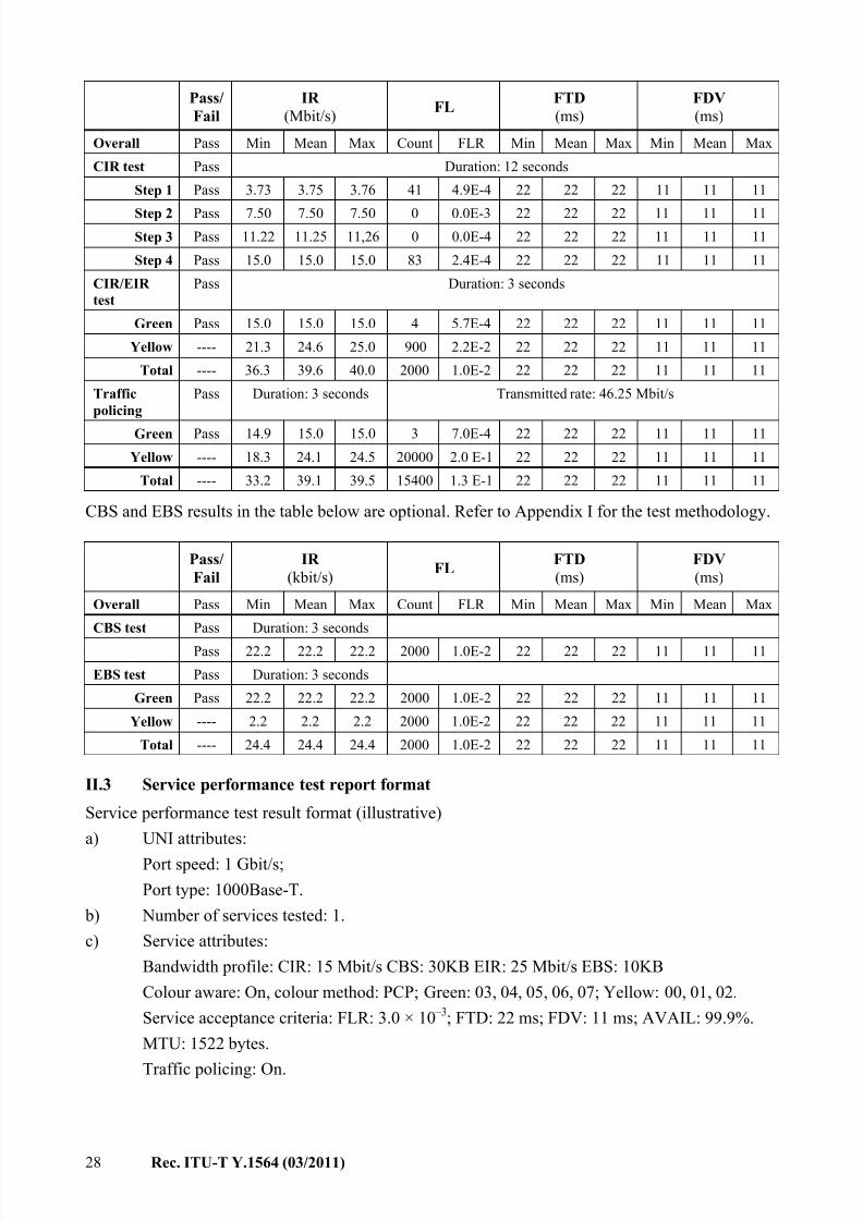
7/30/2019 T-REC-Y.1564-201103-I!!PDF-E
http://slidepdf.com/reader/full/t-rec-y1564-201103-ipdf-e 34/38
28 Rec. ITU-T Y.1564 (03/2011)
Pass/
Fail
IR
(Mbit/s) FL
FTD
(ms)
FDV
(ms)
Overall Pass Min Mean Max Count FLR Min Mean Max Min Mean Max
CIR test Pass Duration: 12 seconds
Step 1 Pass 3.73 3.75 3.76 41 4.9E-4 22 22 22 11 11 11
Step 2 Pass 7.50 7.50 7.50 0 0.0E-3 22 22 22 11 11 11
Step 3 Pass 11.22 11.25 11,26 0 0.0E-4 22 22 22 11 11 11
Step 4 Pass 15.0 15.0 15.0 83 2.4E-4 22 22 22 11 11 11
CIR/EIR
test
Pass Duration: 3 seconds
Green Pass 15.0 15.0 15.0 4 5.7E-4 22 22 22 11 11 11
Yellow ---- 21.3 24.6 25.0 900 2.2E-2 22 22 22 11 11 11
Total ---- 36.3 39.6 40.0 2000 1.0E-2 22 22 22 11 11 11
Traffic
policing
Pass Duration: 3 seconds Transmitted rate: 46.25 Mbit/s
Green Pass 14.9 15.0 15.0 3 7.0E-4 22 22 22 11 11 11
Yellow ---- 18.3 24.1 24.5 20000 2.0 E-1 22 22 22 11 11 11
Total ---- 33.2 39.1 39.5 15400 1.3 E-1 22 22 22 11 11 11
CBS and EBS results in the table below are optional. Refer to Appendix I for the test methodology.
Pass/
Fail
IR
(kbit/s) FL
FTD
(ms)
FDV
(ms)
Overall Pass Min Mean Max Count FLR Min Mean Max Min Mean Max
CBS test Pass Duration: 3 seconds
Pass 22.2 22.2 22.2 2000 1.0E-2 22 22 22 11 11 11
EBS test Pass Duration: 3 seconds
Green Pass 22.2 22.2 22.2 2000 1.0E-2 22 22 22 11 11 11
Yellow ---- 2.2 2.2 2.2 2000 1.0E-2 22 22 22 11 11 11
Total ---- 24.4 24.4 24.4 2000 1.0E-2 22 22 22 11 11 11
II.3 Service performance test report format
Service performance test result format (illustrative)
a) UNI attributes:
Port speed: 1 Gbit/s;
Port type: 1000Base-T.
b) Number of services tested: 1.
c) Service attributes:
Bandwidth profile: CIR: 15 Mbit/s CBS: 30KB EIR: 25 Mbit/s EBS: 10KB
Colour aware: On, colour method: PCP; Green: 03, 04, 05, 06, 07; Yellow: 00, 01, 02.
Service acceptance criteria: FLR: 3.0 × 10 –3; FTD: 22 ms; FDV: 11 ms; AVAIL: 99.9%.
MTU: 1522 bytes.
Traffic policing: On.
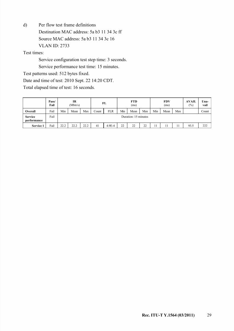
7/30/2019 T-REC-Y.1564-201103-I!!PDF-E
http://slidepdf.com/reader/full/t-rec-y1564-201103-ipdf-e 35/38
Rec. ITU-T Y.1564 (03/2011) 29
d) Per flow test frame definitions
Destination MAC address: 5a b3 11 34 3c ff
Source MAC address: 5a b3 11 34 3c 16
VLAN ID: 2733
Test times:
Service configuration test step time: 3 seconds.
Service performance test time: 15 minutes.
Test patterns used: 512 bytes fixed.
Date and time of test: 2010 Sept. 22 14:20 CDT.
Total elapsed time of test: 16 seconds.
Pass/
Fail
IR
(Mbit/s)FL
FTD
(ms) FDV
(ms) AVAIL
(%) Una-
vail
Overall Fail Min Mean Max Count FLR Min Mean Max Min Mean Max Count
Serviceperformance
Fail Duration: 15 minutes
Service 1 Fail 22.2 22.2 22.2 41 4.9E-4 22 22 22 11 11 11 93.5 222
7/30/2019 T-REC-Y.1564-201103-I!!PDF-E
http://slidepdf.com/reader/full/t-rec-y1564-201103-ipdf-e 36/38
30 Rec. ITU-T Y.1564 (03/2011)
Bibliography
[b-IEEE 802] IEEE 802-2001, IEEE Standard for Local and Metropolitan Area Networks:
Overview and Architecture.
[b-IEEE 802.1D] IEEE 802.1D-2004, IEEE standard for Local and Metropolitan Area
Networks – Media Access Control (MAC) Bridges.
[b-IEEE 802.1Q] IEEE 802.1Q-2010, IEEE standard for Local and Metropolitan Area
Networks – Media Access Control (MAC) Bridges and Virtual Bridged Local
Area Networks.
[b-IEEE 802.3] IEEE 802.3-2008, IEEE Standard for Information Technology –
Telecommunications and Information Exchange Between Systems – Local
and Metropolitan Area Networks – Specific requirements – Part 3: Carrier
Sense Multiple Access with Collision Detection (CSMA/CD) Access Method
and Physical Layer Specifications.
[b-IETF RFC 1242] RFC 1242 (1991), Benchmarking Terminology for Network Interconnection Devices.
[b-IETF RFC 2544] RFC 2544 (1999), Benchmarking Methodology for Network Interconnect
Devices.
[b-MEF 19] Technical Specification MEF 19 (2007), Abstract Test Suite for UNI Type 1.

7/30/2019 T-REC-Y.1564-201103-I!!PDF-E
http://slidepdf.com/reader/full/t-rec-y1564-201103-ipdf-e 37/38
7/30/2019 T-REC-Y.1564-201103-I!!PDF-E
http://slidepdf.com/reader/full/t-rec-y1564-201103-ipdf-e 38/38
SERIES OF ITU-T RECOMMENDATIONS
Series A Organization of the work of ITU-T
Series D General tariff principles
Series E Overall network operation, telephone service, service operation and human factors
Series F Non-telephone telecommunication services
Series G Transmission systems and media, digital systems and networks
Series H Audiovisual and multimedia systems
Series I Integrated services digital network
Series J Cable networks and transmission of television, sound programme and other multimedia signals
Series K Protection against interference
Series L Construction, installation and protection of cables and other elements of outside plant
Series M Telecommunication management, including TMN and network maintenance
Series N Maintenance: international sound programme and television transmission circuits
Series O Specifications of measuring equipment
Series P Terminals and subjective and objective assessment methods
Series Q Switching and signalling
Series R Telegraph transmission
Series S Telegraph services terminal equipment
Series T Terminals for telematic services
Series U Telegraph switching
Series V Data communication over the telephone network
Series X Data networks, open system communications and security
Series Y Global information infrastructure, Internet protocol aspects and next-generationnetworks
Series Z Languages and general software aspects for telecommunication systems